EP3339401A1 - Anlage und integriertes verfahren für hydrotreatment und hydrokonvertierung mit gemeinsamer fraktionierung - Google Patents
Anlage und integriertes verfahren für hydrotreatment und hydrokonvertierung mit gemeinsamer fraktionierung Download PDFInfo
- Publication number
- EP3339401A1 EP3339401A1 EP17206289.5A EP17206289A EP3339401A1 EP 3339401 A1 EP3339401 A1 EP 3339401A1 EP 17206289 A EP17206289 A EP 17206289A EP 3339401 A1 EP3339401 A1 EP 3339401A1
- Authority
- EP
- European Patent Office
- Prior art keywords
- pressure
- section
- effluent
- fraction
- unit
- Prior art date
- Legal status (The legal status is an assumption and is not a legal conclusion. Google has not performed a legal analysis and makes no representation as to the accuracy of the status listed.)
- Granted
Links
- 238000005194 fractionation Methods 0.000 title claims abstract description 142
- 238000000034 method Methods 0.000 title claims abstract description 75
- 238000006243 chemical reaction Methods 0.000 claims abstract description 124
- 229930195733 hydrocarbon Natural products 0.000 claims abstract description 35
- 150000002430 hydrocarbons Chemical class 0.000 claims abstract description 35
- 239000003350 kerosene Substances 0.000 claims abstract description 35
- 239000004215 Carbon black (E152) Substances 0.000 claims abstract description 24
- 108700042658 GAP-43 Proteins 0.000 claims abstract description 24
- 238000009434 installation Methods 0.000 claims abstract description 11
- 238000004519 manufacturing process Methods 0.000 claims abstract description 3
- 239000007788 liquid Substances 0.000 claims description 152
- 238000000926 separation method Methods 0.000 claims description 81
- 239000007789 gas Substances 0.000 claims description 74
- 238000004517 catalytic hydrocracking Methods 0.000 claims description 57
- 239000003921 oil Substances 0.000 claims description 40
- 235000019198 oils Nutrition 0.000 claims description 39
- 239000001257 hydrogen Substances 0.000 claims description 36
- 229910052739 hydrogen Inorganic materials 0.000 claims description 36
- 239000000203 mixture Substances 0.000 claims description 33
- 239000003054 catalyst Substances 0.000 claims description 31
- 239000002253 acid Substances 0.000 claims description 30
- UFHFLCQGNIYNRP-UHFFFAOYSA-N Hydrogen Chemical compound [H][H] UFHFLCQGNIYNRP-UHFFFAOYSA-N 0.000 claims description 26
- 238000004821 distillation Methods 0.000 claims description 17
- 150000001412 amines Chemical class 0.000 claims description 10
- 230000003197 catalytic effect Effects 0.000 claims description 10
- 230000005587 bubbling Effects 0.000 claims description 9
- 238000001816 cooling Methods 0.000 claims description 8
- 239000010457 zeolite Substances 0.000 claims description 7
- 239000003915 liquefied petroleum gas Substances 0.000 claims description 6
- 239000010687 lubricating oil Substances 0.000 claims description 6
- 229910021536 Zeolite Inorganic materials 0.000 claims description 5
- 239000006096 absorbing agent Substances 0.000 claims description 5
- 238000004939 coking Methods 0.000 claims description 5
- 239000002283 diesel fuel Substances 0.000 claims description 5
- HNPSIPDUKPIQMN-UHFFFAOYSA-N dioxosilane;oxo(oxoalumanyloxy)alumane Chemical compound O=[Si]=O.O=[Al]O[Al]=O HNPSIPDUKPIQMN-UHFFFAOYSA-N 0.000 claims description 5
- 238000005406 washing Methods 0.000 claims description 5
- 238000004523 catalytic cracking Methods 0.000 claims description 4
- 238000011084 recovery Methods 0.000 claims description 4
- 235000015112 vegetable and seed oil Nutrition 0.000 claims description 4
- 239000008158 vegetable oil Substances 0.000 claims description 4
- 241001465754 Metazoa Species 0.000 claims description 3
- 238000000605 extraction Methods 0.000 claims description 3
- 239000003502 gasoline Substances 0.000 claims description 3
- 239000002904 solvent Substances 0.000 claims description 3
- 238000006555 catalytic reaction Methods 0.000 claims description 2
- 150000004945 aromatic hydrocarbons Chemical class 0.000 claims 1
- 230000004907 flux Effects 0.000 description 76
- 239000000047 product Substances 0.000 description 53
- 241000861223 Issus Species 0.000 description 26
- IJGRMHOSHXDMSA-UHFFFAOYSA-N Atomic nitrogen Chemical compound N#N IJGRMHOSHXDMSA-UHFFFAOYSA-N 0.000 description 22
- 229910052751 metal Inorganic materials 0.000 description 18
- 239000002184 metal Substances 0.000 description 18
- 238000009835 boiling Methods 0.000 description 17
- 238000005520 cutting process Methods 0.000 description 17
- 229910052717 sulfur Inorganic materials 0.000 description 17
- NINIDFKCEFEMDL-UHFFFAOYSA-N Sulfur Chemical compound [S] NINIDFKCEFEMDL-UHFFFAOYSA-N 0.000 description 16
- 239000011593 sulfur Substances 0.000 description 15
- XLYOFNOQVPJJNP-UHFFFAOYSA-N water Chemical compound O XLYOFNOQVPJJNP-UHFFFAOYSA-N 0.000 description 13
- 238000002156 mixing Methods 0.000 description 12
- PXHVJJICTQNCMI-UHFFFAOYSA-N Nickel Chemical compound [Ni] PXHVJJICTQNCMI-UHFFFAOYSA-N 0.000 description 11
- 150000001875 compounds Chemical class 0.000 description 11
- 239000012530 fluid Substances 0.000 description 10
- 229910052757 nitrogen Inorganic materials 0.000 description 10
- 239000012071 phase Substances 0.000 description 10
- 241000196324 Embryophyta Species 0.000 description 9
- 150000002431 hydrogen Chemical class 0.000 description 9
- 230000006641 stabilisation Effects 0.000 description 9
- 239000000945 filler Substances 0.000 description 8
- 150000002739 metals Chemical class 0.000 description 8
- 238000007670 refining Methods 0.000 description 8
- 238000011144 upstream manufacturing Methods 0.000 description 8
- PNEYBMLMFCGWSK-UHFFFAOYSA-N aluminium oxide Inorganic materials [O-2].[O-2].[O-2].[Al+3].[Al+3] PNEYBMLMFCGWSK-UHFFFAOYSA-N 0.000 description 7
- 239000002737 fuel gas Substances 0.000 description 7
- 230000006835 compression Effects 0.000 description 6
- 238000007906 compression Methods 0.000 description 6
- JKWMSGQKBLHBQQ-UHFFFAOYSA-N diboron trioxide Chemical compound O=BOB=O JKWMSGQKBLHBQQ-UHFFFAOYSA-N 0.000 description 5
- 229910052500 inorganic mineral Inorganic materials 0.000 description 5
- 239000011707 mineral Substances 0.000 description 5
- 229910052750 molybdenum Inorganic materials 0.000 description 5
- 229910052759 nickel Inorganic materials 0.000 description 5
- 239000003208 petroleum Substances 0.000 description 5
- 238000011105 stabilization Methods 0.000 description 5
- CIWBSHSKHKDKBQ-JLAZNSOCSA-N Ascorbic acid Chemical compound OC[C@H](O)[C@H]1OC(=O)C(O)=C1O CIWBSHSKHKDKBQ-JLAZNSOCSA-N 0.000 description 4
- 208000036574 Behavioural and psychiatric symptoms of dementia Diseases 0.000 description 4
- ZOKXTWBITQBERF-UHFFFAOYSA-N Molybdenum Chemical compound [Mo] ZOKXTWBITQBERF-UHFFFAOYSA-N 0.000 description 4
- KDLHZDBZIXYQEI-UHFFFAOYSA-N Palladium Chemical compound [Pd] KDLHZDBZIXYQEI-UHFFFAOYSA-N 0.000 description 4
- VYPSYNLAJGMNEJ-UHFFFAOYSA-N Silicium dioxide Chemical compound O=[Si]=O VYPSYNLAJGMNEJ-UHFFFAOYSA-N 0.000 description 4
- 238000005336 cracking Methods 0.000 description 4
- 239000007924 injection Substances 0.000 description 4
- 238000002347 injection Methods 0.000 description 4
- 208000003173 lipoprotein glomerulopathy Diseases 0.000 description 4
- 239000007791 liquid phase Substances 0.000 description 4
- 239000011733 molybdenum Substances 0.000 description 4
- 230000000737 periodic effect Effects 0.000 description 4
- BASFCYQUMIYNBI-UHFFFAOYSA-N platinum Chemical compound [Pt] BASFCYQUMIYNBI-UHFFFAOYSA-N 0.000 description 4
- 238000011176 pooling Methods 0.000 description 4
- 238000003860 storage Methods 0.000 description 4
- 239000012808 vapor phase Substances 0.000 description 4
- ZOXJGFHDIHLPTG-UHFFFAOYSA-N Boron Chemical compound [B] ZOXJGFHDIHLPTG-UHFFFAOYSA-N 0.000 description 3
- OAICVXFJPJFONN-UHFFFAOYSA-N Phosphorus Chemical compound [P] OAICVXFJPJFONN-UHFFFAOYSA-N 0.000 description 3
- 240000008042 Zea mays Species 0.000 description 3
- 229910052796 boron Inorganic materials 0.000 description 3
- 238000010586 diagram Methods 0.000 description 3
- 238000005516 engineering process Methods 0.000 description 3
- 239000013067 intermediate product Substances 0.000 description 3
- 229910052698 phosphorus Inorganic materials 0.000 description 3
- 239000011574 phosphorus Substances 0.000 description 3
- CPLXHLVBOLITMK-UHFFFAOYSA-N Magnesium oxide Chemical compound [Mg]=O CPLXHLVBOLITMK-UHFFFAOYSA-N 0.000 description 2
- ATUOYWHBWRKTHZ-UHFFFAOYSA-N Propane Chemical compound CCC ATUOYWHBWRKTHZ-UHFFFAOYSA-N 0.000 description 2
- XUIMIQQOPSSXEZ-UHFFFAOYSA-N Silicon Chemical compound [Si] XUIMIQQOPSSXEZ-UHFFFAOYSA-N 0.000 description 2
- MCMNRKCIXSYSNV-UHFFFAOYSA-N Zirconium dioxide Chemical compound O=[Zr]=O MCMNRKCIXSYSNV-UHFFFAOYSA-N 0.000 description 2
- 230000002378 acidificating effect Effects 0.000 description 2
- 150000001336 alkenes Chemical class 0.000 description 2
- 230000001186 cumulative effect Effects 0.000 description 2
- 238000010908 decantation Methods 0.000 description 2
- 230000001419 dependent effect Effects 0.000 description 2
- 229940082150 encore Drugs 0.000 description 2
- 239000003925 fat Substances 0.000 description 2
- 238000010438 heat treatment Methods 0.000 description 2
- 239000011159 matrix material Substances 0.000 description 2
- 229910044991 metal oxide Inorganic materials 0.000 description 2
- 150000004706 metal oxides Chemical class 0.000 description 2
- VNWKTOKETHGBQD-UHFFFAOYSA-N methane Chemical compound C VNWKTOKETHGBQD-UHFFFAOYSA-N 0.000 description 2
- JKQOBWVOAYFWKG-UHFFFAOYSA-N molybdenum trioxide Chemical compound O=[Mo](=O)=O JKQOBWVOAYFWKG-UHFFFAOYSA-N 0.000 description 2
- 229910000510 noble metal Inorganic materials 0.000 description 2
- 229910052763 palladium Inorganic materials 0.000 description 2
- 229910052697 platinum Inorganic materials 0.000 description 2
- 238000004064 recycling Methods 0.000 description 2
- 229910052710 silicon Inorganic materials 0.000 description 2
- 239000010703 silicon Substances 0.000 description 2
- 239000000377 silicon dioxide Substances 0.000 description 2
- DLYUQMMRRRQYAE-UHFFFAOYSA-N tetraphosphorus decaoxide Chemical compound O1P(O2)(=O)OP3(=O)OP1(=O)OP2(=O)O3 DLYUQMMRRRQYAE-UHFFFAOYSA-N 0.000 description 2
- 229910052721 tungsten Inorganic materials 0.000 description 2
- 229910052720 vanadium Inorganic materials 0.000 description 2
- LEONUFNNVUYDNQ-UHFFFAOYSA-N vanadium atom Chemical compound [V] LEONUFNNVUYDNQ-UHFFFAOYSA-N 0.000 description 2
- OKTJSMMVPCPJKN-UHFFFAOYSA-N Carbon Chemical group [C] OKTJSMMVPCPJKN-UHFFFAOYSA-N 0.000 description 1
- CURLTUGMZLYLDI-UHFFFAOYSA-N Carbon dioxide Chemical compound O=C=O CURLTUGMZLYLDI-UHFFFAOYSA-N 0.000 description 1
- UGFAIRIUMAVXCW-UHFFFAOYSA-N Carbon monoxide Chemical compound [O+]#[C-] UGFAIRIUMAVXCW-UHFFFAOYSA-N 0.000 description 1
- OTMSDBZUPAUEDD-UHFFFAOYSA-N Ethane Chemical compound CC OTMSDBZUPAUEDD-UHFFFAOYSA-N 0.000 description 1
- 241001080024 Telles Species 0.000 description 1
- GWEVSGVZZGPLCZ-UHFFFAOYSA-N Titan oxide Chemical compound O=[Ti]=O GWEVSGVZZGPLCZ-UHFFFAOYSA-N 0.000 description 1
- 125000003118 aryl group Chemical group 0.000 description 1
- 230000015572 biosynthetic process Effects 0.000 description 1
- 238000009529 body temperature measurement Methods 0.000 description 1
- 229910052810 boron oxide Inorganic materials 0.000 description 1
- 239000001273 butane Substances 0.000 description 1
- 239000006227 byproduct Substances 0.000 description 1
- 229910052799 carbon Inorganic materials 0.000 description 1
- 229910002092 carbon dioxide Inorganic materials 0.000 description 1
- 229910002091 carbon monoxide Inorganic materials 0.000 description 1
- 229910017052 cobalt Inorganic materials 0.000 description 1
- 239000010941 cobalt Substances 0.000 description 1
- GUTLYIVDDKVIGB-UHFFFAOYSA-N cobalt atom Chemical compound [Co] GUTLYIVDDKVIGB-UHFFFAOYSA-N 0.000 description 1
- 239000000470 constituent Substances 0.000 description 1
- 238000010276 construction Methods 0.000 description 1
- 239000010779 crude oil Substances 0.000 description 1
- 238000004090 dissolution Methods 0.000 description 1
- 230000000694 effects Effects 0.000 description 1
- 230000008030 elimination Effects 0.000 description 1
- 238000003379 elimination reaction Methods 0.000 description 1
- 239000000446 fuel Substances 0.000 description 1
- 125000004435 hydrogen atom Chemical group [H]* 0.000 description 1
- 239000012535 impurity Substances 0.000 description 1
- 238000006317 isomerization reaction Methods 0.000 description 1
- 239000000395 magnesium oxide Substances 0.000 description 1
- 150000002736 metal compounds Chemical class 0.000 description 1
- IJDNQMDRQITEOD-UHFFFAOYSA-N n-butane Chemical compound CCCC IJDNQMDRQITEOD-UHFFFAOYSA-N 0.000 description 1
- OFBQJSOFQDEBGM-UHFFFAOYSA-N n-pentane Natural products CCCCC OFBQJSOFQDEBGM-UHFFFAOYSA-N 0.000 description 1
- 229910000480 nickel oxide Inorganic materials 0.000 description 1
- GNRSAWUEBMWBQH-UHFFFAOYSA-N oxonickel Chemical compound [Ni]=O GNRSAWUEBMWBQH-UHFFFAOYSA-N 0.000 description 1
- 239000001294 propane Substances 0.000 description 1
- 238000000746 purification Methods 0.000 description 1
- 238000005201 scrubbing Methods 0.000 description 1
- 238000010517 secondary reaction Methods 0.000 description 1
- -1 silica-aluminas Chemical compound 0.000 description 1
- 239000000243 solution Substances 0.000 description 1
- 238000001179 sorption measurement Methods 0.000 description 1
- 230000000087 stabilizing effect Effects 0.000 description 1
- OGIDPMRJRNCKJF-UHFFFAOYSA-N titanium oxide Inorganic materials [Ti]=O OGIDPMRJRNCKJF-UHFFFAOYSA-N 0.000 description 1
- WFKWXMTUELFFGS-UHFFFAOYSA-N tungsten Chemical compound [W] WFKWXMTUELFFGS-UHFFFAOYSA-N 0.000 description 1
- 239000010937 tungsten Substances 0.000 description 1
- 229910052727 yttrium Inorganic materials 0.000 description 1
Images


Classifications
-
- C—CHEMISTRY; METALLURGY
- C10—PETROLEUM, GAS OR COKE INDUSTRIES; TECHNICAL GASES CONTAINING CARBON MONOXIDE; FUELS; LUBRICANTS; PEAT
- C10G—CRACKING HYDROCARBON OILS; PRODUCTION OF LIQUID HYDROCARBON MIXTURES, e.g. BY DESTRUCTIVE HYDROGENATION, OLIGOMERISATION, POLYMERISATION; RECOVERY OF HYDROCARBON OILS FROM OIL-SHALE, OIL-SAND, OR GASES; REFINING MIXTURES MAINLY CONSISTING OF HYDROCARBONS; REFORMING OF NAPHTHA; MINERAL WAXES
- C10G67/00—Treatment of hydrocarbon oils by at least one hydrotreatment process and at least one process for refining in the absence of hydrogen only
- C10G67/02—Treatment of hydrocarbon oils by at least one hydrotreatment process and at least one process for refining in the absence of hydrogen only plural serial stages only
- C10G67/14—Treatment of hydrocarbon oils by at least one hydrotreatment process and at least one process for refining in the absence of hydrogen only plural serial stages only including at least two different refining steps in the absence of hydrogen
-
- C—CHEMISTRY; METALLURGY
- C10—PETROLEUM, GAS OR COKE INDUSTRIES; TECHNICAL GASES CONTAINING CARBON MONOXIDE; FUELS; LUBRICANTS; PEAT
- C10G—CRACKING HYDROCARBON OILS; PRODUCTION OF LIQUID HYDROCARBON MIXTURES, e.g. BY DESTRUCTIVE HYDROGENATION, OLIGOMERISATION, POLYMERISATION; RECOVERY OF HYDROCARBON OILS FROM OIL-SHALE, OIL-SAND, OR GASES; REFINING MIXTURES MAINLY CONSISTING OF HYDROCARBONS; REFORMING OF NAPHTHA; MINERAL WAXES
- C10G67/00—Treatment of hydrocarbon oils by at least one hydrotreatment process and at least one process for refining in the absence of hydrogen only
- C10G67/02—Treatment of hydrocarbon oils by at least one hydrotreatment process and at least one process for refining in the absence of hydrogen only plural serial stages only
-
- B—PERFORMING OPERATIONS; TRANSPORTING
- B01—PHYSICAL OR CHEMICAL PROCESSES OR APPARATUS IN GENERAL
- B01D—SEPARATION
- B01D3/00—Distillation or related exchange processes in which liquids are contacted with gaseous media, e.g. stripping
- B01D3/14—Fractional distillation or use of a fractionation or rectification column
- B01D3/143—Fractional distillation or use of a fractionation or rectification column by two or more of a fractionation, separation or rectification step
-
- C—CHEMISTRY; METALLURGY
- C10—PETROLEUM, GAS OR COKE INDUSTRIES; TECHNICAL GASES CONTAINING CARBON MONOXIDE; FUELS; LUBRICANTS; PEAT
- C10G—CRACKING HYDROCARBON OILS; PRODUCTION OF LIQUID HYDROCARBON MIXTURES, e.g. BY DESTRUCTIVE HYDROGENATION, OLIGOMERISATION, POLYMERISATION; RECOVERY OF HYDROCARBON OILS FROM OIL-SHALE, OIL-SAND, OR GASES; REFINING MIXTURES MAINLY CONSISTING OF HYDROCARBONS; REFORMING OF NAPHTHA; MINERAL WAXES
- C10G45/00—Refining of hydrocarbon oils using hydrogen or hydrogen-generating compounds
- C10G45/02—Refining of hydrocarbon oils using hydrogen or hydrogen-generating compounds to eliminate hetero atoms without changing the skeleton of the hydrocarbon involved and without cracking into lower boiling hydrocarbons; Hydrofinishing
-
- C—CHEMISTRY; METALLURGY
- C10—PETROLEUM, GAS OR COKE INDUSTRIES; TECHNICAL GASES CONTAINING CARBON MONOXIDE; FUELS; LUBRICANTS; PEAT
- C10G—CRACKING HYDROCARBON OILS; PRODUCTION OF LIQUID HYDROCARBON MIXTURES, e.g. BY DESTRUCTIVE HYDROGENATION, OLIGOMERISATION, POLYMERISATION; RECOVERY OF HYDROCARBON OILS FROM OIL-SHALE, OIL-SAND, OR GASES; REFINING MIXTURES MAINLY CONSISTING OF HYDROCARBONS; REFORMING OF NAPHTHA; MINERAL WAXES
- C10G47/00—Cracking of hydrocarbon oils, in the presence of hydrogen or hydrogen- generating compounds, to obtain lower boiling fractions
-
- C—CHEMISTRY; METALLURGY
- C10—PETROLEUM, GAS OR COKE INDUSTRIES; TECHNICAL GASES CONTAINING CARBON MONOXIDE; FUELS; LUBRICANTS; PEAT
- C10G—CRACKING HYDROCARBON OILS; PRODUCTION OF LIQUID HYDROCARBON MIXTURES, e.g. BY DESTRUCTIVE HYDROGENATION, OLIGOMERISATION, POLYMERISATION; RECOVERY OF HYDROCARBON OILS FROM OIL-SHALE, OIL-SAND, OR GASES; REFINING MIXTURES MAINLY CONSISTING OF HYDROCARBONS; REFORMING OF NAPHTHA; MINERAL WAXES
- C10G49/00—Treatment of hydrocarbon oils, in the presence of hydrogen or hydrogen-generating compounds, not provided for in a single one of groups C10G45/02, C10G45/32, C10G45/44, C10G45/58 or C10G47/00
-
- C—CHEMISTRY; METALLURGY
- C10—PETROLEUM, GAS OR COKE INDUSTRIES; TECHNICAL GASES CONTAINING CARBON MONOXIDE; FUELS; LUBRICANTS; PEAT
- C10G—CRACKING HYDROCARBON OILS; PRODUCTION OF LIQUID HYDROCARBON MIXTURES, e.g. BY DESTRUCTIVE HYDROGENATION, OLIGOMERISATION, POLYMERISATION; RECOVERY OF HYDROCARBON OILS FROM OIL-SHALE, OIL-SAND, OR GASES; REFINING MIXTURES MAINLY CONSISTING OF HYDROCARBONS; REFORMING OF NAPHTHA; MINERAL WAXES
- C10G65/00—Treatment of hydrocarbon oils by two or more hydrotreatment processes only
- C10G65/02—Treatment of hydrocarbon oils by two or more hydrotreatment processes only plural serial stages only
- C10G65/12—Treatment of hydrocarbon oils by two or more hydrotreatment processes only plural serial stages only including cracking steps and other hydrotreatment steps
-
- C—CHEMISTRY; METALLURGY
- C10—PETROLEUM, GAS OR COKE INDUSTRIES; TECHNICAL GASES CONTAINING CARBON MONOXIDE; FUELS; LUBRICANTS; PEAT
- C10G—CRACKING HYDROCARBON OILS; PRODUCTION OF LIQUID HYDROCARBON MIXTURES, e.g. BY DESTRUCTIVE HYDROGENATION, OLIGOMERISATION, POLYMERISATION; RECOVERY OF HYDROCARBON OILS FROM OIL-SHALE, OIL-SAND, OR GASES; REFINING MIXTURES MAINLY CONSISTING OF HYDROCARBONS; REFORMING OF NAPHTHA; MINERAL WAXES
- C10G65/00—Treatment of hydrocarbon oils by two or more hydrotreatment processes only
- C10G65/14—Treatment of hydrocarbon oils by two or more hydrotreatment processes only plural parallel stages only
-
- C—CHEMISTRY; METALLURGY
- C10—PETROLEUM, GAS OR COKE INDUSTRIES; TECHNICAL GASES CONTAINING CARBON MONOXIDE; FUELS; LUBRICANTS; PEAT
- C10G—CRACKING HYDROCARBON OILS; PRODUCTION OF LIQUID HYDROCARBON MIXTURES, e.g. BY DESTRUCTIVE HYDROGENATION, OLIGOMERISATION, POLYMERISATION; RECOVERY OF HYDROCARBON OILS FROM OIL-SHALE, OIL-SAND, OR GASES; REFINING MIXTURES MAINLY CONSISTING OF HYDROCARBONS; REFORMING OF NAPHTHA; MINERAL WAXES
- C10G7/00—Distillation of hydrocarbon oils
-
- C—CHEMISTRY; METALLURGY
- C10—PETROLEUM, GAS OR COKE INDUSTRIES; TECHNICAL GASES CONTAINING CARBON MONOXIDE; FUELS; LUBRICANTS; PEAT
- C10G—CRACKING HYDROCARBON OILS; PRODUCTION OF LIQUID HYDROCARBON MIXTURES, e.g. BY DESTRUCTIVE HYDROGENATION, OLIGOMERISATION, POLYMERISATION; RECOVERY OF HYDROCARBON OILS FROM OIL-SHALE, OIL-SAND, OR GASES; REFINING MIXTURES MAINLY CONSISTING OF HYDROCARBONS; REFORMING OF NAPHTHA; MINERAL WAXES
- C10G2300/00—Aspects relating to hydrocarbon processing covered by groups C10G1/00 - C10G99/00
- C10G2300/10—Feedstock materials
- C10G2300/1022—Fischer-Tropsch products
-
- C—CHEMISTRY; METALLURGY
- C10—PETROLEUM, GAS OR COKE INDUSTRIES; TECHNICAL GASES CONTAINING CARBON MONOXIDE; FUELS; LUBRICANTS; PEAT
- C10G—CRACKING HYDROCARBON OILS; PRODUCTION OF LIQUID HYDROCARBON MIXTURES, e.g. BY DESTRUCTIVE HYDROGENATION, OLIGOMERISATION, POLYMERISATION; RECOVERY OF HYDROCARBON OILS FROM OIL-SHALE, OIL-SAND, OR GASES; REFINING MIXTURES MAINLY CONSISTING OF HYDROCARBONS; REFORMING OF NAPHTHA; MINERAL WAXES
- C10G2300/00—Aspects relating to hydrocarbon processing covered by groups C10G1/00 - C10G99/00
- C10G2300/10—Feedstock materials
- C10G2300/1037—Hydrocarbon fractions
-
- C—CHEMISTRY; METALLURGY
- C10—PETROLEUM, GAS OR COKE INDUSTRIES; TECHNICAL GASES CONTAINING CARBON MONOXIDE; FUELS; LUBRICANTS; PEAT
- C10G—CRACKING HYDROCARBON OILS; PRODUCTION OF LIQUID HYDROCARBON MIXTURES, e.g. BY DESTRUCTIVE HYDROGENATION, OLIGOMERISATION, POLYMERISATION; RECOVERY OF HYDROCARBON OILS FROM OIL-SHALE, OIL-SAND, OR GASES; REFINING MIXTURES MAINLY CONSISTING OF HYDROCARBONS; REFORMING OF NAPHTHA; MINERAL WAXES
- C10G2300/00—Aspects relating to hydrocarbon processing covered by groups C10G1/00 - C10G99/00
- C10G2300/10—Feedstock materials
- C10G2300/1074—Vacuum distillates
-
- C—CHEMISTRY; METALLURGY
- C10—PETROLEUM, GAS OR COKE INDUSTRIES; TECHNICAL GASES CONTAINING CARBON MONOXIDE; FUELS; LUBRICANTS; PEAT
- C10G—CRACKING HYDROCARBON OILS; PRODUCTION OF LIQUID HYDROCARBON MIXTURES, e.g. BY DESTRUCTIVE HYDROGENATION, OLIGOMERISATION, POLYMERISATION; RECOVERY OF HYDROCARBON OILS FROM OIL-SHALE, OIL-SAND, OR GASES; REFINING MIXTURES MAINLY CONSISTING OF HYDROCARBONS; REFORMING OF NAPHTHA; MINERAL WAXES
- C10G2300/00—Aspects relating to hydrocarbon processing covered by groups C10G1/00 - C10G99/00
- C10G2300/10—Feedstock materials
- C10G2300/1077—Vacuum residues
-
- C—CHEMISTRY; METALLURGY
- C10—PETROLEUM, GAS OR COKE INDUSTRIES; TECHNICAL GASES CONTAINING CARBON MONOXIDE; FUELS; LUBRICANTS; PEAT
- C10G—CRACKING HYDROCARBON OILS; PRODUCTION OF LIQUID HYDROCARBON MIXTURES, e.g. BY DESTRUCTIVE HYDROGENATION, OLIGOMERISATION, POLYMERISATION; RECOVERY OF HYDROCARBON OILS FROM OIL-SHALE, OIL-SAND, OR GASES; REFINING MIXTURES MAINLY CONSISTING OF HYDROCARBONS; REFORMING OF NAPHTHA; MINERAL WAXES
- C10G2400/00—Products obtained by processes covered by groups C10G9/00 - C10G69/14
- C10G2400/02—Gasoline
-
- C—CHEMISTRY; METALLURGY
- C10—PETROLEUM, GAS OR COKE INDUSTRIES; TECHNICAL GASES CONTAINING CARBON MONOXIDE; FUELS; LUBRICANTS; PEAT
- C10G—CRACKING HYDROCARBON OILS; PRODUCTION OF LIQUID HYDROCARBON MIXTURES, e.g. BY DESTRUCTIVE HYDROGENATION, OLIGOMERISATION, POLYMERISATION; RECOVERY OF HYDROCARBON OILS FROM OIL-SHALE, OIL-SAND, OR GASES; REFINING MIXTURES MAINLY CONSISTING OF HYDROCARBONS; REFORMING OF NAPHTHA; MINERAL WAXES
- C10G2400/00—Products obtained by processes covered by groups C10G9/00 - C10G69/14
- C10G2400/04—Diesel oil
-
- C—CHEMISTRY; METALLURGY
- C10—PETROLEUM, GAS OR COKE INDUSTRIES; TECHNICAL GASES CONTAINING CARBON MONOXIDE; FUELS; LUBRICANTS; PEAT
- C10G—CRACKING HYDROCARBON OILS; PRODUCTION OF LIQUID HYDROCARBON MIXTURES, e.g. BY DESTRUCTIVE HYDROGENATION, OLIGOMERISATION, POLYMERISATION; RECOVERY OF HYDROCARBON OILS FROM OIL-SHALE, OIL-SAND, OR GASES; REFINING MIXTURES MAINLY CONSISTING OF HYDROCARBONS; REFORMING OF NAPHTHA; MINERAL WAXES
- C10G2400/00—Products obtained by processes covered by groups C10G9/00 - C10G69/14
- C10G2400/08—Jet fuel
Definitions
- the invention relates to the field of refining processes which comprise a reaction section producing H 2 S and / or light, an effluent separation section composed of at least one separation flask followed by a section splitting.
- the process according to the invention consists in fractionating the effluents of at least two units operating different processes in a common section without mixing them beforehand and feeding the flows produced in the separator flasks at different places in the column or columns ( s) fractionation.
- the common fractionation consists of a main fractionation column and optionally at least one light fraction separation column, called stripping column or stripper.
- the patent US 5,403,469 discloses a process in which a hydrotreatment unit and a hydrocracking unit are operated in parallel.
- the effluent from each of the reaction sections is collected in a common separator whose liquid fraction is sent to a single fractionation zone.
- all the effluents of the reaction section are thus mixed before being separated again in the fractionation section.
- the separator balloon being common to both units, they see the operating pressure of their linked reaction sections.
- This patent does not describe a method in which the feed of the common fractionation is done separately for the different streams from the separator flasks located downstream of the reaction sections of these two units and upstream of the fractionation or a process with a separating column treating the light fractions upstream of the main fractionation column.
- the patent application EP2710094 A4 describes a process in which two hydrocarbon feedstocks are treated in a hydrotreating unit ("hydroprocessing") and a hydrotreatment unit. A part of the effluent of the hydrotreating unit is mixed with the effluent of the hydrorefining unit. Then at least part of the mixture is sent to a zone of common splitting.
- This application does not describe a method in which the feed of the common fractionation is done separately for the different streams from the separator tanks located downstream of the reaction sections of these two units and upstream of the fractionation.
- Requirement FR 15 / 63.173 filed on December 23, 2015 by the Applicant, unpublished, describes a refining process that uses a reaction section producing H2S and / or light, a separation section composed of at least one separating flask, at least one fraction stripping column. light streams from the separator flasks and a fractionation column of the main products treating the bottom fraction of the stripping column and the heavy fractions from the separator flasks, each of the streams being supplied at different places in the fractionation columns.
- the energy efficiency of the process is maximized by separately feeding each of the streams produced by the different separator flasks from each separation section of each unit to optimal locations in the splitting section.
- the plant may include a C-7 acid gas treatment section comprising an amine absorber or a very low pressure wash column fed by at least a portion of the overhead fraction from main fractionator C -2 containing the residual acid gases.
- the plant may include a liquefied petroleum gas recovery section including one or more fractionation columns, fed by at least a portion of the top fraction from the main fractionating column C-2 containing the residual acid gases, or by the flow from the C7 acid gas treatment section.
- one or the other of the reaction sections comprises a hydroisomerization section including catalytic dewaxing, comprising at least one catalytic catalyst bed comprising a zeolite, a hydrogenating / dehydrogenating function. , and an acid function.
- the first unit is a hydrocracking unit and the second unit is a diesel hydrodesulfurization unit.
- the first unit is a hydroconversion unit of residue or distillate or bubbled deasphalted oil
- the second unit is a vacuum distillate hydrodesulfurization unit or diesel or kerosene unit.
- the first unit is a deasphalted deasphalted oil hydroconversion unit and the second unit is a vacuum distillate hydrodesulfurization unit.
- the invention also relates to an integrated process for hydrotreating and hydroconversion of gas oils, vacuum distillates, atmospheric or vacuum residues using the previously described plant, in which the C-1 separation column operates under the following conditions: total pressure between 0.4 MPa and 2.0 MPa, preferably between 0.6 and 2.0 MPa, very preferably between 0.7 and 1.8 MPa.
- the fractionation column C-2 advantageously operates under the following pressure conditions: total pressure of between 0.1 MPa and 0.4 MPa, preferably between 0.1 MPa and 0.3 MPa.
- the lateral stripping column (s) C-4, C-5 and C-6 advantageously operate under the following pressure conditions: total pressure of between 0.1 MPa and 0.4 MPa, preferably between 0.1 MPa and 0.3 MPa.
- the operating conditions of the hydrotreatment, hydroconversion and hydroisomerization catalytic reactions are advantageously: a temperature of the fixed bed reaction sections of between 200 and 460 ° C., an average temperature of the catalytic bed of the bubbling bed reaction sections of between 300 and 600 ° C. C, preferably between 350 ° C and 510 ° C, a total pressure of between 1.5 MPa and 35 MPa, preferably between 2 and 25 MPa, a global hourly space velocity of liquid charge for each catalytic step between 0 , 1 and 20 preferably between 0.15 and 15, an amount of hydrogen relative to the liquid charge of between 50 and 2500 Nm 3 / m 3 .
- the hydrocarbon feedstock is chosen from atmospheric distillate type feedstocks (naphtha, gasoline, kerosene and gas oils), vacuum distillate, for example gas oils, derived from from the direct distillation of crude or conversion units such as FCC, coking ( "coker” in English) or visbreaking, such as LCO (light cycle oil) light gas oil from a catalytic cracking unit, the feeds from aromatics extraction units, lubricating oil bases or from solvent dewaxing of lubricating oil bases, distillates from desulphurization or hydroconversion processes in fixed bed or bubbling bed of RAT (atmospheric residues) and / or RSV (vacuum residues) and / or deasphalted oils, deasphalted oils, effluents from a Fischer-Tropsch unit, vegetable oils, alone or as a mixture or animal fats .
- atmospheric distillate type feedstocks naphtha, gasoline, kerosene and gas oils
- vacuum distillate for example
- the hydrocarbon feedstock is chosen from gas oils, vacuum distillates, atmospheric or vacuum residues or Fischer-Tropsch unit effluents.
- hydrocracking or hydroconversion is meant a hydrogen cracking process, generally allowing, in crude oil refining, to convert a vacuum distillate to lighter products.
- hydrotreatment or hydrorefining means all the purification processes which make it possible to eliminate, by the action of hydrogen, the various impurities contained in the hydrocarbon fractions.
- Hydrotreating processes are used in refineries to purify hydrocarbon mixtures to make them easily recoverable products. They are usually mainly used for hydrodesulfurization, dearomatization, hydrodenitrogenation, etc. of fillers such as heavy petroleum or synthetic cuts, for example kerosenes, gas oils or distillates obtained from atmospheric distillation and under vacuum in order to produce kerosene, gasoil or vacuum distillate recoverable either in the storage unit receiving products of the same type ("pool” in English), or to a downstream unit such as catalytic cracking.
- small amounts of fuel gas fuel gas
- light cuts such as LPG and naphtha.
- the fractionation sections of a hydroconversion unit and a hydrodesulfurization unit can advantageously be pooled.
- a hydrocracking unit (a technology sold in particular under the name of Hyk TM ) and a diesel hydrodesulfurization unit (technology sold in particular under the name Prime-D TM).
- the hydroconversion process may also be a hydroconversion this technology is sold, for example, under the name of H-OIL® and the hydrodesulphurization process may be for example a vacuum distillate hydrodesulfurization unit or diesel or kerosene.
- the invention generally relates to refining processes which comprise a reaction section producing H 2 S and / or light compounds, a separation section of the effluent composed of at least one separation flask followed by a fractionation section.
- the light compounds to which reference is made are gaseous compounds at atmospheric pressure and ambient temperature, characterized by boiling points typically ranging up to about 20 ° C., for example hydrogen, methane, ethane, propane, butane or carbon monoxide or dioxide. This list is not exhaustive.
- the invention relates to the field of refining processes which comprise a reaction section producing H 2 S and / or light compounds, an effluent separation section composed of at least one separation flask followed by a section of splitting.
- the process according to the invention consists in fractionating the effluents of at least two units operating different processes in a common section without mixing them beforehand and feeding the flows produced in the separating flasks at different locations in the common fractionation.
- the common fractionation consists of a main fractionation column and possibly at least one stripping column of the light fractions, called the separation column.
- the plant according to the invention advantageously makes it possible to implement hydroconversion, hydrotreatment, hydrocracking or hydro-isomerization processes treating gas oils, kerosenes, vacuum distillates, atmospheric or vacuum residues. , deasphalted oils, vegetable oils or Fischer-Tropsch unit effluents.
- the invention may relate to units operating with fixed bed or bubbling bed reactors. This list of processes is not exhaustive.
- this unit may be a hydrocracking unit for gas oils, vacuum distillates, atmospheric or vacuum residues or Fischer-Tropsch unit effluent. This list is not exhaustive.
- At least one second unit of a different refining process, comprising a reaction section producing H 2 S and / or light ones, an effluent separation section composed of at least one separation flask followed by a common fractionation section with the first unit.
- the method used in the second unit does not require, when it is used in the usual manner by those skilled in the art, the main fractionation column of the products of the unit.
- this unit may be a section hydrotreating unit such as kerosene, diesel or distillates from the direct distillation of petroleum or other refining units. More generally, this unit may be a unit of any process comprising a reaction section producing H 2 S and / or light, followed by an effluent separation section composed of at least one separating flask. followed by a splitting section.
- the invention also relates to the method of implementing said installation.
- reaction sections R-1 and R-10 may comprise one or more reactors arranged in series or in parallel, for example two reactors arranged in series.
- Each reactor of a reaction section comprises at least one catalyst bed.
- the catalyst can be used in a fixed bed or in an expanded bed, or in a bubbling bed. In the case of a catalyst implemented in fixed bed, it is possible to have several catalyst beds in at least one reactor.
- Any catalyst known to those skilled in the art can be used in the process according to the invention, for example a catalyst comprising at least one element selected from the elements of Group VIII of the periodic table (Groups 8, 9 and 10 of the new periodic classification) and possibly at least one element selected from Group VIB elements of the Periodic Table (Group 6 of the new Periodic Table).
- a conventional hydroconversion catalyst comprising, on an amorphous support, at least one metal or metal compound having a hydro-dehydrogenating function.
- This catalyst may be a catalyst comprising Group VIII metals, for example nickel and / or cobalt, most often in combination with at least one Group VIB metal, for example molybdenum and / or tungsten.
- a catalyst comprising from 0.5 to 10% by weight of nickel (expressed as nickel oxide NiO) and from 1 to 30% by weight of molybdenum, preferably from 5 to 20% by weight of molybdenum (expressed as oxide of molybdenum MoO3) on an amorphous mineral support.
- the total content of Group VI and VIII metal oxides in the catalyst is generally between 5 and 40 percent by weight and preferably between 7 and 30 percent by weight.
- the weight ratio (expressed as metal oxides) between Group VI metal (metals) and Group VIII metal (metals) is, in general, from about 20 to about 1, and most often from about 10 to
- the support is, for example, selected from the group formed by alumina, silica, silica-aluminas, magnesia, clays and mixtures of at least two of these minerals. This support may also contain other compounds and, for example, oxides chosen from boron oxide, zirconia, titanium oxide and phosphoric anhydride. Most often, an alumina support is used, and preferably ⁇ or ⁇ alumina.
- the catalyst may also contain a promoter element such as phosphorus and / or boron. This element may have been introduced into the matrix or preferably deposited on the support. Silicon may also be deposited on the support, alone or with phosphorus and / or boron.
- the catalysts contain silicon deposited on a support such as alumina, optionally with phosphorus and / or boron deposited on the support, and also containing at least one metal of group VIII (Ni, Co ) and at least one Group VIB metal (Mo, W).
- the concentration of said element is usually less than about 20% by weight (on the oxide base) and most often less than about 10%.
- the concentration of boron trioxide (B2O3) is usually from about 0 to about 10% by weight.
- Another catalyst is a silica-alumina comprising at least one Group VIII metal and at least one Group VIB metal.
- Another type of usable catalyst is a catalyst containing at least one matrix, at least one zeolite Y and at least one dehydrogenating metal.
- the matrices, metals, additional elements previously described may also be included in the composition of this catalyst.
- Y advantageous zeolites are described in patent applications WO00 / 71641 , EP-911,077 as well as US 4,738,940 and 4738941 .
- Certain compounds having a basic character, such as basic nitrogen, are well known to significantly reduce the cracking activity of acidic catalysts such as silica-aluminas or zeolites.
- Another type of usable catalyst is a catalyst containing noble metals such as platinum or palladium, for example.
- the type of hydrotreating required, for example, to form a diesel fuel product may vary depending on the type of distillate feedstock. For certain types of feeds, the formation of a suitable diesel product may require only hydrotreating or hydrocracking of the feed to reduce the sulfur and nitrogen content in the diesel fuel produced. Other fillers will not have acceptable cold flow properties and will also require dewaxing to obtain the desired diesel.
- either of the reaction sections may also include a hydroisomerization section including catalytic dewaxing.
- the hydroisomerization consists of converting at least 10%, more precisely at least 50%, more particularly from 10 to 90% of the linear paraffins (n-paraffins) into branched paraffins (i-paraffins) in order to improve the cold properties of the charge: typically to obtain a cloud point of 0 ° C (32 ° F) or less, a pour point of 0 ° C (32 ° F) or less, and / or a filterability limit temperature (cold filter plugging point (CFPP) of 0 ° C (32 ° F) or less.
- CFPP filterability limit temperature
- the catalyst may include at least one Group VIII metal such as a noble metal (eg, platinum or palladium).
- the catalyst may also include a phosphated alumina silica or a silicated alumino zeolite.
- the operating conditions of these reaction hydrotreating or hydroconversion or hydroisomerization R-1 and R-10 sections are well known to those skilled in the art:
- the temperature of the fixed bed reaction sections is typically between 200 and 460 ° C. C.
- the average temperature of the catalyst bed (i.e., the arithmetic mean of the temperature measurements in the catalyst bed) of the bubbling bed reaction sections is typically between 300 and 600 ° C, preferably between 350 and 600 ° C. ° C and 510 ° C.
- the reaction section of the hydroconversion unit R-1 may be carried out in one step, or in one step with recycling of a portion of the unconverted product, or in several steps, each step having one or more reactors and processing part of the unconverted product.
- the separation section is generally common, at least in part, as is the fractionation section.
- the effluent from the reaction section R-1 or R-10 consists of a hydrocarbon fraction, generally in the mixed phase, comprising gases resulting from cracking, and in particular H 2 S and NH 3 resulting from the reactions of the reaction section, proportionally to the content of sulfur and nitrogen contained in the feed, possibly CO 2 and other gases, light cuts such as LPGs from secondary reactions, and at least naphtha, and possibly the hydrocarbon cuts; diesel, kerosene, unconverted residue, etc., depending on the nature of the charge and the type of reaction in R-1 or R-10.
- the separation column C-1 aims to eliminate the gases from cracking (generally called acid gases), and in particular the H 2 S and / or the light ones, resulting from the reactions of the section reaction.
- This column is preferably stripped by means of any stripping gas such as for example a gas containing hydrogen or steam.
- steam is used to carry out said stripping.
- the separation column C-1 may be reboiled using an oven or an exchanger whose hot flow may be a hot utility or a process flow internal or external to the unit .
- the total pressure is typically between 0.4 MPa and 2.0 MPa, generally between 0.6 and 2.0 MPa, preferably between 0.7 and 1.8 MPa.
- the pressure of this separation column is sufficiently high that the gases from this separation, previously purified from the H 2 S that they contain, can be reinjected into the fuel gas network of the site.
- the main fractional atmospheric column C-2 is also preferably fed by means of any stripping gas, preferably steam.
- the total pressure is generally between 0.1 MPa and 0.4 MPa, preferably between 0.1 MPa and 0.3 MPa.
- the cutting point of the atmospheric residue is typically set between 300 ° C and 400 ° C, preferably between 340 ° C and 380 ° C.
- the cuts withdrawn from the column are typically diesel, kerosene and naphtha.
- the lateral stripping column (s) C-4, C-5 and C-6 operate under the following pressure conditions: total pressure between 0.1 MPa and 0.4 MPa, preferably between 0.1 MPa and 0.3 MPa.
- the top fraction of the C-2 fractionation column contains the residual acid gases that are compressed in the K-3 compressor prior to export to the acid gas treatment (generally a amine wash or wash column). This fraction is then directed to a fuel gas network.
- At least part of the top fraction of the column C-2 containing the residual acid gases is sent to an amine absorber or a C-7 washing column operating at very low pressure, so that to eliminate at least a portion of the H 2 S.
- This portion of the overhead fraction can then be used in a minority way as fuel in furnaces R-1 or R-10 of the reaction sections.
- the residual gases can be directed, after washing with amines optionally, to a section for recovering liquefied petroleum gases (abbreviated as LPG in French or LPG in other countries) generally consisting of several columns. fractionation, for example deethanizer and debutanizer, this section being named "gas plant" according to the English terminology.
- LPG liquefied petroleum gases
- the hot high pressure separator tanks B-1 and B-10 are operated at a slightly lower pressure, for example a lower pressure of 0.1 MPa to 1.0 MPa than that of reactor R-1 and R-10, preferably at a pressure of between 1.4 and 35 MPa, preferably between 1.9 and 25 MPa.
- the temperature of the hot separator flask is generally between 200 ° C and 450 ° C, preferably between 250 ° C and 380 ° C and very preferably between 250 ° C and 360 ° C.
- the high-pressure cold separator tanks B-2 and B-20 whose charge is the gas stream from the hot separator tank B-1 and B-10 respectively, are operated at a pressure slightly lower than B-1 and B-1. Respectively, for example a lower pressure of 0.01 MPa lower to 1.0 MPa than that of B-1 and B-10, preferably at a pressure of 1.3 to 35 MPa, preferably between 1.9 and 25 MPa.
- the gaseous effluents from B-2 and B-20 respectively, called recycled hydrogen, are optionally washed in column C-3 and C-30 respectively, and then compressed in compressors K-1 and K-10 respectively.
- the temperature of the high pressure cold separator tanks B-2 and B-20 is generally as low as possible considering the cooling means available on the site. This is to maximize the purity of the recycled hydrogen, preferably between 20 and 100 ° C.
- the liquids coming from the high-pressure cold separator tanks B-2 and B-20 are expanded in a valve or a turbine and directed into the cold-pressure intermediate-pressure separator tanks B-4 and B-40 respectively.
- the total pressure of the latter is preferably that required to efficiently recover the hydrogen included in the separated gaseous fraction in these flasks. This recovery of hydrogen is preferably carried out in a pressure reversal adsorption unit.
- the pressure of the balloons B-4 and B-40 is generally between 1.0 MPa and 5.0 MPa, preferably between 1.5 MPa and 3.5 MPa.
- the liquid flow from the high-pressure hot separator tanks B-1 and B-10 is directed via a valve or a turbine into the medium-pressure hot-air separator tanks B-3 and B-30, respectively.
- the pressure of the latter is chosen so as to feed the cold medium pressure separator balloons B-4 and B-40 respectively with the separate gas stream in the high-pressure hot separator tanks B-3 and B-30, respectively.
- a part of the liquid coming from the B-4 and / or B-40 medium-pressure cold separator flasks can be re-injected into B-2 and / or B-20 respectively in order to promote the dissolution of the light hydrocarbons. in these and maximize the hydrogen purity of the recycle gas from the reaction section.
- the liquid flow from the hot medium pressure separator balloons B-3 and / or B-30 is expanded and directed to the low-pressure hot separator tanks B-5 and / or B-50 respectively.
- the pressure is chosen sufficiently high, so that the gaseous effluent from this separation can be directed either to the separation column C-1, or previously purified H 2 S that it contains, to the network of combustible gas from the site.
- the total pressure of these flasks is typically between about 0.2 MPa and about 2.5 MPa, typically between 0.3 and 2.0 MPa, preferably between 0.4 and 1.8 MPa.
- hydrocarbon feedstocks can be processed in the units concerned by the invention.
- Said fillers may be of petroleum or synthetic origin of mineral or biological source. The range extends from naphtha to vacuum residue through all intermediate cuts, or even a mixture of different cuts.
- fillers contain 5% or less of compounds whose boiling point is below 120 ° C (ie, 95% of the compounds present in the feed have a boiling point greater than 120 ° C).
- the boiling point T5 is generally about 120 ° C and in the case of diesel about 150 ° C. In the case of the atmospheric residue, the boiling point T5 is typically greater than 300 ° C, preferably between 340 ° C and 380 ° C.
- the boiling point T5 is typically between 450 ° C and 600 ° C, preferably between 500 ° C and 550 ° C.
- the light vacuum distillate (LVGO) is characterized by a distillation range of from 300 ° C to 430 ° C, preferably from 340 ° C to 400 ° C.
- the heavy vacuum oil distillate (HVGO according to the English terminology) is characterized by a distillation range of between 400 ° C. and 600 ° C., preferably between 440 ° C. and 550 ° C.
- the usable fillers are therefore in a wide range of boiling points.
- the hydrocarbon feedstocks may be of the atmospheric distillate type (naphtha, gasoline, kerosene and gas oils), vacuum distillate, for example gas oils, resulting from the direct distillation of the crude or from conversion units such as FCC, coking or visbreaking, such as LCO (light cycle oil) light gas oil from a catalytic cracking unit, but also can be charges from aromatic extraction units, lubricating oil bases or from solvent dewaxing bases lubricating oil, or distillates derived from fixed-bed or bubbling-bed desulphurization or hydroconversion processes of RAT (atmospheric residues) and / or RSV (vacuum residues) and / or deasphalted oils, or the charge may also be a deasphalted oil, effluents from a Fischer-Tropsch unit or any mixture of the aforementioned fillers.
- the hydrocarbon feed may also be vegetable oils or animal fats. The above list is not exhaustive.
- the charges of the hydroconversion units generally contain at least 10% volume, generally at least 20% volume, and often at least 80% volume of compounds boiling above 340 ° C.
- the nitrogen content of the feedstocks treated in the hydroconversion processes is usually greater than 500 ppm by weight, generally between 500 and 10,000 ppm by weight.
- the sulfur content of the feeds treated in the hydroconversion processes is usually between 0.01 and 6% by weight, generally between 0.2 and 5% by weight.
- the charge may optionally contain metals.
- the cumulative nickel and vanadium content of the feeds treated in the hydroconversion processes is preferably less than 10 ppm by weight, preferably less than 5 ppm by weight and even more preferably less than 2 ppm by weight.
- the asphaltene content is generally less than 3000 ppm by weight.
- the feedstocks of the hydrotreating units generally contain at least 10% by volume, usually at least 20% by volume, and often at least 80% by volume of compounds boiling above 150 ° C.
- the nitrogen content of the feedstocks treated in the hydrotreatment processes is usually greater than 100 ppm by weight, generally between 100 and 10,000 ppm by weight.
- the sulfur content of the feedstocks treated in the hydrotreatment processes is usually between 0.01 and 5% by weight.
- the charge may optionally contain metals.
- the cumulative nickel and vanadium content of the feeds treated in the hydrotreating processes is preferably less than 300 ppm by weight.
- the asphaltenes content is generally less than 15% by weight.
- the installation and the method according to the invention thus make it possible to obtain great flexibility in the cutting points for the intermediate products, with respect to the units taken independently.
- the implementation of the installation according to the invention also reduces the number of equipment during construction.
- the invention is advantageously implemented for units usually lacking a column allowing the main fractionation of the products of the unit.
- the flows from the separator flasks of these units can be treated in the main product fractionation column common with another unit, thus making it possible, without additional investments, to vary their cutting points.
- the process according to the invention makes it possible to obtain the same yield in hydrocarbon cuts while minimizing the investment costs.
- the properties of the finished products of each of the units must preferably be equivalent, that is to say they must have the same destination: typically either directly the recovery of the finished product in the same pool, or the treatment in the same unit of downstream refining, recycling at the same location.
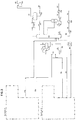
- the figure 1 illustrates a hydrocracking unit implemented according to the prior art.
- the filler 1 composed of petroleum hydrocarbons or synthetic hydrocarbons of mineral or biological source is mixed with hydrogen and then sent to a hydrocracking section.
- This section may comprise one or more reactors in fixed bed or bubbling bed.
- Each reactor may comprise one or more catalyst beds carrying out the hydrocracking of hydrocarbons in the lighter hydrocarbon feedstock.
- the hydrogen refill is fed via line 2 and compressor K-2 and then line 3, and mixed with the recycled hydrogen from compressor K-1 via line 16 before being mixed with charge 1.
- the mixture is admitted into a charge-effluent exchanger (E-1) via line 4.
- E-1 makes it possible to preheat the feedstock by means of the effluent from the hydrocracking reactor R-1.
- the charge is fed via line 5 into an oven F-1 making it possible to reach the temperature level necessary for the hydrocracking reaction, and then the hot charge is sent, via line 6, in at least one reactor R-1 comprising for example a hydrorefining or hydrocracking catalyst.
- the effluent from the reaction section at the outlet of the reactor R-1 is sent to the exchanger E-1, then via the line 11 to the hot separator tank at high pressure B-1.
- a gaseous fraction is separated in this flask and recovered via line 12.
- the hydrocracked liquid fraction is recovered in bottom via line 20.
- the gaseous fraction of the hot high pressure separator flask B-1 comprises unreacted hydrogen, the H 2 S possibly formed during the reaction, as well as light hydrocarbons resulting from reactions secondary to the reaction reaction. hydrocracking. After cooling in an exchanger E-2 and an aerocondenser A-1, this fraction is fed, via line 13, into a cold separator tank at high pressure B-2 allowing both a gas-liquid separation and optionally a decantation of the aqueous liquid phase, from the wash water optionally injected at high pressure upstream of E-2 and / or E-1.
- the liquid hydrocarbon phase is, after expansion in the valve or the liquid turbine V-1, directed into a cold medium pressure separator drum B-4 via line 21.
- the aqueous liquid phase is also directed, after expansion in a valve, to the B-4 cold medium pressure separator balloon via line 24.
- the liquid fraction of the hot high-pressure separator tank B-1 is, after expansion in the valve or the liquid turbine V-2, directed into a hot medium-pressure separator tank B-3 via line 20.
- a gaseous fraction is separated. in this flask and recovered via line 22.
- Said gaseous fraction comprises unreacted hydrogen, optionally H 2 S, and generally light hydrocarbons from the conversion of hydrocarbons from the feedstock in the section R-1 reaction.
- this fraction is fed via line 23 into the cold medium pressure separator drum B-4.
- the gaseous effluent from the B-4 flask constitutes a gaseous fraction rich in purged hydrogen via the line 25.
- the gaseous fraction from the high-pressure cold separator flask B-2 is sent via line 14 generally to an amine absorber or a C-3 scrubbing column making it possible to eliminate at least a portion of the H 2 S contained therein. .
- the gaseous fraction containing hydrogen is then recycled via lines 15 and 16 to the hydrocracking reactor, after compression using compressor K-1 and mixing with charge 1.
- the liquid fraction recovered at the bottom of the hot medium pressure flask B-3 is optionally expanded and directed via the lines 30 and 31 to the hot low-pressure separator flask B-5.
- the liquid effluent from the flask B-4 constitutes the light liquid fraction from the reaction effluent and feeds the stripper C-1 via the lines 32 and 33 after possibly preheating in the exchanger E-3.
- a gaseous fraction is optionally separated in the B-5 flask. This gaseous fraction can then feed the stripper C-1 via line 34 or in mixture with the liquid fraction from B-3 via line 33.
- Stripper C-1 is fed with stripping steam via line 35.
- a gaseous fraction (generally called acid gas) is recovered via line 36, and a naphtha with a final boiling point most often greater than 100 ° C via line 37.
- the liquid recovered in the bottom of stripper via line 39 is sent to the main fractionator C-2, without the need to heat it in a furnace or exchanger.
- the liquid fraction recovered at the hot medium pressure flask B-3 and / or optionally the liquid fraction obtained from B-5 constitutes the heavy fraction resulting from the reaction effluent and feeds, after preheating in the furnace F-2, the main fractionating column. C-2 through line 38, without being subjected to an acid gas separation operation in a stripping column or a reboiled separation column.
- the main fractionating column C-2 is operated typically at low pressure, for example 0.19 MPa at the top of the column.
- the heat required for separation is preferably provided by the temperature of the hot separator flasks B-3 and / or B-5.
- This column C-2 is also supplied with stripping steam via line 40.
- the overhead fraction recovered via line 41 contains the residual acid gases that are compressed in compressor K-3 prior to export to the acid gas treatment (usually an amine wash or wash column) before being directed to a reactor. fuel gas network.
- the product obtained line 50 consists of naphtha cuts having a final boiling point most often below 200 ° C.
- the intermediate fraction from the main fractionating column has its properties adjusted in the side column C-4 said side column is fed with a stripping fluid, for example steam.
- the intermediate fraction is extracted via the line 51 and then cooled, for example, by means of an exchanger E-4, and then recovered via the line 52. It is for example a diesel cut having a distillation temperature of 95.degree. % volume less than 360 ° C.
- the heavy fraction from the main fractionator via line 53 is also cooled using, for example, E-5 exchanger.
- the fraction thus obtained via line 55 is a vacuum gas oil having cutting points close to the initial charge.
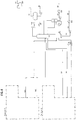
- the figure 2 illustrates a diesel hydrotreating unit implemented according to the prior art.
- the feedstock 101 composed of hydrocarbons of petroleum origin or of synthetic hydrocarbons of mineral or biological source is mixed with hydrogen and is then sent to a hydrotreatment section.
- This section may comprise one or more reactors, generally in fixed bed or bubbling bed.
- Each reactor may comprise one or more catalyst beds which hydrotreat the feedstock.
- the hydrogen booster is fed via the line 102 and the compressor K-20 and then the line 103, and mixed with the recycled hydrogen from the compressor K-10 by the line 116 before being mixed with the charge 101.
- the mixture is admitted into a charge-effluent exchanger (E-10) via line 104.
- E-10 makes it possible to preheat the feedstock by means of the effluent from the hydrotreating reactor R-10.
- the charge is fed via line 105 into an oven F-10 to reach the temperature level required for the hydrotreatment reaction, then the hot load is sent via line 106 in at least one R-10 reactor generally comprising at least one hydrodesulfurization catalyst.
- the effluent from the reaction section at the outlet of the reactor R-10 is sent to the exchanger E-10, then via the line 110 to the hot separator tank at high pressure B-10.
- a gaseous fraction is separated in this flask and recovered via line 112.
- the hydrotreated liquid fraction is recovered in bottom via line 120.
- Said gaseous fraction comprises unreacted hydrogen, the H2S optionally formed during the reaction, as well as light hydrocarbons from reactions secondary to the hydrotreatment reaction.
- this fraction is fed, via the line 113, into a cold separating high-pressure flask B-20 allowing both a gas-liquid separation and optionally a decantation of the aqueous liquid phase, from the wash water possibly injected at high pressure upstream of E-20 and / or E-10.
- the liquid hydrocarbon phase is, after expansion in the valve or the liquid turbine V-10, directed into a cold medium pressure separator tank B-40 via the line 121.
- the aqueous liquid phase is also directed, after expansion in a valve, to the cold medium pressure separator balloon B-40 via line 124.
- the liquid effluent from the flask B-10 is, after expansion in the valve or the liquid turbine V-20, directed into a hot medium pressure separator flask B-30 via the line 120.
- a gaseous fraction is separated in this flask. and recovered via line 122.
- Said gaseous fraction comprises unreacted hydrogen, optionally H 2 S, as well as generally light hydrocarbons.
- this fraction is fed, via the line 123, into the B-40 cold medium pressure separator flask.
- the gaseous effluent from the B-40 flask constitutes a gaseous fraction rich in hydrogen purged via the line 125.
- the gaseous fraction resulting from the high-pressure cold separator flask B-20 is sent via the line 14 generally to an amine absorber or a C-30 washing column making it possible to eliminate at least a portion of the H2S contained therein. .
- the gaseous fraction containing hydrogen is then recycled via the lines 115 and 116 to the reaction section, after compression using the compressor K-10 and mixing with the charge 101.
- the liquid effluent from the flask B-40 constitutes the light liquid fraction from the reaction effluent and feeds the stripper C-10 via the lines 132 and 133 after possibly preheating in the exchanger E-30.
- the liquid fraction recovered at the bottom of the hot medium pressure flask B-30 constitutes the heavy liquid fraction resulting from the reaction effluent. It feeds the stripper C-10 via lines 130 and 131 after mixing with the light liquid fraction from the balloon B-40
- Stripper C-10 is fed with stripping steam via line 135.
- a gaseous fraction (generally called acid gas) is recovered via line 136, and a naphtha having a final boiling point most often greater than 100 ° C and less than 200 ° C via line 137.
- the liquid recovered at the bottom of stripper via line 139 is sent to storage via line 142 after cooling in exchangers E-40, E-50 and in aerocondenser A-30.
- the figure 3 illustrates the plant according to the invention with a common fraction comprising a separation column C-1 (stripper) treating the light fractions and a main atmospheric fractionation column.
- C-1 stripper
- Section A of the hydrocracking unit is identical to section A described in figure 1 and section B of the diesel hydrotreating unit is identical to section B described in figure 2 .
- the liquid effluent from the cold medium pressure separator flask B-4 constitutes the light liquid fraction from the reaction effluent of the hydrocracking unit and feeds the stripper C-1 via lines 32 and 33 after possibly preheating in the reactor. exchanger E-3.
- a gaseous fraction is optionally separated from the heavy fraction from the reaction effluent of the hydrocracking unit in the hot low pressure flask B-5. This gaseous fraction can then feed the stripper C-1 via line 34 or in mixture with the liquid fraction from B-3 via line 33.
- the liquid effluent from the flask B-40 constitutes the light liquid fraction obtained from the reaction effluent of the diesel hydrotreating unit and feeds the stripper C-1 via the lines 132 and 133 after preheating in the exchanger E -30.
- Stripper C-1 is fed with stripping steam via line 35.
- a gaseous fraction (generally called acid gas) is recovered via line 36, and a naphtha with a final boiling point most often greater than 100 ° C via line 37.
- the liquid recovered in the bottom of stripper via line 39 is sent to the main fractionator C-2, without the need to heat it in a furnace or exchanger.
- the liquid fraction recovered at the hot medium pressure flask B-3 and / or optionally the liquid fraction obtained from B-5 constitutes the heavy fraction obtained from the reaction effluent of the hydrocracking unit and feeds, after preheating in the oven.
- the liquid fraction recovered at the bottom of the hot medium pressure flask B-30 constitutes the heavy liquid fraction obtained from the reaction effluent of the diesel hydrotreatment unit and directly feeds the main fractionating column C-2 via the line 131. without being subjected to an acid gas separation operation in a stripping column or a reboiled separation column.
- the feed is at a level distinct from the feed from the hydrocracking unit.
- the feed may be introduced either above or below the feed of the hydrocracking unit, but must be separated.
- the main fractionating column C-2 is operated typically at low pressure, for example 0.29 MPa at the top of the column.
- the heat required for separation is preferably provided by the temperature of the hot separator flasks B3 and / or B-5 and B-30 and optionally B-50.
- This column C-2 is also supplied with stripping steam via line 40.
- the overhead fraction recovered via line 41 contains the residual acid gases that are compressed in compressor K-3 prior to export to the acid gas treatment (usually an amine wash or wash column) before being directed to a reactor. fuel gas network.
- the product obtained line 50 consists of naphtha cuts having a final boiling point most often below 200 ° C.
- the intermediate fraction from the main fractionating column has its properties adjusted in the lateral stripping column C-4. Said column is fed with a stripping fluid.
- the intermediate fraction is extracted via line 51 and then cooled, for example, by means of an exchanger E-4. This is for example a diesel cut having a distillation temperature of 95% volume less than 360 ° C.
- the intermediate fraction consists of mixing the intermediate fraction from the hydrocracking unit and the intermediate fraction from the diesel hydrotreating unit.
- the heavy fraction from the main fractionator via line 53 is also cooled using, for example, E-5 exchanger.
- the fraction thus obtained via line 55 is a vacuum gas oil having cutting points close to the initial charge of the hydrocracking unit.
- the figure 4 illustrates the embodiment in which the common fractionation section does not contain a light fraction separation column (stripper or stabilization column) C-1.
- the common fractionation section comprises only one major fractional atmospheric column C-2 treating the effluents of two units independent of each other and a lateral stripping column C-4.
- the overhead fraction recovered via line 41 contains the residual acid gases that are compressed in compressor K-3 prior to export to the acid gas treatment (usually an amine wash or wash column) before being directed to a reactor. fuel gas network.
- the product obtained line 50 consists of naphtha cuts having a final boiling point most often below 200 ° C.
- the intermediate fraction from the main fractionating column has its properties adjusted in the lateral stripping column C-4. Said column is fed with a stripping fluid.
- the intermediate fraction is extracted via line 51 and then cooled, for example, by means of an exchanger E-4. It is, for example, a gas oil fraction having a distillation temperature at 95% volume less than 360 ° C. .
- the intermediate fraction consists of mixing the intermediate fraction from the hydrocracking unit and the intermediate fraction from the diesel hydrotreating unit.
- the heavy fraction from the main fractionator via line 53 is also cooled using, for example, E-5 exchanger.
- the fraction thus obtained via line 55 is a vacuum gas oil having cutting points close to the initial charge of the hydrocracking unit.
- An oven F-2 may optionally heat the charge (s) supplying the fractionation column C-2.
- This column is fed with a stripping fluid at the bottom of the column, usually water vapor, introduced via line 40.
- the role of the reaction section of the hydrocracking unit is to crack, as well as desulphurize, de-nitrogenize and saturate the olefins of the feedstock.
- the role of the reaction section of the diesel hydrotreatment unit is to desulphurize, denaze and saturate the olefins of the feedstock.
- the hydrocracking and hydrotreating units of diesel are first implemented independently of one another.
- the scheme of the hydrocracking unit is as follows: two-stage reaction section, then a common separation section at both stages, and then a fractionation section, consisting of a stripping column and an acidic fractionation column.
- the stripper C-1 is fed with the light phase resulting from the reaction section coming from the mixing of the liquid of the cold separator tank MP B-4 with the vapor phase of the hot separator tank LP B-5.
- the atmospheric fractionation column is fed by the bottom liquid of the stripper and by the heavy fraction from the reaction section constituted by the liquid of the hot separator tank LP B-5.
- the fractionation column consists of a main column and two adjacent columns (side stripper according to the English terminology) one C-4 for kerosene cutting (150 ° C-193 ° C) and the other C -5 for the diesel cut (193 ° C-371 ° C).
- the products of the fractionation column are an unconverted VGO (Unconverted Oil, UCO according to the English terminology), diesel and kerosene which are in mixture with the diesel pool and unstabilized naphtha which will be treated in a downstream section.
- VGO Unconverted Oil, UCO according to the English terminology
- the diagram of the diesel hydrotreatment unit is as follows: reaction section, then separation section, then fractionation section consisting of a stripping column which produces an unstabilized naphtha section and a diesel cut according to specifications, sent to the pool diesel.
- the stripper C-10 is fed with the mixture of the light fraction resulting from the reaction section constituted by the liquid of the cold separator drum MP B-40 and the heavy fraction resulting from the reaction section constituted by the liquid of the hot separator drum MP B-30 (cf. figure 2 ).
- the operating conditions of the reaction sections are as follows: ⁇ u> Table 2: ⁇ / u> Operational conditions of the reaction sections: Hydrotreatment of Diesel hydrocracking Overall hourly space velocity of liquid charge, h -1 1.0 1.7 (HDT 1 st step) 3.00 (HCK 1 st step) 2.0 (HCK 2 nd step)
- the operating conditions of the separation section of each of two units are as follows: ⁇ u> Table 3: ⁇ / u> Operating conditions of separator flasks Operating parameters Hydrocracking Separation Section Separation Section Diesel Hydrotreating Hot Separator High Pressure Temperature ° C 330 275 Pressure Mpa g 13.61 13.00 High Pressure Cold Separator Temperature ° C 55 55 Pressure Mpa g 13.6 12.70 Hot to Medium Pressure Separator Temperature ° C 337 283 Pressure Mpa g 2.63 2.58 Cold to Medium Pressure Separator Temperature ° C 55 77 Pressure Mpa g 2.55 2.55 Hot Separator at Low Pressure Temperature ° C 339 - Pressure Mpa g 0.96 -
- Example 2 (according to the invention) : The two units are then used, according to the invention, with a common fractionation section where the different liquid and gaseous streams coming from the separating flasks are fed to the appropriate places in the section. splitting.
- Table 5 shows that the finished products obtained in the process according to the invention with a common fractionation section are equivalent in quantity and quality to the finished products obtained.
- the diesel hydrotreating unit described in Example 1 with the feed described in Example 1 produces a Diesel + Kerosene cut which satisfies the properties of the diesel pool grade A to D.
- This unit can not with the same load produce a diesel that complies with the specifications for the diesel winter in the EN590: 2013 standard of July 2013, for temperate climates.
- the maximum filterability limit temperature Cold Filter Plugging Point in the English terminology
- the diesel hydrotreating unit and the hydrocracking unit are used as in Example 2 with a common fractionation section where the different liquid and gaseous flows from the balloons are separately fed to the suitable locations in the splitting section.
- the same diesel charge sent to the diesel hydrotreater allows produce various grades of diesel + kerosene including that compliant with grade E by adjusting the cutting point of the diesel in the common fractionation section.
- Example 4 illustrates the embodiment described on the Figure 4 with a common fractionation section comprising an atmospheric fractionation column C-2 without a C-1 separation column of the light fractions.
- the hydrocracking and hydrotreating units of diesel are first implemented independently of one another.
- the scheme of the hydrocracking unit is as follows: reaction section in two stages, then separation section, then fractionation section, consisting of a C-2 acid fractionation column without a C-1 light fraction separation column.
- the atmospheric fractionation column is fed by the heavy fraction resulting from the reaction section constituted by the liquid of the hot separator flask HP B-4, by the light fraction resulting from the reaction section coming from the liquid of the hot separator flask LP B-5 and the vapor phase of the hot separator flask LP B-5,
- the fractionation column C-2 consists of a main column and two adjacent columns (side stripper according to the English terminology), one C-4 for kerosene cutting (150 ° C-193 ° C) and the other C-5 for the diesel cut (193 ° C-371 ° C).
- the products of the fractionation column are an unconverted VGO (Unconverted Oil, UCO according to the English terminology), diesel and kerosene which are mixed with the diesel pool of the non-stabilized naphtha which will be treated in a downstream section and a fraction of acid gases.
- VGO Unconverted Oil, UCO according to the English terminology
- the scheme of the diesel hydrotreating unit is identical to the scheme of the diesel hydrotreating unit of Example 1.
- Table 10 shows that the finished products obtained according to the invention with a common fractionation section consisting of a main fractionation column and two lateral stripping columns, are equivalent in quantity and quality to the finished products obtained by mixing the products. of the two units implemented according to the prior art with each their fractionation section with regard to the diesel and kerosene mixture and for the unconverted VGO.
Landscapes
- Chemical & Material Sciences (AREA)
- Oil, Petroleum & Natural Gas (AREA)
- Chemical Kinetics & Catalysis (AREA)
- Engineering & Computer Science (AREA)
- General Chemical & Material Sciences (AREA)
- Organic Chemistry (AREA)
- Production Of Liquid Hydrocarbon Mixture For Refining Petroleum (AREA)
Applications Claiming Priority (1)
| Application Number | Priority Date | Filing Date | Title |
|---|---|---|---|
| FR1662929A FR3060404A1 (fr) | 2016-12-20 | 2016-12-20 | Installation et procede integre d'hydrotraitement et d'hydroconversion avec fractionnement commun |
Publications (2)
| Publication Number | Publication Date |
|---|---|
| EP3339401A1 true EP3339401A1 (de) | 2018-06-27 |
| EP3339401B1 EP3339401B1 (de) | 2019-10-30 |
Family
ID=58455200
Family Applications (1)
| Application Number | Title | Priority Date | Filing Date |
|---|---|---|---|
| EP17206289.5A Active EP3339401B1 (de) | 2016-12-20 | 2017-12-08 | Anlage und integriertes verfahren für hydrotreatment und hydrokonvertierung mit gemeinsamer fraktionierung |
Country Status (5)
| Country | Link |
|---|---|
| US (1) | US10760015B2 (de) |
| EP (1) | EP3339401B1 (de) |
| CN (1) | CN108203601B (de) |
| FR (1) | FR3060404A1 (de) |
| RU (1) | RU2750319C2 (de) |
Cited By (3)
| Publication number | Priority date | Publication date | Assignee | Title |
|---|---|---|---|---|
| FR3117127A1 (fr) | 2020-12-07 | 2022-06-10 | IFP Energies Nouvelles | Procédé d’hydrotraitement d’un flux liquide comprenant des hydrocarbures avec un flux gazeux comprenant de l’hydrogène |
| FR3117381A1 (fr) | 2020-12-15 | 2022-06-17 | IFP Energies Nouvelles | Procédé de production d’un catalyseur comprenant au moins un métal du groupe VIB, au moins un métal du groupe VIIIB et un support à base d’oxyde(s) |
| FR3126423A1 (fr) | 2021-08-26 | 2023-03-03 | IFP Energies Nouvelles | Procédé d’hydroconversion de charges hydrocarbonées |
Families Citing this family (6)
| Publication number | Priority date | Publication date | Assignee | Title |
|---|---|---|---|---|
| CN111974017B (zh) * | 2019-05-22 | 2022-08-30 | 中国石油天然气股份有限公司 | 分馏装置及分馏系统 |
| EP3744816A1 (de) | 2019-05-27 | 2020-12-02 | Indian Oil Corporation Limited | Verfahren zur herstellung von petrochemischen rohstoffen und benzin mit hoher oktanzahl aus mitteldestillaten |
| RU2759740C1 (ru) * | 2020-11-06 | 2021-11-17 | Публичное акционерное общество "Славнефть-Ярославнефтеоргсинтез", (ПАО "Славнефть-ЯНОС") | Способ получения летнего дизельного топлива |
| CA3230139A1 (en) * | 2021-09-16 | 2023-03-23 | Shell Internationale Research Maatschappij B.V. | Process for producing kerosene from renewable sources |
| CA3230142A1 (en) * | 2021-09-16 | 2023-03-23 | Shell Internationale Research Maatschappij B.V. | Process for producing kerosene and diesel from renewable sources |
| CA3230141A1 (en) * | 2021-09-16 | 2023-03-23 | Shell Internationale Research Maatschappij B.V. | Process for producing kerosene and diesel from renewable sources |
Citations (5)
| Publication number | Priority date | Publication date | Assignee | Title |
|---|---|---|---|---|
| US6072091A (en) * | 1995-12-27 | 2000-06-06 | Institut Francais Du Petrole | Process for selective hydrogenation of a hydrocarbon cut containing at least three carbon atoms |
| US20050103683A1 (en) * | 2003-11-14 | 2005-05-19 | Darush Farshid | Process for the upgrading of the products of Fischer-Tropsch processes |
| WO2012134838A2 (en) * | 2011-03-31 | 2012-10-04 | Uop Llc | Process and apparatus for producing diesel |
| US20130056394A1 (en) * | 2011-08-31 | 2013-03-07 | Instituto Mexicano Del Petroleo | Process of hydroconversion-distillation of heavy and/or extra-heavy crude oils |
| US20140158585A1 (en) * | 2011-06-09 | 2014-06-12 | Edmundo Steven Van Doesburg | Process for the preparation of a gas oil fraction |
Family Cites Families (8)
| Publication number | Priority date | Publication date | Assignee | Title |
|---|---|---|---|---|
| US5447621A (en) * | 1994-01-27 | 1995-09-05 | The M. W. Kellogg Company | Integrated process for upgrading middle distillate production |
| CN1098337C (zh) * | 2000-11-02 | 2003-01-08 | 中国石油天然气股份有限公司 | 一种采用多金属液体催化剂的常压重油悬浮床加氢新工艺 |
| US6787025B2 (en) * | 2001-12-17 | 2004-09-07 | Chevron U.S.A. Inc. | Process for the production of high quality middle distillates from mild hydrocrackers and vacuum gas oil hydrotreaters in combination with external feeds in the middle distillate boiling range |
| US7704377B2 (en) * | 2006-03-08 | 2010-04-27 | Institut Francais Du Petrole | Process and installation for conversion of heavy petroleum fractions in a boiling bed with integrated production of middle distillates with a very low sulfur content |
| CN100510021C (zh) * | 2007-01-22 | 2009-07-08 | 中国石油天然气华东勘察设计研究院 | 加氢反应流出物分离流程 |
| US20090159493A1 (en) * | 2007-12-21 | 2009-06-25 | Chevron U.S.A. Inc. | Targeted hydrogenation hydrocracking |
| US9005430B2 (en) * | 2009-12-10 | 2015-04-14 | IFP Energies Nouvelles | Process and apparatus for integration of a high-pressure hydroconversion process and a medium-pressure middle distillate hydrotreatment process, whereby the two processes are independent |
| US8747653B2 (en) * | 2011-03-31 | 2014-06-10 | Uop Llc | Process for hydroprocessing two streams |
-
2016
- 2016-12-20 FR FR1662929A patent/FR3060404A1/fr not_active Withdrawn
-
2017
- 2017-12-08 EP EP17206289.5A patent/EP3339401B1/de active Active
- 2017-12-19 RU RU2017144525A patent/RU2750319C2/ru active
- 2017-12-20 CN CN201711382611.7A patent/CN108203601B/zh active Active
- 2017-12-20 US US15/849,053 patent/US10760015B2/en active Active
Patent Citations (5)
| Publication number | Priority date | Publication date | Assignee | Title |
|---|---|---|---|---|
| US6072091A (en) * | 1995-12-27 | 2000-06-06 | Institut Francais Du Petrole | Process for selective hydrogenation of a hydrocarbon cut containing at least three carbon atoms |
| US20050103683A1 (en) * | 2003-11-14 | 2005-05-19 | Darush Farshid | Process for the upgrading of the products of Fischer-Tropsch processes |
| WO2012134838A2 (en) * | 2011-03-31 | 2012-10-04 | Uop Llc | Process and apparatus for producing diesel |
| US20140158585A1 (en) * | 2011-06-09 | 2014-06-12 | Edmundo Steven Van Doesburg | Process for the preparation of a gas oil fraction |
| US20130056394A1 (en) * | 2011-08-31 | 2013-03-07 | Instituto Mexicano Del Petroleo | Process of hydroconversion-distillation of heavy and/or extra-heavy crude oils |
Cited By (4)
| Publication number | Priority date | Publication date | Assignee | Title |
|---|---|---|---|---|
| FR3117127A1 (fr) | 2020-12-07 | 2022-06-10 | IFP Energies Nouvelles | Procédé d’hydrotraitement d’un flux liquide comprenant des hydrocarbures avec un flux gazeux comprenant de l’hydrogène |
| FR3117381A1 (fr) | 2020-12-15 | 2022-06-17 | IFP Energies Nouvelles | Procédé de production d’un catalyseur comprenant au moins un métal du groupe VIB, au moins un métal du groupe VIIIB et un support à base d’oxyde(s) |
| WO2022128491A1 (fr) | 2020-12-15 | 2022-06-23 | IFP Energies Nouvelles | Procédé de production d'un catalyseur comprenant au moins un métal du groupe vib, au moins un métal du groupe viiib et un support à base d'oxyde(s) |
| FR3126423A1 (fr) | 2021-08-26 | 2023-03-03 | IFP Energies Nouvelles | Procédé d’hydroconversion de charges hydrocarbonées |
Also Published As
| Publication number | Publication date |
|---|---|
| RU2750319C2 (ru) | 2021-06-25 |
| US10760015B2 (en) | 2020-09-01 |
| FR3060404A1 (fr) | 2018-06-22 |
| RU2017144525A3 (de) | 2020-12-15 |
| US20180171246A1 (en) | 2018-06-21 |
| CN108203601B (zh) | 2021-10-08 |
| EP3339401B1 (de) | 2019-10-30 |
| CN108203601A (zh) | 2018-06-26 |
| RU2017144525A (ru) | 2019-06-19 |
Similar Documents
| Publication | Publication Date | Title |
|---|---|---|
| EP3339401B1 (de) | Anlage und integriertes verfahren für hydrotreatment und hydrokonvertierung mit gemeinsamer fraktionierung | |
| EP3415588B1 (de) | Integriertes hydrocracking-verfahren in zwei stufen, und hydrotreating-verfahren | |
| KR101716986B1 (ko) | 전체 원유를 탈아스팔트 및 탈황시키기 위한 통합 공정 | |
| EP2788458B1 (de) | Verfahren zur hydrokonverion von erdöleinsätzen in festen betten zur erzeugung von brennstoffölen mit niedrigem schwefelgehalt | |
| US8110091B2 (en) | Process for the conversion of feedstocks resulting from renewable sources for producing gas oil fuel bases with a low sulphur content and with an improved cetane number | |
| JP6636034B2 (ja) | 炭化水素の水素化転化のためのプロセスおよび設備 | |
| EP3260520B1 (de) | Verbessertes verfahren der tiefen hydrokonversion anhand einer extraktion von aromastoffen und harzen mit valorisierung des hydrokonversions-extrakts und des raffinats bei den nachgeschalteten einheiten | |
| KR102328026B1 (ko) | 애노드 등급 코크스를 생산하기 위한 통합 공정 | |
| US20080093262A1 (en) | Process and installation for conversion of heavy petroleum fractions in a fixed bed with integrated production of middle distillates with a very low sulfur content | |
| FR3067037A1 (fr) | Procede de conversion comprenant un hydrotraitement en lit fixe, une separation d'un distillat sous vide, une etape d'hydrocraquage de distillat sous vide | |
| WO2008017742A1 (fr) | Procede et installation de traitement de petrole brut avec conversion de résidu asphalténique | |
| EP3184607B1 (de) | Hydrotreatment- oder hydrokonvertierungsverfahren mit stripper und niedrigdruck-trennbehälter auf dem fraktionierungsabschnitt | |
| WO2019134811A1 (fr) | Procede d'hydrocraquage deux etapes comprenant au moins une etape de separation haute pression a chaud | |
| CA2607252C (fr) | Procede et installation de conversion de fractions lourdes petrolieres en lit fixe avec production integree de distillats moyens a tres basse teneur en soufre | |
| FR3076297A1 (fr) | Procede integre d’hydrocraquage deux etapes pour maximiser la production de naphta | |
| FR3071845A1 (fr) | Procede integre de production de distillat moyen avec une boucle de recycle sur l'hydrotraitement | |
| FR3084372A1 (fr) | Procede de traitement d'une charge hydrocarbonee lourde comprenant un hydrotraitement en lit fixe, deux desasphaltages et un hydrocraquage en lit bouillonnant de l'asphalte | |
| FR3083243A1 (fr) | Procede integre d'hydrocraquage deux etapes et d'un procede d'hydrotraitement a circulation d'hydrogene inversee | |
| FR3084371A1 (fr) | Procede de traitement d'une charge hydrocarbonee lourde comprenant un hydrotraitement en lit fixe, un desasphaltage et un hydrocraquage en lit bouillonnant de l'asphalte | |
| FR2970478A1 (fr) | Procede d'hydroconversion en lit fixe d'un petrole brut, etete ou non, un fractionnement, puis un desasphaltage de la fraction lourde pour la production d'un brut synthetique preraffine | |
| EP3824049B1 (de) | Zweistufiges hydrocrackverfahren unter verwendung einer geteilten destillationskolonne | |
| WO2023241930A1 (fr) | Procédé d'hydrocraquage avec gestion du recyclage optimisée pour la production de naphta | |
| FR3097229A1 (fr) | Procede de production d’olefines comprenant un hydrotraitement, un desasphaltage, un hydrocraquage et un vapocraquage |
Legal Events
| Date | Code | Title | Description |
|---|---|---|---|
| PUAI | Public reference made under article 153(3) epc to a published international application that has entered the european phase |
Free format text: ORIGINAL CODE: 0009012 |
|
| STAA | Information on the status of an ep patent application or granted ep patent |
Free format text: STATUS: THE APPLICATION HAS BEEN PUBLISHED |
|
| AK | Designated contracting states |
Kind code of ref document: A1 Designated state(s): AL AT BE BG CH CY CZ DE DK EE ES FI FR GB GR HR HU IE IS IT LI LT LU LV MC MK MT NL NO PL PT RO RS SE SI SK SM TR |
|
| AX | Request for extension of the european patent |
Extension state: BA ME |
|
| STAA | Information on the status of an ep patent application or granted ep patent |
Free format text: STATUS: REQUEST FOR EXAMINATION WAS MADE |
|
| 17P | Request for examination filed |
Effective date: 20190102 |
|
| RBV | Designated contracting states (corrected) |
Designated state(s): AL AT BE BG CH CY CZ DE DK EE ES FI FR GB GR HR HU IE IS IT LI LT LU LV MC MK MT NL NO PL PT RO RS SE SI SK SM TR |
|
| REG | Reference to a national code |
Ref country code: DE Ref legal event code: R079 Ref document number: 602017008214 Country of ref document: DE Free format text: PREVIOUS MAIN CLASS: C10G0065140000 Ipc: B01D0003140000 |
|
| GRAP | Despatch of communication of intention to grant a patent |
Free format text: ORIGINAL CODE: EPIDOSNIGR1 |
|
| STAA | Information on the status of an ep patent application or granted ep patent |
Free format text: STATUS: GRANT OF PATENT IS INTENDED |
|
| RIC1 | Information provided on ipc code assigned before grant |
Ipc: C10G 7/00 20060101ALI20190429BHEP Ipc: C10G 47/00 20060101ALI20190429BHEP Ipc: C10G 67/14 20060101ALI20190429BHEP Ipc: C10G 45/02 20060101ALI20190429BHEP Ipc: B01D 3/14 20060101AFI20190429BHEP Ipc: C10G 65/14 20060101ALI20190429BHEP |
|
| INTG | Intention to grant announced |
Effective date: 20190524 |
|
| GRAS | Grant fee paid |
Free format text: ORIGINAL CODE: EPIDOSNIGR3 |
|
| GRAA | (expected) grant |
Free format text: ORIGINAL CODE: 0009210 |
|
| STAA | Information on the status of an ep patent application or granted ep patent |
Free format text: STATUS: THE PATENT HAS BEEN GRANTED |
|
| AK | Designated contracting states |
Kind code of ref document: B1 Designated state(s): AL AT BE BG CH CY CZ DE DK EE ES FI FR GB GR HR HU IE IS IT LI LT LU LV MC MK MT NL NO PL PT RO RS SE SI SK SM TR |
|
| REG | Reference to a national code |
Ref country code: GB Ref legal event code: FG4D Free format text: NOT ENGLISH |
|
| REG | Reference to a national code |
Ref country code: CH Ref legal event code: EP |
|
| REG | Reference to a national code |
Ref country code: AT Ref legal event code: REF Ref document number: 1195535 Country of ref document: AT Kind code of ref document: T Effective date: 20191115 |
|
| REG | Reference to a national code |
Ref country code: DE Ref legal event code: R096 Ref document number: 602017008214 Country of ref document: DE |
|
| REG | Reference to a national code |
Ref country code: IE Ref legal event code: FG4D Free format text: LANGUAGE OF EP DOCUMENT: FRENCH |
|
| REG | Reference to a national code |
Ref country code: NL Ref legal event code: FP |
|
| REG | Reference to a national code |
Ref country code: LT Ref legal event code: MG4D |
|
| PG25 | Lapsed in a contracting state [announced via postgrant information from national office to epo] |
Ref country code: PT Free format text: LAPSE BECAUSE OF FAILURE TO SUBMIT A TRANSLATION OF THE DESCRIPTION OR TO PAY THE FEE WITHIN THE PRESCRIBED TIME-LIMIT Effective date: 20200302 Ref country code: GR Free format text: LAPSE BECAUSE OF FAILURE TO SUBMIT A TRANSLATION OF THE DESCRIPTION OR TO PAY THE FEE WITHIN THE PRESCRIBED TIME-LIMIT Effective date: 20200131 Ref country code: LT Free format text: LAPSE BECAUSE OF FAILURE TO SUBMIT A TRANSLATION OF THE DESCRIPTION OR TO PAY THE FEE WITHIN THE PRESCRIBED TIME-LIMIT Effective date: 20191030 Ref country code: LV Free format text: LAPSE BECAUSE OF FAILURE TO SUBMIT A TRANSLATION OF THE DESCRIPTION OR TO PAY THE FEE WITHIN THE PRESCRIBED TIME-LIMIT Effective date: 20191030 Ref country code: SE Free format text: LAPSE BECAUSE OF FAILURE TO SUBMIT A TRANSLATION OF THE DESCRIPTION OR TO PAY THE FEE WITHIN THE PRESCRIBED TIME-LIMIT Effective date: 20191030 Ref country code: PL Free format text: LAPSE BECAUSE OF FAILURE TO SUBMIT A TRANSLATION OF THE DESCRIPTION OR TO PAY THE FEE WITHIN THE PRESCRIBED TIME-LIMIT Effective date: 20191030 Ref country code: NO Free format text: LAPSE BECAUSE OF FAILURE TO SUBMIT A TRANSLATION OF THE DESCRIPTION OR TO PAY THE FEE WITHIN THE PRESCRIBED TIME-LIMIT Effective date: 20200130 Ref country code: FI Free format text: LAPSE BECAUSE OF FAILURE TO SUBMIT A TRANSLATION OF THE DESCRIPTION OR TO PAY THE FEE WITHIN THE PRESCRIBED TIME-LIMIT Effective date: 20191030 Ref country code: BG Free format text: LAPSE BECAUSE OF FAILURE TO SUBMIT A TRANSLATION OF THE DESCRIPTION OR TO PAY THE FEE WITHIN THE PRESCRIBED TIME-LIMIT Effective date: 20200130 |
|
| PG25 | Lapsed in a contracting state [announced via postgrant information from national office to epo] |
Ref country code: IS Free format text: LAPSE BECAUSE OF FAILURE TO SUBMIT A TRANSLATION OF THE DESCRIPTION OR TO PAY THE FEE WITHIN THE PRESCRIBED TIME-LIMIT Effective date: 20200229 Ref country code: RS Free format text: LAPSE BECAUSE OF FAILURE TO SUBMIT A TRANSLATION OF THE DESCRIPTION OR TO PAY THE FEE WITHIN THE PRESCRIBED TIME-LIMIT Effective date: 20191030 Ref country code: HR Free format text: LAPSE BECAUSE OF FAILURE TO SUBMIT A TRANSLATION OF THE DESCRIPTION OR TO PAY THE FEE WITHIN THE PRESCRIBED TIME-LIMIT Effective date: 20191030 |
|
| PG25 | Lapsed in a contracting state [announced via postgrant information from national office to epo] |
Ref country code: AL Free format text: LAPSE BECAUSE OF FAILURE TO SUBMIT A TRANSLATION OF THE DESCRIPTION OR TO PAY THE FEE WITHIN THE PRESCRIBED TIME-LIMIT Effective date: 20191030 |
|
| PG25 | Lapsed in a contracting state [announced via postgrant information from national office to epo] |
Ref country code: EE Free format text: LAPSE BECAUSE OF FAILURE TO SUBMIT A TRANSLATION OF THE DESCRIPTION OR TO PAY THE FEE WITHIN THE PRESCRIBED TIME-LIMIT Effective date: 20191030 Ref country code: DK Free format text: LAPSE BECAUSE OF FAILURE TO SUBMIT A TRANSLATION OF THE DESCRIPTION OR TO PAY THE FEE WITHIN THE PRESCRIBED TIME-LIMIT Effective date: 20191030 Ref country code: CZ Free format text: LAPSE BECAUSE OF FAILURE TO SUBMIT A TRANSLATION OF THE DESCRIPTION OR TO PAY THE FEE WITHIN THE PRESCRIBED TIME-LIMIT Effective date: 20191030 Ref country code: ES Free format text: LAPSE BECAUSE OF FAILURE TO SUBMIT A TRANSLATION OF THE DESCRIPTION OR TO PAY THE FEE WITHIN THE PRESCRIBED TIME-LIMIT Effective date: 20191030 Ref country code: RO Free format text: LAPSE BECAUSE OF FAILURE TO SUBMIT A TRANSLATION OF THE DESCRIPTION OR TO PAY THE FEE WITHIN THE PRESCRIBED TIME-LIMIT Effective date: 20191030 |
|
| REG | Reference to a national code |
Ref country code: DE Ref legal event code: R097 Ref document number: 602017008214 Country of ref document: DE |
|
| REG | Reference to a national code |
Ref country code: AT Ref legal event code: MK05 Ref document number: 1195535 Country of ref document: AT Kind code of ref document: T Effective date: 20191030 |
|
| REG | Reference to a national code |
Ref country code: BE Ref legal event code: MM Effective date: 20191231 |
|
| PG25 | Lapsed in a contracting state [announced via postgrant information from national office to epo] |
Ref country code: MC Free format text: LAPSE BECAUSE OF FAILURE TO SUBMIT A TRANSLATION OF THE DESCRIPTION OR TO PAY THE FEE WITHIN THE PRESCRIBED TIME-LIMIT Effective date: 20191030 Ref country code: SK Free format text: LAPSE BECAUSE OF FAILURE TO SUBMIT A TRANSLATION OF THE DESCRIPTION OR TO PAY THE FEE WITHIN THE PRESCRIBED TIME-LIMIT Effective date: 20191030 Ref country code: IT Free format text: LAPSE BECAUSE OF FAILURE TO SUBMIT A TRANSLATION OF THE DESCRIPTION OR TO PAY THE FEE WITHIN THE PRESCRIBED TIME-LIMIT Effective date: 20191030 Ref country code: SM Free format text: LAPSE BECAUSE OF FAILURE TO SUBMIT A TRANSLATION OF THE DESCRIPTION OR TO PAY THE FEE WITHIN THE PRESCRIBED TIME-LIMIT Effective date: 20191030 |
|
| PLBE | No opposition filed within time limit |
Free format text: ORIGINAL CODE: 0009261 |
|
| STAA | Information on the status of an ep patent application or granted ep patent |
Free format text: STATUS: NO OPPOSITION FILED WITHIN TIME LIMIT |
|
| 26N | No opposition filed |
Effective date: 20200731 |
|
| PG25 | Lapsed in a contracting state [announced via postgrant information from national office to epo] |
Ref country code: LU Free format text: LAPSE BECAUSE OF NON-PAYMENT OF DUE FEES Effective date: 20191208 Ref country code: IE Free format text: LAPSE BECAUSE OF NON-PAYMENT OF DUE FEES Effective date: 20191208 |
|
| PG25 | Lapsed in a contracting state [announced via postgrant information from national office to epo] |
Ref country code: SI Free format text: LAPSE BECAUSE OF FAILURE TO SUBMIT A TRANSLATION OF THE DESCRIPTION OR TO PAY THE FEE WITHIN THE PRESCRIBED TIME-LIMIT Effective date: 20191030 Ref country code: BE Free format text: LAPSE BECAUSE OF NON-PAYMENT OF DUE FEES Effective date: 20191231 Ref country code: AT Free format text: LAPSE BECAUSE OF FAILURE TO SUBMIT A TRANSLATION OF THE DESCRIPTION OR TO PAY THE FEE WITHIN THE PRESCRIBED TIME-LIMIT Effective date: 20191030 |
|
| PG25 | Lapsed in a contracting state [announced via postgrant information from national office to epo] |
Ref country code: CY Free format text: LAPSE BECAUSE OF FAILURE TO SUBMIT A TRANSLATION OF THE DESCRIPTION OR TO PAY THE FEE WITHIN THE PRESCRIBED TIME-LIMIT Effective date: 20191030 |
|
| PG25 | Lapsed in a contracting state [announced via postgrant information from national office to epo] |
Ref country code: MT Free format text: LAPSE BECAUSE OF FAILURE TO SUBMIT A TRANSLATION OF THE DESCRIPTION OR TO PAY THE FEE WITHIN THE PRESCRIBED TIME-LIMIT Effective date: 20191030 Ref country code: HU Free format text: LAPSE BECAUSE OF FAILURE TO SUBMIT A TRANSLATION OF THE DESCRIPTION OR TO PAY THE FEE WITHIN THE PRESCRIBED TIME-LIMIT; INVALID AB INITIO Effective date: 20171208 |
|
| REG | Reference to a national code |
Ref country code: CH Ref legal event code: PL |
|
| PG25 | Lapsed in a contracting state [announced via postgrant information from national office to epo] |
Ref country code: CH Free format text: LAPSE BECAUSE OF NON-PAYMENT OF DUE FEES Effective date: 20201231 Ref country code: LI Free format text: LAPSE BECAUSE OF NON-PAYMENT OF DUE FEES Effective date: 20201231 |
|
| PG25 | Lapsed in a contracting state [announced via postgrant information from national office to epo] |
Ref country code: TR Free format text: LAPSE BECAUSE OF FAILURE TO SUBMIT A TRANSLATION OF THE DESCRIPTION OR TO PAY THE FEE WITHIN THE PRESCRIBED TIME-LIMIT Effective date: 20191030 |
|
| PG25 | Lapsed in a contracting state [announced via postgrant information from national office to epo] |
Ref country code: MK Free format text: LAPSE BECAUSE OF FAILURE TO SUBMIT A TRANSLATION OF THE DESCRIPTION OR TO PAY THE FEE WITHIN THE PRESCRIBED TIME-LIMIT Effective date: 20191030 |
|
| GBPC | Gb: european patent ceased through non-payment of renewal fee |
Effective date: 20211208 |
|
| PG25 | Lapsed in a contracting state [announced via postgrant information from national office to epo] |
Ref country code: GB Free format text: LAPSE BECAUSE OF NON-PAYMENT OF DUE FEES Effective date: 20211208 |
|
| PGFP | Annual fee paid to national office [announced via postgrant information from national office to epo] |
Ref country code: NL Payment date: 20231226 Year of fee payment: 7 Ref country code: FR Payment date: 20231226 Year of fee payment: 7 |
|
| PGFP | Annual fee paid to national office [announced via postgrant information from national office to epo] |
Ref country code: DE Payment date: 20231227 Year of fee payment: 7 |