EP3337685B1 - Verfahren und einrichtung zur haupt- und hilfsluftversorgung, insbesondere eines schienenfahrzeuges - Google Patents
Verfahren und einrichtung zur haupt- und hilfsluftversorgung, insbesondere eines schienenfahrzeuges Download PDFInfo
- Publication number
- EP3337685B1 EP3337685B1 EP16756975.5A EP16756975A EP3337685B1 EP 3337685 B1 EP3337685 B1 EP 3337685B1 EP 16756975 A EP16756975 A EP 16756975A EP 3337685 B1 EP3337685 B1 EP 3337685B1
- Authority
- EP
- European Patent Office
- Prior art keywords
- compressor
- vehicle
- air container
- switching
- main
- Prior art date
- Legal status (The legal status is an assumption and is not a legal conclusion. Google has not performed a legal analysis and makes no representation as to the accuracy of the status listed.)
- Active
Links
Images
Classifications
-
- B—PERFORMING OPERATIONS; TRANSPORTING
- B60—VEHICLES IN GENERAL
- B60T—VEHICLE BRAKE CONTROL SYSTEMS OR PARTS THEREOF; BRAKE CONTROL SYSTEMS OR PARTS THEREOF, IN GENERAL; ARRANGEMENT OF BRAKING ELEMENTS ON VEHICLES IN GENERAL; PORTABLE DEVICES FOR PREVENTING UNWANTED MOVEMENT OF VEHICLES; VEHICLE MODIFICATIONS TO FACILITATE COOLING OF BRAKES
- B60T17/00—Component parts, details, or accessories of power brake systems not covered by groups B60T8/00, B60T13/00 or B60T15/00, or presenting other characteristic features
- B60T17/02—Arrangements of pumps or compressors, or control devices therefor
-
- B—PERFORMING OPERATIONS; TRANSPORTING
- B60—VEHICLES IN GENERAL
- B60L—PROPULSION OF ELECTRICALLY-PROPELLED VEHICLES; SUPPLYING ELECTRIC POWER FOR AUXILIARY EQUIPMENT OF ELECTRICALLY-PROPELLED VEHICLES; ELECTRODYNAMIC BRAKE SYSTEMS FOR VEHICLES IN GENERAL; MAGNETIC SUSPENSION OR LEVITATION FOR VEHICLES; MONITORING OPERATING VARIABLES OF ELECTRICALLY-PROPELLED VEHICLES; ELECTRIC SAFETY DEVICES FOR ELECTRICALLY-PROPELLED VEHICLES
- B60L1/00—Supplying electric power to auxiliary equipment of vehicles
- B60L1/003—Supplying electric power to auxiliary equipment of vehicles to auxiliary motors, e.g. for pumps, compressors
-
- B—PERFORMING OPERATIONS; TRANSPORTING
- B60—VEHICLES IN GENERAL
- B60L—PROPULSION OF ELECTRICALLY-PROPELLED VEHICLES; SUPPLYING ELECTRIC POWER FOR AUXILIARY EQUIPMENT OF ELECTRICALLY-PROPELLED VEHICLES; ELECTRODYNAMIC BRAKE SYSTEMS FOR VEHICLES IN GENERAL; MAGNETIC SUSPENSION OR LEVITATION FOR VEHICLES; MONITORING OPERATING VARIABLES OF ELECTRICALLY-PROPELLED VEHICLES; ELECTRIC SAFETY DEVICES FOR ELECTRICALLY-PROPELLED VEHICLES
- B60L5/00—Current collectors for power supply lines of electrically-propelled vehicles
- B60L5/18—Current collectors for power supply lines of electrically-propelled vehicles using bow-type collectors in contact with trolley wire
- B60L5/22—Supporting means for the contact bow
- B60L5/24—Pantographs
-
- B—PERFORMING OPERATIONS; TRANSPORTING
- B60—VEHICLES IN GENERAL
- B60L—PROPULSION OF ELECTRICALLY-PROPELLED VEHICLES; SUPPLYING ELECTRIC POWER FOR AUXILIARY EQUIPMENT OF ELECTRICALLY-PROPELLED VEHICLES; ELECTRODYNAMIC BRAKE SYSTEMS FOR VEHICLES IN GENERAL; MAGNETIC SUSPENSION OR LEVITATION FOR VEHICLES; MONITORING OPERATING VARIABLES OF ELECTRICALLY-PROPELLED VEHICLES; ELECTRIC SAFETY DEVICES FOR ELECTRICALLY-PROPELLED VEHICLES
- B60L5/00—Current collectors for power supply lines of electrically-propelled vehicles
- B60L5/18—Current collectors for power supply lines of electrically-propelled vehicles using bow-type collectors in contact with trolley wire
- B60L5/22—Supporting means for the contact bow
- B60L5/28—Devices for lifting and resetting the collector
- B60L5/32—Devices for lifting and resetting the collector using fluid pressure
-
- B—PERFORMING OPERATIONS; TRANSPORTING
- B60—VEHICLES IN GENERAL
- B60R—VEHICLES, VEHICLE FITTINGS, OR VEHICLE PARTS, NOT OTHERWISE PROVIDED FOR
- B60R16/00—Electric or fluid circuits specially adapted for vehicles and not otherwise provided for; Arrangement of elements of electric or fluid circuits specially adapted for vehicles and not otherwise provided for
- B60R16/08—Electric or fluid circuits specially adapted for vehicles and not otherwise provided for; Arrangement of elements of electric or fluid circuits specially adapted for vehicles and not otherwise provided for fluid
-
- B—PERFORMING OPERATIONS; TRANSPORTING
- B60—VEHICLES IN GENERAL
- B60T—VEHICLE BRAKE CONTROL SYSTEMS OR PARTS THEREOF; BRAKE CONTROL SYSTEMS OR PARTS THEREOF, IN GENERAL; ARRANGEMENT OF BRAKING ELEMENTS ON VEHICLES IN GENERAL; PORTABLE DEVICES FOR PREVENTING UNWANTED MOVEMENT OF VEHICLES; VEHICLE MODIFICATIONS TO FACILITATE COOLING OF BRAKES
- B60T17/00—Component parts, details, or accessories of power brake systems not covered by groups B60T8/00, B60T13/00 or B60T15/00, or presenting other characteristic features
- B60T17/18—Safety devices; Monitoring
- B60T17/22—Devices for monitoring or checking brake systems; Signal devices
- B60T17/228—Devices for monitoring or checking brake systems; Signal devices for railway vehicles
-
- B—PERFORMING OPERATIONS; TRANSPORTING
- B60—VEHICLES IN GENERAL
- B60Y—INDEXING SCHEME RELATING TO ASPECTS CROSS-CUTTING VEHICLE TECHNOLOGY
- B60Y2200/00—Type of vehicle
- B60Y2200/30—Railway vehicles
- B60Y2200/33—Rail cars; Waggons
-
- B—PERFORMING OPERATIONS; TRANSPORTING
- B60—VEHICLES IN GENERAL
- B60Y—INDEXING SCHEME RELATING TO ASPECTS CROSS-CUTTING VEHICLE TECHNOLOGY
- B60Y2200/00—Type of vehicle
- B60Y2200/90—Vehicles comprising electric prime movers
- B60Y2200/91—Electric vehicles
- B60Y2200/912—Electric vehicles with power supply external to vehicle, e.g. trolley buses or trams
-
- B—PERFORMING OPERATIONS; TRANSPORTING
- B61—RAILWAYS
- B61C—LOCOMOTIVES; MOTOR RAILCARS
- B61C3/00—Electric locomotives or railcars
Definitions
- the invention relates to a method and a device for supplying main and auxiliary air to a vehicle with a compressor driven by an electric motor to generate compressed air for filling at least one main air tank for supplying pneumatic units of the vehicle, the vehicle having at least one first and second energy source is supplied with electrical energy, and wherein a pneumatic actuator for upgrading the vehicle and activating the first energy source is operated with the compressed air generated by the compressor, in that the electric motor of the compressor is fed via the second energy source in this phase.
- the field of application of the invention extends primarily to rail vehicle construction, namely to electrically operated rail vehicles which, for example, pick up the electrical energy required for operation from an overhead line via a pantograph.
- the vehicles of interest here also have a second energy source, for example in the form of a vehicle battery for storing electrical energy, which is provided for supplying electrical auxiliary units if the first energy source is not available.
- the compressed air generated by the compressor is primarily used to supply pneumatic units, such as a vehicle brake system. It is also conceivable to apply the present invention to non-rail vehicles such as trolley buses and the like.
- a so-called auxiliary air compressor is usually used for the auxiliary air supply in addition to a main compressor, which supplies the pneumatic energy for the actuator of the pantograph and provides the like.
- a separate auxiliary air compressor is supplied with electrical energy by the vehicle battery of the rail vehicle and has a relatively low delivery rate compared to the main compressor.
- the electrical energy of the vehicle battery is sufficient to drive the auxiliary air compressor with an electric motor, so that sufficient compressed air can be generated for the auxiliary air supply.
- the invention includes the technical teaching that the compressed air for upgrading the vehicle is supplied from a (main) compressor, preferably battery-operated via the second energy source, via a switching valve device to an auxiliary air tank assigned to the pneumatic actuator of the pantograph or main switch. Otherwise, that is, after the first energy source has been upgraded and activated, the compressed air generated by the compressor is fed to the main air tank via the switching valve device.
- the advantage of the solution according to the invention lies in the fact that the vehicle can be upgraded, i.e. ready for operation, by placing a pantograph on an electrical overhead line, for example, even with the main and auxiliary air tanks emptied in the initial state without a separate auxiliary compressor. Since the electric motor of the compressor is fed, for example via the vehicle battery as a second energy source, the compressor can initially fill the auxiliary air tank with compressed air with sufficient delivery capacity under valve control for the operation of the pneumatic actuator of the pantograph in order to extend the pantograph. If the first energy source is then connected via the pantograph, the compressor can be operated with normal delivery rate and the compressed air generated by this is made available to the main air tank and a main air tank line preferably assigned to it via the switching valve device.
- the switching valve device thus enables compressed air to be supplied as required, in particular in the operating phase of upgrading the vehicle.
- the switching valve device can be activated by the pressure in the auxiliary air container in such a way that if the pressure in the auxiliary air container falls below a minimum, it is refilled with compressed air. If the setpoint pressure in the auxiliary pressure tank is reached, the switching valve device can be switched over again so that the main air tank can again be filled with the compressed air generated by the compressor in a demand-controlled manner. This measure ensures that the auxiliary air tank is filled with compressed air with a higher priority than the main air tank.
- the switching pressure of the switching valve device is preferably below the nominal supply pressure of the main air tank. With a nominal supply pressure of 8.5 to 10 bar, the switching pressure can be 7.5 bar, for example.
- the auxiliary air container be filled with compressed air from the main air container if sufficient compressed air is stored therein.
- a valve element connected in parallel to the switching valve device can be provided in a simple manner, which valve element can also be part of the switching valve device.
- the valve element connected in parallel connects the main air tank with the auxiliary air tank, bypassing the switching valve device.
- the valve element can be designed as a spring-loaded check valve with a flow direction from the main air tank to the auxiliary air tank.
- the switching pressure can be adjusted via the spring strength of the check valve.
- the switching valve device according to the invention is preferably controlled electrically, the control unit in this case providing an electrical control signal.
- the switching valve device according to the invention can also be controlled mechanically, pneumatically or hydraulically instead.
- the switching valve device it is also possible, for example, for the switching valve device to be realized purely mechanically by means of an overflow valve and the pressure sensors by means of pressure switches.
- a control unit in particular an electronic control unit, can also be omitted.
- control unit is designed as an electronic control unit which, on the input side, is electrically connected to a pressure sensor on the main air tank and a pressure sensor on the auxiliary air tank.
- pressure sensors it is also possible to use binary switching pressure switches.
- the electronic control unit always has the current information on the prevailing pressure level in both tanks and can control the compressed air supply to the auxiliary and main air tanks depending on the priority, and the electronic control unit outputs a corresponding switching signal for the electrically controllable switching valve device.
- the electric motor of the compressor can also be controlled via the electronic control unit.
- the delivery rate of the compressor can preferably be adjusted by means of a converter connected upstream of the electric motor by varying the voltage and / or frequency. This can be done either variably or in fixed steps.
- the delivery rate of the compressor can also be varied by an electrical, pneumatic, hydraulic or mechanical actuation of a valve device, for example a venting device, on the compressor, for example between the high-pressure and low-pressure stage of a piston compressor that is multi-stage.
- the switching valve device can be designed as a 3/2-way valve which, in a first switching position, supplies the feed pressure generated by the compressor to the auxiliary air tank and, in a second switching position, supplies the feed pressure generated by the compressor to the main air tank.
- the switching valve device can also be designed as a 2/2-way valve which, in an open switching position, supplies the feed pressure generated by the compressor to the main air tank and, in a closed switching position, shuts off this connection, with a permanent compressed air connection from the compressor in addition to the auxiliary air reservoir.
- the application of compressed air to the auxiliary air tank has priority without the switching valve device having to be activated for this purpose.
- the compressor for supplying compressed air is usually followed by an air dryer unit which sufficiently dries the compressed air generated by the compressor from the ambient air before it is made available to the further compressed air system.
- the air dryer unit can be designed, for example, as an adsorption air dryer.
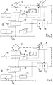
- a compressor 1 for generating compressed air for filling a main air tank 3 and a main air tank line 4 connected to it is provided as part of a main and auxiliary air supply of a rail vehicle (not shown in detail).
- the compressor 1 is driven by an electric motor 2.
- the electrical energy for driving the electric motor 2 is obtained primarily via a pantograph 5 via an overhead line connection.
- a vehicle battery 6 is used for a second electrical energy supply.
- the electrical energy supply by means of pantograph 5 and vehicle battery 6 is controlled via an electronic control unit 7, which also contains an integrated converter 8 for varying the voltage and frequencies for driving the electric motor 2.
- the electric motor 2 is designed here as a three-phase motor.
- a pneumatic actuator 9 assigned to the pantograph 5 is operated to retract and extend the pantograph 5 with the compressed air generated by the compressor 1.
- the electric motor 2 of the compressor 1 is initially supplied with electrical energy via the vehicle battery 6.
- the electrical energy that can be generated by the vehicle battery 6 is sufficient in this phase of upgrading the vehicle to operate the compressor 1 with a low delivery rate, which is sufficient to activate the pneumatic actuator 9 to extend the pantograph 5.
- Auxiliary air tank 11 is supplied, which stores the compressed air for operating the pneumatic actuator 9 of the pantograph 5.
- the switching valve device 10 supplies the compressed air generated by the compressor 1 to the main air tank 3 of the vehicle.
- the main air tank 3 of the vehicle is preferably filled with the primary electrical energy supply via the pantograph 5.
- auxiliary air tank 11 can also be filled from here.
- a valve element 12 connected in parallel to the switching valve device 10 is provided in the form of a non-return valve with a flow direction from the main air tank 3 to the auxiliary air tank 11.
- the switching valve device 10 is electrically controlled and the electronic control unit 7 specifies the electrical switching signal for this (dotted line).
- the electronic control unit 10 receives the pressure signal from a first pressure sensor 13 on the main air tank 3 and from a second pressure sensor 14 on the auxiliary air tank 11 (dotted lines). From this, the electronic control unit 10 determines the switching signal for the electrically controllable switching valve device 10 and for the compressor 1 in accordance with the logic explained above.
- the feed pressure generated by the compressor 1 is fed to the auxiliary air tank 11 in a first switching position - especially in the upgrade phase - and in a second switching position the feed pressure generated by the compressor 1 is fed to the main air tank 3 to ensure the main air supply to the vehicle.
- a switching valve device 10 ' is designed as a 2/2-way valve. In an open switching position, this leads to the feed pressure generated by the compressor 1 Main air tank 3 closed. In a closed switching position, the switching valve device 10 'blocks this connection. In addition, there is a permanent compressed air connection from the compressor 1 to the auxiliary air tank 11, which in this respect remains unaffected by the switching position of the switching valve device 10 '. In this way, a primary pressurization of the auxiliary air container 11 is achieved without actuating the valve.
- the switching valve device is not limited to the two preferred exemplary embodiments described above. Rather, modifications thereof are also conceivable, which are also covered by the scope of protection of the following claims.
- the switching valve device is also possible to design the switching valve device as a pneumatically, hydraulically or mechanically pilot-controlled valve and the control is carried out with the correspondingly suitable control medium.
- mechanical pressure monitors or the like can be used to monitor the pressure level in the main air tank 3 and the auxiliary air tank 11.
- the valve element connected in parallel with the switching valve device 10 or 10 ' can also be designed as an actively controlled valve or the like.
Landscapes
- Engineering & Computer Science (AREA)
- Mechanical Engineering (AREA)
- Transportation (AREA)
- Power Engineering (AREA)
- Physics & Mathematics (AREA)
- Fluid Mechanics (AREA)
- Fluid-Pressure Circuits (AREA)
- Compressors, Vaccum Pumps And Other Relevant Systems (AREA)
- Current-Collector Devices For Electrically Propelled Vehicles (AREA)
- Supply Devices, Intensifiers, Converters, And Telemotors (AREA)
- Vehicle Body Suspensions (AREA)
- Electric Propulsion And Braking For Vehicles (AREA)
Applications Claiming Priority (2)
| Application Number | Priority Date | Filing Date | Title |
|---|---|---|---|
| DE102015113940.5A DE102015113940A1 (de) | 2015-08-21 | 2015-08-21 | Verfahren und Einrichtung zur Haupt- und Hilfsluftversorgung, insbesondere eines Schienenfahrzeuges |
| PCT/EP2016/069199 WO2017032616A1 (de) | 2015-08-21 | 2016-08-12 | Verfahren und einrichtung zur haupt- und hilfsluftversorgung, insbesondere eines schienenfahrzeuges |
Publications (2)
| Publication Number | Publication Date |
|---|---|
| EP3337685A1 EP3337685A1 (de) | 2018-06-27 |
| EP3337685B1 true EP3337685B1 (de) | 2021-07-28 |
Family
ID=56800269
Family Applications (1)
| Application Number | Title | Priority Date | Filing Date |
|---|---|---|---|
| EP16756975.5A Active EP3337685B1 (de) | 2015-08-21 | 2016-08-12 | Verfahren und einrichtung zur haupt- und hilfsluftversorgung, insbesondere eines schienenfahrzeuges |
Country Status (8)
Cited By (1)
| Publication number | Priority date | Publication date | Assignee | Title |
|---|---|---|---|---|
| EP4013636B1 (de) | 2019-08-12 | 2024-09-25 | Schunk Transit Systems GmbH | Antriebsystem für einen stromabnehmer und verfahren zum anheben oder absenken |
Families Citing this family (4)
| Publication number | Priority date | Publication date | Assignee | Title |
|---|---|---|---|---|
| DE102017107276A1 (de) | 2017-04-05 | 2018-10-11 | Knorr-Bremse Systeme für Schienenfahrzeuge GmbH | Verfahren und Einrichtung für eine bedarfsgerechte Druckluftversorgung eines Fahrzeuges, insbesondere eines Schienenfahrzeuges |
| DE102017214111A1 (de) * | 2017-08-11 | 2019-02-14 | Knorr-Bremse Systeme für Schienenfahrzeuge GmbH | Elektropneumatisch geregelte Ansteuerung eines Stromabnehmers |
| JP7220561B2 (ja) * | 2018-12-26 | 2023-02-10 | ナブテスコ株式会社 | 鉄道車両用空気圧縮システム |
| KR102826428B1 (ko) * | 2023-10-10 | 2025-06-27 | 유진기공산업주식회사 | 반능동형 팬터그래프용 fail safe 압력제어밸브 |
Family Cites Families (17)
| Publication number | Priority date | Publication date | Assignee | Title |
|---|---|---|---|---|
| JPS59176301U (ja) | 1983-05-13 | 1984-11-26 | 株式会社日立製作所 | 車両用バツテリ−制御装置 |
| JPS6132701U (ja) | 1984-07-27 | 1986-02-27 | 株式会社日立製作所 | 空気圧式車両用パンタグラフ昇降制御装置 |
| JPS62126802A (ja) * | 1985-11-27 | 1987-06-09 | Hitachi Ltd | パンタグラフ昇降制御装置 |
| DE3613069A1 (de) * | 1986-04-18 | 1987-10-29 | Knorr Bremse Ag | Kompressoranlage, insbesondere fuer triebfahrzeuge im schienenfahrzeugbereich |
| JPH059101U (ja) | 1991-07-08 | 1993-02-05 | 株式会社日立製作所 | 鉄道車両用集電装置制御方式 |
| RU2100220C1 (ru) | 1996-12-25 | 1997-12-27 | Акционерное общество закрытого типа "Спецремонт" | Устройство управления пантографом |
| JP2004019625A (ja) | 2002-06-20 | 2004-01-22 | Matsushita Electric Ind Co Ltd | 風力利用エアーシステム |
| DE10336058B3 (de) * | 2003-08-01 | 2005-01-05 | Siemens Ag | Vorrichtung zum Bereitstellen eines Versorgungsdruckes |
| DE102006057065A1 (de) | 2006-11-29 | 2008-06-05 | Siemens Ag | Verfahren zum Bremsen eines Schienenfahrzeuges |
| DE102008056479A1 (de) * | 2008-11-05 | 2010-05-06 | Siemens Aktiengesellschaft | Druckluftsystem mit einem Druckbehälter und Verfahren zum Betreiben des Druckluftsystems |
| DE102010008636A1 (de) | 2010-02-18 | 2011-08-18 | Siemens Aktiengesellschaft, 80333 | Vorrichtung zum Bereitstellen eines Versorgungsdruckes |
| CN201863864U (zh) | 2010-11-25 | 2011-06-15 | 南车资阳机车有限公司 | 一种轨道车用空气制动系统 |
| CN102431458B (zh) | 2011-11-29 | 2013-12-04 | 南车株洲电力机车有限公司 | 一种受电弓控制装置及其控制方法 |
| KR101434311B1 (ko) | 2013-02-19 | 2014-08-27 | 현대로템 주식회사 | 철도차량의 공기압축기 기동 지연회로 및 그 철도차량 |
| RU130273U1 (ru) | 2013-02-28 | 2013-07-20 | Открытое Акционерное Общество "Российские Железные Дороги" | Электропневматическая тормозная система |
| DE102013109475B4 (de) | 2013-08-30 | 2018-12-06 | Knorr-Bremse Systeme für Schienenfahrzeuge GmbH | Verfahren und Einrichtung zur Hilfsluftversorgung eines Schienenfahrzeugs |
| DE102013217429A1 (de) * | 2013-09-02 | 2015-03-05 | Siemens Aktiengesellschaft | Druckluftsystem |
-
2015
- 2015-08-21 DE DE102015113940.5A patent/DE102015113940A1/de not_active Ceased
-
2016
- 2016-08-12 KR KR1020187006028A patent/KR102600362B1/ko active Active
- 2016-08-12 CN CN201680055409.0A patent/CN108025650B/zh active Active
- 2016-08-12 WO PCT/EP2016/069199 patent/WO2017032616A1/de active Application Filing
- 2016-08-12 EP EP16756975.5A patent/EP3337685B1/de active Active
- 2016-08-12 US US15/753,817 patent/US11130408B2/en active Active
- 2016-08-12 JP JP2018509780A patent/JP6820317B2/ja active Active
- 2016-08-12 RU RU2018109581A patent/RU2689677C1/ru active
Cited By (1)
| Publication number | Priority date | Publication date | Assignee | Title |
|---|---|---|---|---|
| EP4013636B1 (de) | 2019-08-12 | 2024-09-25 | Schunk Transit Systems GmbH | Antriebsystem für einen stromabnehmer und verfahren zum anheben oder absenken |
Also Published As
| Publication number | Publication date |
|---|---|
| RU2689677C1 (ru) | 2019-05-28 |
| KR20180041686A (ko) | 2018-04-24 |
| KR102600362B1 (ko) | 2023-11-08 |
| CN108025650A (zh) | 2018-05-11 |
| US11130408B2 (en) | 2021-09-28 |
| WO2017032616A1 (de) | 2017-03-02 |
| EP3337685A1 (de) | 2018-06-27 |
| DE102015113940A1 (de) | 2017-02-23 |
| CN108025650B (zh) | 2021-08-20 |
| JP2018532361A (ja) | 2018-11-01 |
| US20180265066A1 (en) | 2018-09-20 |
| JP6820317B2 (ja) | 2021-01-27 |
Similar Documents
| Publication | Publication Date | Title |
|---|---|---|
| EP3337685B1 (de) | Verfahren und einrichtung zur haupt- und hilfsluftversorgung, insbesondere eines schienenfahrzeuges | |
| DE102012010390B4 (de) | Niveauregelung für Fahrzeuge mit mindestens einer Luftfeder | |
| EP3038870B1 (de) | Verfahren und einrichtung zur hilfsluftversorgung eines schienenfahrzeuges | |
| EP2939892B1 (de) | Elektrische Feststellbremse für ein Fahrzeug | |
| EP3331738B1 (de) | Vorrichtung und verfahren zur druckluftversorgung | |
| DE102007030441A1 (de) | Bremssystem für ein Kraftahrzeug und Verfahren zum Betreiben eines Bremssystems eines Kraftfahrzeugs | |
| DE102013107503A1 (de) | Feststellbremseinrichtung für ein Zugfahrzeug einer Zugfahrzeug-Anhängerkombination mit nachrüstbarer Streckbremsventileinrichtung | |
| EP3292031B2 (de) | Verfahren zum betrieb eines parkbremssystems für nutzfahrzeuge, sowie vorrichtung hierzu | |
| DE102017107276A1 (de) | Verfahren und Einrichtung für eine bedarfsgerechte Druckluftversorgung eines Fahrzeuges, insbesondere eines Schienenfahrzeuges | |
| EP2939891A2 (de) | Elektrische Feststellbremse | |
| EP3758990A1 (de) | Notlöseeinrichtung für eine federspeicherbremse eines schienenfahrzeugs | |
| EP3347227A1 (de) | Verfahren und einrichtung zur ansteuerung von energiequellen für die haupt- und hilfsluftversorgung, insbesondere eines schienenfahrzeuges | |
| DE102004027256A1 (de) | Bremssystem eines Kraftfahrzeuges | |
| DE102013223363A1 (de) | Verfahren zur Entlüftung einer hydraulischen Fahrzeug-Bremsanlage sowie Bremsanlagen-Steuereinrichtung | |
| EP3996962B1 (de) | Parkbremseinrichtung | |
| DE102015121950A1 (de) | Verfahren zum Steuern einer elektro-pneumatischen Parkbremseinrichtung eines Fahrzeugs während der Fahrt als Hilfsbremse | |
| WO2009056305A1 (de) | Ventilanordnung zur steuerung einer bremsanlage einer feststellbremsanlage eines schienenfahrzeugs | |
| EP3925840B1 (de) | Kraftfahrzeug mit druckluftsystem | |
| DE102014217428A1 (de) | Hydraulikaggregat für ein Bremssystem eines Fahrzeugs, Bremssystem für ein Fahrzeug und Verfahren zum Betreiben eines Bremssystems eines Fahrzeugs | |
| EP2855218B1 (de) | Fülleinrichtung für eine schienenfahrzeugnotbremsleitung | |
| EP1440211A1 (de) | Arbeitsmaschine und verfahren zum betreiben einer arbeitsmaschine | |
| WO2013174569A2 (de) | Verfahren zum öffnen oder schliessen einer elektrisch bzw. elektronisch ansteuerbaren schalteinrichtung eines fahrzeugs | |
| DE102022117696B3 (de) | Anordnung und Verfahren zum Hilfslösen einer Bremse eines Schienenfahrzeugs sowie Schienenfahrzeug | |
| EP1300308B1 (de) | Verfahren zum Betrieb einer druckluftbetriebenen Bremsanlage eines Fahrzeugverbandes sowie Zugfahrzeug mit druckluftbetriebener Bremsanlage | |
| EP3921212B1 (de) | Bremssteuergeräteanordnung und verfahren zum steuern einer bremssteuergeräteanordnung einer bremse für schienenfahrzeuge |
Legal Events
| Date | Code | Title | Description |
|---|---|---|---|
| STAA | Information on the status of an ep patent application or granted ep patent |
Free format text: STATUS: THE INTERNATIONAL PUBLICATION HAS BEEN MADE |
|
| PUAI | Public reference made under article 153(3) epc to a published international application that has entered the european phase |
Free format text: ORIGINAL CODE: 0009012 |
|
| STAA | Information on the status of an ep patent application or granted ep patent |
Free format text: STATUS: REQUEST FOR EXAMINATION WAS MADE |
|
| 17P | Request for examination filed |
Effective date: 20180321 |
|
| AK | Designated contracting states |
Kind code of ref document: A1 Designated state(s): AL AT BE BG CH CY CZ DE DK EE ES FI FR GB GR HR HU IE IS IT LI LT LU LV MC MK MT NL NO PL PT RO RS SE SI SK SM TR |
|
| AX | Request for extension of the european patent |
Extension state: BA ME |
|
| DAV | Request for validation of the european patent (deleted) | ||
| DAX | Request for extension of the european patent (deleted) | ||
| GRAP | Despatch of communication of intention to grant a patent |
Free format text: ORIGINAL CODE: EPIDOSNIGR1 |
|
| STAA | Information on the status of an ep patent application or granted ep patent |
Free format text: STATUS: GRANT OF PATENT IS INTENDED |
|
| INTG | Intention to grant announced |
Effective date: 20210217 |
|
| GRAS | Grant fee paid |
Free format text: ORIGINAL CODE: EPIDOSNIGR3 |
|
| GRAA | (expected) grant |
Free format text: ORIGINAL CODE: 0009210 |
|
| STAA | Information on the status of an ep patent application or granted ep patent |
Free format text: STATUS: THE PATENT HAS BEEN GRANTED |
|
| AK | Designated contracting states |
Kind code of ref document: B1 Designated state(s): AL AT BE BG CH CY CZ DE DK EE ES FI FR GB GR HR HU IE IS IT LI LT LU LV MC MK MT NL NO PL PT RO RS SE SI SK SM TR |
|
| REG | Reference to a national code |
Ref country code: GB Ref legal event code: FG4D Free format text: NOT ENGLISH |
|
| REG | Reference to a national code |
Ref country code: CH Ref legal event code: EP |
|
| REG | Reference to a national code |
Ref country code: DE Ref legal event code: R096 Ref document number: 502016013498 Country of ref document: DE |
|
| REG | Reference to a national code |
Ref country code: AT Ref legal event code: REF Ref document number: 1414443 Country of ref document: AT Kind code of ref document: T Effective date: 20210815 |
|
| REG | Reference to a national code |
Ref country code: IE Ref legal event code: FG4D Free format text: LANGUAGE OF EP DOCUMENT: GERMAN |
|
| REG | Reference to a national code |
Ref country code: LT Ref legal event code: MG9D |
|
| REG | Reference to a national code |
Ref country code: NL Ref legal event code: MP Effective date: 20210728 |
|
| PG25 | Lapsed in a contracting state [announced via postgrant information from national office to epo] |
Ref country code: SE Free format text: LAPSE BECAUSE OF FAILURE TO SUBMIT A TRANSLATION OF THE DESCRIPTION OR TO PAY THE FEE WITHIN THE PRESCRIBED TIME-LIMIT Effective date: 20210728 Ref country code: RS Free format text: LAPSE BECAUSE OF FAILURE TO SUBMIT A TRANSLATION OF THE DESCRIPTION OR TO PAY THE FEE WITHIN THE PRESCRIBED TIME-LIMIT Effective date: 20210728 Ref country code: FI Free format text: LAPSE BECAUSE OF FAILURE TO SUBMIT A TRANSLATION OF THE DESCRIPTION OR TO PAY THE FEE WITHIN THE PRESCRIBED TIME-LIMIT Effective date: 20210728 Ref country code: ES Free format text: LAPSE BECAUSE OF FAILURE TO SUBMIT A TRANSLATION OF THE DESCRIPTION OR TO PAY THE FEE WITHIN THE PRESCRIBED TIME-LIMIT Effective date: 20210728 Ref country code: HR Free format text: LAPSE BECAUSE OF FAILURE TO SUBMIT A TRANSLATION OF THE DESCRIPTION OR TO PAY THE FEE WITHIN THE PRESCRIBED TIME-LIMIT Effective date: 20210728 Ref country code: NO Free format text: LAPSE BECAUSE OF FAILURE TO SUBMIT A TRANSLATION OF THE DESCRIPTION OR TO PAY THE FEE WITHIN THE PRESCRIBED TIME-LIMIT Effective date: 20211028 Ref country code: NL Free format text: LAPSE BECAUSE OF FAILURE TO SUBMIT A TRANSLATION OF THE DESCRIPTION OR TO PAY THE FEE WITHIN THE PRESCRIBED TIME-LIMIT Effective date: 20210728 Ref country code: PT Free format text: LAPSE BECAUSE OF FAILURE TO SUBMIT A TRANSLATION OF THE DESCRIPTION OR TO PAY THE FEE WITHIN THE PRESCRIBED TIME-LIMIT Effective date: 20211129 Ref country code: LT Free format text: LAPSE BECAUSE OF FAILURE TO SUBMIT A TRANSLATION OF THE DESCRIPTION OR TO PAY THE FEE WITHIN THE PRESCRIBED TIME-LIMIT Effective date: 20210728 Ref country code: BG Free format text: LAPSE BECAUSE OF FAILURE TO SUBMIT A TRANSLATION OF THE DESCRIPTION OR TO PAY THE FEE WITHIN THE PRESCRIBED TIME-LIMIT Effective date: 20211028 |
|
| PG25 | Lapsed in a contracting state [announced via postgrant information from national office to epo] |
Ref country code: PL Free format text: LAPSE BECAUSE OF FAILURE TO SUBMIT A TRANSLATION OF THE DESCRIPTION OR TO PAY THE FEE WITHIN THE PRESCRIBED TIME-LIMIT Effective date: 20210728 Ref country code: LV Free format text: LAPSE BECAUSE OF FAILURE TO SUBMIT A TRANSLATION OF THE DESCRIPTION OR TO PAY THE FEE WITHIN THE PRESCRIBED TIME-LIMIT Effective date: 20210728 Ref country code: GR Free format text: LAPSE BECAUSE OF FAILURE TO SUBMIT A TRANSLATION OF THE DESCRIPTION OR TO PAY THE FEE WITHIN THE PRESCRIBED TIME-LIMIT Effective date: 20211029 |
|
| REG | Reference to a national code |
Ref country code: CH Ref legal event code: PL |
|
| PG25 | Lapsed in a contracting state [announced via postgrant information from national office to epo] |
Ref country code: LI Free format text: LAPSE BECAUSE OF NON-PAYMENT OF DUE FEES Effective date: 20210831 Ref country code: DK Free format text: LAPSE BECAUSE OF FAILURE TO SUBMIT A TRANSLATION OF THE DESCRIPTION OR TO PAY THE FEE WITHIN THE PRESCRIBED TIME-LIMIT Effective date: 20210728 Ref country code: CH Free format text: LAPSE BECAUSE OF NON-PAYMENT OF DUE FEES Effective date: 20210831 |
|
| REG | Reference to a national code |
Ref country code: DE Ref legal event code: R097 Ref document number: 502016013498 Country of ref document: DE |
|
| PG25 | Lapsed in a contracting state [announced via postgrant information from national office to epo] |
Ref country code: SM Free format text: LAPSE BECAUSE OF FAILURE TO SUBMIT A TRANSLATION OF THE DESCRIPTION OR TO PAY THE FEE WITHIN THE PRESCRIBED TIME-LIMIT Effective date: 20210728 Ref country code: SK Free format text: LAPSE BECAUSE OF FAILURE TO SUBMIT A TRANSLATION OF THE DESCRIPTION OR TO PAY THE FEE WITHIN THE PRESCRIBED TIME-LIMIT Effective date: 20210728 Ref country code: RO Free format text: LAPSE BECAUSE OF FAILURE TO SUBMIT A TRANSLATION OF THE DESCRIPTION OR TO PAY THE FEE WITHIN THE PRESCRIBED TIME-LIMIT Effective date: 20210728 Ref country code: MC Free format text: LAPSE BECAUSE OF FAILURE TO SUBMIT A TRANSLATION OF THE DESCRIPTION OR TO PAY THE FEE WITHIN THE PRESCRIBED TIME-LIMIT Effective date: 20210728 Ref country code: LU Free format text: LAPSE BECAUSE OF NON-PAYMENT OF DUE FEES Effective date: 20210812 Ref country code: EE Free format text: LAPSE BECAUSE OF FAILURE TO SUBMIT A TRANSLATION OF THE DESCRIPTION OR TO PAY THE FEE WITHIN THE PRESCRIBED TIME-LIMIT Effective date: 20210728 Ref country code: CZ Free format text: LAPSE BECAUSE OF FAILURE TO SUBMIT A TRANSLATION OF THE DESCRIPTION OR TO PAY THE FEE WITHIN THE PRESCRIBED TIME-LIMIT Effective date: 20210728 Ref country code: AL Free format text: LAPSE BECAUSE OF FAILURE TO SUBMIT A TRANSLATION OF THE DESCRIPTION OR TO PAY THE FEE WITHIN THE PRESCRIBED TIME-LIMIT Effective date: 20210728 |
|
| PLBE | No opposition filed within time limit |
Free format text: ORIGINAL CODE: 0009261 |
|
| STAA | Information on the status of an ep patent application or granted ep patent |
Free format text: STATUS: NO OPPOSITION FILED WITHIN TIME LIMIT |
|
| 26N | No opposition filed |
Effective date: 20220429 |
|
| PG25 | Lapsed in a contracting state [announced via postgrant information from national office to epo] |
Ref country code: IE Free format text: LAPSE BECAUSE OF NON-PAYMENT OF DUE FEES Effective date: 20210812 |
|
| REG | Reference to a national code |
Ref country code: AT Ref legal event code: MM01 Ref document number: 1414443 Country of ref document: AT Kind code of ref document: T Effective date: 20210812 |
|
| PG25 | Lapsed in a contracting state [announced via postgrant information from national office to epo] |
Ref country code: AT Free format text: LAPSE BECAUSE OF NON-PAYMENT OF DUE FEES Effective date: 20210812 |
|
| PG25 | Lapsed in a contracting state [announced via postgrant information from national office to epo] |
Ref country code: HU Free format text: LAPSE BECAUSE OF FAILURE TO SUBMIT A TRANSLATION OF THE DESCRIPTION OR TO PAY THE FEE WITHIN THE PRESCRIBED TIME-LIMIT; INVALID AB INITIO Effective date: 20160812 |
|
| PG25 | Lapsed in a contracting state [announced via postgrant information from national office to epo] |
Ref country code: CY Free format text: LAPSE BECAUSE OF FAILURE TO SUBMIT A TRANSLATION OF THE DESCRIPTION OR TO PAY THE FEE WITHIN THE PRESCRIBED TIME-LIMIT Effective date: 20210728 |
|
| P01 | Opt-out of the competence of the unified patent court (upc) registered |
Effective date: 20230530 |
|
| PGFP | Annual fee paid to national office [announced via postgrant information from national office to epo] |
Ref country code: IT Payment date: 20230831 Year of fee payment: 8 Ref country code: GB Payment date: 20230824 Year of fee payment: 8 |
|
| PGFP | Annual fee paid to national office [announced via postgrant information from national office to epo] |
Ref country code: FR Payment date: 20230822 Year of fee payment: 8 Ref country code: BE Payment date: 20230822 Year of fee payment: 8 |
|
| PG25 | Lapsed in a contracting state [announced via postgrant information from national office to epo] |
Ref country code: MK Free format text: LAPSE BECAUSE OF FAILURE TO SUBMIT A TRANSLATION OF THE DESCRIPTION OR TO PAY THE FEE WITHIN THE PRESCRIBED TIME-LIMIT Effective date: 20210728 |
|
| PG25 | Lapsed in a contracting state [announced via postgrant information from national office to epo] |
Ref country code: MT Free format text: LAPSE BECAUSE OF FAILURE TO SUBMIT A TRANSLATION OF THE DESCRIPTION OR TO PAY THE FEE WITHIN THE PRESCRIBED TIME-LIMIT Effective date: 20210728 |
|
| PGFP | Annual fee paid to national office [announced via postgrant information from national office to epo] |
Ref country code: DE Payment date: 20240828 Year of fee payment: 9 |
|
| GBPC | Gb: european patent ceased through non-payment of renewal fee |
Effective date: 20240812 |
|
| REG | Reference to a national code |
Ref country code: BE Ref legal event code: MM Effective date: 20240831 |
|
| PG25 | Lapsed in a contracting state [announced via postgrant information from national office to epo] |
Ref country code: GB Free format text: LAPSE BECAUSE OF NON-PAYMENT OF DUE FEES Effective date: 20240812 |
|
| PG25 | Lapsed in a contracting state [announced via postgrant information from national office to epo] |
Ref country code: BE Free format text: LAPSE BECAUSE OF NON-PAYMENT OF DUE FEES Effective date: 20240831 Ref country code: IT Free format text: LAPSE BECAUSE OF NON-PAYMENT OF DUE FEES Effective date: 20240812 |
|
| PG25 | Lapsed in a contracting state [announced via postgrant information from national office to epo] |
Ref country code: FR Free format text: LAPSE BECAUSE OF NON-PAYMENT OF DUE FEES Effective date: 20240831 |