EP3337264B1 - Équipement d'utilisateur, station de base, procédé de notification d'informations et procédé de réception d'informations - Google Patents
Équipement d'utilisateur, station de base, procédé de notification d'informations et procédé de réception d'informations Download PDFInfo
- Publication number
- EP3337264B1 EP3337264B1 EP16835031.2A EP16835031A EP3337264B1 EP 3337264 B1 EP3337264 B1 EP 3337264B1 EP 16835031 A EP16835031 A EP 16835031A EP 3337264 B1 EP3337264 B1 EP 3337264B1
- Authority
- EP
- European Patent Office
- Prior art keywords
- band combination
- user equipment
- band
- base station
- information
- Prior art date
- Legal status (The legal status is an assumption and is not a legal conclusion. Google has not performed a legal analysis and makes no representation as to the accuracy of the status listed.)
- Active
Links
- 238000000034 method Methods 0.000 title claims description 54
- 230000002776 aggregation Effects 0.000 claims description 52
- 238000004220 aggregation Methods 0.000 claims description 52
- 238000004891 communication Methods 0.000 claims description 44
- 239000000969 carrier Substances 0.000 claims description 14
- 230000005540 biological transmission Effects 0.000 claims description 4
- 238000010586 diagram Methods 0.000 description 41
- 230000011664 signaling Effects 0.000 description 19
- 230000008859 change Effects 0.000 description 16
- 230000008569 process Effects 0.000 description 13
- 230000006870 function Effects 0.000 description 9
- 230000008901 benefit Effects 0.000 description 1
- 230000001419 dependent effect Effects 0.000 description 1
- 230000009977 dual effect Effects 0.000 description 1
- 238000001914 filtration Methods 0.000 description 1
- 239000000203 mixture Substances 0.000 description 1
- 238000010295 mobile communication Methods 0.000 description 1
- 230000003287 optical effect Effects 0.000 description 1
- 238000005457 optimization Methods 0.000 description 1
- 230000002093 peripheral effect Effects 0.000 description 1
- 230000009467 reduction Effects 0.000 description 1
- 230000004044 response Effects 0.000 description 1
- 238000000926 separation method Methods 0.000 description 1
Images


Classifications
-
- H—ELECTRICITY
- H04—ELECTRIC COMMUNICATION TECHNIQUE
- H04L—TRANSMISSION OF DIGITAL INFORMATION, e.g. TELEGRAPHIC COMMUNICATION
- H04L25/00—Baseband systems
- H04L25/02—Details ; arrangements for supplying electrical power along data transmission lines
- H04L25/0202—Channel estimation
- H04L25/0204—Channel estimation of multiple channels
-
- H—ELECTRICITY
- H04—ELECTRIC COMMUNICATION TECHNIQUE
- H04L—TRANSMISSION OF DIGITAL INFORMATION, e.g. TELEGRAPHIC COMMUNICATION
- H04L5/00—Arrangements affording multiple use of the transmission path
- H04L5/003—Arrangements for allocating sub-channels of the transmission path
- H04L5/0032—Distributed allocation, i.e. involving a plurality of allocating devices, each making partial allocation
- H04L5/0035—Resource allocation in a cooperative multipoint environment
-
- H—ELECTRICITY
- H04—ELECTRIC COMMUNICATION TECHNIQUE
- H04L—TRANSMISSION OF DIGITAL INFORMATION, e.g. TELEGRAPHIC COMMUNICATION
- H04L5/00—Arrangements affording multiple use of the transmission path
- H04L5/0091—Signaling for the administration of the divided path
- H04L5/0096—Indication of changes in allocation
- H04L5/0098—Signalling of the activation or deactivation of component carriers, subcarriers or frequency bands
-
- H—ELECTRICITY
- H04—ELECTRIC COMMUNICATION TECHNIQUE
- H04W—WIRELESS COMMUNICATION NETWORKS
- H04W28/00—Network traffic management; Network resource management
- H04W28/02—Traffic management, e.g. flow control or congestion control
- H04W28/06—Optimizing the usage of the radio link, e.g. header compression, information sizing, discarding information
-
- H—ELECTRICITY
- H04—ELECTRIC COMMUNICATION TECHNIQUE
- H04W—WIRELESS COMMUNICATION NETWORKS
- H04W72/00—Local resource management
- H04W72/50—Allocation or scheduling criteria for wireless resources
- H04W72/51—Allocation or scheduling criteria for wireless resources based on terminal or device properties
-
- H—ELECTRICITY
- H04—ELECTRIC COMMUNICATION TECHNIQUE
- H04W—WIRELESS COMMUNICATION NETWORKS
- H04W72/00—Local resource management
- H04W72/50—Allocation or scheduling criteria for wireless resources
- H04W72/54—Allocation or scheduling criteria for wireless resources based on quality criteria
- H04W72/542—Allocation or scheduling criteria for wireless resources based on quality criteria using measured or perceived quality
-
- H—ELECTRICITY
- H04—ELECTRIC COMMUNICATION TECHNIQUE
- H04L—TRANSMISSION OF DIGITAL INFORMATION, e.g. TELEGRAPHIC COMMUNICATION
- H04L27/00—Modulated-carrier systems
- H04L27/26—Systems using multi-frequency codes
- H04L27/2601—Multicarrier modulation systems
- H04L27/2647—Arrangements specific to the receiver only
- H04L27/2655—Synchronisation arrangements
- H04L27/2657—Carrier synchronisation
-
- H—ELECTRICITY
- H04—ELECTRIC COMMUNICATION TECHNIQUE
- H04L—TRANSMISSION OF DIGITAL INFORMATION, e.g. TELEGRAPHIC COMMUNICATION
- H04L5/00—Arrangements affording multiple use of the transmission path
- H04L5/0001—Arrangements for dividing the transmission path
- H04L5/0003—Two-dimensional division
- H04L5/0005—Time-frequency
- H04L5/0007—Time-frequency the frequencies being orthogonal, e.g. OFDM(A), DMT
- H04L5/001—Time-frequency the frequencies being orthogonal, e.g. OFDM(A), DMT the frequencies being arranged in component carriers
-
- H—ELECTRICITY
- H04—ELECTRIC COMMUNICATION TECHNIQUE
- H04W—WIRELESS COMMUNICATION NETWORKS
- H04W72/00—Local resource management
- H04W72/04—Wireless resource allocation
- H04W72/044—Wireless resource allocation based on the type of the allocated resource
- H04W72/0453—Resources in frequency domain, e.g. a carrier in FDMA
-
- H—ELECTRICITY
- H04—ELECTRIC COMMUNICATION TECHNIQUE
- H04W—WIRELESS COMMUNICATION NETWORKS
- H04W8/00—Network data management
- H04W8/22—Processing or transfer of terminal data, e.g. status or physical capabilities
- H04W8/24—Transfer of terminal data
Definitions
- the present invention relates to a technique for user equipment UE of a radio communication system, such as LTE, to report its capability information to a base station eNB.
- a radio communication system such as LTE
- carrier aggregation In LTE-Advanced, in order to achieve a throughput exceeding that of LTE while maintaining backward compatibility with LTE, carrier aggregation (CA: Carrier Aggregation) has been adopted such that communication is performed by simultaneously using a plurality of carriers while using a bandwidth (up to 20 MHz) supported by LTE as a basic unit.
- CA Carrier Aggregation
- a carrier that is a basic unit is referred to as a component carrier (CC: Component Carrier).
- FIG. 1A is the Intra-band contiguous CA, which is a scenario such that CCs that are contiguous within the band are to be allocated. This scenario is applied, for example, to a case where a wideband allocation, such as the 3.5 GHz band, is performed.
- FIG. 1B is the Inter-band non-contiguous CA where a plurality of CCs of different bands are arranged. This scenario is applied, for example, for a case where communication is performed by using a plurality of carriers, such as a 2GHz band and a 1.5 GHz band.
- FIG. 1A is the Intra-band contiguous CA, which is a scenario such that CCs that are contiguous within the band are to be allocated. This scenario is applied, for example, to a case where a wideband allocation, such as the 3.5 GHz band, is performed.
- FIG. 1B is the Inter-band non-contiguous CA where a plurality of CCs of different bands are arranged. This scenario is applied, for example,
- 1C is the Intra-band non-contiguous CA, which is a scenario where non-contiguous CCs within the same band are to be allocated. This scenario can be applied, for example, to a case where allocation of a frequency band to an operator is fragmented.
- Non-Patent Document 1 It is specified in the LTE system (which includes LTE-Advanced) that user equipment UE reports, for example, during connection to a network, its capability (Capability) to a base station eNB by a predetermined signaling message (UE-EUTRA-Capability) (Non-Patent Document 1).
- EP 2 400 790 A1 relates to a mobile communications device with a wireless module and a controller module.
- the wireless module performs wireless transmissions and receptions to and from a LTE Advanced network.
- the controller module receives a capability enquiry message from the service network via the wireless module, and determines a first capability category, namely a ue-Catergory specified for E-UTRA, indicating carrier aggregation capability of the wireless module in response to the capability enquiry message.
- the controller module transmits a capability information message comprising the first capability category to the LTE Advanced network via the wireless module.
- EP 2 624 649 A1 relates to a method for reporting RF capability in carrier aggregation, used to reduce signaling overhead when a UE reports information.
- the method provided in the embodiments of the present invention includes: identifying a combination of identifiers of frequency bands that support the carrier aggregation, and generating a set of combinations of identifiers of frequency bands that support the carrier aggregation; identifying identifiers of frequency bands that do not support the carrier aggregation, and generating a set of identifiers of frequency bands that do not support the carrier aggregation and sending the set of combinations of identifiers of frequency bands that support the carrier aggregation and the set of identifiers of frequency bands that do not support the carrier aggregation.
- HUAWEI ET AL "UE CA capability signalling for B5C", 3GPP DRAFT; 15 May 2015 relates to UE CA capability signaling.
- the document suggests to discuss the possibility to reduce the signaling report of 32CA by optimization of fallback capability. Specifically, the document refers to not setting fallback combinations if the UE could offer the same level of MIMO/CSI processes capability.
- NTT DOCOMO ET AL "Overhead reduction for CA band combination signalling", 3GPP DRAFT; 22 March 2014 discusses a potential issue of increasing the number of CA band combinations supported by a UE, where a solution to address the issue may either be to extend the maximum number of band combination signaling, or to minimize the number to be signaled.
- the user equipment UE reports a combination of bands supported in the CA by itself (CA band combination, CA band combination) to the base station eNB. Furthermore, currently, it is specified that, if the user equipment UE can support a plurality of types of CA band combinations, the user equipment UE reports all patterns of the supported CA band combinations to the base station eNB.
- FIG. 2 illustrates a configuration example of a message for reporting a CA band combination.
- various types of parameters can be reported individually for UL/DL by the message; and, furthermore, for each band of a CA band combination, various types of parameters can be reported.
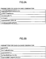
- FIG. 3A shows an example of parameters that can be configured for each CA band combination; and
- FIG. 3B shows an example of parameters that can be reported for each band in the CA band combination.
- the "dc-Support" is a parameter that indicates that the user equipment supports Dual Connectivity (which is referred to as "DC,” hereinafter).
- the "supportCSI-Proc” is a parameter indicating a CSI (Channel State Information) process number that can be supported by the user equipment.
- the "CA bandwidthclass " is a parameter indicating bandwidth classes (for each of UL/DL) that can be supported by the user equipment.
- the supported MIMO-Capability is a parameter indicating a number of MIMO layers (for each of UL/DL) that can be supported by the user equipment.
- the CSI process number is a maximum operable process number for calculating the CSI in user equipment; and it is used for reporting the CSI to a base station for CoMP (Coordinated Multi-point).
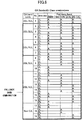
- the CA bandwidthclass is a class defined by the table (Non-Patent Document 2) of FIG. 4 ; and it indicates, for each frequency band, a bandwidth and the number of CCs that can be aggregated in the user equipment UE. For example, it is described in the standard specification that, for the frequency bands of 2 GHz (Band 1) and 1.5 GHz (Band 21), the maximum number of CCs is 1 for each band, the maximum bandwidth that can be aggregated is 100 RBs; and, for the inter-band CA with 2 CCs, 1A_21A.
- FIG. 5A and FIG. 5B a specific example of a signaling message for reporting a CA band combination is illustrated.
- FIG. 5A and FIG. 5B show one signaling message as a whole.
- the example illustrated in FIG. 5A and FIG. 5B is for the downlink only CA of 2 G + 1.5 G, which is an example for reporting the capability to perform the downlink 2 ⁇ 2 MIMO.
- four types of patterns are reported from a pattern for performing downlink CA with two bands to a pattern for using 1.5 G alone.
- FIG. 6 shows the CA band combination to be reported when the user equipment UE supports up to 3DL/3UL CA. Note that the four CA band combinations (BandCombinationParameters-r10) shown in FIG. 5A and FIG. 5B correspond, from the top, to "No. 13," “No. 14,” “No. 18,” and “No. 19” of FIG. 6 , respectively.
- a band combination lower than the 3DL/3UL that is the maximum CA capability (the number of CCs is less in any one of or both the DL and UL) is said to be a fallback band combination (Fallback band combination).
- the user equipment UE reports 19 CA band combinations in total to the base station eNB.
- "A" shown in each band of each of the CA band combinations of FIG. 6 represents the CA bandwidthclass in the band. Note that, if the CA is not to be executed (Non-CA, No. 17 - No. 19), it is specified to report it as a subset of the CA.
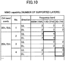
- FIG. 7 illustrates an example of reporting parameters related to the number of MIMO layers; and, for each band of each of the CA combinations, the number of the MIMO layers that can be supported by the user equipment is indicated.
- the user equipment UE is required to report all the CA band combinations supported by itself, so that the number of the CA band combinations to be reported increases, as the number of CCs to be bundled increases.
- CA has been studied where up to 32 CCs are to be bundled.
- the present invention has been achieved in view of the above-described point, and an object is to provide a technique for reducing a signal amount for reporting the capability of the CA band combination to the base station by user equipment, in a radio communication system performing carrier aggregation.
- user equipment for communicating with a base station in a radio communication system supporting carrier aggregation
- the user equipment including a generator that generates band combination information indicating one or more band combinations capable of being used for the carrier aggregation in the user equipment; and a transmitter that transmits the generated band combination information to the base station, wherein the generator generates the band combination information including highest band combination information indicating a highest band combination having a largest number of component carriers, CCs, to be combined, among the one or more band combinations capable of being used for the carrier aggregation in the user equipment.
- a base station for communicating with user equipment in a radio communication system supporting carrier aggregation, the base station including a receiver that receives, from the user equipment, band combination information indicating one or more band combinations for the carrier aggregation; and a determination unit that determines a band combination capable of being used in the user equipment depending on the one or more band combinations included in the band combination information received by the receiver, wherein, upon detecting that the band combination information includes highest band combination information indicating a highest band combination having a largest number of component carriers, CCs, to be combined, among the one or more band combinations capable of being used for the carrier aggregation in the user equipment, the determination unit determines that the user equipment is capable of using the highest band combination and all band combinations, each having a number of CCs that is less than the number of CCs in the highest band combination.
- a signal amount for the user equipment to report capability of the CA band combination to the base station can be reduced.
- FIG. 8 illustrates a configuration diagram of a radio communication system according to the embodiment of the present invention.
- the communication system according to the embodiment is a communication system based on the LTE scheme; and, as illustrated in FIG. 8 , it includes user equipment UE and a base station eNB.
- the user equipment UE and the base station eNB are capable of executing CA.
- one user equipment UE and one base station eNB are illustrated; however, this is an example, and a plurality of each of them may be included.
- the user equipment UE may be provided with a capability (DC) for simultaneously executing communication with a plurality of base stations eNBs.
- DC capability
- the user equipment UE transmits, to the base station eNB, CA band combination information indicating a combination of bands that can be supported for the base station eNB.
- CA band combination and “fallback band combination” are mainly used; and, for a case where information to be carried by a message is implied, "information indicating the CA band combination,” “information indicating the fallback band combination,” and so forth are mainly used.
- the user equipment UE when the user equipment UE supports a CA band combination and all of its fallback band combinations, the user equipment UE omits reporting information indicating the fallback band combinations, and only reports information indicating the highest CA band combination. Furthermore, for various types of parameters ( FIG. 3 ) in the CA band combination, only the various types of parameters in the highest CA band combination are to be reported.
- the highest CA band combination implies, among all the CA band combinations that can be supported by the user equipment UE, the CA band combination with the largest number of CCs to be combined both in UL and DL.
- the base station eNB determines that the user equipment UE supports, in addition to the received CA band combination, all of its fallback band combinations.
- the user equipment UE when the user equipment UE supports the Intra-band contiguous CA, and when the user equipment UE supports the CA bandwidthclass at a higher layer, it is deemed, in the embodiment, that the user equipment UE supports all the CA bandwidthclasses at lower layers. Specifically, when the user equipment UE supports all the CA bandwidthclasses of "A through F" in a predetermined frequency band, the user equipment UE reports "F” by the CA bandwidthclass with respect to the predetermined band in the CA band combination. The base station eNB determines that the user equipment UE supports all the CA bandwidthclasses of "A" through “F” in the predetermined band.
- the user equipment UE reports, in addition to the highest CA band combination, unsupported fallback band combinations to the base station eNB, in the embodiment.
- the base station eNB When the base station eNB receives information indicating a CA band combination and information indicating unsupported CA band combinations from the user equipment UE, the base station eNB determines that, in addition to the received CA band combination, all the fallback band combinations other than the unsupported fallback band combinations are supported, among all of its fallback band combinations.
- a case can be assumed where a part of the fallback band combinations includes a fallback band combination that has a parameter that is different from that of the various types of parameters of the highest CA band combination (i.e., a case where there is a difference in parameters with the highest CA band combination).
- the user equipment UE reports information indicating the fallback band combination in which only the different parameter among the various types of parameters are set.
- the base station eNB that receives information indicating the fallback band combination in which only the different parameter is set determines that the parameters that are not reported in the fallback band combination are the same as those of the highest CA band combination.
- FIG. 9 a specific example is described for a set of all 19 types of CA band combinations with the 3DL/3UL as the highest.
- CA for bundling up to 32 CCs is assumed, so that the highest CA band combination is 32DL/32UL; however, since the combination patterns are enormous, for convenience of illustration, it is described by using a set of CA band combinations with the 3DL/3UL as the highest.
- the user equipment UE supports all the 19 types of the CA band combinations; and that all the various types of parameters (the presence or absence of DC, the number of the MIMO layers, the CSI process number, etc.) are the same for respective CA band combinations.
- the user equipment UE reports, to the base station eNB, the CA band combination of No. 1 indicated by X in FIG. 9 (i.e., the highest CA band combination) and the CA band combination information in which only the various types of parameters in the CA band combination of No. 1 are set; and no reporting is performed for No. 2 through No. 19, which are the fallback band combinations of the CA band combination of No. 1.
- the base station eNB that receives the information only on the CA band combination of No. 1 among No. 1 through No. 19 from the user equipment UE determines that all of No. 1 through 19 are supported in the user equipment UE. Furthermore, for the various types of parameters in each of the CA band combinations from No. 2 through 19, a determination is made that they are the same as the various types of parameters included in the information on the CA band combination of No. 1.
- the user equipment UE transmits, to the base station eNB, the CA band combination information indicating that No. 6 and No. 10 are not supported.
- the base station eNB since the base station eNB receives, in addition to the CA band combination information of No. 1, the CA band combination information indicating that No. 6 and No. 10 are not supported, the base station eNB determines that the user equipment UE supports the highest CA band combination (No. 1) and the fallback band combinations other than No. 6 and No. 10, among the fallback band combinations No. 2 through No. 19, which are its fallback band combinations, as described above.
- a specific example is described for a case where there is a fallback band combination for the user equipment UE such that it includes a parameter that is different from that of the various types of parameters of the highest CA band combination, in a part of the fallback band combinations among all the fallback band combinations of the highest CA band combination.
- the user equipment UE supports, for each of 800 M, 1.5 G, and 2 G, 2-layer MIMO for the highest CA band combination; however, for the fallback band combination of No. 2, 4-layer MIMO is supported in 1.5 G, and for the fallback band combination of No. 4, 4-layer MIMO is supported in 2 G.
- the user equipment UE further transmits, to the base station eNB, information indicating the fallback band combination in which parameters are set that indicate that, among the bands of No. 2, 4-layer MIMO is supported in 1.5 G; and that, among the bands of No. 4, 4-layer MIMO is supported in 2G.
- the information indicating the fallback combination parameters are not set that indicate that, among the bands in No. 2, 2-layer MIMO is supported in 800 M; and that, among the bands in No. 4, 2-layer MIMO is supported in 800 M.
- the base station eNB receives, in addition to the information indicating the CA band combination of No. 1, information indicating the fallback band combination in which parameters are set that indicate that, among the bands of No. 2, 4-layer MIMO is supported in 1.5 G; and that, among the bands of No. 4, 4-layer MIMO is supported in 2G.
- the base station eNB determines that the user equipment UE supports all of No. 1 through No. 19; and that the 4-layer MIMO is supported in 1.5 G of No. 2, the 4-layer MIMO is supported in 2G of No. 4, and the other parameters are the same as the various types of parameters of No. 1.
- the user equipment UE may transmit, in addition to the information indicating the CA band combination of No. 1, information indicating the fallback band combination indicating that No. 6 and No. 10 are not supported; and information indicating the fallback band combination in which parameters are set that indicate that, among the bands of of the No. 2, the 4-layer MIMO is supported in 1.5 G, and, among the bands of No. 4, the 4-layer MIMO is supported in 2G.
- the base station eNB determines that the user equipment UE supports the highest CA band combination (No. 1) and the fallback band combinations other than No. 6 and No. 10, among its fallback band combinations (No. 2 through No. 19); and that the user equipment UE supports the 4-layer MIMO in 1.5G of No. 2, the 4-layer MIMO in 2G of No. 4, and other parameters are the same as the various types of parameters of No. 1.
- the user equipment UE reports the highest CA band combination depending on its capability; however, it may be reported by filtering with a plurality of bands instructed from the base station eNB. For example, if it is instructed by the base station eNB to report only CA band combinations that can be combined in 800 M and 1.5 G, the user equipment UE may reports the highest CA band combination; unsupported fallback band combinations; and fallback band combinations having parameter differences, among the CA band combinations that can be combined in 800 M and 1.5 G.
- the base station eNB After receiving the CA band combination information, the base station eNB determines which CA combination is to be applied among the CA combinations supported by the user equipment UE, for example, based on communication quality, etc. of each CC of the user equipment UE; and performs an operation, such as reporting (configuring) the determined CA combination to the user equipment UE.
- the base station eNB holds, for each of the highest CA band combinations, a table (example: FIG. 9 ) including the CA band combination and its fallback band combinations.
- the highest CA band combination and its fallback band combinations may be any content as long as it can be uniquely determined between the user equipment UE and the base station eNB.
- the fallback band combinations (No. 2 through No. 19) of the highest CA combination No. 1 illustrated in FIG. 9 are uniquely determined in the communication system; and the base station eNB recognizes the fallback band combinations (No. 2 through No. 19) corresponding to the highest CA combination No. 1.
- FIG. 11 shows a functional configuration diagram of the user equipment UE according to the embodiment.
- the user equipment UE includes a DL signal receiver 101; a UL signal transmitter 102; a UE capability information storage unit 103; and a generator 104.
- FIG. 11 only illustrates, in the user equipment UE, the functional units particularly related to the present invention; and functions, which are not depicted, for performing at least operation conforming to LTE are also included.
- the DL signal receiver 101 includes a function for receiving various types of downlink signals from the base station eNB, and for retrieving the higher layer information from the received physical layer signals; and the UL signal transmitter 102 includes a function for generating various types of physical layer signals from higher layer information to be transmitted from the user equipment UE, and for transmitting them to the base station eNB.
- the UE capability information storage unit 103 stores UE capability information including the CA band combinations supported by the user equipment UE itself; and various types of parameters in the CA band combinations.
- the generator 104 When the CA band combination information is to be transmitted to the base station eNB, the generator 104 refers to the UE capability information storage unit 103; and generates CA band combination information indicating the highest CA band combination, unsupported fallback band combinations, and fallback band combinations with parameter differences. Furthermore, the generator 104 instructs the UL signal transmitter 102 to transmit the generated CA band combination information to the base station eNB.
- the generator 104 may generate CA band combination information indicating, among the plurality of bands, the highest CA band combination, unsupported fallback band combinations, and fallback band combinations with parameter differences.
- the generator 104 may switch the format of the CA band combination information in accordance with an instruction from the base station eNB. For example, when the base station eNB does not support the format of the CA band combination information according to the embodiment, the CA band combination information may be generated in accordance with the usual format of the CA band combination information.
- FIG. 12 shows a functional configuration diagram of the base station eNB in the embodiment.
- the base station eNB includes a DL signal transmitter 201; a UL signal receiver 202; a CA band combination information storage unit 203; and a UE capability determination unit 204.
- FIG. 12 only illustrates, in the base station eNB, the functional units particularly related to the embodiment of the present invention; and functions, which are not depicted, for performing at least operation conforming to LTE are also included.
- the DL signal transmitter 201 includes a function for generating various types of physical layer signals from higher layer information to be transmitted from the base station eNB, and for transmitting them to the user equipment UE.
- the UL signal receiver 202 includes a function for receiving various types of uplink signals from the user equipment UE, and for retrieving the higher layer information from the received physical layer signals.
- the CA band combination information storage unit 203 stores table information including the highest CA band combination, and all of its fallback band combinations. For example, the table information, such as that of shown in FIG. 9 , is stored.
- the UE capability determination unit 204 determines, based on the CA band combination information received from the user equipment UE, the CA band combinations supported by the user equipment UE (which includes the fallback band combinations), and various types of parameters supported by the user equipment UE.
- each functional block may be implemented by a single device that is physically and/or logically coupled; or may be implemented by devices obtained by directly and/or indirectly (e.g., by wire and/or radio) connecting the physically and/or logically separated two or more devices.
- the user equipment UE and the base station eNB in the embodiment of the present invention may be function as computers for executing the processes of the information reporting method or the information receiving method according to the present invention.
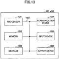
- FIG. 13 is a diagram illustrating a hardware configuration of each of the user equipment UE and the base station eNB according to the embodiment of the present invention.
- the above-described user equipment UE and the base station eNB may be physically configured as computers, each including a processor 1001; a memory 1002; a storage 1003; a communication device 1004; an input device 1005; an output device 1006; a bus 1007, and so forth.
- each of the user equipment UE and the base station eNB may be configured to include one or more of the respective devices illustrated in the figures; or may be configured without including a part of the devices.
- Each function of the user equipment UE and the base station eNB is implemented by executing an operation by the processor 1001 to control communication by the communication device 1004 and reading data from and/or writing data in the memory 1002 and the storage 1003 by loading predetermined software (program) on the hardware, such as the processor 1001 and the memory 1002.
- the processor 1001 causes an operating system to operate so as to control the entire computer.
- the processor 1001 may be formed of a central processing unit (CPU: Central Processing Unit) including an interface with a peripheral device; a control device; an arithmetic unit; a resister, and so forth.
- CPU Central Processing Unit
- the DL signal receiver 101, the UL signal transmitter 102; the UE capability information storage unit 103, and the generator 104 of the user equipment UE, and the DL signal transmitter 201, the UL signal receiver 202, the CA band combination information storage unit 203, and the UE capability determination unit 204 of the base station eNB may be implemented by the processor 1001.
- the processor 1001 reads a program (program code), a software module, or data from the storage 1003 and/or the communication device 1004 to the memory 1002; and executes various processes in accordance with these.
- a program program code
- a software module software module
- data data from the storage 1003 and/or the communication device 1004
- various processes in accordance with these.
- a program a program is used that is for causing a computer to execute at least a part of the operation described in the embodiment above.
- the DL signal receiver 101, the UL signal transmitter 102; the UE capability information storage unit 103, and the generator 104 of the user equipment UE, and the DL signal transmitter 201, the UL signal receiver 202, the CA band combination information storage unit 203, and the UE capability determination unit 204 of the base station eNB may be implemented by a control program stored in the memory 1002 and operated by the processor 1001; and the other functional blocks may be implemented similarly. It is described that the above-described various processes are implemented by the single processor 1001; however, it may be simultaneously or sequentially executed by two or more processors 1001.
- the processor 1001 may be implemented by one or more chips. Note that the program may be transmitted from a network through an electronic communication line.
- the memory 1002 is a computer readable recording medium; and may be formed of, for example, at least one of a ROM (Read Only Memory), an EPROM (Erasable Programmable ROM), an EEPROM (Electrically Erasable Programmable ROM), a RAM (Random Access Memory), and so forth.
- the memory 1002 may be referred to as a register, a cache, a main memory (main storage device), and so forth.
- the memory 1002 can store a program (program code), a software module, and so forth that can be executed for implementing the information reporting method or the information receiving method according to the embodiment of the present invention.
- the storage 1003 is a computer readable recording medium; and it can be formed of, for example, at least one of an optical disc such as a CD-ROM (Compact Disc ROM), a hard disk drive, a flexible disc, a magneto-optical disk (for example, a compact disk, a digital versatile disk, and a Blu-ray (registered trademark) disk), a smart card, a flash memory (e.g., a card, a stick, and a key drive), a floppy (registered trademark) disk, a magnetic strip, and so forth.
- the storage 1003 may be referred to as an auxiliary storage device.
- the above-described storage medium may be, for example, a database including the memory 1002 and/or the storage 1003, a server, or any other appropriate medium.
- the communication device 1004 is hardware (transmission and reception device) for executing communication between computers through a wired and/or wireless network; and is also referred to as, for example, a network device, a network controller, a network card, a communication module, and so forth.
- a network device for example, a network controller, a network card, a communication module, and so forth.
- the DL signal receiver 101 and the UL signal transmitter 102 of the user equipment UE, and the DL signal transmitter 201 and the UL signal receiver 202 of the base station eNB may be implemented by the communication device 1004.
- the input device 1005 is an input device for receiving an input from outside (e.g., a keyboard, a mouse, a microphone, a switch, a button, a sensor, etc.).
- the output device 1006 is an output device for implementing output to outside (e.g., a display, a speaker, a LED lamp, etc.). Note that the input device 1005 and the output device 1006 may be integrated (for example, a touch panel).
- the devices such as the processor 1001 and the memory 1002, are connected by the bus 1007 for communicating information.
- the bus 1007 may be formed of a single bus; or may be formed of different buses among the devices.
- the user equipment UE and the base station eNB may be formed to include hardware, such as a microprocessor, a digital signal processor (DSP: Digital Signal Processor), an ASIC (Application Specific Integrated Circuit), a PLD
- DSP Digital Signal Processor
- ASIC Application Specific Integrated Circuit
- processor 1001 may be implemented by at least one of these hardware components.
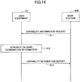
- FIG. 14 is a sequence diagram illustrating an operation of the radio communication system according to the embodiment of the present invention.
- the DL signal transmitter 201 of the base station eNB transmits a capability information request signal to the user equipment UE.
- the capability information request signal may be "UECapabilityEnquiry message," for example.
- the DL signal transmitter 201 may cause information indicating that the CA band combination information with the new format is requested to be included in the capability information request signal.
- the information may be referred to as “enhancedCAcapabilityRequest,” for example.
- the DL signal transmitter 201 of the base station eNB may cause information indicating a plurality of bands supported by the base station eNB to be included in the capability information request signal.
- the information indicating the plurality of bands supported by the base station is referred to as "requestedFrequencyBands," for example.
- the generator 104 of the user equipment UE generates the CA band combination information.
- the generator 104 When the CA band combination information with the new format is requested by the base station eNB, and when the user equipment UE itself has the capability of generating the CA band combination information with the new format, the generator 104 generates the CA band combination information with the new format.
- the generator 104 when the CA band combination information with the new format is not requested by the base station eNB, or when the user equipment UE itself does not have the capability of generating the CA band combination information with the new format (or when it may not recognize information indicating that the CA band combination information with the new format is requested), the generator 104 generates the CA band combination information with a usual format.
- the processing procedure for generating the CA band combination information with the new format by the generator 104 is specifically described.
- FIG. 16 is a flowchart illustrating a processing procedure for generating the CA band combination information. Furthermore, FIG. 17 and FIG. 18 show a specific example of the CA band combination information.
- the generator 104 causes information indicating the highest CA band combination among the CA band combinations supported by the user equipment UE itself to be included in the CA band combination information.
- “information indicating the highest CA band combination” may be referred to as "BandCombinationParametersParent,” as shown in FIG. 17 and FIG. 18 .
- the generator 104 confirms whether there exists a fallback band combination not supported by the user equipment UE, among all the fallback band combinations of the highest CA band combination. If there is an unsupported fallback band combination, the process proceeds to step S23; and if not, the process proceeds to step S24.
- the generator 104 causes information indicating the unsupported fallback band combination to be included in the CA band combination information.
- information indicating the unsupported fallback band combination may be referred to as “non-SupportedBandCombinationChild,” as shown in FIG. 17 and FIG. 18 .
- the generator confirms whether there exists a fallback band combination including parameters that are different from the various types of parameters in the highest CA band combination, among the supported fallback band combinations. If there is a fallback band combination including parameters that are different from the various types of parameters in the highest CA band combination, the process proceeds to step S25; and if not, the process of generating the CA band combination information is terminated.
- the generator 204 causes information on the fallback band combination in which only the parameter, among the various types of parameters, that is different from that of the highest CA band combination is set to be included in the CA band combination information.
- “information on the fallback band combination in which only the parameter, among the various types of parameters, that is different from that of the highest CA band combination is set” may be referred to as "supportedBandCombinationChildExt,” as shown in FIG. 17 and FIG. 18 .
- the generator 104 may set, in addition to the different parameter, a part of the parameters (e.g., the number of MIMO layers, etc.) of the parameters that are the same as those of the highest CA band combination to be included in the CA band combination information, instead of only setting the parameter, among the various types of parameters, that is different from that of the highest CA band combination in "information on the fallback band combination in which only the parameter, among the various types of parameters, that is different from that of the highest CA band combination is set.” Furthermore, at step S24 and step S25, for the fallback band combination including the parameter, among the various types of parameters, that is different from that of the highest CA band combination, the generator 104 may cause information on the fallback band combination in which all the parameters (i.e., all the different parameter and the parameters with the same values) are set to be included in the CA band combination information. In this manner, a likelihood that the base station eNB erroneously recognizes the capability of the user equipment UE can be reduced.
- the generator 104 may cause information on the
- the generator 104 causes, in the processing procedures from step S21 through step S25, information indicating the highest CA band combination among the reported plurality of bands; information indicating the unsupported fallback band combinations; and information on fallback band combinations in which only the parameter, among the various types of parameters, that is different from that of the highest CA band combination is set to be included in the CA band combination information.
- the generator 104 may generate the CA band combination information that is filtered by the plurality of bands reported from the base station eNB. Referring back to FIG. 14 , the description is continued.
- the UL signal transmitter 102 of the user equipment UE transmits a capability information report signal including the generated CA band combination information to the base station eNB.
- the capability information report signal may be, for example, "UECapabilityInformation message.”
- the UE capability determination unit 204 of the base station eNB determines the CA band combinations supported by the user equipment UE (which includes the fallback band combinations) and various types of parameters supported by the user equipment UE, based on the CA band combination information included in the received capability information.
- the UE capability determination unit 204 determines that the user equipment UE supports the highest CA band combination and all of its fallback band combinations.
- the UE capability determination unit 204 determines that the user equipment UE supports the highest CA band combination and, among all of its fallback band combinations, the fallback band combinations other than the unsupported fallback band combinations.
- the UE capability determination unit 204 determines that the user equipment UE supports the highest CA band combination and all of its fallback band combinations; and determines that a part of the fallback band combinations supports the parameter that is different from that of the highest CA band combination.
- the UE capability determination unit 204 determines that the user equipment UE supports the highest CA band combination and, among all of its fallback band combinations, the fallback band combinations other than the unsupported fallback band combinations; and further determines that a part of the fallback band combinations supports the parameter that is different from that of the highest CA band combination.
- the base station eNB transmits a capability information request signal (UECapabilityEnquiry) including "requestReducedFormat” and "requestSkipFallbackComb.”
- UECapabilityEnquiry a capability information request signal
- the "equestReducedFormat” indicates a command that the CA band combination is to be reported by using the format (supportedBandCombinationReduced-r13) specified in Release 13, instead of the usual format (supportedBandCombination-r10).
- the "requestSkipFallbackComb” indicates a command that the fallback band combinations are to be omitted, and that only the highest CA band combination is to be reported.
- the user equipment UE causes the CA band combination information including the information indicating the highest CA band combination to be included in the capability information report signal (UECapabilityInformation); and transmits it to the base station eNB.
- the user equipment UE if there exists, among the supported fallback band combinations, a fallback band combination including a parameter that is different from that of the various types of parameters of the highest CA band combination, the user equipment UE causes "information indicating that there exists the fallback band combination including the parameter that is different from that of the various types of parameters of the highest CA band combination (differentFallbackSupported)" to be included in the capability information report signal.
- the base station eNB that receives the capability information report signal including the "differentFallbackSupported" desires to obtain detailed information on the fallback band combination including the parameter that is different from that of the various types of parameters of the highest CA band combination, the capability information request signal (UECapabilityEnquiry) is transmitted again.
- the base station eNB transmits, at step S33, the capability information request signal to the user equipment UE without including the "requestReducedFormat” and the "requestSkipFallbackComb.” Namely, the base station eNB requests the CA band combination information with the usual format (supportedBandCombination-r10) (i.e., the CA band combination information including all the CA band combinations) from the user equipment UE.
- supportedBandCombination-r10 i.e., the CA band combination information including all the CA band combinations
- the user equipment UE transmits, to the base station eNB, the capability report signal including the CA band combination information with the usual format.
- the user equipment UE if there exists, among the fallback band combinations supported by the user equipment UE, a fallback band combination including a parameter that is different from that of the various types of parameters of the highest CA band combination, the user equipment UE is to report the CA band combination information with the usual format to the base station eNB. Since all the CA band combinations are included in the CA band combination information with the usual format, there is a problem that the signaling amount becomes enormous.
- the modified example 1 proposes a scheme that can efficiently report, to the base station eNB, the fallback band combination including the different parameter.
- Functional configurations of the user equipment UE and the base station eNB according to the modified example 1 are described.
- the functional configurations of the user equipment UE and the base station eNB according to the modified example 1 are the same as those of FIG. 11 and FIG. 12 , respectively, so that only the functional units that are different from those of the basic example are described.
- the generator 104 If there exists, among parameters corresponding to CA band combinations that can be used for CA in the user equipment UE, a fallback band combination including a parameter that is different from the parameter corresponding to the highest CA band combination, the generator 104 generates the CA band combination information further including information indicating that there exists the fallback band combination including the different parameter.
- the generator 104 when the base station eNB instructs to report, among fallback combinations of a predetermined CA band combination, a fallback band combination including a parameter that is different from the parameter corresponding to the predetermined CA band combination, the generator 104 generates the CA band combination information including information indicating the fallback band combination including the parameter that is different from the parameter corresponding to the predetermined CA band combination, among the fallback band combinations of the predetermined CA band combination.
- the UE capability determination unit 204 recognizes that the user equipment UE is provided with capability of supporting the fallback band combination including the parameter that is different from the parameter corresponding to the highest CA band combination.
- the DL signal transmitter 201 may transmit, to the user equipment UE, a signal for instructing to report, among the fallback combinations of the predetermined CA band combination, the fallback band combination including the parameter that is different from the parameter corresponding to the predetermined CA band combination.
- FIG. 21 is a sequence diagram illustrating an operation of the radio communication system according to the modified example 1 of the present invention. Since the processing procedure of step S41 is the same as that of step S31 of FIG. 20 , the description is omitted.
- the generator 104 of the user equipment UE generates the CA band combination information including information indicating the highest CA band combination. Furthermore, if there exists, among the supported fallback band combinations, a fallback band combination including a parameter that is different from that of the various types of parameters of the highest CA band combination, the generator 104 generates the CA band combination information including information indicating the highest CA band combination and "information indicating that there exists the fallback band combination including the parameter that is different from that of the various types of parameters of the highest CA band combination(differentFallbackSupported) .”
- the UL signal transmitter 102 of the user equipment UE transmits the capability information report signal (UECapabilityInformation) including the generated CA band combination information to the base station eNB.
- UECapabilityInformation capability information report signal
- step S42 and step S43 correspond to step S32 of FIG. 20 .
- the DL signal transmitter of the base station eNB transmits, at step S44, the capability information request signal (UECapabilityEnquiry) again.
- the DL signal transmitter of the base station eNB causes "a command for requesting to report, among the fallback combinations of the predetermined CA band combination, the fallback band combination including the parameter that is different from the parameter corresponding to the predetermined CA band combination" to be included in the capability request signal; and transmits it to the user equipment UE.
- the command may be referred to as "requestDiffFallbackCombList.”
- the predetermined CA band combination is the same as the highest CA band combination included in the capability information report signal reported from the user equipment UE; however, it is not necessarily limited to this, and it includes the CA band combination, reporting of which is desired by the base station eNB.
- the predetermined CA band combination may be, among the plurality of the highest CA band combinations, one or more highest CA band combinations, reporting of which are desired by the base station eNB.
- the predetermined CA band combination may be, among the fallback combinations of the highest CA band combination reported from the user equipment UE in the processing procedure of step S43, one or more highest CA band combinations supported by the base station eNB, for example.
- the highest CA band combination reported from the user equipment UE is 1A-3A-19A-42A; and that the CA band combinations supported by the base station eNB are only 1A-3A-19A and its fallback combinations and 3A-19A-42A and its fallback combinations, for example.
- the base station eNB may report, instead of 1A-3A-19A-42A, 1A-3A-19A and 3A-19A-42A, as the predetermined CA band combinations. In this manner, the base station eNB can narrow down the CA band combinations to be reported by the user equipment UE to the CA band combinations, reporting of which is desired by the base station eNB itself; and the signaling amount can be reduced.
- the capability information request signal to be transmitted at step S44 may further include a command (requestReducedFormat) such that the CA band combination is to be reported by using the format (supportedBandCombinationReduced-r13) specified in Release 13.
- a command (requestReducedFormat) such that the CA band combination is to be reported by using the format (supportedBandCombinationReduced-r13) specified in Release 13.
- step S45 if the capability information request signal received at step S44 includes "a command requesting to report, among the fallback combinations of the predetermined CA band combination, the fallback band combination including the parameter that is different from the parameter of the predetermined CA band combination," the generator 104 of the user equipment UE generates the CA band combination information including "information indicating the fallback band combination including the parameter that is different from the parameter corresponding to the predetermined CA band combination.”
- the "information indicating the fallback band combination including the parameter that is different from the parameter corresponding to the predetermined CA band combination" may be information on the CA band combination that only includes the parameter that is different from the parameters corresponding to the predetermined CA band combination. For example, suppose that the user equipment UE supports, in the CA band combination of 19A-42A, which is a fallback combination of 1A-3A-19A-42A, 2-layer MIMO and 4-layer MIMO only in the band of 19A and only the 2-layer MIMO for all of the bands of 42A and the bands of other CA band combinations.
- the generator 104 of the user equipment UE may generate the CA band combination information only indicating that, in the CA band combination of 19A-42A, 4-layer MIMO is supported in the bands of 19A, and 2-layer MIMO is supported in the bands of 42A.
- the CA band combination information may not be generated that indicates that, in the CA band combination of 19A-42A, 2-layer MIMO is supported in the bands of 19A, and 2-layer MIMO is supported in the bands of 42A.
- information indicating the highest CA band combination of the fallback band combination including the parameter that is different from the parameter corresponding to the predetermined CA band combination may be included, as an echo back to the base station eNB, in the CA band combination information generated at step S45.
- the information indicating the highest CA band combination may be referred to as "requestedDiffFallbackCombList.”
- the base station eNB may recognize that, for which range of the CA band combinations (namely, the range of the reported highest CA band combination and its fallback combinations), the CA band combination including the different parameter (the fallback combination) is reported from the user equipment UE by using only the capability information report signal reported from the UE without being conscious of the predetermined CA band combination included in the capability information request signal by itself.
- the information indicating the highest CA band combination may more specifically be information indicating the CA band combination that is the same as the "predetermined CA band combination" included in the capability request signal received at step S44. Furthermore, it is not limited to this, and the information indicating the highest CA band combination may not be the information indicating the CA band combination that is the same as the "predetermined CA band combination” included in the capability request signal received at step S44, as long as it is information indicating the CA band combination corresponding to a higher layer of the fallback band combination including the parameter that is different from the parameter corresponding to the predetermined CA band combination. In this manner, the user equipment UE can report only a part of the fallback combinations, among the fallback combinations, each including a parameter that is different from the parameter corresponding to the predetermined CA band combination.
- the UL signal transmitter 102 of the user equipment UE transmits, to the base station eNB, a capability information report signal including the CA band combination information generated at step S45.
- the UE capability determination unit 204 of the base station eNB can recognize the fallback band combination including the parameter that is different from the parameter corresponding to the predetermined CA band combination.
- the generator 104 causes "information indicating the highest CA band combination" in the reported plurality of bands, and "information indicating the fallback band combination including the parameter that is different from the parameter corresponding to the predetermined CA band combination" in the reported plurality of bands to be included in the CA band combination information.
- the generator 104 may generate the CA band combination information that is filtered by the plurality of bands reported from the base station eNB.
- FIG. 22 is a diagram showing a specification change example illustrating the operation of the RRC layer when the user equipment UE generates the capability information report, which is described in step S44 through step S46 of FIG. 21 .
- UECapabilityEnquiry message includes requestDiffFallbackCombList
- the user equipment UE supports the format specified in Release 13 (requestReducedFormat), supports the operation illustrated in the modified example 1 (diffFallbackCombReport), and receives the capability information request (UECapabilityEnquiry) including "a command requesting to report, among the fallback combinations of a predetermined CA band combination, the fallback band combination including the parameter that is different from the parameter corresponding to the predetermined CA band combination" (requestDiffFallbackCombList), the user equipment UE performs the following operation.
- the user equipment UE first, as described as "6> for each CA band combination indicated in requestDiffFallbackCombList, include its fallback band combinations for which the capabilities are different from the band combination indicated in requestDiffFallbackCombList," the user equipment UE generates a capability information report (UECapabilityInformation) including, for each of the fallback band combinations of a predetermined CA band combination instructed from the base station eNB (one or more CA band combinations included in the "requestDiffFallbackCombList”), a fallback band combination including a parameter (Capability: Capability) that is different from that of the predetermined CA band combination.
- UECapabilityInformation including, for each of the fallback band combinations of a predetermined CA band combination instructed from the base station eNB (one or more CA band combinations included in the "requestDiffFallbackCombList"
- the user equipment UE causes the highest CA band combination (CA band combinations with the highest supported number of DL and UL carriers) of the fallback combination including the different parameter (Capability: Capability) to be included in the "requestedDiffFallbackCombList.”
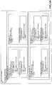
- FIG. 23A and FIG. 23B are diagrams showing a specification change example of the capability information request transmitted at step S44 of FIG. 21 .
- FIG. 23A shows a specification change example of the UECapabilityEnquiry message; and
- FIG. 23B shows descriptions of the fields included in the UECapabilityEnquiry message.
- the "command for requesting to report, among fallback combinations of a predetermined CA band combination, the fallback band combination including the parameter that is different from the parameter corresponding to the predetermined CA band combination” described in step S44 of FIG. 21 corresponds to the "requestDiffFallbackCombList" in FIG. 23A and FIG. 23B .
- FIG. 24 is a diagram illustrating a specification change example (version 1) of the capability information report that is transmitted at step S46 of FIG. 21 .
- the example of FIG. 24 shows the specification change example of a case of extending the existing signaling (UE-EUTRA-Capability).
- the "information indicating the fallback band combination including the parameter that is different from the parameter corresponding to the predetermined CA band combination” described in step S46 of FIG. 21 corresponds to the "supportedBandCombinationReduced” of FIG. 24 . Furthermore, the "information indicating the highest CA band combination of the fallback band combination including the parameter that is different from the parameter corresponding to the predetermined CA band combination, as an echo back to the base station eNB" described in step S46 of FIG. 21 corresponds to the "requestedDiffFallbackCombList" of FIG. 24 . Furthermore, the "diffFallbackCombReport" of FIG. 24 is information indicating that the user equipment UE supports the operation illustrated in the modified example 1, and it is configured as an echo back to the base station eNB.
- FIG. 25 and FIG. 26 are diagrams showing a specification change example (version 2) of the capability information report that is transmitted at step S46 of FIG. 21 .
- the example of FIG. 25 and FIG. 26 shows the specification change example for specifying a new "UECapablityInformation" message.
- information elements essential to the existing signaling UE-EUTRA-Capability
- the CA band combination information including the "information indicating the fallback band combination including parameter that is different from the parameter corresponding to the predetermined CA band combination” described in step S46 of FIG. 21 corresponds to the "supportedBandCombinationReduced” of FIG. 25 .
- the "information indicating the highest CA band combination of the fallback band combination including the parameter that is different from the parameter corresponding to the predetermined CA band combination, as an echo back to the base station eNB" described in S46 of FIG. 21 corresponds to the "requestedDiffFallbackCombList" of FIG. 25 .
- the "diffFallbackCombReport" of FIG. 26 is information indicating that the user equipment UE supports the operation illustrated in the modified example 1, and it is set as an echo back to the base station eNB.
- the signaling amount for reporting, by the user equipment UE, the fallback band combination including the parameter that is different from that of the various types of parameters of the highest CA band combination to the base station eNB can be reduced compared with the signaling amount in the processing procedure specified in Release 13.
- user equipment for communicating with a base station in a radio communication system supporting carrier aggregation, the user equipment including a generator that generates band combination information indicating one or more band combinations capable of being used for the carrier aggregation in the user equipment; and a transmitter that transmits the generated band combination information to the base station, wherein the generator generates the band combination information including highest band combination information indicating a highest band combination having a largest number of component carriers, CCs, to be combined, among the one or more band combinations capable of being used for the carrier aggregation in the user equipment.
- a technique is provided that is for reducing a signal amount for reporting, by the user equipment, the capability of the CA band combination to the base station in the radio communication system performing carrier aggregation.
- the generator may generate the band combination information further including exceptional band combination information indicating the band combination including the different parameter.
- the user equipment UE reports only the unsupported fallback band combination to the base station eNB, so that the signal amount for reporting the capability of the CA band combination to the base station can be reduced.
- the generator may generate the band combination information including highest band combination information indicating a highest band combination having a largest number of CCs to be combined among the plurality of bands. In this manner, even if there exists a fallback band combination with a parameter that is different from that of the highest CA band combination (there is a difference in parameters), it suffices if the user equipment UE reports only the fallback band combination with the different parameter to the base station eNB, so that the signal amount for reporting the capability of the CA band combination to the base station can be reduced.
- the generator may generate the band combination information; and, upon not being instructed by the base station, the generator may generate band combination information in accordance with a usual format. Depending on the capability of the base station eNB, the format of the CA band combination information can be switched.
- the generator may generate, instead of the highest band combination information, the band combination information including information indicating the band combination including the parameter that is different from the parameter corresponding to the predetermined band combination, among all the band combinations with the numbers of CCs that are less than the number of CCs of the predetermined band combination. In this manner, if there exists a fallback band combination including a parameter that is different from that of the various types of parameters of the highest CA band combination, the fallback band combination including the different parameter can be efficiently reported to the base station.
- a base station for communicating with user equipment in a radio communication system supporting carrier aggregation, the base station including a receiver that receives, from the user equipment, band combination information indicating one or more band combinations for the carrier aggregation; and a determination unit that determines a band combination capable of being used in the user equipment depending on the one or more band combinations included in the band combination information received by the receiver, wherein, upon detecting that the band combination information includes highest band combination information indicating a highest band combination having a largest number of component carriers, CCs, to be combined, among the one or more band combinations capable of being used for the carrier aggregation in the user equipment, the determination unit determines that the user equipment is capable of using the highest band combination and all band combinations, each having a number of CCs that is less than the number of CCs in the highest band combination.
- a technique is provided that is for reducing a signal amount for reporting, by the user equipment, the capability of the CA band combination to the base
- an information reporting method to be executed by user equipment for communicating with a base station in a radio communication system supporting carrier aggregation, the information reporting method including a generation step of generating band combination information indicating one or more band combinations capable of being used for the carrier aggregation in the user equipment; and a transmission step of transmitting the generated band combination information to the base station, wherein the generation step generates the band combination information including highest band combination information indicating a highest band combination having a largest number of component carriers, CCs, to be combined, among the one or more band combinations capable of being used for the carrier aggregation in the user equipment.
- a technique is provided that is for reducing a signal amount for reporting, by the user equipment, the capability of the CA band combination to the base station in the radio communication system performing carrier aggregation.
- an information receiving method to be executed by a base station for communicating with user equipment in a radio communication system supporting carrier aggregation, the information receiving method including a reception step of receiving, from the user equipment, band combination information indicating one or more band combinations for the carrier aggregation; and a determination step of determining a band combination capable of being used in the user equipment depending on the one or more band combinations included in the band combination information received by the receiver, wherein, upon detecting that the band combination information includes highest band combination information indicating a highest band combination having a largest number of component carriers, CCs, to be combined, among the one or more band combinations capable of being used for the carrier aggregation in the user equipment, the determination step determines that the user equipment is capable of using the highest band combination and all band combinations, each having a number of CCs that is less than the number of CCs in the highest band combination.
- a technique is provided that is for reducing a signal amount for reporting, by the user equipment, the capability of
- the configuration of each of the devices (the user equipment UE / the base station eNB) described in the embodiment may be a configuration that is implemented by executing a program by the CPU (processor) in the device including the CPU and the memory; a configuration that is implemented by hardware provided with a logic for the process described in the embodiment, such as a hardware circuit; or a mixture of programs and hardware.
- a boundary of a functional unit or a processor in the functional block diagrams may not necessarily correspond to a boundary of a physical component.
- An operation by a plurality of functional units may be physically executed by a single component, or an operation of a single functional unit may be physically executed by a plurality of components.
- the order can be replaced, provided that there is no contradiction.
- the user equipment UE and the base station eNB are described by using the functional block diagrams; however, such devices may be implemented in hardware, software, or combinations thereof.
- Each of the software to be operated by the processor included in the user equipment UE in accordance with the embodiment of the present invention, and the software to be operated by the processor included in the base station eNB in accordance with the embodiment of the present invention may be stored in any appropriate storage medium, such as a random access memory (RAM), a flash memory, a read-only memory (ROM), an EPROM, an EEPROM, a register, a hard disk drive (HDD), a removable disk, a CD-ROM, a database, a server, and so forth.
Landscapes
- Engineering & Computer Science (AREA)
- Signal Processing (AREA)
- Computer Networks & Wireless Communication (AREA)
- Quality & Reliability (AREA)
- Power Engineering (AREA)
- Mobile Radio Communication Systems (AREA)
Claims (5)
- Equipement utilisateur pour communiquer avec une station de base dans un système de communication radio prenant en charge une agrégation de porteuses, l'équipement utilisateur comprenant :un générateur (104) configuré pour générer, lorsqu'il est donné instruction par la station de base et lors d'une détection qu'une pluralité de bandes prises en charge par la station de base est rapportée à partir de la station de base, des informations de combinaisons de bandes indiquant une ou plusieurs combinaisons de bandes en mesure d'être utilisées pour l'agrégation de porteuses dans l'équipement utilisateur ;dans lequel le générateur (104) est configuré pour générer les informations de combinaisons de bandes incluant des informations de combinaisons de bandes la plus élevée correspondant à la combinaison de bandes ayant le plus grand nombre de porteuses composantes, CC, à combiner et excluant des informations indiquant les combinaisons de bandes de repli, parmi les une ou plusieurs combinaisons de bandes en mesure d'être utilisées pour l'agrégation de porteuses dans l'équipement utilisateur ; etlorsqu'il n'est pas donné instruction par la station de base, le générateur (104) est configuré en outre pour générer des informations de combinaisons de bandes conformément à LTE Ver. 10 ; etun émetteur (102) configuré pour transmettre les informations de combinaisons de bandes générées à la station de base.
- Equipement utilisateur selon la revendication 1, dans lequel, lorsqu'il est donné instruction par la station de base de rapporter, parmi toutes les combinaisons de bandes avec des nombres de CC qui sont inférieurs à un nombre de CC d'une combinaison de bandes prédéterminée, une combinaison de bandes incluant un paramètre qui est différent d'un paramètre correspondant à la combinaison de bandes prédéterminée, le générateur (104) est configuré en outre pour générer, à la place des informations de combinaison de bandes la plus élevée, les informations de combinaisons de bandes incluant des informations indiquant la combinaison de bandes incluant le paramètre qui est différent du paramètre correspondant à la combinaison de bandes prédéterminée, parmi toutes les combinaisons de bandes avec les nombres de CC qui sont inférieurs au nombre de CC de la combinaison de bandes prédéterminée.
- Station de base pour communiquer avec un équipement utilisateur dans un système de communication radio prenant en charge une agrégation de porteuses, la station de base comprenant :un émetteur (201) configuré pour rapporter à l'équipement utilisateur une pluralité de bandes prises en charge par la station de base ;un récepteur (202) configuré pour recevoir à partir de l'équipement utilisateur, lorsque l'équipement utilisateur reçoit instruction et lors du rapport de la pluralité de bandes prise en charge, des informations de combinaisons de bandes indiquant une ou plusieurs combinaisons de bandes en mesure d'être utilisées pour l'agrégation de porteuses ; etune unité de détermination (204) configurée pour déterminer une combinaison de bandes en mesure d'être utilisée dans l'équipement utilisateur en fonction des une ou plusieurs combinaisons de bandes incluses dans les informations de combinaisons de bandes reçues par le récepteur,dans laquelle, lors de la détection que les informations de combinaisons de bandes incluent des informations de combinaison de bandes la plus élevée correspondant à la combinaison de bandes la plus élevée ayant le plus grand nombre de porteuses composantes, CC, à combiner et excluant des informations indiquant les combinaisons de bandes de repli, parmi les une ou plusieurs combinaisons de bandes en mesure d'être utilisées pour l'agrégation de porteuses dans l'équipement utilisateur, l'unité de détermination (204) est configurée pour déterminer que l'équipement utilisateur est capable d'utiliser la combinaison de bandes la plus élevée et toutes les combinaisons de bandes ayant un nombre de CC qui est inférieur au nombre de CC dans la combinaison de bandes la plus élevée et étant incluses dans la combinaison de bandes la plus élevée ;dans laquelle le récepteur (202) est configuré en outre pour recevoir à partir de l'équipement utilisateur, lorsque l'équipement utilisateur ne reçoit pas instruction, des informations de combinaisons de bandes conformément à LTE Ver. 10.
- Procédé de rapport d'informations destiné à être exécuté par un équipement utilisateur pour communiquer avec une station de base dans un système de communication radio prenant en charge une agrégation de porteuses, le procédé de rapport d'informations comprenant :une étape de génération pour générer, lorsqu'il est donné instruction par la station de base et lors d'une détection qu'une pluralité de bandes prises en charge par la station de base est rapportée à partir de la station de base, des informations de combinaisons de bandes indiquant une ou plusieurs combinaisons de bandes en mesure d'être utilisées pour l'agrégation de porteuses dans l'équipement utilisateur ;dans lequel l'étape de génération génère les informations de combinaisons de bandes incluant des informations de combinaison de bandes la plus élevée correspondant à la combinaison de bandes la plus élevée ayant le plus grand nombre de porteuses composantes, CC, à combiner et excluant des informations indiquant les combinaisons de bandes de repli, parmi les une ou plusieurs combinaisons de bandes en mesure d'être utilisées pour l'agrégation de porteuses dans l'équipement utilisateur ; etlorsqu'il n'est pas donné instruction par la station de base, l'étape de génération génère des informations de combinaisons de bandes conformément à LTE Ver. 10 ; etune étape de transmission pour transmettre les informations de combinaisons de bandes générées à la station de base.
- Procédé de réception d'informations destiné à être exécuté par une station de base pour communiquer avec un équipement utilisateur dans un système de communication radio prenant en charge une agrégation de porteuses, le procédé de réception d'informations comprenant :une étape de rapport pour rapporter à l'équipement utilisateur une pluralité de bandes prises en charge par la station de base ;une étape de réception pour recevoir, à partir de l'équipement utilisateur, lorsque l'équipement utilisateur reçoit instruction et lors du rapport de la pluralité de bandes prise en charge, des informations de combinaisons de bandes indiquant une ou plusieurs combinaisons de bandes pour l'agrégation de porteuses ; etune étape de détermination pour déterminer une combinaison de bandes en mesure d'être utilisée dans l'équipement utilisateur en fonction des une ou plusieurs combinaisons de bandes incluses dans les informations de combinaisons de bandes,dans lequel, lors de la détection que les informations de combinaisons de bandes incluent des informations de combinaison de bandes la plus élevée correspondant à la combinaison de bandes la plus élevée ayant le plus grand nombre de porteuses composantes, CC, à combiner et excluant des informations indiquant les combinaisons de bandes de repli, parmi les une ou plusieurs combinaisons de bandes en mesure d'être utilisées pour l'agrégation de porteuses dans l'équipement utilisateur, l'étape de détermination détermine que l'équipement utilisateur est capable d'utiliser la combinaison de bandes la plus élevée et toutes les combinaisons de bandes, chacune ayant un nombre de CC qui est inférieur au nombre de CC dans la combinaison de bandes la plus élevée et étant incluses dans la combinaison de bandes la plus élevée,dans lequel, lorsque l'équipement utilisateur ne reçoit pas instruction, l'étape de réception inclut la réception à partir de l'équipement utilisateur d'informations de combinaisons de bandes conformément à LTE Ver. 10.
Priority Applications (1)
| Application Number | Priority Date | Filing Date | Title |
|---|---|---|---|
| EP20160387.5A EP3697156B1 (fr) | 2015-08-13 | 2016-08-03 | Équipement utilisateur, station de base, procédé de rapport d'informations et procédé de réception d'informations |
Applications Claiming Priority (2)
| Application Number | Priority Date | Filing Date | Title |
|---|---|---|---|
| JP2015159995 | 2015-08-13 | ||
| PCT/JP2016/072730 WO2017026334A1 (fr) | 2015-08-13 | 2016-08-03 | Équipement d'utilisateur, station de base, procédé de notification d'informations et procédé de réception d'informations |
Related Child Applications (2)
| Application Number | Title | Priority Date | Filing Date |
|---|---|---|---|
| EP20160387.5A Division EP3697156B1 (fr) | 2015-08-13 | 2016-08-03 | Équipement utilisateur, station de base, procédé de rapport d'informations et procédé de réception d'informations |
| EP20160387.5A Division-Into EP3697156B1 (fr) | 2015-08-13 | 2016-08-03 | Équipement utilisateur, station de base, procédé de rapport d'informations et procédé de réception d'informations |
Publications (3)
| Publication Number | Publication Date |
|---|---|
| EP3337264A1 EP3337264A1 (fr) | 2018-06-20 |
| EP3337264A4 EP3337264A4 (fr) | 2018-08-01 |
| EP3337264B1 true EP3337264B1 (fr) | 2020-05-27 |
Family
ID=57983174
Family Applications (2)
| Application Number | Title | Priority Date | Filing Date |
|---|---|---|---|
| EP16835031.2A Active EP3337264B1 (fr) | 2015-08-13 | 2016-08-03 | Équipement d'utilisateur, station de base, procédé de notification d'informations et procédé de réception d'informations |
| EP20160387.5A Active EP3697156B1 (fr) | 2015-08-13 | 2016-08-03 | Équipement utilisateur, station de base, procédé de rapport d'informations et procédé de réception d'informations |
Family Applications After (1)
| Application Number | Title | Priority Date | Filing Date |
|---|---|---|---|
| EP20160387.5A Active EP3697156B1 (fr) | 2015-08-13 | 2016-08-03 | Équipement utilisateur, station de base, procédé de rapport d'informations et procédé de réception d'informations |
Country Status (8)
| Country | Link |
|---|---|
| US (1) | US10476702B2 (fr) |
| EP (2) | EP3337264B1 (fr) |
| JP (2) | JPWO2017026334A1 (fr) |
| CN (1) | CN107251630B (fr) |
| ES (2) | ES2967112T3 (fr) |
| FI (1) | FI3697156T3 (fr) |
| HU (1) | HUE050621T2 (fr) |
| WO (1) | WO2017026334A1 (fr) |
Families Citing this family (13)
| Publication number | Priority date | Publication date | Assignee | Title |
|---|---|---|---|---|
| US10660025B2 (en) | 2016-06-23 | 2020-05-19 | Htc Corporation | Device and method for handling dual cellular system aggregation |
| US10158477B2 (en) * | 2016-07-28 | 2018-12-18 | At&T Mobility Ii Llc | Method and apparatus for defining carrier aggregation group sets |
| US10939445B2 (en) * | 2017-03-31 | 2021-03-02 | Intel IP Corporation | Methods and apparatus to announce channel capabilities in wireless communication systems |
| CN109951895B (zh) * | 2017-12-20 | 2021-01-29 | 华为技术有限公司 | 上报用户设备的能力信息的方法和装置 |
| CN111630892B (zh) * | 2018-01-25 | 2023-10-27 | 株式会社Ntt都科摩 | 用户装置以及基站装置 |
| KR102598542B1 (ko) * | 2018-03-08 | 2023-11-06 | 삼성전자주식회사 | 반송파 집성을 위한 반송파 조합 송신 방법 및 이를 위한 전자 장치 |
| US11930560B2 (en) | 2019-02-21 | 2024-03-12 | Ntt Docomo, Inc. | User apparatus and base station apparatus |
| JPWO2020235318A1 (fr) * | 2019-05-17 | 2020-11-26 | ||
| US12101797B2 (en) | 2019-07-18 | 2024-09-24 | Samsung Electronics Co., Ltd. | Methods and systems for use of carrier aggregation capability |
| US11601946B2 (en) * | 2020-02-05 | 2023-03-07 | Samsung Electronics Co., Ltd. | Multi-TRP and URLLC capability signaling |
| CN111432487B (zh) | 2020-02-13 | 2021-02-23 | 华为技术有限公司 | 频带信息上报方法及相关设备 |
| JP7443488B2 (ja) * | 2020-02-27 | 2024-03-05 | 株式会社Nttドコモ | 端末、無線基地局及び無線通信方法 |
| US12003438B2 (en) * | 2021-08-04 | 2024-06-04 | Qualcomm Incorporated | Aggregate component carrier for full-duplex operation |
Family Cites Families (5)
| Publication number | Priority date | Publication date | Assignee | Title |
|---|---|---|---|---|
| TWI445368B (zh) * | 2010-06-25 | 2014-07-11 | Htc Corp | 適用於無線通訊能力傳訊之行動通訊裝置 |
| CN102457352B (zh) * | 2010-11-04 | 2014-05-07 | 华为技术有限公司 | 一种聚合载波中rf能力上报的方法、设备和系统 |
| JP5802480B2 (ja) * | 2011-08-12 | 2015-10-28 | 株式会社Nttドコモ | 移動通信方法及び無線基地局 |
| KR20130126427A (ko) * | 2012-05-11 | 2013-11-20 | 주식회사 팬택 | 다중 요소 반송파 시스템에서 단말의 성능정보의 전송장치 및 방법 |
| JP6292573B2 (ja) | 2014-02-27 | 2018-03-14 | ホシザキ株式会社 | 洗浄機 |
-
2016
- 2016-08-03 HU HUE16835031A patent/HUE050621T2/hu unknown
- 2016-08-03 EP EP16835031.2A patent/EP3337264B1/fr active Active
- 2016-08-03 ES ES20160387T patent/ES2967112T3/es active Active
- 2016-08-03 CN CN201680009308.XA patent/CN107251630B/zh active Active
- 2016-08-03 JP JP2017534379A patent/JPWO2017026334A1/ja active Pending
- 2016-08-03 EP EP20160387.5A patent/EP3697156B1/fr active Active
- 2016-08-03 FI FIEP20160387.5T patent/FI3697156T3/fi active
- 2016-08-03 US US15/541,729 patent/US10476702B2/en active Active
- 2016-08-03 WO PCT/JP2016/072730 patent/WO2017026334A1/fr active Application Filing
- 2016-08-03 ES ES16835031T patent/ES2801148T3/es active Active
-
2018
- 2018-04-27 JP JP2018086434A patent/JP6646099B2/ja active Active
Non-Patent Citations (1)
| Title |
|---|
| None * |
Also Published As
| Publication number | Publication date |
|---|---|
| FI3697156T3 (fi) | 2023-12-12 |
| EP3337264A1 (fr) | 2018-06-20 |
| US10476702B2 (en) | 2019-11-12 |
| ES2967112T3 (es) | 2024-04-26 |
| CN107251630A (zh) | 2017-10-13 |
| ES2801148T3 (es) | 2021-01-08 |
| CN107251630B (zh) | 2021-09-21 |
| HUE050621T2 (hu) | 2020-12-28 |
| US20180019898A1 (en) | 2018-01-18 |
| JPWO2017026334A1 (ja) | 2017-09-21 |
| EP3697156A1 (fr) | 2020-08-19 |
| EP3697156B1 (fr) | 2023-11-29 |
| EP3337264A4 (fr) | 2018-08-01 |
| JP2018137814A (ja) | 2018-08-30 |
| WO2017026334A1 (fr) | 2017-02-16 |
| JP6646099B2 (ja) | 2020-02-14 |
Similar Documents
| Publication | Publication Date | Title |
|---|---|---|
| EP3337264B1 (fr) | Équipement d'utilisateur, station de base, procédé de notification d'informations et procédé de réception d'informations | |
| US11330496B2 (en) | User equipment and base station apparatus | |
| CN109076539B (zh) | 用户装置以及基站 | |
| CN108141750B (zh) | 用户装置及能力信息报告方法 | |
| JPWO2017195490A1 (ja) | ユーザ装置及び測定方法 | |
| US11770697B2 (en) | Terminal, transmission method, and radio communication system | |
| US20220353814A1 (en) | Terminal, base station and communication method | |
| US20240267916A1 (en) | Terminal, communication method, and system | |
| EP3968678A1 (fr) | Dispositif utilisateur et dispositif de station de base | |
| WO2017141571A1 (fr) | Dispositif d'utilisateur | |
| US11811508B2 (en) | Method and device for transmitting reference signals | |
| WO2022009288A1 (fr) | Terminal, station de base et procédé de communication | |
| US20190335537A1 (en) | Base station and user equipment | |
| EP3297366B1 (fr) | Équipement utilisateur, station de base, et procédé de réception d'informations | |
| CN112204895B (zh) | 基站 | |
| WO2021019740A1 (fr) | Terminal | |
| EP4307824A1 (fr) | Terminal et procédé de communication | |
| US20220393844A1 (en) | Terminal and communication method | |
| JP2019062507A (ja) | ユーザ装置、基地局、情報通知方法及び情報受信方法 | |
| WO2022009290A1 (fr) | Terminal, station de base et procédé de communication | |
| US11445554B2 (en) | User equipment and base station apparatus | |
| OA20068A (en) | User equipment. |
Legal Events
| Date | Code | Title | Description |
|---|---|---|---|
| STAA | Information on the status of an ep patent application or granted ep patent |
Free format text: STATUS: THE INTERNATIONAL PUBLICATION HAS BEEN MADE |
|
| PUAI | Public reference made under article 153(3) epc to a published international application that has entered the european phase |
Free format text: ORIGINAL CODE: 0009012 |
|
| STAA | Information on the status of an ep patent application or granted ep patent |
Free format text: STATUS: REQUEST FOR EXAMINATION WAS MADE |
|
| 17P | Request for examination filed |
Effective date: 20170704 |
|
| AK | Designated contracting states |
Kind code of ref document: A1 Designated state(s): AL AT BE BG CH CY CZ DE DK EE ES FI FR GB GR HR HU IE IS IT LI LT LU LV MC MK MT NL NO PL PT RO RS SE SI SK SM TR |
|
| AX | Request for extension of the european patent |
Extension state: BA ME |
|
| A4 | Supplementary search report drawn up and despatched |
Effective date: 20180702 |
|
| RIC1 | Information provided on ipc code assigned before grant |
Ipc: H04W 8/24 20090101ALI20180626BHEP Ipc: H04W 72/04 20090101AFI20180626BHEP Ipc: H04W 28/06 20090101ALI20180626BHEP |
|
| DAV | Request for validation of the european patent (deleted) | ||
| DAX | Request for extension of the european patent (deleted) | ||
| STAA | Information on the status of an ep patent application or granted ep patent |
Free format text: STATUS: EXAMINATION IS IN PROGRESS |
|
| 17Q | First examination report despatched |
Effective date: 20190325 |
|
| REG | Reference to a national code |
Ref country code: HK Ref legal event code: DE Ref document number: 1254116 Country of ref document: HK |
|
| GRAP | Despatch of communication of intention to grant a patent |
Free format text: ORIGINAL CODE: EPIDOSNIGR1 |
|
| STAA | Information on the status of an ep patent application or granted ep patent |
Free format text: STATUS: GRANT OF PATENT IS INTENDED |
|
| RIC1 | Information provided on ipc code assigned before grant |
Ipc: H04L 5/00 20060101AFI20191008BHEP Ipc: H04W 8/24 20090101ALN20191008BHEP Ipc: H04W 72/04 20090101ALI20191008BHEP |
|
| INTG | Intention to grant announced |
Effective date: 20191104 |
|
| RIC1 | Information provided on ipc code assigned before grant |
Ipc: H04W 72/04 20090101ALI20191018BHEP Ipc: H04W 8/24 20090101ALN20191018BHEP Ipc: H04L 5/00 20060101AFI20191018BHEP |
|
| GRAS | Grant fee paid |
Free format text: ORIGINAL CODE: EPIDOSNIGR3 |
|
| GRAJ | Information related to disapproval of communication of intention to grant by the applicant or resumption of examination proceedings by the epo deleted |
Free format text: ORIGINAL CODE: EPIDOSDIGR1 |
|
| GRAL | Information related to payment of fee for publishing/printing deleted |
Free format text: ORIGINAL CODE: EPIDOSDIGR3 |
|
| STAA | Information on the status of an ep patent application or granted ep patent |
Free format text: STATUS: EXAMINATION IS IN PROGRESS |
|
| REG | Reference to a national code |
Ref country code: DE Ref legal event code: R079 Ref document number: 602016037209 Country of ref document: DE Free format text: PREVIOUS MAIN CLASS: H04W0072040000 Ipc: H04L0005000000 |
|
| GRAJ | Information related to disapproval of communication of intention to grant by the applicant or resumption of examination proceedings by the epo deleted |
Free format text: ORIGINAL CODE: EPIDOSDIGR1 |
|
| GRAL | Information related to payment of fee for publishing/printing deleted |
Free format text: ORIGINAL CODE: EPIDOSDIGR3 |
|
| GRAS | Grant fee paid |
Free format text: ORIGINAL CODE: EPIDOSNIGR3 |
|
| STAA | Information on the status of an ep patent application or granted ep patent |
Free format text: STATUS: GRANT OF PATENT IS INTENDED |
|
| GRAP | Despatch of communication of intention to grant a patent |
Free format text: ORIGINAL CODE: EPIDOSNIGR1 |
|
| STAA | Information on the status of an ep patent application or granted ep patent |
Free format text: STATUS: EXAMINATION IS IN PROGRESS |
|
| GRAJ | Information related to disapproval of communication of intention to grant by the applicant or resumption of examination proceedings by the epo deleted |
Free format text: ORIGINAL CODE: EPIDOSDIGR1 |
|
| GRAR | Information related to intention to grant a patent recorded |
Free format text: ORIGINAL CODE: EPIDOSNIGR71 |
|
| STAA | Information on the status of an ep patent application or granted ep patent |
Free format text: STATUS: GRANT OF PATENT IS INTENDED |
|
| GRAA | (expected) grant |
Free format text: ORIGINAL CODE: 0009210 |
|
| STAA | Information on the status of an ep patent application or granted ep patent |
Free format text: STATUS: THE PATENT HAS BEEN GRANTED |
|
| INTC | Intention to grant announced (deleted) | ||
| RIC1 | Information provided on ipc code assigned before grant |
Ipc: H04L 5/00 20060101AFI20200323BHEP Ipc: H04W 8/24 20090101ALN20200323BHEP Ipc: H04W 72/04 20090101ALI20200323BHEP |
|
| AK | Designated contracting states |
Kind code of ref document: B1 Designated state(s): AL AT BE BG CH CY CZ DE DK EE ES FI FR GB GR HR HU IE IS IT LI LT LU LV MC MK MT NL NO PL PT RO RS SE SI SK SM TR |
|
| INTG | Intention to grant announced |
Effective date: 20200417 |
|
| REG | Reference to a national code |
Ref country code: GB Ref legal event code: FG4D |
|
| REG | Reference to a national code |
Ref country code: CH Ref legal event code: EP |
|
| REG | Reference to a national code |
Ref country code: AT Ref legal event code: REF Ref document number: 1275687 Country of ref document: AT Kind code of ref document: T Effective date: 20200615 |
|
| REG | Reference to a national code |
Ref country code: DE Ref legal event code: R096 Ref document number: 602016037209 Country of ref document: DE |
|
| REG | Reference to a national code |
Ref country code: NL Ref legal event code: FP |
|
| REG | Reference to a national code |
Ref country code: NO Ref legal event code: T2 Effective date: 20200527 |
|
| REG | Reference to a national code |
Ref country code: LT Ref legal event code: MG4D |
|
| PG25 | Lapsed in a contracting state [announced via postgrant information from national office to epo] |
Ref country code: IS Free format text: LAPSE BECAUSE OF FAILURE TO SUBMIT A TRANSLATION OF THE DESCRIPTION OR TO PAY THE FEE WITHIN THE PRESCRIBED TIME-LIMIT Effective date: 20200927 Ref country code: FI Free format text: LAPSE BECAUSE OF FAILURE TO SUBMIT A TRANSLATION OF THE DESCRIPTION OR TO PAY THE FEE WITHIN THE PRESCRIBED TIME-LIMIT Effective date: 20200527 Ref country code: PT Free format text: LAPSE BECAUSE OF FAILURE TO SUBMIT A TRANSLATION OF THE DESCRIPTION OR TO PAY THE FEE WITHIN THE PRESCRIBED TIME-LIMIT Effective date: 20200928 Ref country code: LT Free format text: LAPSE BECAUSE OF FAILURE TO SUBMIT A TRANSLATION OF THE DESCRIPTION OR TO PAY THE FEE WITHIN THE PRESCRIBED TIME-LIMIT Effective date: 20200527 Ref country code: SE Free format text: LAPSE BECAUSE OF FAILURE TO SUBMIT A TRANSLATION OF THE DESCRIPTION OR TO PAY THE FEE WITHIN THE PRESCRIBED TIME-LIMIT Effective date: 20200527 Ref country code: GR Free format text: LAPSE BECAUSE OF FAILURE TO SUBMIT A TRANSLATION OF THE DESCRIPTION OR TO PAY THE FEE WITHIN THE PRESCRIBED TIME-LIMIT Effective date: 20200828 |
|
| PG25 | Lapsed in a contracting state [announced via postgrant information from national office to epo] |
Ref country code: BG Free format text: LAPSE BECAUSE OF FAILURE TO SUBMIT A TRANSLATION OF THE DESCRIPTION OR TO PAY THE FEE WITHIN THE PRESCRIBED TIME-LIMIT Effective date: 20200827 Ref country code: RS Free format text: LAPSE BECAUSE OF FAILURE TO SUBMIT A TRANSLATION OF THE DESCRIPTION OR TO PAY THE FEE WITHIN THE PRESCRIBED TIME-LIMIT Effective date: 20200527 Ref country code: HR Free format text: LAPSE BECAUSE OF FAILURE TO SUBMIT A TRANSLATION OF THE DESCRIPTION OR TO PAY THE FEE WITHIN THE PRESCRIBED TIME-LIMIT Effective date: 20200527 Ref country code: LV Free format text: LAPSE BECAUSE OF FAILURE TO SUBMIT A TRANSLATION OF THE DESCRIPTION OR TO PAY THE FEE WITHIN THE PRESCRIBED TIME-LIMIT Effective date: 20200527 |
|
| REG | Reference to a national code |
Ref country code: AT Ref legal event code: MK05 Ref document number: 1275687 Country of ref document: AT Kind code of ref document: T Effective date: 20200527 |
|
| REG | Reference to a national code |
Ref country code: HU Ref legal event code: AG4A Ref document number: E050621 Country of ref document: HU |
|
| PG25 | Lapsed in a contracting state [announced via postgrant information from national office to epo] |
Ref country code: AL Free format text: LAPSE BECAUSE OF FAILURE TO SUBMIT A TRANSLATION OF THE DESCRIPTION OR TO PAY THE FEE WITHIN THE PRESCRIBED TIME-LIMIT Effective date: 20200527 |
|
| REG | Reference to a national code |
Ref country code: ES Ref legal event code: FG2A Ref document number: 2801148 Country of ref document: ES Kind code of ref document: T3 Effective date: 20210108 |
|
| PG25 | Lapsed in a contracting state [announced via postgrant information from national office to epo] |
Ref country code: EE Free format text: LAPSE BECAUSE OF FAILURE TO SUBMIT A TRANSLATION OF THE DESCRIPTION OR TO PAY THE FEE WITHIN THE PRESCRIBED TIME-LIMIT Effective date: 20200527 Ref country code: DK Free format text: LAPSE BECAUSE OF FAILURE TO SUBMIT A TRANSLATION OF THE DESCRIPTION OR TO PAY THE FEE WITHIN THE PRESCRIBED TIME-LIMIT Effective date: 20200527 Ref country code: AT Free format text: LAPSE BECAUSE OF FAILURE TO SUBMIT A TRANSLATION OF THE DESCRIPTION OR TO PAY THE FEE WITHIN THE PRESCRIBED TIME-LIMIT Effective date: 20200527 Ref country code: SM Free format text: LAPSE BECAUSE OF FAILURE TO SUBMIT A TRANSLATION OF THE DESCRIPTION OR TO PAY THE FEE WITHIN THE PRESCRIBED TIME-LIMIT Effective date: 20200527 Ref country code: IT Free format text: LAPSE BECAUSE OF FAILURE TO SUBMIT A TRANSLATION OF THE DESCRIPTION OR TO PAY THE FEE WITHIN THE PRESCRIBED TIME-LIMIT Effective date: 20200527 Ref country code: CZ Free format text: LAPSE BECAUSE OF FAILURE TO SUBMIT A TRANSLATION OF THE DESCRIPTION OR TO PAY THE FEE WITHIN THE PRESCRIBED TIME-LIMIT Effective date: 20200527 Ref country code: RO Free format text: LAPSE BECAUSE OF FAILURE TO SUBMIT A TRANSLATION OF THE DESCRIPTION OR TO PAY THE FEE WITHIN THE PRESCRIBED TIME-LIMIT Effective date: 20200527 |
|
| PG25 | Lapsed in a contracting state [announced via postgrant information from national office to epo] |
Ref country code: PL Free format text: LAPSE BECAUSE OF FAILURE TO SUBMIT A TRANSLATION OF THE DESCRIPTION OR TO PAY THE FEE WITHIN THE PRESCRIBED TIME-LIMIT Effective date: 20200527 Ref country code: SK Free format text: LAPSE BECAUSE OF FAILURE TO SUBMIT A TRANSLATION OF THE DESCRIPTION OR TO PAY THE FEE WITHIN THE PRESCRIBED TIME-LIMIT Effective date: 20200527 |
|
| REG | Reference to a national code |
Ref country code: DE Ref legal event code: R097 Ref document number: 602016037209 Country of ref document: DE |
|
| PG25 | Lapsed in a contracting state [announced via postgrant information from national office to epo] |
Ref country code: MC Free format text: LAPSE BECAUSE OF FAILURE TO SUBMIT A TRANSLATION OF THE DESCRIPTION OR TO PAY THE FEE WITHIN THE PRESCRIBED TIME-LIMIT Effective date: 20200527 |
|
| REG | Reference to a national code |
Ref country code: CH Ref legal event code: PL |
|
| PLBE | No opposition filed within time limit |
Free format text: ORIGINAL CODE: 0009261 |
|
| STAA | Information on the status of an ep patent application or granted ep patent |
Free format text: STATUS: NO OPPOSITION FILED WITHIN TIME LIMIT |
|
| PG25 | Lapsed in a contracting state [announced via postgrant information from national office to epo] |
Ref country code: CH Free format text: LAPSE BECAUSE OF NON-PAYMENT OF DUE FEES Effective date: 20200831 Ref country code: LU Free format text: LAPSE BECAUSE OF NON-PAYMENT OF DUE FEES Effective date: 20200803 Ref country code: LI Free format text: LAPSE BECAUSE OF NON-PAYMENT OF DUE FEES Effective date: 20200831 |
|
| 26N | No opposition filed |
Effective date: 20210302 |
|
| PG25 | Lapsed in a contracting state [announced via postgrant information from national office to epo] |
Ref country code: SI Free format text: LAPSE BECAUSE OF FAILURE TO SUBMIT A TRANSLATION OF THE DESCRIPTION OR TO PAY THE FEE WITHIN THE PRESCRIBED TIME-LIMIT Effective date: 20200527 |
|
| PG25 | Lapsed in a contracting state [announced via postgrant information from national office to epo] |
Ref country code: IE Free format text: LAPSE BECAUSE OF NON-PAYMENT OF DUE FEES Effective date: 20200803 |
|
| PG25 | Lapsed in a contracting state [announced via postgrant information from national office to epo] |
Ref country code: TR Free format text: LAPSE BECAUSE OF FAILURE TO SUBMIT A TRANSLATION OF THE DESCRIPTION OR TO PAY THE FEE WITHIN THE PRESCRIBED TIME-LIMIT Effective date: 20200527 Ref country code: MT Free format text: LAPSE BECAUSE OF FAILURE TO SUBMIT A TRANSLATION OF THE DESCRIPTION OR TO PAY THE FEE WITHIN THE PRESCRIBED TIME-LIMIT Effective date: 20200527 Ref country code: CY Free format text: LAPSE BECAUSE OF FAILURE TO SUBMIT A TRANSLATION OF THE DESCRIPTION OR TO PAY THE FEE WITHIN THE PRESCRIBED TIME-LIMIT Effective date: 20200527 |
|
| PG25 | Lapsed in a contracting state [announced via postgrant information from national office to epo] |
Ref country code: MK Free format text: LAPSE BECAUSE OF FAILURE TO SUBMIT A TRANSLATION OF THE DESCRIPTION OR TO PAY THE FEE WITHIN THE PRESCRIBED TIME-LIMIT Effective date: 20200527 |
|
| P01 | Opt-out of the competence of the unified patent court (upc) registered |
Effective date: 20230509 |
|
| PGFP | Annual fee paid to national office [announced via postgrant information from national office to epo] |
Ref country code: NO Payment date: 20230824 Year of fee payment: 8 |
|
| PGFP | Annual fee paid to national office [announced via postgrant information from national office to epo] |
Ref country code: HU Payment date: 20230823 Year of fee payment: 8 |
|
| PGFP | Annual fee paid to national office [announced via postgrant information from national office to epo] |
Ref country code: ES Payment date: 20231027 Year of fee payment: 8 |
|
| PGFP | Annual fee paid to national office [announced via postgrant information from national office to epo] |
Ref country code: NL Payment date: 20240821 Year of fee payment: 9 |
|
| PGFP | Annual fee paid to national office [announced via postgrant information from national office to epo] |
Ref country code: DE Payment date: 20240821 Year of fee payment: 9 |
|
| PGFP | Annual fee paid to national office [announced via postgrant information from national office to epo] |
Ref country code: GB Payment date: 20240826 Year of fee payment: 9 |
|
| PGFP | Annual fee paid to national office [announced via postgrant information from national office to epo] |
Ref country code: BE Payment date: 20240821 Year of fee payment: 9 |
|
| PGFP | Annual fee paid to national office [announced via postgrant information from national office to epo] |
Ref country code: FR Payment date: 20240829 Year of fee payment: 9 |