WO2017141571A1 - Dispositif d'utilisateur - Google Patents
Dispositif d'utilisateur Download PDFInfo
- Publication number
- WO2017141571A1 WO2017141571A1 PCT/JP2017/000461 JP2017000461W WO2017141571A1 WO 2017141571 A1 WO2017141571 A1 WO 2017141571A1 JP 2017000461 W JP2017000461 W JP 2017000461W WO 2017141571 A1 WO2017141571 A1 WO 2017141571A1
- Authority
- WO
- WIPO (PCT)
- Prior art keywords
- carrier
- capability information
- combination
- base station
- bandxa
- Prior art date
Links
Images


Classifications
-
- H—ELECTRICITY
- H04—ELECTRIC COMMUNICATION TECHNIQUE
- H04W—WIRELESS COMMUNICATION NETWORKS
- H04W8/00—Network data management
- H04W8/22—Processing or transfer of terminal data, e.g. status or physical capabilities
-
- H—ELECTRICITY
- H04—ELECTRIC COMMUNICATION TECHNIQUE
- H04W—WIRELESS COMMUNICATION NETWORKS
- H04W72/00—Local resource management
- H04W72/04—Wireless resource allocation
Definitions
- the present invention relates to a wireless communication system.
- CA carrier aggregation
- CC component carrier
- a user equipment In carrier aggregation, a user equipment (User Equipment: UE) can communicate with a base station (evolved NodeB: eNB) using a plurality of component carriers simultaneously.
- a highly reliable primary cell Primary Cell: PCell
- a secondary cell Secondary Cell: SCell
- the primary cell is a cell similar to the serving cell of the LTE system, and is a cell for ensuring connectivity between the user apparatus and the network.
- the secondary cell is a cell that is added to the primary cell and set in the user apparatus.
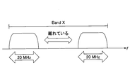
- Intra-band Non-continuous CA that bundles a plurality of discontinuous carriers in the same frequency band is applicable.
- Intra-band Non-contiguous CA as shown in the figure, carrier aggregation is performed using a plurality of carriers separated in the frequency band “BandX”.
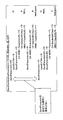
- combinations of carriers applicable to Intra-band Non-contiguous CA as shown in FIG. 2 are defined.
- CA — 41A-41C means that a carrier 41A of a bandwidth (BW) class A (20 MHz or the like) in a band 41 and a carrier 41C of a BW class C (40 MHz or the like) having a higher frequency than the carrier 41A are carriers. It shows that the combination can be aggregated.
- CA — 41C-41A indicates that the carrier 41C and the carrier 41A having a higher frequency than the carrier 41C are a combination capable of carrier aggregation.
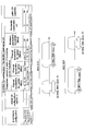
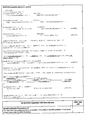
- the user apparatus In the LTE system, the user apparatus notifies the base station of capability information indicating the capability of the user apparatus.
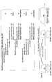
- the user apparatus In the current LTE standard (Non-Patent Document 2), the user apparatus notifies the combination of carriers that can be carrier-aggregated by capability information as shown in FIG. That is, according to the illustrated capability information, the user equipment supports carrier aggregation using two carriers of BW class A (41A) and BW class C (41C) of the band 41 for the downlink. In addition, it is shown that uplink communication is possible using a carrier corresponding to the carrier 41A.
- an object of the present invention is to provide a user apparatus that notifies a base station of a combination of carriers capable of carrier aggregation.
- an aspect of the present invention notifies the base station of capability information indicating a combination of a carrier capable of carrier aggregation together with a transmission / reception unit that transmits / receives a radio signal to / from the base station together with a bandwidth of each carrier.
- a capability information notification unit wherein the capability information notification unit includes a pair of combinations of all downlink carriers and uplink carriers that can be carrier-aggregated in the capability information.
- the present invention relates to a user device that notifies a combination.
- the user apparatus can notify the base station of a combination of carriers that can be carrier-aggregated.
- FIG. 1 is a schematic diagram showing an intra-band non-contiguous CA.
- FIG. 2 is a diagram showing a specific example of a band combination of Intra-band Non-contiguous CA.
- FIG. 3 is a diagram illustrating a signaling data structure of UE capability information for notifying a conventional CA band combination.
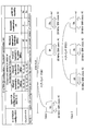
- FIG. 4 is a schematic diagram showing a specific example of a band combination of Intra-band Non-continuous CA.
- FIG. 5A is a schematic diagram illustrating a wireless communication system according to an embodiment of the present invention.
- FIG. 5B is a block diagram illustrating a hardware configuration of a user apparatus according to an embodiment of the present invention.
- FIG. 5C is a block diagram illustrating a hardware configuration of a base station according to an embodiment of the present invention.
- FIG. 6 is a block diagram illustrating a configuration of a user apparatus according to an embodiment of the present invention.
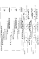
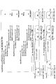
- FIG. 7 is a diagram illustrating a signaling data structure according to an embodiment of the present invention.
- FIG. 8 is a diagram illustrating a signaling data structure according to an embodiment of the present invention.
- FIG. 9 is a diagram illustrating a signaling data structure according to an embodiment of the present invention.
- FIG. 10 is a diagram illustrating a signaling data structure according to an embodiment of the present invention.
- FIG. 11 is a diagram illustrating a signaling data structure according to an embodiment of the present invention.
- FIG. 12 is a diagram illustrating a signaling data structure according to an embodiment of the present invention.
- FIG. 13A is a diagram illustrating a signaling data structure according to an embodiment of the present invention.
- FIG. 13B is a diagram illustrating a signaling data structure according to an embodiment of the present invention.
- FIG. 14 is a diagram illustrating a signaling data structure according to an embodiment of the present invention.
- FIG. 15 is a diagram illustrating a signaling data structure according to an embodiment of the present invention.
- FIG. 16 is a diagram illustrating a signaling data structure according to an embodiment of the present invention.
- FIG. 17 is a diagram illustrating a signaling data structure according to an embodiment of the present invention.
- FIG. 18 is a diagram illustrating a signaling data structure according to an embodiment of the present invention.
- FIG. 19 is a diagram illustrating a signaling data structure according to an embodiment of the present invention.
- FIG. 20 is a diagram illustrating a signaling data structure according to an embodiment of the present invention.
- FIG. 21 is a diagram illustrating a signaling data structure according to an embodiment of the present invention.
- FIG. 22 is a diagram illustrating a signaling data structure according to an embodiment of the present invention.
- FIG. 23 is a diagram illustrating a signaling data structure according to an embodiment of the present invention.
- FIG. 24 is a block diagram showing a hardware configuration according to an embodiment of the present invention.
- a user apparatus having a carrier aggregation function is disclosed.
- the user apparatus notifies the base station of the combination of carriers that can be carrier-aggregated in a certain frequency band in the capability information. For example, if the user equipment supports the pair band report omission function, the user equipment shall be able to report the combination of all downlink carrier / uplink carrier pairs capable of carrier aggregation individually. Only one pair combination is notified in the information.
- the base station determines that all the combinations of the pairs configured from the notified pair combinations can be carrier-aggregated. Can do.
- the order in which “BandParameters-r10” indicating two carriers is described is not meaningful, and the base station that has received the capability information is “41A-41C”. It cannot be determined which case “41C-41A” is supported by the user apparatus.
- the base station can use any downlink carrier as shown in FIG. It is not possible to determine whether the corresponding uplink carrier is supported. That is, as illustrated, two cases are assumed from one capability information, and the base station cannot determine which of these two cases is supported by the user apparatus. At this time, the capability information is described so that the frequency order of each carrier of the carrier combination can be specified. As a result, the base station that has received the capability information can specify the carrier configuration related to the frequency of each carrier as well as the combination of carriers that can be carrier-aggregated supported by the user apparatus, and perform appropriate carrier aggregation. It becomes possible to execute.
- FIG. 5A is a schematic diagram illustrating a wireless communication system according to an embodiment of the present invention.
- the wireless communication system 10 includes a user device 100 and a base station 200.
- the radio communication system 10 supports carrier aggregation in which the user apparatus 100 communicates using a primary cell (PCell) and a secondary cell (SCell) provided by the base station 200 at the same time.
- the radio communication system 10 is an LTE-Advanced system. There may be.
- the user apparatus 100 communicates with the base station 200 using two carriers CC # 1 and CC # 2. In the illustrated embodiment, only the base station 200 is shown, but in general, a large number of base stations are arranged to cover the service area of the wireless communication system 10.
- User apparatus 100 has a carrier aggregation function for communicating with base station 200 by simultaneously using a plurality of carriers provided by base station 200.
- the user apparatus 100 may be any appropriate information processing apparatus having a wireless communication function such as a smartphone, a mobile phone, a tablet, a mobile router, and a wearable terminal as illustrated.
- the user apparatus 100 transmits and receives radio signals to and from the base station 200, such as a CPU (Central Processing Unit) 101 such as a processor, a memory apparatus 102 such as a RAM (Random Access Memory) and flash memory, and the like.
- Wireless communication device 103, and user interface 104 such as an input / output device or a peripheral device.
- each function and process of the user device 100 described later may be realized by the CPU 101 processing or executing data or a program stored in the memory device 102.
- the user apparatus 100 is not limited to the hardware configuration described above, and may be configured by a circuit that realizes one or more of the processes described below.
- the base station 200 wirelessly connects to the user apparatus 100, thereby receiving, in the user apparatus 100, a downlink (DL) packet received from a network apparatus such as an upper station or a server that is communicatively connected to a core network (not shown). At the same time, the uplink (UL) packet received from the user apparatus 100 is transmitted to the network apparatus.
- the base station 200 is provided with two carriers CC # 1 and CC # 2, and has a carrier aggregation function for communicating using these carriers simultaneously.
- the base station 200 typically includes an antenna 201 for transmitting and receiving radio signals to and from the user apparatus 100, and a first communication interface (X2) for communicating with an adjacent base station. 202, a second communication interface (S1 interface, etc.) 203 for communicating with the core network, a processor 204 and a circuit for processing transmission / reception signals to / from the user device 100, and hardware resources such as a memory device 205. Is done.
- Each function and process of the base station 200 to be described later may be realized by the processor 204 processing or executing data or a program stored in the memory device 205.
- the base station 200 is not limited to the hardware configuration described above, and may have any other appropriate hardware configuration.
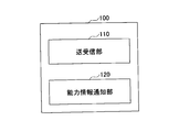
- FIG. 6 is a block diagram illustrating a configuration of the user apparatus 100 according to an embodiment of the present invention.
- the user device 100 includes a transmission / reception unit 110 and a capability information notification unit 120.
- the transmission / reception unit 110 transmits and receives radio signals to and from the base station 200. Specifically, in downlink communication, the transmission / reception unit 110 receives various downlink channels such as PDCCH (Physical Downlink Control Channel) and PDSCH (Physical Downlink Shared Channel) from the base station 200. On the other hand, in uplink communication, the transmission / reception unit 110 transmits various uplink channels such as PUCCH (Physical Uplink Control Channel) and PUSCH (Physical Uplink Shared Channel) to the base station 200. In addition, when carrier aggregation is set by the base station 200, the transmission / reception unit 110 communicates with the base station 200 by simultaneously using a plurality of set carriers.
- PDCCH Physical Downlink Control Channel
- PDSCH Physical Downlink Shared Channel
- the capability information notification unit 120 notifies the base station 200 of capability information indicating a combination of carriers that can be subjected to carrier aggregation together with the bandwidth of each carrier. At this time, the capability information notification unit 120 notifies capability information describing a combination of carriers that can be carrier-aggregated so as to specify the order of frequencies of the carriers.
- the user apparatus 100 is a combination of a BandX BW class A (20 MHz or the like) carrier (BandXA) and a BandX BW class C (40 MHz or the like) carrier (BandXC) having a higher frequency than the BandXA (BandXC). Assume that carrier aggregation is possible by BandXA-BandXC).
- the capability information notification unit 120 is not only capable of carrier aggregation by a combination of two carriers BandXA and BandXC, but also has a frequency that BandXA has a relatively low frequency and BandXC has a relatively high frequency.
- the base station 200 is notified of the capability information that specifies the order.
- the capability information notification unit 120 may list each carrier in the capability information in ascending order of frequency. That is, the capability information notification unit 120 may list each carrier in a carrier combination capable of carrier aggregation in the capability information in ascending order of the frequency of each carrier. That is, unlike the current LTE standard in which the order of listing carriers is not meaningful, the capability information according to the present embodiment is given meaning in the order of listing carriers.
- the user apparatus 100 can perform downlink carrier aggregation using a combination of BandXA and BandXC having a higher frequency than the BandXA (BandXA-BandXC), and uplink using a BandXA pair band. Assume that communication is possible.
- the capability information notification unit 120 corresponds to the BandXA for downlink having a relatively low frequency in “BandCombinationParameters-r10” for notifying the combination of carriers that support carrier aggregation.
- BandParameters-r10 indicating the uplink carrier to be performed is described at the upper level of the capability information
- “BandParameters-r10” indicating the BandXC for the downlink having a relatively high frequency is described at the lower level of the capability information.
- the base station 200 When receiving the capability information, the base station 200 has a relatively low frequency for BandXA described in the upper part of “BandCombinationParameters-r10” and a relatively high frequency for BandXC described in the lower part. Then, it can be recognized that communication with the user apparatus 100 is possible by the carrier configuration as shown in FIG.
- the user apparatus 100 can perform downlink carrier aggregation using a combination of BandXC and BandXA having a higher frequency than the BandXC (BandXC-BandXA). It is assumed that uplink communication is possible using a band.
- the capability information notification unit 120 describes “BandParameters-r10” indicating “BandCombinationParameters-r10”, which indicates a BandXC for a downlink having a relatively low frequency, in the upper part of the capability information. Then, “BandParameters-r10” indicating the downlink BandXA having a relatively high frequency and the corresponding uplink carrier is described below the capability information.
- the base station 200 When the capability information is received, the base station 200 has a relatively low frequency for BandXC described in the upper part of “BandCombinationParameters-r10” and a relatively high frequency for BandXA described in the lower part. Then, it can be recognized that the communication with the user apparatus 100 is possible by the carrier configuration as shown in FIG.
- the user apparatus 100 can perform downlink carrier aggregation using a combination of BandXA and BandXC having a higher frequency than the BandXA (BandXA-BandXC). It is assumed that uplink communication is possible using a band.
- the capability information notification unit 120 describes “BandParameters-r10” indicating “BandCombinationParameters-r10” indicating BandXA for downlink having a relatively low frequency in the upper part of the capability information. Then, “BandParameters-r10” indicating a downlink BandXC having a relatively high frequency and a corresponding uplink carrier is described below the capability information.
- the base station 200 When receiving the capability information, the base station 200 has a relatively low frequency for BandXA described in the upper part of “BandCombinationParameters-r10” and a relatively high frequency for BandXC described in the lower part. Then, it can be recognized that the communication with the user apparatus 100 is possible by the carrier configuration as shown in FIG.
- a BW class A carrier is used as an uplink carrier corresponding to BandXC (when “CA-BandwidthClass-r10” of “BandParametersUL-r10” is “A”), it is shown in FIG.
- Such two cases of carrier configurations are assumed. That is, a case where a relatively low frequency portion in an uplink carrier corresponding to BandXC is used for uplink communication (case C1) and a case where a relatively high frequency portion is used for uplink communication (case C2). Is assumed.
- the capability information notification unit 120 may indicate which partial band supports uplink communication.
- the capability information notification unit 120 may notify the uplink carrier corresponding to the downlink carrier or the partial band of the uplink carrier together with the combination of downlink carriers that can be carrier-aggregated. Thereby, the base station 200 can determine which of the carrier configurations of cases C1 and C2 is supported by the user apparatus 100.
- the user apparatus 100 can perform downlink carrier aggregation using a combination of BandXC and BandXA having a higher frequency than the BandXC (BandXC-BandXA). It is assumed that uplink communication is possible using a band.
- the capability information notification unit 120 in “BandCombinationParameters-r10”, indicates “BandParameters indicating a BandXC for a downlink having a relatively low frequency and a corresponding uplink carrier.
- -R10 is described in the upper part of the capability information
- BandParameters-r10 indicating the BandXA for the downlink having a relatively high frequency is described in the lower part of the capability information.
- the base station 200 When the capability information is received, the base station 200 has a relatively low frequency for BandXC described in the upper part of “BandCombinationParameters-r10” and a relatively high frequency for BandXA described in the lower part. Then, it can be recognized that the communication with the user apparatus 100 is possible by the carrier configuration as shown in FIG.
- a carrier of BW class A is used as an uplink carrier corresponding to BandXC (when “CA-BandwidthClass-r10” of “BandParametersUL-r10” is “A”), it is shown in FIG.
- Such two cases of carrier configurations are assumed. That is, a case where a relatively low frequency portion of an uplink carrier corresponding to BandXC is used for uplink communication (case D1) and a case where a relatively high frequency portion is used for uplink communication (case D2). Is assumed.
- the capability information notification unit 120 may indicate which partial band supports uplink communication.
- the capability information notification unit 120 may notify the uplink carrier corresponding to the downlink carrier or the partial band of the uplink carrier together with the combination of downlink carriers that can be carrier-aggregated. Thereby, the base station 200 can determine which of the carrier configurations of the cases D1 and D2 is supported by the user apparatus 100.
- the present invention is not limited to the two carriers described above, and is applicable to combinations of three or more carriers.
- the user apparatus 100 has a BandX BW class A carrier (BandXA), a BandX BW class C carrier (BandXC) having a higher frequency than the BandXA, and a BandX BW class A carrier having a higher frequency than the BandXC.
- BandXA BandX BW class A carrier
- BandXC BandX BW class C carrier
- BandXBW class A carrier having a higher frequency than the BandXC.
- carrier aggregation is possible by a combination (BandXA-BandXC-BandXA) with a carrier (BandXA).
- the capability information notification unit 120 is not only capable of carrier aggregation by a combination of these carriers BandXA and BandXC, but BandXA has the lowest frequency, BandXC has an intermediate frequency, and BandXA is the highest.
- the base station 200 may be notified of capability information specifying the frequency order of having frequencies.
- the present invention is not limited to this, and a plurality of carriers of the same BW class that can be carrier-aggregated are used.
- the present invention can be similarly applied to the embodiment in which the carrier is notified.
- the user apparatus 100 can perform downlink carrier aggregation using a combination of BandXA and BandXA having a higher frequency than the BandXA (BandXA-BandXA), and can perform a relatively low frequency BandXA. It is assumed that uplink communication is possible using a pair band.
- the capability information notification unit 120 in “BandCombinationParameters-r10”, the downlink BandXA having a relatively low frequency and the corresponding uplink carrier “BandParameters-r10” indicating “BandParameters-r10” indicating “BandParameters-r10” indicating downlink BandXA having a relatively high frequency is described below the capability information.
- the base station 200 describes the carrier for uplink in the upper “BandCombinationParameters-r10”. Therefore, the base station 200 communicates with the user apparatus 100 by the carrier configuration as shown in case E1 in FIG. It can be recognized that communication is possible.
- the user apparatus 100 can perform downlink carrier aggregation by a combination of BandXA and BandXA having a higher frequency than the BandXA (BandXA-BandXA), and has a relatively high frequency. It is assumed that uplink communication is possible by using the BandXA pair band.
- the capability information notification unit 120 uses “BandParameters-r10” indicating “BandCombinationParameters-r10” indicating a BandXA for a downlink having a relatively low frequency.
- BandParameters-r10 which describes the downlink BandXA having a relatively high frequency and the corresponding uplink carrier, is described below the capability information.
- the base station 200 When receiving the capability information, the base station 200 describes the carrier for uplink in the lower level “BandCombinationParameters-r10”, and therefore, the base station 200 and the user apparatus 100 with the carrier configuration as shown in case E2 of FIG. It can be recognized that communication is possible.
- FIG. 12 is a diagram illustrating a signaling data structure according to an embodiment of the present invention.
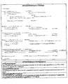
- the capability information notification unit 120 may notify the base station 200 of capability information as shown in FIG. According to the illustrated capability information, after the parameter “BandCombinationParameters-r10”, each carrier of the carrier combinations that can be carrier-aggregated is defined by the parameter “BandParameters-r10” in ascending order of frequency.
- the capability information notification unit 120 may specify the frequency order of each carrier according to the associated bandwidth. For example, when the user apparatus 100 supports “BandXA-BandXC”, the capability information notification unit 120 supports two carriers of BandXA and BandXC based on the existing capability information shown in FIG. And the order of the frequencies of these carriers may be indicated by the associated bandwidth (eg, ⁇ A, C ⁇ , etc.). Similarly, when the user apparatus 100 supports “BandXC-BandXA”, the capability information notification unit 120 supports two carriers of BandXA and BandXC based on the existing capability information illustrated in FIG. 3. And the order of the frequencies of these carriers may be indicated by the associated bandwidth (eg, ⁇ C, A ⁇ , etc.). Specifically, the capability information notification unit 120 notifies the order of the frequencies of the carriers in the carrier combination capable of carrier aggregation by adding the parameter “CA-BandwidthClass-r10” as shown in FIG. 13A. May be.
- the capability information notification unit 120 may notify that all the combinations of carriers indicated in the capability information can be carrier-aggregated.
- the user apparatus 100 supports all combinations of two carriers of BandXA and BandXC, that is, “BandXA-BandXA”, “BandXA-BandXC”, “BandXC-BandXA”, and “BandXC-BandXC”.
- the capability information notification unit 120 may set a parameter indicating that all the combinations of carriers indicated in the capability information can be carrier-aggregated, instead of notifying all combinations individually.
- the capability information notification unit 120 notifies that two carriers of BandXA and BandXC are supported by the existing capability information shown in FIG. 3, and parameters as shown in FIG. 13B. By setting “allCombinationSupported-r10” to “TRUE”, it may indicate that all combinations of these two carriers are supported.
- the capability information notification unit 120 may notify one carrier combination among all the carrier combinations that can be carrier-aggregated. That is, without using the parameters as described above with reference to FIG. 13B, the capability information notification unit 120 simply notifies the base station 200 of one carrier combination among all the carrier combinations that can be carrier-aggregated as capability information. May be.
- the user apparatus 100 supports all combinations of two carriers of BandXA and BandXC, that is, “BandXA-BandXA”, “BandXA-BandXC”, “BandXC-BandXA”, and “BandXC-BandXC”.
- the capability information notification unit 120 may notify the base station 200 of only one combination (such as “BandXA-BandXC”) as capability information instead of notifying all the combinations individually.
- the base station 200 Upon receiving the combination, the base station 200 receives all other combinations including the combination, that is, “BandXA-BandXA”, “BandXA-BandXC”, “BandXC-BandXA”, and “BandXC-BandXC” as carriers.
- Judge that aggregation is possible. In this embodiment, it is possible to notify that all the combinations configured by the combination can be carrier-aggregated by simply notifying one combination without using any special parameter.
- a report omission function that explicitly indicates that all other combinations configured from the combination can be carrier-aggregated may be set in the user apparatus 100.
- the capability information notification unit 120 indicates that the report omission function is set, and The base station 200 is notified of one combination among all the combinations that can be aggregated.
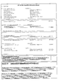
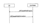
- the base station 200 transmits a capability information request “UECapabilityEnquiry” including a parameter “reduceIntraBandNonContComb” instructing execution of the report omitting function as illustrated in FIG. 14 to the user apparatus 100.
- UECapabilityEnquiry including a parameter “reduceIntraBandNonContComb” instructing execution of the report omitting function as illustrated in FIG. 14 to the user apparatus 100.
- the user apparatus 100 that supports the report omitting function may report only one combination of capability information “UE” instead of notifying all combinations that can be subjected to carrier aggregation. -Notification in “EUTRA-Capability”.
- the base station 200 can determine that all combinations that can be configured from the received combinations are capable of carrier aggregation.
- the user apparatus 100 that supports the report omission function has all combinations of two carriers of BandXA and BandXC, that is, “BandXA-BandXA”, “BandXA-BandXC”, “BandXC-BandXA”, and “BandXC-BandXC”. Suppose you support.
- the user apparatus 100 in addition to the notified “BandXA-BandXC”, the user apparatus 100 supports other combinations “BandXA-BandXA”, “BandXC-BandXA”, and “BandXC-BandXC”. Judgment can be made.
- the capability information notifying unit 120 when receiving the capability information request for instructing the execution of the report omitting function from the base station, notifying unit 120 notifies that the user apparatus 100 supports the report omitting function and uses one carrier. You may notify the combination of.
- the capability information notification unit 120 may notify a combination of one of the combinations of all downlink carriers and uplink carriers that can be carrier-aggregated in the capability information. Good.
- the downlink carrier and the uplink carrier are paired.
- a combination of BandXA (20 MHz, etc.) and BandXC (40 MHz, etc.) can be downlink carrier aggregated, and uplink communication using BandXA as a respective pair band of BandXA and BandXC for the downlink is possible.
- BandXA (20 MHz, etc.
- BandXC 40 MHz, etc.
- a combination of a pair of downlink BandXA and BandXC can be downlink carrier aggregated, and a pair combination that BandXA can perform uplink communication as a pair band of the BandXA for downlink ⁇ (DL: A, UL: A), (DL; C, UL: NULL) ⁇ and a combination of downlink BandXA and BandXC can be downlink carrier aggregation, and BandXA is an uplink as a pair band of the downlink BandXC.
- the capability information notification unit 120 may notify that the combination of the other pair is also possible by notifying the combination of one of these two pairs in the capability information. For example, the capability information notification unit 120 notifies the base station 200 of only ⁇ (DL: A, UL: A), (DL; C, UL: NULL) ⁇ , thereby ⁇ (DL: A, UL: NULL).
- the combination of pairs is a combination of carriers in the same frequency band.
- the uplink carrier corresponding to the BandXC has a relatively low frequency as in the embodiment shown in FIGS. A case where the portion is used for uplink communication and a case where a relatively high frequency portion is used for uplink communication are assumed.
- the uplink BandXA may be pairable with both frequency portions of the downlink BandXC.
- the present embodiment may be applied to a case where uplink communication is also possible for carrier aggregation.
- uplink communication is also possible for carrier aggregation.
- a combination of BandXC and BandXC can be downlink carrier aggregated and can be uplink carrier aggregated by BandXC (that is, two component carriers (CC)).
- CC component carriers
- the capability information notification unit 120 combines one pair ⁇ (DL: C, UL: C), (DL: C, UL: NULL), (DL: C, UL: NULL), (DL : C, UL: C) ⁇ to notify all other combinations of pairs ⁇ (DL: C, UL: C), (DL: C, UL: C), (DL: C, UL: NULL) ), (DL: C, UL: NULL) ⁇ , ⁇ (DL: C, UL: C), (DL: C, UL: NULL), (DL: C, UL: C), (DL: C, UL: (NULL) ⁇ , ⁇ (DL: C, UL: NULL), (DL: C, UL: C), (DL: C, UL: NULL), (DL: C, UL: C) ⁇ , ⁇ (DL: C, UL: NULL), (DL: C, UL: C), (DL: C, UL: NULL), (DL: C, UL: C) ⁇ , ⁇ (DL
- Band X is 4 CC CA ⁇ ⁇ (intra-band non-contiguous with two consecutive 2CCs apart) and uplink is 2 CA (2 consecutive CCs)
- Band X, DL: C UL Sending only Band: X, DL: C, UL: NULL
- Band X, DL: C, UL: C can be omitted if only: C, Band X, DL: C, UL: NULL are sent. .
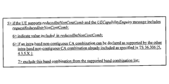
- the capability information notification unit 120 When receiving a capability information request for instructing execution of the pair band report omission function from the base station 200, the capability information notification unit 120 notifies that the user apparatus 100 supports the pair band report omission function, and You may notify the combination of one pair.
- the base station 200 transmits UECapabilityEnquiry as a capability information request to the user apparatus 100 having the pair band report omission function.
- the base station 200 may transmit UECapabilityEnquiry having a signaling structure as shown in FIG.
- the user apparatus 100 having the pair band report omission function can make one pair of combinations of all downlink carriers and uplink carriers capable of carrier aggregation.
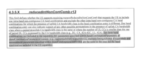
- the capability information notifying unit 120 sets reducedIntNonContComb to include in the capability information (UE-EUTRA-Capability) having a signaling structure as shown in FIG. 19 and includes all downlinks capable of carrier aggregation.
- the combination of one pair is notified from among the pair combinations of the carrier and the uplink carrier.
- the base station 200 can determine that all combinations of pairs that can be configured from the notified combination of pairs are possible.
- the communication function for one notified pair combination may be applied to the remaining pair combinations.
- the communication function may include one or more of a MIMO capability, a multiple timing advance capability, and a measurement gap capability.
- the capability information defines the MIMO capability, multiple timing advance capability, or measurement gap capability of the user apparatus 100 for one pair combination notified by the capability information notification unit 120 using the pair band report omission function. If so, the MIMO capability, multiple timing advance capability, or measurement gap capability defined for the one pair combination may be applied to the remaining pair combinations.
- the base station 200 recognizes that the same MIMO capability, multiple timing advance capability, or measurement gap capability can be applied to all other combinations of pairs configured from the notified combination of the one pair.
- the MIMO capability may indicate, for example, the number of layers that the user apparatus 100 can handle for the downlink, the uplink, or both the downlink and the uplink. That is, in the present embodiment, the downlink, uplink, or the number of layers of both downlink and uplink that can be supported by the user apparatus 100 for the notified one pair combination is applied to the remaining pair combinations.
- the MIMO capability may be notified by MIMO-CapabilityDL and MIMO-CapabilityUL in UE-EUTRA-Capability.
- the multiple timing advance (multiple TA) capability may indicate, for example, whether or not the user apparatus 100 supports multiple timing advance.
- the multiple timing advance is to control transmission timing according to a common TA value for one or more component carriers. That is, in the present embodiment, whether or not the multiple timing advance of the user apparatus 100 for the notified one pair combination is applied to the remaining pair combinations.
- the multiple timing advance capability may be notified by multipleTimingAdvance in UE-EUTRA-Capability.
- the measurement gap capability indicates whether a measurement gap is necessary for different frequency measurement or different RAT measurement. That is, in the present embodiment, the necessity of the measurement gap in the different frequency measurement or the different RAT measurement for the notified one pair combination is applied to the remaining pair combinations.
- the measurement gap capability may be notified by interFreq NeedForGaps or interRAT-NeedForGaps in UE-EUTRA-Capability.
- a reducedIntContComb as shown in FIG. 20 may be used. That is, according to the parameter, as described above, when one combination of a downlink carrier and an uplink carrier that can be carrier-aggregated is notified, all combinations of the pairs configured from the combination are notified. As shown in FIG. 21, the RF parameters (MIMO-CapabilityUL, multipleTimingAdvance, etc.) defined in the Band Combination Parameters or Band Combination Parameters Common for the notified combination of combinations are also available for the remaining pairs. May be applied. In this way, by notifying one combination of a downlink carrier and an uplink carrier capable of carrier aggregation and the MIMO capability and multiple timing advance capability regarding the combination of the pair, The MIMO capability and multiple timing advance capability associated with the combination can be notified.
- MIMO-CapabilityUL, multipleTimingAdvance, etc. defined in the Band Combination Parameters or Band Combination Parameters Common for the notified combination of combinations are also available for the remaining pairs.
- the necessity of a measurement gap defined in interFreq NeedForGaps or interRAT-NeedForGaps for the notified pair combination may be applied to the remaining pair combinations.
- it is related to the remaining pair combinations by notifying one combination of downlink carrier and uplink carrier pairs capable of carrier aggregation and the measurement gap capability for the pair combination. Notification of measurement gap ability.
- the communication function to which the pair band report omission function is applied is not limited to the above-described MIMO capability, multiple timing advance capability, and measurement gap capability.
- MIMO Multiple Assisted Cancellation / Suppression
- D2D Device to Device
- simultaneous communication capability CommSupportedBandsPerBC shown in FIG. 23.
- CDMA Code Division Multiple Access 2000
- UMB Ultra Mobile Broadband
- IEEE 802. .11 Wi-Fi
- WiMAX IEEE 802.16
- UWB Ultra-Wideband
- R Bluetooth
- the information and signals described above may be represented using any of a variety of different technologies and techniques.
- data, commands, commands, information, signals, bits, symbols and chips referred to throughout the above description may be voltages, currents, electromagnetic waves, magnetic fields or magnetic particles, light fields or photons, or any combination thereof.
- the software or instructions can also be transmitted over a transmission medium.
- a transmission medium For example, when the software is transmitted from a website, server or other remote source using coaxial cable, fiber optic cable, twisted pair, digital subscriber line (DSL), or wireless technologies such as infrared, radio and microwave Coaxial cable, fiber optic cable, twisted pair, digital subscriber line (DSL), or wireless technologies such as infrared, radio and microwave are included within the definition of transmission media.
- the block diagram used in the description of the above embodiment shows functional unit blocks. These functional blocks (components) are realized by any combination of hardware and / or software. Further, the means for realizing each functional block is not particularly limited.
- each functional block may be realized by one device physically and / or logically coupled, and two or more devices physically and / or logically separated may be directly and / or indirectly. (For example, wired and / or wireless) and may be realized by these plural devices.
- the user apparatus 100 and the base stations 201 and 202 in an embodiment of the present invention may function as a computer that performs processing of the wireless communication method of the present invention.
- FIG. 24 is a block diagram illustrating a hardware configuration of the user apparatus 100 and the base station 200 according to an embodiment of the present invention.
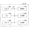
- the above-described user apparatus 100 and base station 200 may be physically configured as a computer apparatus including a processor 1001, a memory 1002, a storage 1003, a communication apparatus 1004, an input apparatus 1005, an output apparatus 1006, a bus 1007, and the like. .
- the term “apparatus” can be read as a circuit, a device, a unit, or the like.
- the hardware configurations of the user apparatus 100 and the base station 200 may be configured to include one or a plurality of the apparatuses illustrated in the figure, or may be configured not to include some apparatuses.
- Each function in the user apparatus 100 and the base station 200 is obtained by reading predetermined software (program) on hardware such as the processor 1001 and the memory 1002, so that the processor 1001 performs an operation, and communication by the communication apparatus 1004 or memory This is realized by controlling data reading and / or writing in the storage 1003 and the storage 1003.
- the processor 1001 controls the entire computer by operating an operating system, for example.
- the processor 1001 may be configured by a central processing unit (CPU) including an interface with peripheral devices, a control device, an arithmetic device, a register, and the like.
- CPU central processing unit
- each component described above may be realized by the processor 1001.
- the processor 1001 reads programs (program codes), software modules, and data from the storage 1003 and / or the communication device 1004 to the memory 1002, and executes various processes according to these.
- programs program codes
- software modules software modules
- data data from the storage 1003 and / or the communication device 1004 to the memory 1002, and executes various processes according to these.
- the program a program that causes a computer to execute at least a part of the operations described in the above embodiments is used.
- the processing by each component of the user apparatus 100 and the base station 200 may be realized by a control program stored in the memory 1002 and operated by the processor 1001, or may be realized similarly for other functional blocks.
- the above-described various processes have been described as being executed by one processor 1001, they may be executed simultaneously or sequentially by two or more processors 1001.
- the processor 1001 may be implemented by one or more chips.
- the program may be transmitted from a network via a telecommunication line.
- the memory 1002 is a computer-readable recording medium, and includes, for example, at least one of ROM (Read Only Memory), EPROM (Erasable Programmable ROM), EEPROM (Electrically Erasable Programmable ROM), RAM (Random Access Memory), and the like. May be.
- the memory 1002 may be called a register, a cache, a main memory (main storage device), or the like.
- the memory 1002 can store a program (program code), a software module, and the like that can be executed to implement the wireless communication method according to the embodiment of the present invention.
- the storage 1003 is a computer-readable recording medium such as an optical disk such as a CD-ROM (Compact Disc ROM), a hard disk drive, a flexible disk, a magneto-optical disk (for example, a compact disk, a digital versatile disk, a Blu-ray). (Registered trademark) disk, smart card, flash memory (for example, card, stick, key drive), floppy (registered trademark) disk, magnetic strip, and the like.
- the storage 1003 may be referred to as an auxiliary storage device.
- the storage medium described above may be, for example, a database, server, or other suitable medium including the memory 1002 and / or the storage 1003.
- the communication device 1004 is hardware (transmission / reception device) for performing communication between computers via a wired and / or wireless network, and is also referred to as a network device, a network controller, a network card, a communication module, or the like.
- a network device for performing communication between computers via a wired and / or wireless network
- a network controller for controlling network access
- a network card for controlling communication between computers via a wired and / or wireless network
- a communication module or the like.
- each of the above-described components may be realized by the communication device 1004.
- the input device 1005 is an input device (for example, a keyboard, a mouse, a microphone, a switch, a button, a sensor, etc.) that accepts an input from the outside.
- the output device 1006 is an output device (for example, a display, a speaker, an LED lamp, etc.) that performs output to the outside.
- the input device 1005 and the output device 1006 may have an integrated configuration (for example, a touch panel).
- each device such as the processor 1001 and the memory 1002 is connected by a bus 1007 for communicating information.
- the bus 1007 may be configured with a single bus or may be configured with different buses between apparatuses.
- the user apparatus 100 and the base station 200 include hardware such as a microprocessor, a digital signal processor (DSP), an ASIC (Application Specific Integrated Circuit), a PLD (Programmable Logic Device), and an FPGA (Field Programmable Gate Array). Hardware may be configured, and a part or all of each functional block may be realized by the hardware.
- the processor 1001 may be implemented by at least one of these hardware.
- notification of information is not limited to the aspect / embodiment described in this specification, and may be performed by other methods.
- notification of information includes physical layer signaling (for example, DCI (Downlink Control Information), UCI (Uplink Control Information)), upper layer signaling (for example, RRC (Radio Resource Control) signaling, MAC (Medium Access Control) signaling), It may be implemented by broadcast information (MIB (Master Information Block), SIB (System Information Block)), other signals, or a combination thereof.
- the RRC signaling may be referred to as an RRC message, and may be, for example, an RRC connection setup (RRC Connection Setup) message, an RRC connection reconfiguration (RRC Connection Reconfiguration) message, or the like.
- Each aspect / example described in this specification includes LTE (Long Term Evolution), LTE-A (LTE-Advanced), SUPER 3G, IMT-Advanced, 4G, 5G, FRA (Future Radio Access), W-CDMA.
- LTE Long Term Evolution
- LTE-A Long Term Evolution-Advanced
- SUPER 3G IMT-Advanced
- 4G 5G
- FRA Full Radio Access
- W-CDMA Wideband
- GSM registered trademark
- CDMA2000 Code Division Multiple Access 2000
- UMB User Mobile Broadband
- IEEE 802.11 Wi-Fi
- IEEE 802.16 WiMAX
- IEEE 802.20 UWB (Ultra-WideBand
- the present invention may be applied to a Bluetooth (registered trademark), a system using another appropriate system, and / or a next generation system extended based on the system.
- the specific operation performed by the base station 200 in this specification may be performed by the upper node in some cases.
- various operations performed for communication with a terminal may be performed by the base station and / or other network nodes other than the base station (for example, Obviously, this can be done by MME or S-GW, but not limited to these.
- MME Mobility Management Entity
- S-GW Packet Control Function
- Information etc. can be output from the upper layer (or lower layer) to the lower layer (or upper layer). Input / output may be performed via a plurality of network nodes.
- the input / output information or the like may be stored in a specific location (for example, a memory) or may be managed by a management table. Input / output information and the like can be overwritten, updated, or additionally written. The output information or the like may be deleted. The input information or the like may be transmitted to another device.
- the determination may be performed by a value represented by 1 bit (0 or 1), may be performed by a true / false value (Boolean: true or false), or may be performed by comparing numerical values (for example, a predetermined value) Comparison with the value).
- notification of predetermined information is not limited to explicitly performed, but is performed implicitly (for example, notification of the predetermined information is not performed). Also good.
- software, instructions, etc. may be transmitted / received via a transmission medium.
- software may use websites, servers, or other devices using wired technology such as coaxial cable, fiber optic cable, twisted pair and digital subscriber line (DSL) and / or wireless technology such as infrared, wireless and microwave.
- wired technology such as coaxial cable, fiber optic cable, twisted pair and digital subscriber line (DSL) and / or wireless technology such as infrared, wireless and microwave.
- DSL digital subscriber line
- wireless technology such as infrared, wireless and microwave.
- the channel and / or symbol may be a signal.
- the signal may be a message.
- the component carrier (CC) may be called a carrier frequency, a cell, or the like.
- system and “network” used in this specification are used interchangeably.
- information, parameters, and the like described in this specification may be represented by absolute values, may be represented by relative values from a predetermined value, or may be represented by other corresponding information.
- the radio resource may be indicated by an index.
- the base station can accommodate one or a plurality of (for example, three) cells (also called sectors). When the base station accommodates a plurality of cells, the entire coverage area of the base station can be divided into a plurality of smaller areas, and each smaller area can be divided into a base station subsystem (for example, an indoor small base station RRH: Remote).
- a communication service can also be provided by Radio Head).
- the term “cell” or “sector” refers to part or all of the coverage area of a base station and / or base station subsystem that provides communication services in this coverage. Further, the terms “base station”, “eNB”, “cell”, and “sector” may be used interchangeably herein.
- a base station may also be called in terms such as a fixed station (fixed station), a NodeB, an eNodeB (eNB), an access point (access point), a femto cell, and a small cell.
- a mobile station is defined by those skilled in the art as a subscriber station, mobile unit, subscriber unit, wireless unit, remote unit, mobile device, wireless device, wireless communication device, remote device, mobile subscriber station, access terminal, mobile terminal, wireless It may also be called terminal, remote terminal, handset, user agent, mobile client, client, or some other appropriate terminology.
- determining may encompass a wide variety of actions.
- “Judgment”, “decision” can be, for example, calculating, computing, processing, deriving, investigating, looking up (eg, table, database or another (Searching in the data structure), and confirming (ascertaining) what has been confirmed may be considered as “determining” or “determining”.
- “determination” and “determination” include receiving (for example, receiving information), transmitting (for example, transmitting information), input (input), output (output), and access. (accessing) (e.g., accessing data in a memory) may be considered as “determined” or "determined”.
- determination and “decision” means that “resolving”, “selecting”, “choosing”, “establishing”, and “comparing” are regarded as “determining” and “deciding”. May be included. In other words, “determination” and “determination” may include considering some operation as “determination” and “determination”.
- connection means any direct or indirect connection or coupling between two or more elements and It can include the presence of one or more intermediate elements between two “connected” or “coupled” elements.
- the coupling or connection between the elements may be physical, logical, or a combination thereof.
- the two elements are radio frequency by using one or more wires, cables and / or printed electrical connections, and as some non-limiting and non-inclusive examples
- electromagnetic energy such as electromagnetic energy having a wavelength in the region, microwave region, and light (both visible and invisible) region, it can be considered to be “connected” or “coupled” to each other.
- the reference signal may be abbreviated as RS (Reference Signal), and may be referred to as a pilot depending on an applied standard.
- RS Reference Signal
- the phrase “based on” does not mean “based only on”, unless expressly specified otherwise. In other words, the phrase “based on” means both “based only on” and “based at least on.”
- any reference to elements using designations such as “first”, “second”, etc. as used herein does not generally limit the amount or order of those elements. These designations can be used herein as a convenient way to distinguish between two or more elements. Thus, a reference to the first and second elements does not mean that only two elements can be employed there, or that in some way the first element must precede the second element.
- the radio frame may be composed of one or a plurality of frames in the time domain. Each frame or frames in the time domain may be referred to as a subframe. A subframe may further be composed of one or more slots in the time domain. A slot may further be composed of one or more symbols (OFDM symbols, SC-FDMA symbols, etc.) in the time domain. Each of the radio frame, subframe, slot, and symbol represents a time unit for transmitting a signal. Radio frames, subframes, slots, and symbols may be called differently corresponding to each. For example, in the LTE system, the base station performs scheduling for allocating radio resources (frequency bandwidth, transmission power, etc. that can be used in each mobile station) to each mobile station.
- radio resources frequency bandwidth, transmission power, etc. that can be used in each mobile station
- TTI Transmission Time Interval
- one subframe may be called a TTI
- a plurality of consecutive subframes may be called a TTI
- one slot may be called a TTI.
- a resource block is a resource allocation unit in the time domain and the frequency domain, and may include one or a plurality of continuous subcarriers in the frequency domain.
- one or a plurality of symbols may be included, and one slot, one subframe, or a length of 1 TTI may be included.
- One TTI and one subframe may each be composed of one or a plurality of resource blocks.
- the structure of the radio frame described above is merely an example, and the number of subframes included in the radio frame, the number of slots included in the subframe, the number of symbols and resource blocks included in the slots, and the subframes included in the resource block
- the number of carriers can be variously changed.
Landscapes
- Engineering & Computer Science (AREA)
- Computer Networks & Wireless Communication (AREA)
- Signal Processing (AREA)
- Databases & Information Systems (AREA)
- Mobile Radio Communication Systems (AREA)
Abstract
L'invention concerne un dispositif d'utilisateur qui signale, à une station de base, une combinaison de porteuses permettant une agrégation de porteuses. Un aspect de la présente invention se rapporte à un dispositif d'utilisateur qui comprend une unité d'émission/réception en vue d'émettre et de recevoir un signal sans fil vers et depuis une station de base, et une unité de rapport d'informations de capacité permettant de rapporter, à la station de base, des informations de capacité indiquant, conjointement avec la largeur de bande de chaque porteuse, une combinaison de porteuses permettant une agrégation de porteuses, l'unité de rapport d'informations de capacité rapportant une combinaison de paires parmi l'ensemble des combinaisons de paire de porteuses de liaison descendante et de porteuses de liaison montante dans les informations de capacité qui permettent une agrégation de porteuses.
Applications Claiming Priority (4)
| Application Number | Priority Date | Filing Date | Title |
|---|---|---|---|
| JP2016029568 | 2016-02-19 | ||
| JP2016-029568 | 2016-02-19 | ||
| JP2016-033316 | 2016-02-24 | ||
| JP2016033316A JP2017152911A (ja) | 2016-02-19 | 2016-02-24 | ユーザ装置 |
Publications (1)
| Publication Number | Publication Date |
|---|---|
| WO2017141571A1 true WO2017141571A1 (fr) | 2017-08-24 |
Family
ID=59625849
Family Applications (1)
| Application Number | Title | Priority Date | Filing Date |
|---|---|---|---|
| PCT/JP2017/000461 WO2017141571A1 (fr) | 2016-02-19 | 2017-01-10 | Dispositif d'utilisateur |
Country Status (1)
| Country | Link |
|---|---|
| WO (1) | WO2017141571A1 (fr) |
Cited By (5)
| Publication number | Priority date | Publication date | Assignee | Title |
|---|---|---|---|---|
| CN112740785A (zh) * | 2018-09-27 | 2021-04-30 | 株式会社Ntt都科摩 | 用户装置 |
| CN113424619A (zh) * | 2019-02-14 | 2021-09-21 | 株式会社Ntt都科摩 | 用户装置 |
| CN113455072A (zh) * | 2019-02-25 | 2021-09-28 | 株式会社Ntt都科摩 | 用户装置以及通信方法 |
| CN113455070A (zh) * | 2019-02-21 | 2021-09-28 | 株式会社Ntt都科摩 | 用户装置以及基站装置 |
| CN113491161A (zh) * | 2019-02-25 | 2021-10-08 | 株式会社Ntt都科摩 | 用户装置以及通信方法 |
-
2017
- 2017-01-10 WO PCT/JP2017/000461 patent/WO2017141571A1/fr active Application Filing
Non-Patent Citations (2)
| Title |
|---|
| "Continuing discussion on intra-band non-contiguous CA capability", 3GPP TSG-RAN WG2 #93 R2-161620, 3GPP, 6 February 2016 (2016-02-06), pages 1, 2, XP051055450 * |
| "Modification of network requested CA band combination retrieval for intra-band non-contiguous CA", 3GPP TSG-RAN WG2 MEETING #93 R2-161625, 3GPP, 6 February 2016 (2016-02-06), pages 3, 18, 20, XP051054983 * |
Cited By (8)
| Publication number | Priority date | Publication date | Assignee | Title |
|---|---|---|---|---|
| CN112740785A (zh) * | 2018-09-27 | 2021-04-30 | 株式会社Ntt都科摩 | 用户装置 |
| CN113424619A (zh) * | 2019-02-14 | 2021-09-21 | 株式会社Ntt都科摩 | 用户装置 |
| CN113424619B (zh) * | 2019-02-14 | 2024-05-07 | 株式会社Ntt都科摩 | 用户装置 |
| CN113455070A (zh) * | 2019-02-21 | 2021-09-28 | 株式会社Ntt都科摩 | 用户装置以及基站装置 |
| CN113455070B (zh) * | 2019-02-21 | 2024-05-03 | 株式会社Ntt都科摩 | 用户装置以及基站装置 |
| CN113455072A (zh) * | 2019-02-25 | 2021-09-28 | 株式会社Ntt都科摩 | 用户装置以及通信方法 |
| CN113491161A (zh) * | 2019-02-25 | 2021-10-08 | 株式会社Ntt都科摩 | 用户装置以及通信方法 |
| CN113491161B (zh) * | 2019-02-25 | 2023-07-28 | 株式会社Ntt都科摩 | 用户装置以及通信方法 |
Similar Documents
| Publication | Publication Date | Title |
|---|---|---|
| WO2017195471A1 (fr) | Dispositif utilisateur et station de base | |
| JP7111721B2 (ja) | 端末、無線通信方法、基地局及びシステム | |
| WO2017057439A1 (fr) | Dispositif d'utilisateur et procédé pour rapporter des informations de capacité | |
| WO2018230361A1 (fr) | Dispositif utilisateur | |
| WO2017170223A1 (fr) | Dispositif d'utilisateur | |
| WO2017141571A1 (fr) | Dispositif d'utilisateur | |
| WO2017213223A1 (fr) | Terminal d'utilisateur, station de base radio, et procédé de radiocommunication | |
| US11716696B2 (en) | User equipment and base station | |
| WO2017170117A1 (fr) | Dispositif d'utilisateur | |
| US11770697B2 (en) | Terminal, transmission method, and radio communication system | |
| JPWO2019030870A1 (ja) | ユーザ端末及び無線通信方法 | |
| WO2018083867A1 (fr) | Station de base et dispositif utilisateur | |
| WO2020115908A1 (fr) | Terminal et procédé de communication | |
| WO2018142990A1 (fr) | Station de base et dispositif utilisateur | |
| WO2018052017A1 (fr) | Terminal d'utilisateur, et procédé de communication sans fil | |
| JPWO2019064604A1 (ja) | 基地局及びユーザ装置 | |
| JP2019036873A (ja) | 基地局 | |
| CN111165043B (zh) | 基站以及状态控制方法 | |
| WO2017183245A1 (fr) | Équipement utilisateur | |
| JP2019036874A (ja) | 基地局 | |
| WO2022039189A1 (fr) | Terminal et système de communication sans fil | |
| US11916636B2 (en) | Terminal and communication method | |
| US20220159738A1 (en) | User equipment and base station apparatus | |
| WO2019180849A1 (fr) | Station de base | |
| US20230014196A1 (en) | Base station and radio communication method |
Legal Events
| Date | Code | Title | Description |
|---|---|---|---|
| 121 | Ep: the epo has been informed by wipo that ep was designated in this application |
Ref document number: 17752835 Country of ref document: EP Kind code of ref document: A1 |
|
| NENP | Non-entry into the national phase |
Ref country code: DE |
|
| 122 | Ep: pct application non-entry in european phase |
Ref document number: 17752835 Country of ref document: EP Kind code of ref document: A1 |