EP3337001B1 - System and method for discharging a defective battery cell - Google Patents
System and method for discharging a defective battery cell Download PDFInfo
- Publication number
- EP3337001B1 EP3337001B1 EP16203922.6A EP16203922A EP3337001B1 EP 3337001 B1 EP3337001 B1 EP 3337001B1 EP 16203922 A EP16203922 A EP 16203922A EP 3337001 B1 EP3337001 B1 EP 3337001B1
- Authority
- EP
- European Patent Office
- Prior art keywords
- battery cell
- power switching
- dedicated
- defective
- short circuit
- Prior art date
- Legal status (The legal status is an assumption and is not a legal conclusion. Google has not performed a legal analysis and makes no representation as to the accuracy of the status listed.)
- Not-in-force
Links
Images
Classifications
-
- H—ELECTRICITY
- H02—GENERATION; CONVERSION OR DISTRIBUTION OF ELECTRIC POWER
- H02J—ELECTRIC POWER NETWORKS; CIRCUIT ARRANGEMENTS OR SYSTEMS FOR SUPPLYING OR DISTRIBUTING ELECTRIC POWER; SYSTEMS FOR STORING ELECTRIC ENERGY
- H02J7/00—Circuit arrangements for charging or discharging batteries or for supplying loads from batteries
- H02J7/50—Circuit arrangements for charging or discharging batteries or for supplying loads from batteries acting upon multiple batteries simultaneously or sequentially
- H02J7/52—Circuit arrangements for charging or discharging batteries or for supplying loads from batteries acting upon multiple batteries simultaneously or sequentially for charge balancing, e.g. equalisation of charge between batteries
- H02J7/56—Active balancing, e.g. using capacitor-based, inductor-based or DC-DC converters
-
- H—ELECTRICITY
- H01—ELECTRIC ELEMENTS
- H01M—PROCESSES OR MEANS, e.g. BATTERIES, FOR THE DIRECT CONVERSION OF CHEMICAL ENERGY INTO ELECTRICAL ENERGY
- H01M10/00—Secondary cells; Manufacture thereof
- H01M10/42—Methods or arrangements for servicing or maintenance of secondary cells or secondary half-cells
- H01M10/4207—Methods or arrangements for servicing or maintenance of secondary cells or secondary half-cells for several batteries or cells simultaneously or sequentially
-
- H—ELECTRICITY
- H01—ELECTRIC ELEMENTS
- H01M—PROCESSES OR MEANS, e.g. BATTERIES, FOR THE DIRECT CONVERSION OF CHEMICAL ENERGY INTO ELECTRICAL ENERGY
- H01M10/00—Secondary cells; Manufacture thereof
- H01M10/42—Methods or arrangements for servicing or maintenance of secondary cells or secondary half-cells
- H01M10/44—Methods for charging or discharging
- H01M10/441—Methods for charging or discharging for several batteries or cells simultaneously or sequentially
-
- H—ELECTRICITY
- H02—GENERATION; CONVERSION OR DISTRIBUTION OF ELECTRIC POWER
- H02J—ELECTRIC POWER NETWORKS; CIRCUIT ARRANGEMENTS OR SYSTEMS FOR SUPPLYING OR DISTRIBUTING ELECTRIC POWER; SYSTEMS FOR STORING ELECTRIC ENERGY
- H02J7/00—Circuit arrangements for charging or discharging batteries or for supplying loads from batteries
- H02J7/60—Circuit arrangements for charging or discharging batteries or for supplying loads from batteries including safety or protection arrangements
-
- Y—GENERAL TAGGING OF NEW TECHNOLOGICAL DEVELOPMENTS; GENERAL TAGGING OF CROSS-SECTIONAL TECHNOLOGIES SPANNING OVER SEVERAL SECTIONS OF THE IPC; TECHNICAL SUBJECTS COVERED BY FORMER USPC CROSS-REFERENCE ART COLLECTIONS [XRACs] AND DIGESTS
- Y02—TECHNOLOGIES OR APPLICATIONS FOR MITIGATION OR ADAPTATION AGAINST CLIMATE CHANGE
- Y02E—REDUCTION OF GREENHOUSE GAS [GHG] EMISSIONS, RELATED TO ENERGY GENERATION, TRANSMISSION OR DISTRIBUTION
- Y02E60/00—Enabling technologies; Technologies with a potential or indirect contribution to GHG emissions mitigation
- Y02E60/10—Energy storage using batteries
Definitions
- the present invention relates to a system for discharging a defective battery cell and to a corresponding method for discharging a defective battery cell.
- WO2015/149136 A1 discloses a system for discharging a defective battery cell having an internal short circuit of a rechargeable battery unit having at least two battery cells connected in series, comprising a balancing circuit for balancing system for said battery cells, a control unit for controlling said balancing circuit, at least one sensor unit for detecting if a short circuit exists in at least one of the battery cells, wherein the control unit is capable of controlling the balancing circuit such that, after detection that a short circuit does exist in a battery cell, charge of this defective battery cell is transferred.
- balancing circuits which aim to transfer charge from one cell to the other cells in a series connected arrangement to recover energy stored in the cells when performing balancing of the cells.
- US 2014/042936 A1 discloses a balancing circuit for discharging cells in case of a short circuit in one of the cells.
- the invention relates to a method for discharging a defective battery cell having an internal short circuit of a rechargeable battery unit having at least two battery cells connected in series and a balancing circuit for balancing said battery cells.
- rechargeable battery cells such as lithium ion cells
- battery cells are installed in electric vehicles and hybrid electric vehicles to supply electric drive units of such vehicles with electric power.
- battery cells are combined to form a battery unit with battery cells being connected in series.
- the battery unit can be a rechargeable battery or a battery module for composing a modularly constructed rechargeable battery.
- a short circuit may occur inside of a defective battery cell. Then, a large short circuit current flows inside of the defective battery cell generating heat causing overheating of the defective battery cell. This overheating may lead to a decomposition reaction of electrolyte and electrode inside of the defective battery cell generating gas inside of the defective battery cell. Then, a pressure inside of the defective battery cell increases due to the gas generation. This event is referred to as thermal runaway of a defective battery cell. A thermal runaway of one defective battery cell of a rechargeable battery unit with several battery cells may lead to a thermal runaway of further battery cells of the rechargeable battery unit.
- a battery cell may comprise a venting device for venting the battery cell and thereby reducing the pressure in the battery cell.
- a thermal runaway of a defective battery cell may also cause an ignition of cell components of the defective battery cell.
- BMS battery management system
- a system according to the present invention for discharging a defective battery cell having an internal short circuit of a rechargeable battery unit having at least two battery cells connected in series is defined in independent claim 1.
- a defective battery cell having a defect in the form of an internal short circuit of a rechargeable battery unit is discharged using the balancing circuit of the rechargeable battery unit.
- the system according to the invention comprises the control unit which controls the balancing circuit. No additional discharge load is necessary to discharge the defective battery cell.
- charge of the defective battery cell which for example may have a slowly developing internal short circuit, can be transferred successively to the other battery cells of the rechargeable battery unit. Through this the energy of the defective battery cell is reduced so that thermal runaway and venting of the defective battery cell and ignition of battery cell components are reliably prevented.
- the balancing circuit of the system according to the invention is used for balancing the battery cells of the rechargeable battery unit, i.e. for drawing energy from the most charged battery cell or cells of the rechargeable battery unit and transferring the drawn energy to the least charged battery cell or cells.
- the battery cells of the rechargeable battery unit may have a similar or identical state of charge (SOC).
- the balancing circuit typically comprises at least one power switching converter for each battery cell. These power switching converters are also switched for discharging a defective battery cell of the rechargeable battery unit.
- Each power switching converter may comprise a switching device, a diode and at least one inductor.
- the switching device can be a field-effect transistor (FET), bipolar transistor or the like.
- FET field-effect transistor
- the charge of the defective battery cell is successively transferred to other battery cells by means of the balancing circuit. This means that the charge of the defective cell is transferred in specific amounts from the defective battery cell to at least one battery cell directly adjacent to the defective battery cell, and from this adjacent battery cell to the next battery cell, and so on.
- the control unit for controlling said balancing circuit may be a separate unit or may be implemented in a battery management system (BMS) of the rechargeable battery unit.
- BMS battery management system
- the control unit controls the power switching converters of the balancing circuit to discharge a defective battery cell.
- the sensor unit for detecting, if a short circuit exists in at least one of the battery cells may be a voltage sensor, a current sensor, a temperature sensor or the like.
- the sensor unit is connected to the control unit to provide sensor signals to the control circuit that are indicative of a short circuit a battery cell.
- the sensor unit may comprise for each battery cell a separate cell sensor.
- the balancing circuit comprises at least two power switching converters each being dedicated to one of the battery cells and sharing at least one inductor, and at least two diodes each being dedicated to one of the battery cells and each allowing a charge current to flow through the respective battery cell, and the control unit is configured to control the balancing circuit such that, after detection that a short circuit does exist in a battery cell, charge of this defective battery cell is transferred to the battery cell whose dedicated power switching converter shares the inductor with the power switching converter being dedicated to the defective battery cell.
- a field-effect transistor of the power switching converter being dedicated to the defective battery cell is turned on for a specific period, and a field-effect transistor of the power switching converter sharing the inductor with the power switching converter being dedicated to the defective battery cell is kept turned off.
- a specific amount of energy is first stored in the inductor.
- the inductor releases its stored energy so that a current flows through the diode being dedicated to the functional adjacent battery cell and through this battery cell.
- this battery cell is charged.
- This procedure can be repeated to discharge the defective battery cell.
- the charge added to the functional battery cell can be transferred from this battery cell to the other battery cells in the same manner. Through this, the charge of the defective battery cell can be distributed over the functional battery cells of the rechargeable battery unit.
- control unit is configured to control the balancing circuit such that, after detection that a short circuit does exist in a battery cell, the power switching converter being dedicated to this defective cell is operated with a changed switching duty being different from a switching duty provided when no internal short circuit is detected, and that the power switching converter sharing the inductor with the power switching converter being dedicated to the defective battery cell is kept switched off.
- This operation may be performed as long as the state of charge (SOC) of the respective functional adjacent battery cell does not exceed a predefined threshold.
- the balancing circuit comprises at least two power switching converters each being dedicated to one of the battery cells and being inductively coupled with each other, and the control unit is configured to control the balancing circuit such that, after detection that a short circuit does exist in a battery cell, charge of this defective battery cell is transferred to the battery cell whose dedicated power switching converter is inductively coupled with the power switching converter being dedicated to the defective battery cell. If a short in a defective battery cell is detected, a field-effect transistor of the power switching converter being dedicated to the defective battery cell is turned on for a specific period, and a field-effect transistor of the power switching converter inductively coupled with the power switching converter being dedicated to the defective battery cell is kept turned off.
- control unit is configured to control the balancing circuit such that, after detection that a short circuit does exist in a battery cell, a switching frequency of the power switching converter being dedicated to this defective battery cell is constant or varied over a discharge period.
- the switching frequency of the power switching converter being dedicated to the defective cell can be adapted to the specific case.
- control unit is configured to control the balancing circuit such that the power switching converters are not switched at the same time. This feature is important for an optimal transfer of charge from the defective battery cell to the other battery cells.
- a method according to the present invention for discharging a defective battery cell having an internal short circuit of a rechargeable battery unit having at least two battery cells connected in series and a balancing circuit for balancing said battery cells, is defined in independent claim 4.
- charge of the defective battery cell is transferred from the defective battery cell via a power switching converter being dedicated to the defective battery cell and via a power switching converter being dedicated to another battery cell to the other battery cell by means of an inductor being shared by the power switching converters or by means of an inductive coupling of the power switching converters.
- the power switching converter being dedicated to this defective battery cell is operated with a changed switching duty being different from a switching duty provided when no internal short circuit is detected, and the power switching converter sharing the inductor with the power switching converter being dedicated to the defective battery cell or inductively coupled with the power switching converter being dedicated to the defective battery cell is kept switched off.
- a switching frequency of the power switching converter being dedicated to this defective cell is constant or varied over a discharge period.
- the power switching converters are not switched at the same time.
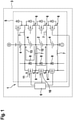
- Figure 1 shows a circuit diagram of an embodiment of a system 1 according to the present invention for discharging a defective battery cell 2 having an internal short circuit of a rechargeable battery unit 3 having several battery cells 2 and 4 connected in series.
- the system 1 comprises a balancing circuit 5 for balancing said battery cells 2 and 4.
- the balancing circuit 5 comprises several power switching converters 6 each being dedicated to one of the battery cells 2 and 4. Several pairs of the power switching converters 6 each share an inductor 7. Further, the balancing circuit 5 comprises several diodes 8 each being dedicated to one of the battery cells 2, 4 and each allowing a charge current to flow through the respective battery cell 2, 4.
- the system 1 comprises a control unit 9 for controlling said balancing circuit 5 and at least one sensor unit (not shown) for detecting, if a short circuit exists in at least one of the battery cells 2 and 4.
- the control unit 9 is capable of controlling the balancing circuit 5 such that, after detection that a short circuit does exist in a battery cell (here the battery cell 2), charge of this defective battery cell 2 is successively transferred to other battery cells 4 by means of the balancing circuit 5.
- the control unit 9 is capable of controlling the balancing circuit 5 such that, after detection that a short circuit does exist in a battery cell (here the battery cell 2), charge of this defective battery 2 cell is transferred to the battery cell 4 whose dedicated power switching converter 6 shares the inductor 7 with the power switching converter 6 being dedicated to the defective battery cell 2. If the short circuit in the defective battery cell 2 is detected, a field-effect transistor 10 of the power switching converter 6 being dedicated to the defective battery cell 2 is turned on for a specific period, and a field-effect transistor 11 of the power switching converter 6 sharing the inductor 7 with the power switching converter 6 being dedicated to the defective battery cell 2 is kept turned off.
- a current indicated by arrow 12 flows through the field-effect transistor 10 and a specific amount of energy is first stored in the inductor 7.
- the field-effect transistor 10 is turned off and the inductor 7 releases its stored energy so that a current indicated by arrow 13 flows through the diode 8 being dedicated to the functional adjacent battery cell 4 and through this battery cell 4.
- this battery cell 4 is charged.
- This procedure can be repeated to discharge the defective battery cell 2.
- the charge added to the functional battery cell 4 can be transferred from this battery cell 4 to the other battery cells 4 in the same manner. Through this, the charge of the defective battery cell 2 can be distributed over the functional battery cells 4 of the rechargeable battery unit 3.
- the control unit 9 may be capable of controlling the balancing circuit 5 such that, after detection that a short circuit does exist in a battery cell (here the battery cell 2), the power switching converter 6 being dedicated to the defective battery cell 2 is operated with a changed switching duty being different from a switching duty provided when no internal short circuit is detected, and that the power switching converter 6 sharing the inductor 7 with the power switching converter 6 being dedicated to the defective battery cell 2 is kept switched off.
- control unit 9 may be capable of controlling the balancing circuit 5 such that, after detection that a short circuit does exist in a battery cell (here the battery cell 2), a switching frequency of the power switching converter 6 being dedicated to the defective battery cell 2 is constant or varied over a discharge period. Furthermore, the control unit 9 may be capable of controlling the balancing circuit 5 such that the power switching converters 6 are not switched at the same time.
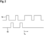
- Figure 2 shows an example of drive signals 14 and 15 applied to gates of the field-effect transistors 10 and 11 of the embodiment of the balancing circuit 5 shown in Figure 1 .
- the upper part of Figure 2 shows the drive signal 14 applied to the field-effect transistor 10
- the lower part of Figure 2 shows the drive signal 15 applied to the field-effect transistor 11.
- the field-effect transistors 10 and 11 are alternately turned on and off. In any case, die field-effect transistors 10 and 11 are not switched at the same time, as shown in Figure 2 .
- t a short circuit is detected in the defective battery cell 2.
- field-effect transistor 10 being dedicated to the defective battery cell 2 is operated with a changed switching duty being different from a switching duty provided when no internal short circuit is detected. Additionally, field-effect transistor 11 sharing the inductor 7 with the power switching converter 6 being dedicated to the defective battery cell 2 is kept switched off.
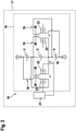
- Figure 3 shows a circuit diagram of a further embodiment of a system 16 according to the present invention for discharging a defective battery cell 2 having an internal short circuit of a rechargeable battery unit 17 having several battery cells 2 and 4 connected in series.
- the system 1 comprises a balancing circuit 18 for balancing said battery cells 2 and 4.
- the balancing circuit 18 comprises several power switching converters 19 each being dedicated to one of the battery cells 2 and 4. Pairs of power switching converters 19 dedicated to neighboring battery cells 2 and 4 are inductively coupled with each other.
- each power switching converter 19 comprises an inductor 20.
- the system 1 comprises a control unit 21 for controlling said balancing circuit 18 and at least one sensor unit (not shown) for detecting, if a short circuit exists in at least one of the battery cells 2 and 4.
- the control unit 21 is capable of controlling the balancing circuit 18 such that, after detection that a short circuit does exist in a battery cell (here the battery cell 2), charge of this defective battery cell 2 is successively transferred to other battery cells 4 by means of the balancing circuit 18.
- the control unit 21 is capable of controlling the balancing circuit 18 such that, after detection that a short circuit does exist in a battery cell (here the battery cell 2), charge of this defective battery cell 2 is transferred to the respective battery cell 4 whose dedicated power switching converter 19 is inductively coupled with the power switching converter 19 being dedicated to the defective battery cell 2. If the short circuit in the defective battery cell 2 is detected, a field-effect transistor 22 of the power switching converter 19 being dedicated to the defective battery cell 2 is turned on for a specific period, and a field-effect transistor 23 of the power switching converter 19 inductively coupled with the power switching converter 19 being dedicated to the defective battery cell 2 is kept turned off.
- the control unit 21 may be capable of controlling the balancing circuit 18 such that, after detection that a short circuit does exist in the defective battery cell 2, the power switching converter 19 being dedicated to the defective battery cell 2 is operated with a changed switching duty being different from a switching duty provided when no internal short circuit is detected, and that the respective power switching converter 23 inductively coupled with the power switching converter 19 being dedicated to the defective battery cell 2 is kept switched off.
- control unit 21 may be capable of controlling the balancing circuit 18 such that, after detection that a short circuit does exist in the defective battery cell 2, a switching frequency of the power switching converter 19 being dedicated to the defective battery cell 2 is constant or varied over a discharge period. Furthermore, the control unit 21 is capable of controlling the balancing circuit 18 such that the power switching converters 19 are not switched at the same time.
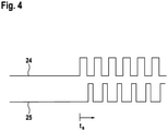
- Figure 4 shows an example of drive signals 24 and 25 applied to gates of the field-effect transistors 22 and 23 of the embodiment of the balancing circuit 18 shown in Figure 3 .
- the upper part of Figure 4 shows the drive signal 24 applied to the field-effect transistor 22, the lower part of Figure 4 shows the drive signal 25 applied to the field-effect transistor 23.
- the field-effect transistors 22 and 23 are turned off. In any case, the field-effect transistors 22 and 23 are not switched at the same time, as shown in Figure 4 .
- t a short circuit is detected in the defective battery cell 2.
- field-effect transistor 22 being dedicated to the defective battery cell 2 is alternately switched on and off, and the field-effect transistor 23 is time-delayed alternately switched on and off.
Landscapes
- Engineering & Computer Science (AREA)
- Manufacturing & Machinery (AREA)
- Chemical & Material Sciences (AREA)
- Chemical Kinetics & Catalysis (AREA)
- Electrochemistry (AREA)
- General Chemical & Material Sciences (AREA)
- Power Engineering (AREA)
- Charge And Discharge Circuits For Batteries Or The Like (AREA)
- Secondary Cells (AREA)
Priority Applications (4)
| Application Number | Priority Date | Filing Date | Title |
|---|---|---|---|
| EP16203922.6A EP3337001B1 (en) | 2016-12-14 | 2016-12-14 | System and method for discharging a defective battery cell |
| PCT/EP2017/081949 WO2018108720A1 (en) | 2016-12-14 | 2017-12-08 | System and method for discharging a defective battery cell |
| CN201780077200.9A CN110073570A (zh) | 2016-12-14 | 2017-12-08 | 用于对有缺陷的电池单元进行放电的系统和方法 |
| JP2019531086A JP2020502973A (ja) | 2016-12-14 | 2017-12-08 | 不良電池セルを放電させるためのシステムおよび方法 |
Applications Claiming Priority (1)
| Application Number | Priority Date | Filing Date | Title |
|---|---|---|---|
| EP16203922.6A EP3337001B1 (en) | 2016-12-14 | 2016-12-14 | System and method for discharging a defective battery cell |
Publications (2)
| Publication Number | Publication Date |
|---|---|
| EP3337001A1 EP3337001A1 (en) | 2018-06-20 |
| EP3337001B1 true EP3337001B1 (en) | 2022-03-02 |
Family
ID=57714359
Family Applications (1)
| Application Number | Title | Priority Date | Filing Date |
|---|---|---|---|
| EP16203922.6A Not-in-force EP3337001B1 (en) | 2016-12-14 | 2016-12-14 | System and method for discharging a defective battery cell |
Country Status (4)
| Country | Link |
|---|---|
| EP (1) | EP3337001B1 (enExample) |
| JP (1) | JP2020502973A (enExample) |
| CN (1) | CN110073570A (enExample) |
| WO (1) | WO2018108720A1 (enExample) |
Families Citing this family (4)
| Publication number | Priority date | Publication date | Assignee | Title |
|---|---|---|---|---|
| US20210296718A1 (en) * | 2020-03-19 | 2021-09-23 | Guangzhou Automobile Group Co., Ltd. | Method and Device for Preventing Battery Thermal Runaway, and Battery System |
| US11626627B2 (en) * | 2020-09-23 | 2023-04-11 | Guangzhou Automobile Group Co., Ltd. | Method and system for preventing battery thermal runaway |
| CN113394849B (zh) * | 2021-07-07 | 2024-05-31 | 惠州市中源新能源有限公司 | 一种多功能锂电池管理系统 |
| US12027675B2 (en) * | 2021-11-23 | 2024-07-02 | Polestar Performance Ab | System and method for rapidly discharging a battery cell during a thermal event |
Family Cites Families (12)
| Publication number | Priority date | Publication date | Assignee | Title |
|---|---|---|---|---|
| US5886512A (en) * | 1996-12-20 | 1999-03-23 | General Electric Company | Low power and wide input voltage range DC to DC switching converter |
| US7378818B2 (en) * | 2002-11-25 | 2008-05-27 | Tiax Llc | Bidirectional power converter for balancing state of charge among series connected electrical energy storage units |
| JP5505375B2 (ja) * | 2011-06-29 | 2014-05-28 | 株式会社豊田自動織機 | セルバランス制御装置及びセルバランス制御方法 |
| US9097774B2 (en) * | 2011-07-14 | 2015-08-04 | Southwest Electronic Energy Corporation | Short detection in battery cells |
| KR101326103B1 (ko) * | 2012-03-29 | 2013-11-06 | 숭실대학교산학협력단 | 배터리 충전량 밸런싱 장치 및 배터리 충전량 밸런싱 시스템 |
| CN202503346U (zh) * | 2012-03-30 | 2012-10-24 | 青岛艾迪森科技有限公司 | 蓄电池智能化自动充电修复装置 |
| DE102012213926A1 (de) * | 2012-08-07 | 2014-02-13 | Robert Bosch Gmbh | Batteriemodul, Batteriemanagementsystem, System zur Versorgung eines Antriebs einer zur Drehmomenterzeugung geeigneten Maschine mit elektrischer Energie und Kraftfahrzeug |
| CN104718681B (zh) | 2012-10-10 | 2018-06-19 | 住友建机株式会社 | 挖土机及挖土机的控制方法 |
| US9325249B2 (en) * | 2013-03-13 | 2016-04-26 | Apple Inc. | Single stage boost-asymmetric LLC |
| JP6271227B2 (ja) * | 2013-11-18 | 2018-01-31 | Fdk株式会社 | バランス補正装置及び蓄電装置 |
| US9774265B2 (en) * | 2014-03-31 | 2017-09-26 | Stmicroelectronics S.R.L. | Wake up management circuit for a power switching converter |
| US20170018817A1 (en) * | 2014-04-02 | 2017-01-19 | Corvus Energy Ltd. | Method, system, and apparatus for inhibiting thermal runaway of a battery cell |
-
2016
- 2016-12-14 EP EP16203922.6A patent/EP3337001B1/en not_active Not-in-force
-
2017
- 2017-12-08 CN CN201780077200.9A patent/CN110073570A/zh active Pending
- 2017-12-08 JP JP2019531086A patent/JP2020502973A/ja active Pending
- 2017-12-08 WO PCT/EP2017/081949 patent/WO2018108720A1/en not_active Ceased
Also Published As
| Publication number | Publication date |
|---|---|
| EP3337001A1 (en) | 2018-06-20 |
| WO2018108720A1 (en) | 2018-06-21 |
| CN110073570A (zh) | 2019-07-30 |
| JP2020502973A (ja) | 2020-01-23 |
Similar Documents
| Publication | Publication Date | Title |
|---|---|---|
| US20200062140A1 (en) | Distributed Battery, Battery Control Method, and Electric Vehicle | |
| US11011920B2 (en) | Energy storage apparatus for engine start-up, method for controlling the same, and vehicle | |
| US8305045B2 (en) | Charge control circuit, battery pack, and charging system | |
| JP5449840B2 (ja) | 充放電制御回路、及び電源装置 | |
| EP3337001B1 (en) | System and method for discharging a defective battery cell | |
| US11502351B2 (en) | Battery pack and control method thereof | |
| US9843184B2 (en) | Voltage conversion apparatus | |
| US8760111B2 (en) | Secondary battery output power controller | |
| US9181683B2 (en) | Electric power control apparatus for construction machine | |
| KR20200024227A (ko) | 듀얼 배터리 시스템을 동작시키기 위한 시스템 및 방법 | |
| US20180083460A1 (en) | System and method of managing battery by using balancing battery | |
| WO2015199178A1 (ja) | バランス補正制御装置、バランス補正システム及び蓄電システム | |
| US10752127B1 (en) | Battery controller and method of battery control | |
| KR20160107173A (ko) | 전기화학 에너지 축전지 및 밸런싱 방법 | |
| US20250392139A1 (en) | Cell balancing apparatus, battery apparatus including the same, and cell balancing method | |
| KR20160097637A (ko) | 차세대 친환경 자동차용 2차 전지 제어장치 | |
| EP3337002B1 (en) | Battery system and control unit for a battery system | |
| JP2019118186A (ja) | バッテリーマネージメントシステム | |
| US11444337B2 (en) | Solid state switch driver circuit for a battery system | |
| EP3708403B1 (en) | Solid state switch driver circuit for a battery system | |
| US12580233B2 (en) | Battery system and method for operating the same | |
| US20230118921A1 (en) | Monitoring device for battery | |
| JP6430100B2 (ja) | ショベル | |
| JP6879135B2 (ja) | 暖機装置システム |
Legal Events
| Date | Code | Title | Description |
|---|---|---|---|
| PUAI | Public reference made under article 153(3) epc to a published international application that has entered the european phase |
Free format text: ORIGINAL CODE: 0009012 |
|
| STAA | Information on the status of an ep patent application or granted ep patent |
Free format text: STATUS: THE APPLICATION HAS BEEN PUBLISHED |
|
| AK | Designated contracting states |
Kind code of ref document: A1 Designated state(s): AL AT BE BG CH CY CZ DE DK EE ES FI FR GB GR HR HU IE IS IT LI LT LU LV MC MK MT NL NO PL PT RO RS SE SI SK SM TR |
|
| AX | Request for extension of the european patent |
Extension state: BA ME |
|
| STAA | Information on the status of an ep patent application or granted ep patent |
Free format text: STATUS: REQUEST FOR EXAMINATION WAS MADE |
|
| 17P | Request for examination filed |
Effective date: 20181220 |
|
| RBV | Designated contracting states (corrected) |
Designated state(s): AL AT BE BG CH CY CZ DE DK EE ES FI FR GB GR HR HU IE IS IT LI LT LU LV MC MK MT NL NO PL PT RO RS SE SI SK SM TR |
|
| RAP1 | Party data changed (applicant data changed or rights of an application transferred) |
Owner name: GS YUASA INTERNATIONAL LTD. |
|
| STAA | Information on the status of an ep patent application or granted ep patent |
Free format text: STATUS: EXAMINATION IS IN PROGRESS |
|
| 17Q | First examination report despatched |
Effective date: 20210630 |
|
| GRAP | Despatch of communication of intention to grant a patent |
Free format text: ORIGINAL CODE: EPIDOSNIGR1 |
|
| STAA | Information on the status of an ep patent application or granted ep patent |
Free format text: STATUS: GRANT OF PATENT IS INTENDED |
|
| RIC1 | Information provided on ipc code assigned before grant |
Ipc: H01M 10/42 20060101ALI20210910BHEP Ipc: H01M 10/44 20060101ALI20210910BHEP Ipc: H02J 7/00 20060101AFI20210910BHEP |
|
| INTG | Intention to grant announced |
Effective date: 20211019 |
|
| GRAS | Grant fee paid |
Free format text: ORIGINAL CODE: EPIDOSNIGR3 |
|
| GRAA | (expected) grant |
Free format text: ORIGINAL CODE: 0009210 |
|
| STAA | Information on the status of an ep patent application or granted ep patent |
Free format text: STATUS: THE PATENT HAS BEEN GRANTED |
|
| AK | Designated contracting states |
Kind code of ref document: B1 Designated state(s): AL AT BE BG CH CY CZ DE DK EE ES FI FR GB GR HR HU IE IS IT LI LT LU LV MC MK MT NL NO PL PT RO RS SE SI SK SM TR |
|
| REG | Reference to a national code |
Ref country code: GB Ref legal event code: FG4D |
|
| REG | Reference to a national code |
Ref country code: CH Ref legal event code: EP Ref country code: AT Ref legal event code: REF Ref document number: 1473050 Country of ref document: AT Kind code of ref document: T Effective date: 20220315 |
|
| REG | Reference to a national code |
Ref country code: DE Ref legal event code: R096 Ref document number: 602016069545 Country of ref document: DE |
|
| REG | Reference to a national code |
Ref country code: IE Ref legal event code: FG4D |
|
| REG | Reference to a national code |
Ref country code: LT Ref legal event code: MG9D |
|
| REG | Reference to a national code |
Ref country code: NL Ref legal event code: MP Effective date: 20220302 |
|
| PG25 | Lapsed in a contracting state [announced via postgrant information from national office to epo] |
Ref country code: SE Free format text: LAPSE BECAUSE OF FAILURE TO SUBMIT A TRANSLATION OF THE DESCRIPTION OR TO PAY THE FEE WITHIN THE PRESCRIBED TIME-LIMIT Effective date: 20220302 Ref country code: RS Free format text: LAPSE BECAUSE OF FAILURE TO SUBMIT A TRANSLATION OF THE DESCRIPTION OR TO PAY THE FEE WITHIN THE PRESCRIBED TIME-LIMIT Effective date: 20220302 Ref country code: NO Free format text: LAPSE BECAUSE OF FAILURE TO SUBMIT A TRANSLATION OF THE DESCRIPTION OR TO PAY THE FEE WITHIN THE PRESCRIBED TIME-LIMIT Effective date: 20220602 Ref country code: LT Free format text: LAPSE BECAUSE OF FAILURE TO SUBMIT A TRANSLATION OF THE DESCRIPTION OR TO PAY THE FEE WITHIN THE PRESCRIBED TIME-LIMIT Effective date: 20220302 Ref country code: HR Free format text: LAPSE BECAUSE OF FAILURE TO SUBMIT A TRANSLATION OF THE DESCRIPTION OR TO PAY THE FEE WITHIN THE PRESCRIBED TIME-LIMIT Effective date: 20220302 Ref country code: ES Free format text: LAPSE BECAUSE OF FAILURE TO SUBMIT A TRANSLATION OF THE DESCRIPTION OR TO PAY THE FEE WITHIN THE PRESCRIBED TIME-LIMIT Effective date: 20220302 Ref country code: BG Free format text: LAPSE BECAUSE OF FAILURE TO SUBMIT A TRANSLATION OF THE DESCRIPTION OR TO PAY THE FEE WITHIN THE PRESCRIBED TIME-LIMIT Effective date: 20220602 |
|
| REG | Reference to a national code |
Ref country code: AT Ref legal event code: MK05 Ref document number: 1473050 Country of ref document: AT Kind code of ref document: T Effective date: 20220302 |
|
| PG25 | Lapsed in a contracting state [announced via postgrant information from national office to epo] |
Ref country code: PL Free format text: LAPSE BECAUSE OF FAILURE TO SUBMIT A TRANSLATION OF THE DESCRIPTION OR TO PAY THE FEE WITHIN THE PRESCRIBED TIME-LIMIT Effective date: 20220302 Ref country code: LV Free format text: LAPSE BECAUSE OF FAILURE TO SUBMIT A TRANSLATION OF THE DESCRIPTION OR TO PAY THE FEE WITHIN THE PRESCRIBED TIME-LIMIT Effective date: 20220302 Ref country code: GR Free format text: LAPSE BECAUSE OF FAILURE TO SUBMIT A TRANSLATION OF THE DESCRIPTION OR TO PAY THE FEE WITHIN THE PRESCRIBED TIME-LIMIT Effective date: 20220603 Ref country code: FI Free format text: LAPSE BECAUSE OF FAILURE TO SUBMIT A TRANSLATION OF THE DESCRIPTION OR TO PAY THE FEE WITHIN THE PRESCRIBED TIME-LIMIT Effective date: 20220302 |
|
| PG25 | Lapsed in a contracting state [announced via postgrant information from national office to epo] |
Ref country code: NL Free format text: LAPSE BECAUSE OF FAILURE TO SUBMIT A TRANSLATION OF THE DESCRIPTION OR TO PAY THE FEE WITHIN THE PRESCRIBED TIME-LIMIT Effective date: 20220302 |
|
| PG25 | Lapsed in a contracting state [announced via postgrant information from national office to epo] |
Ref country code: SM Free format text: LAPSE BECAUSE OF FAILURE TO SUBMIT A TRANSLATION OF THE DESCRIPTION OR TO PAY THE FEE WITHIN THE PRESCRIBED TIME-LIMIT Effective date: 20220302 Ref country code: SK Free format text: LAPSE BECAUSE OF FAILURE TO SUBMIT A TRANSLATION OF THE DESCRIPTION OR TO PAY THE FEE WITHIN THE PRESCRIBED TIME-LIMIT Effective date: 20220302 Ref country code: RO Free format text: LAPSE BECAUSE OF FAILURE TO SUBMIT A TRANSLATION OF THE DESCRIPTION OR TO PAY THE FEE WITHIN THE PRESCRIBED TIME-LIMIT Effective date: 20220302 Ref country code: PT Free format text: LAPSE BECAUSE OF FAILURE TO SUBMIT A TRANSLATION OF THE DESCRIPTION OR TO PAY THE FEE WITHIN THE PRESCRIBED TIME-LIMIT Effective date: 20220704 Ref country code: EE Free format text: LAPSE BECAUSE OF FAILURE TO SUBMIT A TRANSLATION OF THE DESCRIPTION OR TO PAY THE FEE WITHIN THE PRESCRIBED TIME-LIMIT Effective date: 20220302 Ref country code: CZ Free format text: LAPSE BECAUSE OF FAILURE TO SUBMIT A TRANSLATION OF THE DESCRIPTION OR TO PAY THE FEE WITHIN THE PRESCRIBED TIME-LIMIT Effective date: 20220302 Ref country code: AT Free format text: LAPSE BECAUSE OF FAILURE TO SUBMIT A TRANSLATION OF THE DESCRIPTION OR TO PAY THE FEE WITHIN THE PRESCRIBED TIME-LIMIT Effective date: 20220302 |
|
| PG25 | Lapsed in a contracting state [announced via postgrant information from national office to epo] |
Ref country code: IS Free format text: LAPSE BECAUSE OF FAILURE TO SUBMIT A TRANSLATION OF THE DESCRIPTION OR TO PAY THE FEE WITHIN THE PRESCRIBED TIME-LIMIT Effective date: 20220702 Ref country code: AL Free format text: LAPSE BECAUSE OF FAILURE TO SUBMIT A TRANSLATION OF THE DESCRIPTION OR TO PAY THE FEE WITHIN THE PRESCRIBED TIME-LIMIT Effective date: 20220302 |
|
| REG | Reference to a national code |
Ref country code: DE Ref legal event code: R097 Ref document number: 602016069545 Country of ref document: DE |
|
| PLBE | No opposition filed within time limit |
Free format text: ORIGINAL CODE: 0009261 |
|
| STAA | Information on the status of an ep patent application or granted ep patent |
Free format text: STATUS: NO OPPOSITION FILED WITHIN TIME LIMIT |
|
| PG25 | Lapsed in a contracting state [announced via postgrant information from national office to epo] |
Ref country code: DK Free format text: LAPSE BECAUSE OF FAILURE TO SUBMIT A TRANSLATION OF THE DESCRIPTION OR TO PAY THE FEE WITHIN THE PRESCRIBED TIME-LIMIT Effective date: 20220302 |
|
| PGFP | Annual fee paid to national office [announced via postgrant information from national office to epo] |
Ref country code: DE Payment date: 20221102 Year of fee payment: 7 |
|
| 26N | No opposition filed |
Effective date: 20221205 |
|
| PG25 | Lapsed in a contracting state [announced via postgrant information from national office to epo] |
Ref country code: SI Free format text: LAPSE BECAUSE OF FAILURE TO SUBMIT A TRANSLATION OF THE DESCRIPTION OR TO PAY THE FEE WITHIN THE PRESCRIBED TIME-LIMIT Effective date: 20220302 |
|
| P01 | Opt-out of the competence of the unified patent court (upc) registered |
Effective date: 20230522 |
|
| PG25 | Lapsed in a contracting state [announced via postgrant information from national office to epo] |
Ref country code: IT Free format text: LAPSE BECAUSE OF FAILURE TO SUBMIT A TRANSLATION OF THE DESCRIPTION OR TO PAY THE FEE WITHIN THE PRESCRIBED TIME-LIMIT Effective date: 20220302 |
|
| REG | Reference to a national code |
Ref country code: CH Ref legal event code: PL |
|
| GBPC | Gb: european patent ceased through non-payment of renewal fee |
Effective date: 20221214 |
|
| REG | Reference to a national code |
Ref country code: BE Ref legal event code: MM Effective date: 20221231 |
|
| PG25 | Lapsed in a contracting state [announced via postgrant information from national office to epo] |
Ref country code: LU Free format text: LAPSE BECAUSE OF NON-PAYMENT OF DUE FEES Effective date: 20221214 |
|
| PG25 | Lapsed in a contracting state [announced via postgrant information from national office to epo] |
Ref country code: LI Free format text: LAPSE BECAUSE OF NON-PAYMENT OF DUE FEES Effective date: 20221231 Ref country code: IE Free format text: LAPSE BECAUSE OF NON-PAYMENT OF DUE FEES Effective date: 20221214 Ref country code: GB Free format text: LAPSE BECAUSE OF NON-PAYMENT OF DUE FEES Effective date: 20221214 Ref country code: CH Free format text: LAPSE BECAUSE OF NON-PAYMENT OF DUE FEES Effective date: 20221231 |
|
| PG25 | Lapsed in a contracting state [announced via postgrant information from national office to epo] |
Ref country code: FR Free format text: LAPSE BECAUSE OF NON-PAYMENT OF DUE FEES Effective date: 20221231 Ref country code: BE Free format text: LAPSE BECAUSE OF NON-PAYMENT OF DUE FEES Effective date: 20221231 |
|
| PG25 | Lapsed in a contracting state [announced via postgrant information from national office to epo] |
Ref country code: HU Free format text: LAPSE BECAUSE OF FAILURE TO SUBMIT A TRANSLATION OF THE DESCRIPTION OR TO PAY THE FEE WITHIN THE PRESCRIBED TIME-LIMIT; INVALID AB INITIO Effective date: 20161214 |
|
| PG25 | Lapsed in a contracting state [announced via postgrant information from national office to epo] |
Ref country code: CY Free format text: LAPSE BECAUSE OF FAILURE TO SUBMIT A TRANSLATION OF THE DESCRIPTION OR TO PAY THE FEE WITHIN THE PRESCRIBED TIME-LIMIT Effective date: 20220302 |
|
| PG25 | Lapsed in a contracting state [announced via postgrant information from national office to epo] |
Ref country code: MK Free format text: LAPSE BECAUSE OF FAILURE TO SUBMIT A TRANSLATION OF THE DESCRIPTION OR TO PAY THE FEE WITHIN THE PRESCRIBED TIME-LIMIT Effective date: 20220302 |
|
| PG25 | Lapsed in a contracting state [announced via postgrant information from national office to epo] |
Ref country code: MC Free format text: LAPSE BECAUSE OF FAILURE TO SUBMIT A TRANSLATION OF THE DESCRIPTION OR TO PAY THE FEE WITHIN THE PRESCRIBED TIME-LIMIT Effective date: 20220302 |
|
| PG25 | Lapsed in a contracting state [announced via postgrant information from national office to epo] |
Ref country code: MC Free format text: LAPSE BECAUSE OF FAILURE TO SUBMIT A TRANSLATION OF THE DESCRIPTION OR TO PAY THE FEE WITHIN THE PRESCRIBED TIME-LIMIT Effective date: 20220302 |
|
| REG | Reference to a national code |
Ref country code: DE Ref legal event code: R119 Ref document number: 602016069545 Country of ref document: DE |
|
| PG25 | Lapsed in a contracting state [announced via postgrant information from national office to epo] |
Ref country code: MT Free format text: LAPSE BECAUSE OF FAILURE TO SUBMIT A TRANSLATION OF THE DESCRIPTION OR TO PAY THE FEE WITHIN THE PRESCRIBED TIME-LIMIT Effective date: 20220302 |
|
| PG25 | Lapsed in a contracting state [announced via postgrant information from national office to epo] |
Ref country code: DE Free format text: LAPSE BECAUSE OF NON-PAYMENT OF DUE FEES Effective date: 20240702 |
|
| PG25 | Lapsed in a contracting state [announced via postgrant information from national office to epo] |
Ref country code: DE Free format text: LAPSE BECAUSE OF NON-PAYMENT OF DUE FEES Effective date: 20240702 |
|
| PG25 | Lapsed in a contracting state [announced via postgrant information from national office to epo] |
Ref country code: TR Free format text: LAPSE BECAUSE OF FAILURE TO SUBMIT A TRANSLATION OF THE DESCRIPTION OR TO PAY THE FEE WITHIN THE PRESCRIBED TIME-LIMIT Effective date: 20220302 |