EP3336289B1 - Closure assembly for a double-leaf door - Google Patents
Closure assembly for a double-leaf door Download PDFInfo
- Publication number
- EP3336289B1 EP3336289B1 EP17201648.7A EP17201648A EP3336289B1 EP 3336289 B1 EP3336289 B1 EP 3336289B1 EP 17201648 A EP17201648 A EP 17201648A EP 3336289 B1 EP3336289 B1 EP 3336289B1
- Authority
- EP
- European Patent Office
- Prior art keywords
- lock bolt
- actuating element
- lock
- leaf
- actuating
- Prior art date
- Legal status (The legal status is an assumption and is not a legal conclusion. Google has not performed a legal analysis and makes no representation as to the accuracy of the status listed.)
- Active
Links
- 230000000903 blocking effect Effects 0.000 claims description 45
- 210000001061 forehead Anatomy 0.000 description 3
- 230000007704 transition Effects 0.000 description 3
- 238000004026 adhesive bonding Methods 0.000 description 2
- 238000006073 displacement reaction Methods 0.000 description 2
- 238000000034 method Methods 0.000 description 2
- 238000005476 soldering Methods 0.000 description 2
- 238000003466 welding Methods 0.000 description 2
- 238000013475 authorization Methods 0.000 description 1
- 238000011161 development Methods 0.000 description 1
- 230000018109 developmental process Effects 0.000 description 1
- 230000000694 effects Effects 0.000 description 1
- IHQKEDIOMGYHEB-UHFFFAOYSA-M sodium dimethylarsinate Chemical class [Na+].C[As](C)([O-])=O IHQKEDIOMGYHEB-UHFFFAOYSA-M 0.000 description 1
Images


Classifications
-
- E—FIXED CONSTRUCTIONS
- E05—LOCKS; KEYS; WINDOW OR DOOR FITTINGS; SAFES
- E05B—LOCKS; ACCESSORIES THEREFOR; HANDCUFFS
- E05B15/00—Other details of locks; Parts for engagement by bolts of fastening devices
- E05B15/0053—Other details of locks; Parts for engagement by bolts of fastening devices means providing a stable, i.e. indexed, position of lock parts
-
- E—FIXED CONSTRUCTIONS
- E05—LOCKS; KEYS; WINDOW OR DOOR FITTINGS; SAFES
- E05B—LOCKS; ACCESSORIES THEREFOR; HANDCUFFS
- E05B15/00—Other details of locks; Parts for engagement by bolts of fastening devices
- E05B15/10—Bolts of locks or night latches
- E05B15/101—Spring-retracted bolts
-
- E—FIXED CONSTRUCTIONS
- E05—LOCKS; KEYS; WINDOW OR DOOR FITTINGS; SAFES
- E05B—LOCKS; ACCESSORIES THEREFOR; HANDCUFFS
- E05B15/00—Other details of locks; Parts for engagement by bolts of fastening devices
- E05B15/10—Bolts of locks or night latches
- E05B15/102—Bolts having movable elements
-
- E—FIXED CONSTRUCTIONS
- E05—LOCKS; KEYS; WINDOW OR DOOR FITTINGS; SAFES
- E05B—LOCKS; ACCESSORIES THEREFOR; HANDCUFFS
- E05B65/00—Locks or fastenings for special use
- E05B65/10—Locks or fastenings for special use for panic or emergency doors
- E05B65/1086—Locks with panic function, e.g. allowing opening from the inside without a ley even when locked from the outside
-
- E—FIXED CONSTRUCTIONS
- E05—LOCKS; KEYS; WINDOW OR DOOR FITTINGS; SAFES
- E05C—BOLTS OR FASTENING DEVICES FOR WINGS, SPECIALLY FOR DOORS OR WINDOWS
- E05C7/00—Fastening devices specially adapted for two wings
- E05C7/04—Fastening devices specially adapted for two wings for wings which abut when closed
Definitions
- the invention relates to a locking arrangement for a double-leaf door of the type mentioned in the preamble of patent claim 1 and a corresponding double-leaf door with such a locking arrangement.
- Double-leaf doors with a moving leaf and a fixed leaf as well as a locking arrangement with a full panic function must be able to be opened safely when locked even if the fixed leaf is opened first. So that the locked deadbolt of the active leaf cannot jam in a locking plate of the passive leaf, the deadbolt is moved from the locked position to a locked position by a special mechanism in the strike box of the passive leaf when a handle and/or a panic bar of the passive leaf is actuated. A blockage of the lock bolt must be unlocked beforehand. This is done by actuating an unlocking element, which is usually integrated in the lock bolt and protrudes beyond its face in the direction of the strike box. However, this unlocking element above can be manipulated and reduces the security class of such locks.
- a panic lock with a bolt that can be locked forwards and backwards in a bolt displacement direction, in particular by a locking element of a lock cylinder, which is held in the pre-closed position by a tumbler and which carries a trigger that can be displaced in a bolt displacement direction, which, when its front edge is acted upon, causes it to shift into Bolt closing direction releases the tumbler to enable a bolt shift back.
- the bolt In the area of its forehead, the bolt forms a niche that is flanked by its face and is open to the forehead of the bolt, in which the trigger lies, with the niche being open on both broad sides of the bolt and the front edge for releasing the tumbler over the one in the forehead of the bolt lying edge must be shifted into the niche so that the front edge of the trigger is in the niche when the guard locking is released.
- a panic lock with a housing a tumbler arranged therein for a bolt and a release lug guided in the closing direction in the bolt is known.
- the release lug is locked by at least one projection arranged on the tumbler.
- the release lug and the tumbler are arranged in the same plane, the tumbler having a hook-shaped projection on its edge facing the bolt, which engages in an associated recess of the release lug when the bolt is locked, and a guide lug guided on a cam of the release lug.
- the invention is based on the object of specifying a locking arrangement for a double-leaf door and a corresponding double-leaf door which, with the same panic functionality, enables improved protection against forced entry and/or burglary.
- This object is achieved by the features of the locking arrangement for a double-leaf door according to patent claim 1 and by the features of the double-leaf door according to patent claim 7.
- Embodiments of a locking arrangement according to the invention for a double-leaf door include a lock case with a lock bolt and a blocking device, which secures the lock bolt in a locked state against being converted into a locked state, and a strike case with a locking plate, into which the lock bolt in the locked state is at least partially intervenes.
- a strike box By actuating the strike box to perform a panic function, an unlocking element guided in the lock bolt unblocks the lock bolt and a first actuating element transfers the lock bolt from the locked state to the locked state, in which the lock bolt releases the locking plate.
- the unlocking element is completely embedded in the lock bolt in the direction of the lock bolt, regardless of the closed state of the lock bolt, with actuation of the lock bolt to execute the panic function, a second actuating element arranged in the lock bolt moving the unlocking element in the direction of blocking and unblocking the lock bolt.
- a double-leaf door with an active leaf and a passive leaf and such a locking arrangement which includes a lock case with a lock bolt and a blocking device, which secures the lock bolt in a locked state against being converted into a locked state, and a strike case with a striker plate , in which the lock bolt at least partially engages in the locked state.
- the unlocking element does not protrude beyond the lock bolt in the direction of the strike box, but is embedded in the body of the lock bolt. This advantageously prevents or at least makes it more difficult for the locking bolt to be unblocked without authorization. This has an advantageous effect with regard to burglary protection, so that embodiments of the locking arrangement according to the invention can be classified in a higher security class.
- An additional advantage is that the unlocking element embedded in the lock bolt does not have to be retracted when the bolt is locked in order to prevent a collision with the locking plate. This additional mechanism does not apply to the integrated unlocking element.
- the lock case with lock bolt and blocking device can be arranged on the active leaf and the lock case with locking plate can be arranged on the passive leaf.
- a handle and/or a panic bar of the passive leaf can act on the first actuating element via at least one pivoting leaf and actuate the strike box, which then actuates the lock case of the active leaf to unlock the door.
- a handle and/or a panic bar of the active leaf can act on the blocking and the lock bolt to execute the panic function and directly actuate the lock case.
- embodiments of the present invention provide a double-leaf door with a full panic function which, in the closed state, can be unlocked and opened both via the handle and/or panic bar of the active leaf and via the handle and/or panic bar of the passive leaf.
- the blocking can be implemented as a blocking element which is firmly connected to a movable lock link and can form a stop for the lock bolt when the lock bolt is in the locked state.
- the unlocking element can, for example, be designed with an actuating bevel, which can lift the blocking element onto an inclined surface of the lock bolt.
- an inexpensive and simple mechanism for releasing the blocking of the lock bolt can be implemented in an advantageous manner.
- the lock link can have a guide element which rests against a contour of the lock bolt during the transfer of the lock bolt into the locked state and can move the lock link perpendicular to the lock bolt up to a stop. As a result, further movement of the lock bolt beyond the locked state can be prevented in an advantageous manner.
- the second actuating element is guided in the first actuating element so that it can move axially.
- the first actuating element can be moved between an initial position and an end position, with the second actuating element projecting beyond the first actuating element in the direction of the lock bolt until it reaches the end position and acting on the unlocking element via an opening in the lock bolt before the first actuating element hits the lock bolt.
- first actuating element can completely accommodate the second actuating element when it reaches its end position, with the end position of the first actuating element corresponding to the closed state of the lock bolt.
- the first actuating element can be designed, for example, as a slide and the second actuating element can be designed, for example, as an actuating pin, which is in a corresponding Recess in the slide is guided to be axially movable.
- the handle and/or the panic bar of the fixed leaf can act, for example via two pivoting levers, on a first actuating element designed as a slide and actuate the strike box.
- the handle and/or the panic bar of the passive leaf can act on only one pivoting leaf, with the first actuating element being designed as an arm of this pivoting lever and being able to actuate the strike box.
- a double-leaf door in the exemplary embodiments shown comprises a moving leaf 3 and a fixed leaf 5 and a locking arrangement 1, 1A.
- the locking arrangement 1, 1A includes a lock case 10 with a lock bolt 14 and a block, which is designed as a blocking element 16.1 in the illustrated embodiment.
- the blocking secures the lock bolt 14 in an in Figures 1 to 4 , 11 and 12 , illustrated excluded state against transition to an enclosed state.
- the locking arrangement 1, 1A comprises a strike box 20 with a locking plate 22.1, in which the lock bolt 14 engages at least partially in the locked state.
- an unlocking element 14.1 guided in the lock bolt 14 unblocks the lock bolt 14, and a first actuating element 24, 24A transfers the lock bolt 14 from the locked state to the locked state, in which the lock bolt 14 Closing plate 22.1 releases and the door is unlocked.
- the locked state is in Figures 9, 10 and 14 shown.
- the unlocking element 14.1 is completely embedded in the lock bolt 14 in the direction of the strike box 20, regardless of the closed state of the lock bolt 14, with the actuation of the strike box 20 for executing the panic function, a second actuating element 24.1, 24.1A arranged in the strike box 20 moving the unlocking element 14.1 in the direction of blocking moves and the blocking of the lock bolt 14 cancels.
- the lock case 10 with the lock bolt 14 and blocking device which are arranged inside a housing 12, is arranged on the active leaf 3.
- the locking plate 22.1 has unspecified openings for engaging the lock bolt 14 and cross latches 7, 9.
- a first cross latch 7 is arranged above the lock bolt 14, and a second cross latch 9 is arranged below the lock bolt.
- a handle (not shown) and/or a panic bar (not shown) of the fixed leaf 5 act on the first actuating element 24, 24A and actuate the strike box 20, which then actuates the lock case 10.
- a handle (not shown) and/or a panic bar (not shown) of the active leaf 3 act on the blocking and the lock bolt 14 and actuate the lock case 10 directly.
- the double-leaf door can be unlocked and opened by the panic function in the closed state both via the handle and/or panic bar of the active leaf 3 and via the handle and/or panic bar of the passive leaf 5.
- the blocking is designed as a blocking element 16.1, which is firmly connected to a movable lock link 16, shown transparently, and forms a stop for the lock bolt 14 when the lock bolt 14 is in the locked state.
- the lock link 16 is movably mounted in the housing 12 of the lock case 10 and can be moved perpendicular to the sliding movement of the lock bolt 14 to release the blocking.
- the sliding movement of the lock bolt 14 runs horizontally and the movement of the lock link 16 runs vertically upwards.
- the person skilled in the art can also use other suitable embodiments for blocking the lock bolt 14 .
- the lock bolt 14 has a bevel 14.2 and a shoulder on its end facing the blocking, on which the blocking element 16.1 rests.
- the unlocking element 14.1 has an actuating slope at its end facing the blocking, which, when the unlocking element 14.1 moves in the direction of blocking, emerges from an opening at a lower end of the inclined surface 14.2 of the lock bolt 14 and lifts the blocking element 16.1 onto the inclined surface of the lock bolt. This moves the lock setting 16 also up.
- the lock link 16 in the illustrated exemplary embodiments has a guide element 16.2, which is also firmly connected to the lock link 16 and, as a result of the upward movement, comes to rest on a sloping contour 16.3 of the lock bolt 14.
- the contour 16.3 of the lock bolt 14 guides the guide element 16.2, so that the lock link 16 is moved further upwards perpendicularly to the lock bolt 14 until a stop (not shown in detail) is reached and the lock bolt 14 enters the locked state. This can advantageously prevent further movement of the lock bolt 14 beyond the locked state.
- the second actuating element 24.1 is designed as an actuating pin in the illustrated embodiment of the locking arrangement 1 and is guided in an axially movable manner in the first actuating element 24, which is designed as a slide.
- the first actuating element 24 designed as a slide is mounted via two pivoted levers 26, each of which is mounted in a housing 22 of the strike box 20 so that it can pivot about a corresponding pivot axis 26.1 and is coupled at one end to the first actuating element designed as a slide 24 , movable between an initial position and an end position.
- the other end of the pivoting lever 26 is coupled to the handle (not shown) and/or the panic bar (not shown) of the fixed leaf 5 .
- the second actuating element 24.1 designed as an actuating pin protrudes beyond the first actuating element 24 designed as a slide until it reaches the end position in the direction of the lock bolt 14. Therefore, before a contact section 24.2 of the first actuating element 24 designed as a slide hits the lock bolt 14, the second actuating element 24.1 designed as an actuating pin can act on the unlocking element 14.1 via an opening in the lock bolt 14 and unblock the lock bolt 14.
- the second actuating element 24.1 acts on an L-shaped end region 14.5 of the unlocking element 14.1, the end region 14.5 being supported on a return spring 14.4 which acts against the second actuating element 24.1.
- the first actuating element 24 designed as a slide fully accommodates the second actuating element 24.1 designed as an actuating pin, with the end position of the first actuating element 24 corresponding to the closed state of the lock bolt 14.
- the first actuating element 24 is designed as a slide and the second actuating element 24.1 as an actuating pin.
- first actuating element 24 and the second actuating element 24.1 can also use other suitable embodiments for the first actuating element 24 and the second actuating element 24.1.
- the counter box 20 is operated in the fixed leaf 5 via the handle not shown and / or the panic bar not shown.
- the two pivoted levers 26 are each pivoted about a corresponding pivot axis 26.1 and the first actuating element 24, designed as a slide, moves with the contact section 24.2 and the second actuating element 24.1, designed as an actuating pin, towards the locked and blocked lock bolt 14.
- the strike box 20 in the passive leaf 5 is further operated via the handle (not shown) and/or the panic bar (not shown) and the second actuating element 24.1, designed as an actuating pin, in the strike box 20 is operated via the swivel lever 26 and the first actuating element, designed as a slide 24 moves further in the direction of the lock bolt 14 and penetrates into an opening in the lock bolt 14 .
- the unlocking element 14.1 is moved against the force of the return spring 14.4 in the direction of the blocking element 16.1, so that it is lifted with the lock link 16.
- the lock bolt 14 is released for transfer to the locked state.
- the first actuating element 24 embodied as a slide rests flat on the end face of the lock bolt 14 with its contact section 24.2.
- the strike box 20 in the passive leaf 5 continues to be operated via the handle (not shown) and/or the panic bar (not shown) and the first actuating element 24, designed as a slide, in the strike box 20 is moved further via the pivoted lever 26 and pushes the lock bolt 14 further back in the direction of the locked state, with the second actuating element 24.1 designed as an actuating pin still protruding into the lock bolt 14.
- the strike box 20 in the passive leaf 5 continues to be operated via the handle (not shown) and/or the panic bar (not shown) and the first actuating element 24, designed as a slide, in the strike box 20 is moved further via the pivoted lever 26 and pushes the lock bolt 14 further back toward the trapped state.
- the second actuating element 24.1 designed as an actuating pin is blocked in the strike box 20 while the first actuating element 24 designed as a slide moves further in the strike box 20 towards the end position.
- the imposition of the second actuating element 24.1, which is designed as an actuating pin, on the lock bolt 14 is canceled and the unlocking element 14.1 is moved back into the starting position by the return spring 14.4, so that the L-shaped end region 14.5 ends with the end face of the lock bolt 14.
- the lock bolt 14 snaps into place when locked, so that the fixed leaf 5 and/or the active leaf 3 can be opened.
- the second actuating element 24.1A in the illustrated example of a locking arrangement 1A not according to the invention is designed as an actuating lug which is connected to the first actuating element 24A.
- the first actuating element 24A and the second actuating element 24.1A are designed in one piece, with the second actuating element 24.1A designed as an actuating lug being formed onto the first actuating element 24A.
- the first actuating element 24A forms an arm of a pivoting lever 26A, which is mounted in a housing 22 of the counter box 20 so as to be pivotable about a corresponding pivot axis 26.1A.
- the second actuating element 24.1A can be designed as a separate component and connected to the first actuating element 24A by means of screws, adhesive bonding, welding, soldering or another suitable connection technique.
- the first actuating element 24A can also be designed as a separate component and connected to the pivoted lever 26A by screws, adhesive bonding, welding, soldering or by another suitable connection technique.
- one end of the pivoted lever can be pivoted with the first actuating element 24A and the second actuating element 24.1A and a corresponding contact section 24.2A between an initial position and an end position.
- the other end of the swing arm 26A is coupled to the handle (not shown) and/or the panic bar (not shown) of the fixed leaf 5 .
- the second actuating element 24.1A designed as an actuating lug, projects beyond the contact section 24.2A of the first actuating element 24A until it reaches the end position in the direction of the lock bolt 14.
- the second actuating element 24.1A can act on the unlocking element 14.1 via an opening in the lock bolt 14 before the contact section 24.2A of the first actuating element 24 strikes the lock bolt 14 and unblock the lock bolt 14.
- the second actuating element 24.1A acts analogously to the exemplary embodiment against the force of the return spring 14.4 on the L-shaped end area 14.5 of the unlocking element 14.1.
- the blocking element 16.1 of the lock link 16 in the illustrated locked state of the double-leaf door secures the locked lock bolt 14 against being manually pushed back into the locked state, analogously to the exemplary embodiment.
- the counter box 20 is operated in the fixed leaf 5 via the handle not shown and / or the panic bar not shown.
- the pivoted lever 26A is pivoted about a corresponding pivot axis 26.1A and the first actuating element 24 moves with the contact section 24.2A and the second actuating element 24.1A designed as an actuating lug towards the locked and blocked lock bolt 14.
- strike box 20 in passive leaf 5 continues to be operated via the handle (not shown) and/or panic bar (not shown) and second actuating element 24.1A, designed as an actuating lug, in strike box 20 is further operated via pivoted lever 26A and first actuating element 24 moves in the direction of the lock bolt 14 and penetrates into an opening in the lock bolt 14 .
- the unlocking element 14.1 is moved against the force of the return spring 14.4 in the direction of the blocking element 16.1, so that it is lifted with the lock link 16.
- the lock bolt 14 is released for transfer to the locked state.
- the contact section 24.2A of the first actuating element 24A rests against the end face of the lock bolt 14 after the blocking of the lock bolt 14 has been removed.
- the strike box 20 in the passive leaf 5 continues to be operated via the handle (not shown) and/or the panic bar (not shown) and the first actuating element 24A in the strike box 20 is moved further via the pivoted lever 26A and pushes the lock bolt 14 further back in towards the closed state.
- the second actuating element 24.1A in the strike box 20 pivots out of the opening in the lock bolt 14 while the first actuating element 24 in the strike box 20 moves further towards the end position.
- the unlocking element 14.1 is moved back into the initial position by the return spring 14.4, so that the L-shaped end region 14.5 ends with the end face of the lock bolt 14, analogously to the exemplary embodiment.
- the lock bolt 14 snaps into place when locked, so that the fixed leaf 5 and/or the active leaf 3 can be opened. If required, the lock bolt 14 can have a cutout upwards and/or downwards at the end facing the first actuating element 24A, which increases the range of rotation of the pivoted lever 26A with the first actuating element 24A and the second actuating element 24.1A.
- Embodiments of the locking arrangement according to the invention for a double-leaf door advantageously provide improved protection against forced entry and/or burglary with the same panic functionality.
Description
Die Erfindung betrifft eine Verriegelungsanordnung für eine zweiflügelige Tür der im Oberbegriff des Patentanspruchs 1 genannten Art sowie eine korrespondierende zweiflügelige Tür mit einer solchen Verriegelungsanordnung.The invention relates to a locking arrangement for a double-leaf door of the type mentioned in the preamble of
Zweiflügelige Türen mit einem Gangflügel und einem Standflügel sowie einer Verriegelungsanordnung mit einer Vollpanikfunktion müssen sich im verschlossenen Zustand auch dann sicher öffnen lassen, wenn zuerst der Standflügel geöffnet wird. Damit der ausgeschlossene Schlossriegel des Gangflügels nicht in einer Schließplatte des Standflügels verkanten kann, wird der Schlossriegel bei Betätigung eines Drückers und/oder einer Panikstange des Standflügels durch eine spezielle Mechanik im Gegenkasten des Standflügels von der ausgeschlossenen Stellung in eine eingeschlossene Stellung bewegt. Zuvor muss eine Blockierung des Schlossriegels entsperrt werden. Dies geschieht durch Betätigen eines Entriegelungselements, welches üblicherweise im Schlossriegel integriert ist und über dessen Stirnfläche in Richtung Gegenkasten hervorsteht. Dieses vorstehende Entriegelungselement kann jedoch manipuliert werden und reduziert die Sicherheitsklasse solcher Schlösser.Double-leaf doors with a moving leaf and a fixed leaf as well as a locking arrangement with a full panic function must be able to be opened safely when locked even if the fixed leaf is opened first. So that the locked deadbolt of the active leaf cannot jam in a locking plate of the passive leaf, the deadbolt is moved from the locked position to a locked position by a special mechanism in the strike box of the passive leaf when a handle and/or a panic bar of the passive leaf is actuated. A blockage of the lock bolt must be unlocked beforehand. This is done by actuating an unlocking element, which is usually integrated in the lock bolt and protrudes beyond its face in the direction of the strike box. However, this unlocking element above can be manipulated and reduces the security class of such locks.
Aus der
Aus der
Der Erfindung liegt die Aufgabe zugrunde, eine Verriegelungsanordnung für eine zweiflügelige Tür und eine korrespondierende zweiflügelige Tür anzugeben, welche bei gleicher Panikfunktionalität einen verbesserten Aufbruch- und/oder Einbruchschutz ermöglicht. Diese Aufgabe wird durch die Merkmale der Verriegelungsanordnung für eine zweiflügelige Tür nach Patentanspruch 1 und durch die Merkmale der zweiflügeligen Tür nach Patentanspruch 7 gelöst.The invention is based on the object of specifying a locking arrangement for a double-leaf door and a corresponding double-leaf door which, with the same panic functionality, enables improved protection against forced entry and/or burglary. This object is achieved by the features of the locking arrangement for a double-leaf door according to
Vorteilhafte Ausgestaltungen und Weiterbildungen der Erfindung sind in den übrigen Ansprüchen angegeben.Advantageous configurations and developments of the invention are specified in the remaining claims.
Ausführungsformen einer erfindungsgemäße Verriegelungsanordnung für eine zweiflügelige Tür umfassen einen Schlosskasten mit einem Schlossriegel und einer Blockierung, welche den Schlossriegel in einem ausgeschlossenen Zustand gegen eine Überführung in einen eingeschlossenen Zustand sichert, und einen Gegenkasten mit einer Schließplatte, in welche der Schlossriegel im ausgeschlossenen Zustand zumindest teilweise eingreift. Durch eine Betätigung des Gegenkastens zur Ausführung einer Panikfunktion hebt ein im Schlossriegel geführtes Entriegelungselement die Blockierung des Schlossriegels auf und ein erstes Betätigungselement überführt den Schlossriegel vom ausgeschlossenen Zustand in den eingeschlossenen Zustand, in welchem der Schlossriegel die Schließplatte freigibt. Erfindungsgemäß ist das Entriegelungselement unabhängig vom Schließzustand des Schlossriegels in Richtung Gegenkasten vollständig in den Schlossriegel eingebettet, wobei durch die Betätigung des Gegenkastens zur Ausführung der Panikfunktion ein im Gegenkasten angeordnetes zweites Betätigungselement das Entriegelungselement in Richtung Blockierung bewegt und die Blockierung des Schlossriegels aufhebt.Embodiments of a locking arrangement according to the invention for a double-leaf door include a lock case with a lock bolt and a blocking device, which secures the lock bolt in a locked state against being converted into a locked state, and a strike case with a locking plate, into which the lock bolt in the locked state is at least partially intervenes. By actuating the strike box to perform a panic function, an unlocking element guided in the lock bolt unblocks the lock bolt and a first actuating element transfers the lock bolt from the locked state to the locked state, in which the lock bolt releases the locking plate. According to the invention, the unlocking element is completely embedded in the lock bolt in the direction of the lock bolt, regardless of the closed state of the lock bolt, with actuation of the lock bolt to execute the panic function, a second actuating element arranged in the lock bolt moving the unlocking element in the direction of blocking and unblocking the lock bolt.
Zudem wird eine zweiflügelige Tür mit einem Gangflügel und einem Standflügel und einer solchen Verriegelungsanordnung vorgeschlagen, welche einen Schlosskasten mit einem Schlossriegel und einer Blockierung, welche den Schlossriegel in einem ausgeschlossenen Zustand gegen eine Überführung in einen eingeschlossenen Zustand sichert, und einen Gegenkasten mit einer Schließplatte umfasst, in welche der Schlossriegel im ausgeschlossenen Zustand zumindest teilweise eingreift. Durch eine Betätigung des Gegenkastens zur Ausführung einer Panikfunktion hebt ein im Schlossriegel geführtes Entriegelungselement die Blockierung des Schlossriegels auf und ein erstes Betätigungselement überführt den Schlossriegel vom ausgeschlossenen Zustand in den eingeschlossenen Zustand, in welchem der Schlossriegel die Schließplatte freigibt und die Tür entriegelt ist.In addition, a double-leaf door with an active leaf and a passive leaf and such a locking arrangement is proposed, which includes a lock case with a lock bolt and a blocking device, which secures the lock bolt in a locked state against being converted into a locked state, and a strike case with a striker plate , in which the lock bolt at least partially engages in the locked state. By actuating the strike box to perform a panic function, an unlocking element guided in the lock bolt unblocks the lock bolt and a first actuating element transfers the lock bolt from the locked state to the locked state, in which the lock bolt releases the locking plate and the door is unlocked.
Bei Ausführungsformen der vorliegenden Erfindung ragt das Entriegelungselement in Richtung Gegenkasten nicht über den Schlossriegel hinaus, sondern ist in den Körper des Schlossriegels eingebettet. Dadurch kann eine unbefugte Aufhebung der Blockierung des Schlussriegels in vorteilhafter Weise verhindert oder zumindest erschwert werden. Dies wirkt sich vorteilhaft hinsichtlich des Einbruchsschutzes aus, so dass Ausführungsformen der erfindungsgemäßen Verriegelungsanordnung in eine höhere Sicherheitsklasse eingestuft werden können. Als zusätzlicher Vorteil wirkt sich aus, dass das in den Schlossriegel eingebettete Entriegelungselement bei eingeschlossenem Riegel nicht eingezogen werden muss, um eine Kollision mit der Schließplatte zu verhindern. Diese zusätzliche Mechanik entfällt bei dem integrierten Entriegelungselement.In embodiments of the present invention, the unlocking element does not protrude beyond the lock bolt in the direction of the strike box, but is embedded in the body of the lock bolt. This advantageously prevents or at least makes it more difficult for the locking bolt to be unblocked without authorization. This has an advantageous effect with regard to burglary protection, so that embodiments of the locking arrangement according to the invention can be classified in a higher security class. An additional advantage is that the unlocking element embedded in the lock bolt does not have to be retracted when the bolt is locked in order to prevent a collision with the locking plate. This additional mechanism does not apply to the integrated unlocking element.
Bei einer bevorzugten Ausführungsform der erfindungsgemäßen zweiflügeligen Tür können der Schlosskasten mit Schlossriegel und Blockierung am Gangflügel und der Gegenkasten mit Schließplatte am Standflügel angeordnet werden. Zur Ausführung der Panikfunktion können ein Drücker und/oder eine Panikstange des Standflügels über mindestens einen Schwenkflügel auf das erste Betätigungselement wirken und den Gegenkasten betätigen, welcher dann den Schlosskasten des Gangflügels betätigt, um die Tür zu entriegeln. Ein Drücker und/oder eine Panikstange des Gangflügels können zur Ausführung der Panikfunktion auf die Blockierung und den Schlossriegel wirken und den Schlosskasten direkt betätigen. Somit stellen Ausführungsformen der vorliegenden Erfindung eine zweiflügelige Tür mit einer Vollpanikfunktion zur Verfügung, die sich im verschlossenen Zustand sowohl über Drücker und/oder Panikstange des Gangflügels als auch über Drücker und/oder Panikstange des Standflügels entriegeln und öffnen lässt.In a preferred embodiment of the double-leaf door according to the invention, the lock case with lock bolt and blocking device can be arranged on the active leaf and the lock case with locking plate can be arranged on the passive leaf. To execute the panic function, a handle and/or a panic bar of the passive leaf can act on the first actuating element via at least one pivoting leaf and actuate the strike box, which then actuates the lock case of the active leaf to unlock the door. A handle and/or a panic bar of the active leaf can act on the blocking and the lock bolt to execute the panic function and directly actuate the lock case. Thus, embodiments of the present invention provide a double-leaf door with a full panic function which, in the closed state, can be unlocked and opened both via the handle and/or panic bar of the active leaf and via the handle and/or panic bar of the passive leaf.
Bei einer bevorzugten Ausführungsform der erfindungsgemäßen Verriegelungsanordnung kann die Blockierung als Blockierelement ausgeführt werden, welches fest mit einer beweglichen Schlosskulisse verbunden ist und im ausgeschlossenen Zustand des Schlossriegels einen Anschlag für den Schlossriegel ausbilden kann. Das Entriegelungselement kann beispielsweise mit einer Betätigungsschräge ausgeführt werden, welche das Blockierelement auf eine Schrägfläche des Schlossriegels heben kann. Dadurch kann in vorteilhafter Weise eine kostengünstige und einfache Mechanik zur Freigabe der Blockierung des Schlossriegels umgesetzt werden. Zur Verbesserung der Führung kann die Schlosskulisse ein Führungselement aufweisen, welches während der Überführung des Schlossriegels in den eingeschlossenen Zustand an einer Kontur des Schlossriegels anliegen und die Schlosskulisse senkrecht zum Schlossriegel bis zu einem Anschlag bewegen kann. Dadurch kann eine weitere Bewegung des Schlossriegels über den eingeschlossenen Zustand hinaus in vorteilhafter Weise verhindert werden.In a preferred embodiment of the locking arrangement according to the invention, the blocking can be implemented as a blocking element which is firmly connected to a movable lock link and can form a stop for the lock bolt when the lock bolt is in the locked state. The unlocking element can, for example, be designed with an actuating bevel, which can lift the blocking element onto an inclined surface of the lock bolt. As a result, an inexpensive and simple mechanism for releasing the blocking of the lock bolt can be implemented in an advantageous manner. To improve guidance, the lock link can have a guide element which rests against a contour of the lock bolt during the transfer of the lock bolt into the locked state and can move the lock link perpendicular to the lock bolt up to a stop. As a result, further movement of the lock bolt beyond the locked state can be prevented in an advantageous manner.
Erfindungsgemäß ist Erfindungsgemäß ist das zweite Betätigungselement axial beweglich im ersten Betätigungselement geführt. Hierbei ist das erste Betätigungselement zwischen einer Ausgangslage und einer Endlage bewegbar, wobei das zweite Betätigungselement bis zum Erreichen der Endlage in Richtung Schlossriegel über das erste Betätigungselement hinausragt und vor dem Auftreffen des ersten Betätigungselement auf dem Schlossriegel über eine Öffnung im Schlossriegel auf das Entriegelungselement wirkt. Dadurch kann in vorteilhafter Weise sichergestellt werden, dass die Blockierung des Schlossriegels aufgehoben ist, bevor das erste Betätigungselement vollflächig auf den Schlossriegel wirkt und den Schlossriegel vom ausgeschlossenen Zustand in den eingeschlossenen Zustand überführt. Durch die vollflächige Auflage des ersten Betätigungselements auf der Stirnfläche des Schlossriegels kann in vorteilhafter Weise eine hohe Rückschiebesicherheit umgesetzt werden. Des Weiteren kann das erste Betätigungselement bei Erreichen seiner Endlage das zweite Betätigungselement vollständig aufnehmen, wobei die Endlage des ersten Betätigungselements mit dem eingeschlossenen Zustand des Schlossriegels korrespondiert. Das erste Betätigungselement kann beispielsweise als Schieber und das zweite Betätigungselement kann beispielsweise als Betätigungsstift ausgeführt werden, welcher in einer korrespondierenden Aussparung im Schieber axial beweglich geführt ist.According to the invention, the second actuating element is guided in the first actuating element so that it can move axially. The first actuating element can be moved between an initial position and an end position, with the second actuating element projecting beyond the first actuating element in the direction of the lock bolt until it reaches the end position and acting on the unlocking element via an opening in the lock bolt before the first actuating element hits the lock bolt. This advantageously ensures that the blocking of the lock bolt is canceled before the first actuating element acts on the lock bolt over its entire surface and converts the lock bolt from the locked state to the locked state. Due to the full-surface support of the first actuating element on the end face of the lock bolt, a high degree of security against being pushed back can be implemented in an advantageous manner. Furthermore, the first actuating element can completely accommodate the second actuating element when it reaches its end position, with the end position of the first actuating element corresponding to the closed state of the lock bolt. The first actuating element can be designed, for example, as a slide and the second actuating element can be designed, for example, as an actuating pin, which is in a corresponding Recess in the slide is guided to be axially movable.
In vorteilhafter Ausgestaltung der erfindungsgemäßen zweiflügeligen Tür können der Drücker und/oder die Panikstange des Standflügels beispielsweise über zwei Schwenkhebel auf ein als Schieber ausgeführtes erstes Betätigungselement wirken und den Gegenkasten betätigen. Alternativ können der Drücker und/oder die Panikstange des Standflügels auf nur einen Schwenkflügel wirken, wobei das erste Betätigungselement als Arm dieses Schwenkhebels ausgeführt ist und den Gegenkasten betätigen kann.In an advantageous embodiment of the double-leaf door according to the invention, the handle and/or the panic bar of the fixed leaf can act, for example via two pivoting levers, on a first actuating element designed as a slide and actuate the strike box. Alternatively, the handle and/or the panic bar of the passive leaf can act on only one pivoting leaf, with the first actuating element being designed as an arm of this pivoting lever and being able to actuate the strike box.
Nachfolgend werden Ausführungsbeispiele der Erfindung anhand von zeichnerischen Darstellungen näher erläutert.Exemplary embodiments of the invention are explained in more detail below with reference to drawings.
Dabei zeigen:
- Fig. 1
- eine schematische Darstellung eines Ausschnitts einer zweiflügeligen Tür mit einem Ausführungsbeispiel einer erfindungsgemäßen Verriegelungsanordnung im ausgeschlossenen blockierten Zustand,
- Fig. 2
- eine schematische Darstellung eines ersten und zweiten Betätigungselements und eines Schlossriegels der erfindungsgemäßen Verriegelungsanordnung aus
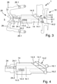
Fig. 1 im ausgeschlossenen blockierten Zustand, - Fig. 3
- eine schematische Darstellung der erfindungsgemäßen Verriegelungsanordnung aus
Fig. 1 ohne Gehäuse und Schlosskulisse im ausgeschlossenen blockierten Zustand vor einer Betätigung eines Entriegelungselements, - Fig. 4
- eine schematische Darstellung des ersten und zweiten Betätigungselements und des Schlossriegels der erfindungsgemäßen Verriegelungsanordnung aus
Fig. 1 im ausgeschlossenen blockierten Zustand vor der Betätigung des Entriegelungselements, - Fig. 5
- eine schematische Darstellung der erfindungsgemäßen Verriegelungsanordnung aus
Fig. 1 ohne Gehäuse und Schlosskulisse im ausgeschlossenen Zustand mit aufgehobener Blockierung, - Fig. 6
- eine schematische Darstellung des ersten und zweiten Betätigungselements und des Schlossriegels der erfindungsgemäßen Verriegelungsanordnung aus
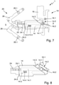
Fig. 1 im ausgeschlossenen Zustand mit aufgehobener Blockierung, - Fig. 7
- eine schematische Darstellung der erfindungsgemäßen Verriegelungsanordnung aus
Fig. 1 ohne Gehäuse und Schlosskulisse beim Übergang vom ausgeschlossenen Zustand zum eingeschlossenen Zustand, - Fig. 8
- eine schematische Darstellung des ersten und zweiten Betätigungselements und des Schlossriegels der erfindungsgemäßen Verriegelungsanordnung aus
Fig. 1 beim Übergang vom ausgeschlossenen Zustand zum eingeschlossenen Zustand, - Fig. 9
- eine schematische Darstellung der erfindungsgemäßen Verriegelungsanordnung aus
Fig. 1 ohne Gehäuse und Schlosskulisse im eingeschlossenen Zustand, - Fig. 10
- eine schematische Darstellung des ersten und zweiten Betätigungselements und des Schlossriegels der erfindungsgemäßen Verriegelungsanordnung aus
Fig. 1 im eingeschlossenen Zustand, - Fig. 11
- eine schematische Darstellung eines Beispiels einer nicht erfindungsgemäßen Verriegelungsanordnung ohne Gehäuse und Schlosskulisse im ausgeschlossenen blockierten Zustand,
- Fig. 12
- eine schematische Darstellung der nicht erfindungsgemäßen Verriegelungsanordnung aus
Fig. 11 ohne Gehäuse und Schlosskulisse im ausgeschlossenen blockierten Zustand vor einer Betätigung eines Entriegelungselements, - Fig. 13
- eine schematische Darstellung der nicht erfindungsgemäßen Verriegelungsanordnung aus
Fig. 11 ohne Gehäuse und Schlosskulisse im ausgeschlossenen Zustand mit aufgehobener Blockierung, und - Fig. 14
- eine schematische Darstellung der nicht erfindungsgemäßen Verriegelungsanordnung aus
Fig. 11 ohne Gehäuse und Schlosskulisse im eingeschlossenen Zustand.
- 1
- a schematic representation of a section of a double-leaf door with an embodiment of a locking arrangement according to the invention in the locked blocked state,
- 2
- a schematic representation of a first and second actuating element and a lock bolt of the locking arrangement according to the
invention 1 in the locked blocked state, - 3
- a schematic representation of the locking arrangement according to the
invention 1 without housing and lock link in the locked blocked state prior to actuation of an unlocking element, - 4
- a schematic representation of the first and second actuating element and the lock bolt of the locking arrangement according to the
invention 1 in the locked locked state before actuation of the unlocking element, - figure 5
- a schematic representation of the locking arrangement according to the
invention 1 without housing and lock gate in the locked state with the blocking removed, - 6
- a schematic representation of the first and second actuating element and the lock bolt of the locking arrangement according to the
invention 1 in the locked state with the block removed, - 7
- a schematic representation of the locking arrangement according to the
invention 1 without housing and lock gate during the transition from the locked state to the locked state, - 8
- a schematic representation of the first and second actuating element and the lock bolt of the locking arrangement according to the
invention 1 in the transition from the excluded state to the enclosed state, - 9
- a schematic representation of the locking arrangement according to the
invention 1 without housing and lock gate when locked, - 10
- a schematic representation of the first and second actuating element and the lock bolt of the locking arrangement according to the
invention 1 in the locked state, - 11
- a schematic representation of an example of a locking arrangement not according to the invention without a housing and lock link in the locked blocked state,
- 12
- a schematic representation of the locking arrangement not according to the invention
11 without housing and lock link in the locked blocked state prior to actuation of an unlocking element, - 13
- a schematic representation of the locking arrangement not according to the invention
11 without housing and lock link in locked state with unblocked, and - 14
- a schematic representation of the locking arrangement not according to the invention
11 without housing and lock gate when locked.
Wie aus
Erfindungsgemäß ist das Entriegelungselement 14.1 unabhängig vom Schließzustand des Schlossriegels 14 in Richtung Gegenkasten 20 vollständig in den Schlossriegel 14 eingebettet, wobei durch die Betätigung des Gegenkastens 20 zur Ausführung der Panikfunktion ein im Gegenkasten 20 angeordnetes zweites Betätigungselement 24.1, 24.1A das Entriegelungselement 14.1 in Richtung Blockierung bewegt und die Blockierung des Schlossriegels 14 aufhebt.According to the invention, the unlocking element 14.1 is completely embedded in the
Wie aus
Wie aus
Wie aus
Wie aus
Selbstverständlich kann der Fachmann auch andere geeignete Ausführungsformen für das erste Betätigungselement 24 und das zweite Betätigungselement 24.1 einsetzen.Of course, those skilled in the art can also use other suitable embodiments for the
Wie aus
Wie aus
Wie aus
Wie aus
Wie aus
Wie aus
Durch Drehen des Schwenkhebels 26A um die Schwenkachse 26.1A ist ein Ende des Schwenkhebels mit dem ersten Betätigungselement 24A und dem zweiten Betätigungselement 24.1A und einem korrespondierenden Anlageabschnitt 24.2A zwischen einer Ausgangslage und einer Endlage verschwenkbar. Das andere Ende des Schwenkhebels 26A ist mit dem nicht näher dargestellten Drücker und/oder der nicht näher dargestellten Panikstange des Standflügels 5 gekoppelt. Zudem ragt das als Betätigungsnase ausgeführte zweite Betätigungselement 24.1A bis zum Erreichen der Endlage in Richtung Schlossriegel 14 über den Anlageabschnitt 24.2A des ersten Betätigungselements 24A hinaus. Daher kann das zweite Betätigungselement 24.1A analog zum Ausführungsbeispiel vor dem Auftreffen des Anlageabschnitts 24.2A des ersten Betätigungselements 24 auf dem Schlossriegel 14 über eine Öffnung im Schlossriegel 14 auf das Entriegelungselement 14.1 wirken und die Blockierung des Schlossriegels 14 aufheben. Das zweite Betätigungselement 24.1A wirkt analog zum Ausführungsbeispiel gegen die Kraft der Rückstellfeder 14.4 auf den L-förmigen Endbereich 14.5 des Entriegelungselements 14.1.By rotating the pivoted
Wie aus
Wie aus
Wie aus
Wie aus
Ausführungsformen der erfindungsgemäßen Verriegelungsanordnung für eine zweiflügelige Tür stellen bei gleicher Panikfunktionalität in vorteilhafter Weise einen verbesserten Aufbruch- und/oder Einbruchschutz zur Verfügung.Embodiments of the locking arrangement according to the invention for a double-leaf door advantageously provide improved protection against forced entry and/or burglary with the same panic functionality.
- 1, 1A1, 1A
- Verriegelungsanordnunglocking arrangement
- 33
- Gangflügelactive leaf
- 55
- Standflügelinactive leaf
- 7, 97, 9
- Kreuzfallecross trap
- 1010
- Schlosskastenlock box
- 1212
- Gehäusehousing
- 1414
- Schlossriegellock bolt
- 14.114.1
- Entriegelungselementunlocking element
- 14.214.2
- Schrägeoblique
- 14.314.3
- Konturcontour
- 14.414.4
- Rückstellfederreturn spring
- 14.514.5
- Endbereichend area
- 1616
- Schlosskulissecastle backdrop
- 16.116.1
- Blockierelementblocking element
- 16.216.2
- Führungselementguide element
- 2020
- Gegenkastencounter box
- 2222
- Gehäusehousing
- 22.122.1
- Schließplattelocking plate
- 24, 24A24, 24A
- erstes Betätigungselementfirst actuator
- 24.1, 24.1A24.1, 24.1A
- zweites Betätigungselementsecond actuator
- 24.2, 24.2A24.2, 24.2A
- Anlageabschnittinvestment section
- 26, 26A26, 26A
- Schwenkhebelswing lever
- 26.1, 26.1A26.1, 26.1A
- Schwenkachsepivot axis
Claims (10)
- Locking arrangement (1) for a double-leaf door (active leaf 3, inactive leaf 5), comprising a lock case (10) having a lock bolt (14) and a blocking means, which secures the lock bolt (14) in an extended state against transfer into a retracted state, and also comprising a box keep (20) having a striker plate (22.1), in which the lock bolt (14) in the extended state engages, at least to some extent, wherein, by actuation of the box keep (20) for the purpose of performing a panic function, an unlocking element (14.1), which is guided in the lock bolt (14), disengages the blocking means of the lock bolt (14) and a first actuating element (24) transfers the lock bolt (14) from the extended state into the retracted state, in which the lock bolt (14) releases the striker plate (22.1), and, regardless of the locking state of the lock bolt (14) in the direction of the box keep (20), the unlocking element (14.1) is fully embedded in the lock bolt (14), wherein, by means of the actuation of the box keep (20) for the purpose of performing the panic function, a second actuating element (24.1) arranged in the box keep (20) moves the unlocking element (14.1) in the direction of the blocking means and disengages the blocking means of the lock bolt (14),
characterized
in that the second actuating element (24.1) is guided in an axially movable manner in the first actuating element (24), wherein the first actuating element (24) is movable between a starting position and an end position, wherein the second actuating element (24.1) until it reaches the end position projects in the direction of the lock bolt (14) beyond the first actuating element (24) and, before the first actuating element (24) strikes against the lock bolt (14), acts on the unlocking element (14.1) via an opening in the lock bolt (14). - Locking arrangement according to Claim 1, characterized
in that the blocking means is designed as a blocking element (16.1) which is fixedly connected to a movable lock slot (16) and, in the extended state of the lock bolt (14), forms a stop for the lock bolt (14). - Locking arrangement according to Claim 2, characterized
in that the unlocking element (14.1) is designed with an actuating slope which lifts the blocking element (16.1) onto an oblique surface (14.2) of the lock bolt (14). - Locking arrangement according to Claim 2 or 3, characterized
in that the lock slot (16) has a guide element (16.2) which, during the transfer of the lock bolt (14) into the retracted state, lies against a contour (16.3) of the lock bolt (14) and moves the lock slot (16) perpendicular to the lock bolt (14) as far as a stop. - Locking arrangement according to Claim 1, characterized
in that the first actuating element (24) upon reaching its end position completely receives the second actuating element (24.1), wherein the end position of the first actuating element (24) corresponds to the retracted state of the lock bolt (14) . - Locking arrangement according to Claim 1 or 5, characterized
in that the first actuating element (24) is designed as a slider and the second actuating element (24.1) is designed as an actuating pin. - Double-leaf door with an active leaf (3) and an inactive leaf (5), and with a locking arrangement (1) which comprises a lock case (10) having a lock bolt (14) and a blocking means, which secures the lock bolt (14) in an extended state against transfer into a retracted state, and also comprising a box keep (20) having a striker plate (22.1), in which the lock bolt (14) in the extended state engages, at least to some extent, wherein, by actuation of the box keep (20) for the purpose of performing a panic function, an unlocking element (14.1), which is guided in the lock bolt (14), disengages the blocking means of the lock bolt (14) and a first actuating element (24) transfers the lock bolt (14) from the extended state into the retracted state, in which the lock bolt (14) releases the striker plate (22.1) and the door is unlocked, characterized
in that the locking arrangement (1) is designed according to at least one of Claims 1 to 6. - Double-leaf door according to Claim 7, characterized
in that the lock case (10) with lock bolt (14) and blocking means, which is in the form of a blocking element (16.1), is arranged on the active leaf (3) and the box keep (20) with striker plate (5) is arranged on the inactive leaf (5). - Double-leaf door according to Claim 8, characterized
in that a handle and/or a panic bar of the inactive leaf (5), for the purpose of performing the panic function, act on the first actuating element (24) via at least one pivot lever (26) and actuate the box keep (20), which then actuates the lock case (10), wherein a handle and/or a panic bar of the active leaf (3), for the purpose of performing the panic function, act on the blocking element (16.1) and the lock bolt (14) and actuate the lock case (10) directly. - Double-leaf door according to Claim 9, characterized
in that two pivot levers (26) act on the first actuating element (24), which is in the form of a slider, and actuate the box keep (20).
Applications Claiming Priority (1)
| Application Number | Priority Date | Filing Date | Title |
|---|---|---|---|
| DE102016225000.0A DE102016225000B4 (en) | 2016-12-14 | 2016-12-14 | LOCKING ARRANGEMENT FOR A DOUBLE LEAF DOOR |
Publications (2)
| Publication Number | Publication Date |
|---|---|
| EP3336289A1 EP3336289A1 (en) | 2018-06-20 |
| EP3336289B1 true EP3336289B1 (en) | 2022-02-16 |
Family
ID=60327156
Family Applications (1)
| Application Number | Title | Priority Date | Filing Date |
|---|---|---|---|
| EP17201648.7A Active EP3336289B1 (en) | 2016-12-14 | 2017-11-14 | Closure assembly for a double-leaf door |
Country Status (3)
| Country | Link |
|---|---|
| EP (1) | EP3336289B1 (en) |
| CN (1) | CN108222700B (en) |
| DE (1) | DE102016225000B4 (en) |
Family Cites Families (10)
| Publication number | Priority date | Publication date | Assignee | Title |
|---|---|---|---|---|
| DE1703470U (en) | 1955-05-05 | 1955-07-28 | Schubert & Salzer Maschinen | BRAKE DEVICE FOR MOUNTING SPINDLES. |
| DE1703470B1 (en) * | 1968-05-25 | 1972-02-03 | Eaton Gmbh | Double-acting panic lock for double-leaf doors |
| DE19740448C1 (en) | 1997-09-15 | 1999-01-14 | Schlechtendahl & Soehne Wilh | Panic lock for building door |
| DE102004003168B4 (en) * | 2004-01-21 | 2008-10-23 | Wilka Schließtechnik GmbH | Dead bolt lock for double-leaf doors with panic function |
| JP4410777B2 (en) * | 2006-06-15 | 2010-02-03 | 株式会社ベスト | Emergency unlocking structure of non-display type lock |
| DE102009003860B4 (en) | 2009-04-30 | 2015-10-22 | Wilka Schließtechnik GmbH | Panic lock with lever that can be lifted by actuating one of the bartacks |
| DE102011000553A1 (en) * | 2011-02-08 | 2012-08-09 | Dorma Gmbh & Co Kg | Lock system for a double-leaf door system with panic function |
| DE202013000920U1 (en) * | 2013-01-30 | 2013-02-26 | Kfv Karl Fliether Gmbh & Co. Kg | panic lock |
| DE102014215174A1 (en) * | 2014-08-01 | 2016-02-04 | Aug. Winkhaus Gmbh & Co. Kg | Espagnolette |
| EP3259422A1 (en) * | 2015-02-20 | 2017-12-27 | Cisa S.p.a. | Lock for double leaf door |
-
2016
- 2016-12-14 DE DE102016225000.0A patent/DE102016225000B4/en not_active Withdrawn - After Issue
-
2017
- 2017-11-14 EP EP17201648.7A patent/EP3336289B1/en active Active
- 2017-12-14 CN CN201711333471.4A patent/CN108222700B/en active Active
Non-Patent Citations (1)
| Title |
|---|
| None * |
Also Published As
| Publication number | Publication date |
|---|---|
| CN108222700B (en) | 2020-02-21 |
| EP3336289A1 (en) | 2018-06-20 |
| DE102016225000A1 (en) | 2018-06-14 |
| DE102016225000B4 (en) | 2021-08-19 |
| CN108222700A (en) | 2018-06-29 |
Similar Documents
| Publication | Publication Date | Title |
|---|---|---|
| EP1932989B1 (en) | Locking device for doors, windows or similar, in particular an espagnolette lock with panic function and multi-point locking | |
| DE19701761C1 (en) | Self-locking lock for door | |
| EP2673435B1 (en) | Locking system for a two-leaf door assembly with panic function | |
| EP1970507B1 (en) | Anti panic lock | |
| EP3372757B1 (en) | Locking unit for a locking system of a door | |
| EP1431481B1 (en) | Lock | |
| EP0816603B1 (en) | Self-locking antipanic lock | |
| EP1617019B1 (en) | Electromechanical door lock | |
| EP2820208B1 (en) | Lock | |
| EP3426867B1 (en) | Lock | |
| EP1624140B1 (en) | Locking device | |
| EP3336287B1 (en) | Closure assembly for a double-leaf door | |
| EP3336289B1 (en) | Closure assembly for a double-leaf door | |
| EP3406828A1 (en) | Lock for a wing | |
| DE102018203293B4 (en) | Lock for a grand piano | |
| EP3628801B1 (en) | Lock device for a door and a method for opening a door | |
| EP0439478B1 (en) | Automatic lock | |
| EP3216952B1 (en) | Locking device | |
| EP3336288B1 (en) | Closure assembly for a double-leaf door | |
| AT407066B (en) | DOOR CLOSURE | |
| EP3543437B1 (en) | Lock assembly with a lock for a corridor winged door | |
| EP2708686B1 (en) | Panic lock and method for operating a panic lock | |
| DE4423163A1 (en) | Door mortice lock with spring=bolt | |
| DE102017000346A1 (en) | lock | |
| DE19834343A1 (en) | Window or door lock has a holder to retain the latch when the window/door is open and it is released by a control when the window/door is closed |
Legal Events
| Date | Code | Title | Description |
|---|---|---|---|
| PUAI | Public reference made under article 153(3) epc to a published international application that has entered the european phase |
Free format text: ORIGINAL CODE: 0009012 |
|
| STAA | Information on the status of an ep patent application or granted ep patent |
Free format text: STATUS: THE APPLICATION HAS BEEN PUBLISHED |
|
| AK | Designated contracting states |
Kind code of ref document: A1 Designated state(s): AL AT BE BG CH CY CZ DE DK EE ES FI FR GB GR HR HU IE IS IT LI LT LU LV MC MK MT NL NO PL PT RO RS SE SI SK SM TR |
|
| AX | Request for extension of the european patent |
Extension state: BA ME |
|
| STAA | Information on the status of an ep patent application or granted ep patent |
Free format text: STATUS: REQUEST FOR EXAMINATION WAS MADE |
|
| 17P | Request for examination filed |
Effective date: 20181206 |
|
| RBV | Designated contracting states (corrected) |
Designated state(s): AL AT BE BG CH CY CZ DE DK EE ES FI FR GB GR HR HU IE IS IT LI LT LU LV MC MK MT NL NO PL PT RO RS SE SI SK SM TR |
|
| STAA | Information on the status of an ep patent application or granted ep patent |
Free format text: STATUS: EXAMINATION IS IN PROGRESS |
|
| 17Q | First examination report despatched |
Effective date: 20190627 |
|
| STAA | Information on the status of an ep patent application or granted ep patent |
Free format text: STATUS: EXAMINATION IS IN PROGRESS |
|
| GRAP | Despatch of communication of intention to grant a patent |
Free format text: ORIGINAL CODE: EPIDOSNIGR1 |
|
| STAA | Information on the status of an ep patent application or granted ep patent |
Free format text: STATUS: GRANT OF PATENT IS INTENDED |
|
| INTG | Intention to grant announced |
Effective date: 20211018 |
|
| GRAS | Grant fee paid |
Free format text: ORIGINAL CODE: EPIDOSNIGR3 |
|
| GRAA | (expected) grant |
Free format text: ORIGINAL CODE: 0009210 |
|
| STAA | Information on the status of an ep patent application or granted ep patent |
Free format text: STATUS: THE PATENT HAS BEEN GRANTED |
|
| AK | Designated contracting states |
Kind code of ref document: B1 Designated state(s): AL AT BE BG CH CY CZ DE DK EE ES FI FR GB GR HR HU IE IS IT LI LT LU LV MC MK MT NL NO PL PT RO RS SE SI SK SM TR |
|
| REG | Reference to a national code |
Ref country code: GB Ref legal event code: FG4D Free format text: NOT ENGLISH |
|
| REG | Reference to a national code |
Ref country code: CH Ref legal event code: EP |
|
| REG | Reference to a national code |
Ref country code: DE Ref legal event code: R096 Ref document number: 502017012597 Country of ref document: DE |
|
| REG | Reference to a national code |
Ref country code: AT Ref legal event code: REF Ref document number: 1468977 Country of ref document: AT Kind code of ref document: T Effective date: 20220315 |
|
| REG | Reference to a national code |
Ref country code: IE Ref legal event code: FG4D Free format text: LANGUAGE OF EP DOCUMENT: GERMAN |
|
| REG | Reference to a national code |
Ref country code: LT Ref legal event code: MG9D |
|
| REG | Reference to a national code |
Ref country code: NL Ref legal event code: MP Effective date: 20220216 |
|
| PG25 | Lapsed in a contracting state [announced via postgrant information from national office to epo] |
Ref country code: SE Free format text: LAPSE BECAUSE OF FAILURE TO SUBMIT A TRANSLATION OF THE DESCRIPTION OR TO PAY THE FEE WITHIN THE PRESCRIBED TIME-LIMIT Effective date: 20220216 Ref country code: RS Free format text: LAPSE BECAUSE OF FAILURE TO SUBMIT A TRANSLATION OF THE DESCRIPTION OR TO PAY THE FEE WITHIN THE PRESCRIBED TIME-LIMIT Effective date: 20220216 Ref country code: PT Free format text: LAPSE BECAUSE OF FAILURE TO SUBMIT A TRANSLATION OF THE DESCRIPTION OR TO PAY THE FEE WITHIN THE PRESCRIBED TIME-LIMIT Effective date: 20220616 Ref country code: NO Free format text: LAPSE BECAUSE OF FAILURE TO SUBMIT A TRANSLATION OF THE DESCRIPTION OR TO PAY THE FEE WITHIN THE PRESCRIBED TIME-LIMIT Effective date: 20220516 Ref country code: NL Free format text: LAPSE BECAUSE OF FAILURE TO SUBMIT A TRANSLATION OF THE DESCRIPTION OR TO PAY THE FEE WITHIN THE PRESCRIBED TIME-LIMIT Effective date: 20220216 Ref country code: LT Free format text: LAPSE BECAUSE OF FAILURE TO SUBMIT A TRANSLATION OF THE DESCRIPTION OR TO PAY THE FEE WITHIN THE PRESCRIBED TIME-LIMIT Effective date: 20220216 Ref country code: HR Free format text: LAPSE BECAUSE OF FAILURE TO SUBMIT A TRANSLATION OF THE DESCRIPTION OR TO PAY THE FEE WITHIN THE PRESCRIBED TIME-LIMIT Effective date: 20220216 Ref country code: ES Free format text: LAPSE BECAUSE OF FAILURE TO SUBMIT A TRANSLATION OF THE DESCRIPTION OR TO PAY THE FEE WITHIN THE PRESCRIBED TIME-LIMIT Effective date: 20220216 Ref country code: BG Free format text: LAPSE BECAUSE OF FAILURE TO SUBMIT A TRANSLATION OF THE DESCRIPTION OR TO PAY THE FEE WITHIN THE PRESCRIBED TIME-LIMIT Effective date: 20220516 |
|
| PG25 | Lapsed in a contracting state [announced via postgrant information from national office to epo] |
Ref country code: PL Free format text: LAPSE BECAUSE OF FAILURE TO SUBMIT A TRANSLATION OF THE DESCRIPTION OR TO PAY THE FEE WITHIN THE PRESCRIBED TIME-LIMIT Effective date: 20220216 Ref country code: LV Free format text: LAPSE BECAUSE OF FAILURE TO SUBMIT A TRANSLATION OF THE DESCRIPTION OR TO PAY THE FEE WITHIN THE PRESCRIBED TIME-LIMIT Effective date: 20220216 Ref country code: GR Free format text: LAPSE BECAUSE OF FAILURE TO SUBMIT A TRANSLATION OF THE DESCRIPTION OR TO PAY THE FEE WITHIN THE PRESCRIBED TIME-LIMIT Effective date: 20220517 Ref country code: FI Free format text: LAPSE BECAUSE OF FAILURE TO SUBMIT A TRANSLATION OF THE DESCRIPTION OR TO PAY THE FEE WITHIN THE PRESCRIBED TIME-LIMIT Effective date: 20220216 |
|
| PG25 | Lapsed in a contracting state [announced via postgrant information from national office to epo] |
Ref country code: IS Free format text: LAPSE BECAUSE OF FAILURE TO SUBMIT A TRANSLATION OF THE DESCRIPTION OR TO PAY THE FEE WITHIN THE PRESCRIBED TIME-LIMIT Effective date: 20220617 |
|
| PG25 | Lapsed in a contracting state [announced via postgrant information from national office to epo] |
Ref country code: SM Free format text: LAPSE BECAUSE OF FAILURE TO SUBMIT A TRANSLATION OF THE DESCRIPTION OR TO PAY THE FEE WITHIN THE PRESCRIBED TIME-LIMIT Effective date: 20220216 Ref country code: SK Free format text: LAPSE BECAUSE OF FAILURE TO SUBMIT A TRANSLATION OF THE DESCRIPTION OR TO PAY THE FEE WITHIN THE PRESCRIBED TIME-LIMIT Effective date: 20220216 Ref country code: RO Free format text: LAPSE BECAUSE OF FAILURE TO SUBMIT A TRANSLATION OF THE DESCRIPTION OR TO PAY THE FEE WITHIN THE PRESCRIBED TIME-LIMIT Effective date: 20220216 Ref country code: EE Free format text: LAPSE BECAUSE OF FAILURE TO SUBMIT A TRANSLATION OF THE DESCRIPTION OR TO PAY THE FEE WITHIN THE PRESCRIBED TIME-LIMIT Effective date: 20220216 Ref country code: DK Free format text: LAPSE BECAUSE OF FAILURE TO SUBMIT A TRANSLATION OF THE DESCRIPTION OR TO PAY THE FEE WITHIN THE PRESCRIBED TIME-LIMIT Effective date: 20220216 Ref country code: CZ Free format text: LAPSE BECAUSE OF FAILURE TO SUBMIT A TRANSLATION OF THE DESCRIPTION OR TO PAY THE FEE WITHIN THE PRESCRIBED TIME-LIMIT Effective date: 20220216 |
|
| REG | Reference to a national code |
Ref country code: DE Ref legal event code: R097 Ref document number: 502017012597 Country of ref document: DE |
|
| PG25 | Lapsed in a contracting state [announced via postgrant information from national office to epo] |
Ref country code: AL Free format text: LAPSE BECAUSE OF FAILURE TO SUBMIT A TRANSLATION OF THE DESCRIPTION OR TO PAY THE FEE WITHIN THE PRESCRIBED TIME-LIMIT Effective date: 20220216 |
|
| PLBE | No opposition filed within time limit |
Free format text: ORIGINAL CODE: 0009261 |
|
| STAA | Information on the status of an ep patent application or granted ep patent |
Free format text: STATUS: NO OPPOSITION FILED WITHIN TIME LIMIT |
|
| 26N | No opposition filed |
Effective date: 20221117 |
|
| PG25 | Lapsed in a contracting state [announced via postgrant information from national office to epo] |
Ref country code: SI Free format text: LAPSE BECAUSE OF FAILURE TO SUBMIT A TRANSLATION OF THE DESCRIPTION OR TO PAY THE FEE WITHIN THE PRESCRIBED TIME-LIMIT Effective date: 20220216 |
|
| P01 | Opt-out of the competence of the unified patent court (upc) registered |
Effective date: 20230510 |
|
| PG25 | Lapsed in a contracting state [announced via postgrant information from national office to epo] |
Ref country code: MC Free format text: LAPSE BECAUSE OF FAILURE TO SUBMIT A TRANSLATION OF THE DESCRIPTION OR TO PAY THE FEE WITHIN THE PRESCRIBED TIME-LIMIT Effective date: 20220216 |
|
| REG | Reference to a national code |
Ref country code: CH Ref legal event code: PL |
|
| GBPC | Gb: european patent ceased through non-payment of renewal fee |
Effective date: 20221114 |
|
| REG | Reference to a national code |
Ref country code: BE Ref legal event code: MM Effective date: 20221130 |
|
| PG25 | Lapsed in a contracting state [announced via postgrant information from national office to epo] |
Ref country code: LI Free format text: LAPSE BECAUSE OF NON-PAYMENT OF DUE FEES Effective date: 20221130 Ref country code: IT Free format text: LAPSE BECAUSE OF FAILURE TO SUBMIT A TRANSLATION OF THE DESCRIPTION OR TO PAY THE FEE WITHIN THE PRESCRIBED TIME-LIMIT Effective date: 20220216 Ref country code: CH Free format text: LAPSE BECAUSE OF NON-PAYMENT OF DUE FEES Effective date: 20221130 |
|
| PG25 | Lapsed in a contracting state [announced via postgrant information from national office to epo] |
Ref country code: LU Free format text: LAPSE BECAUSE OF NON-PAYMENT OF DUE FEES Effective date: 20221114 |
|
| PG25 | Lapsed in a contracting state [announced via postgrant information from national office to epo] |
Ref country code: IE Free format text: LAPSE BECAUSE OF NON-PAYMENT OF DUE FEES Effective date: 20221114 Ref country code: GB Free format text: LAPSE BECAUSE OF NON-PAYMENT OF DUE FEES Effective date: 20221114 |
|
| PG25 | Lapsed in a contracting state [announced via postgrant information from national office to epo] |
Ref country code: FR Free format text: LAPSE BECAUSE OF NON-PAYMENT OF DUE FEES Effective date: 20221130 Ref country code: BE Free format text: LAPSE BECAUSE OF NON-PAYMENT OF DUE FEES Effective date: 20221130 |
|
| REG | Reference to a national code |
Ref country code: AT Ref legal event code: MM01 Ref document number: 1468977 Country of ref document: AT Kind code of ref document: T Effective date: 20221114 |
|
| PG25 | Lapsed in a contracting state [announced via postgrant information from national office to epo] |
Ref country code: AT Free format text: LAPSE BECAUSE OF NON-PAYMENT OF DUE FEES Effective date: 20221114 |
|
| PGFP | Annual fee paid to national office [announced via postgrant information from national office to epo] |
Ref country code: DE Payment date: 20231130 Year of fee payment: 7 |
|
| PG25 | Lapsed in a contracting state [announced via postgrant information from national office to epo] |
Ref country code: HU Free format text: LAPSE BECAUSE OF FAILURE TO SUBMIT A TRANSLATION OF THE DESCRIPTION OR TO PAY THE FEE WITHIN THE PRESCRIBED TIME-LIMIT; INVALID AB INITIO Effective date: 20171114 |