EP3335995A1 - Hybrid-elektrisches antriebssystem - Google Patents
Hybrid-elektrisches antriebssystem Download PDFInfo
- Publication number
- EP3335995A1 EP3335995A1 EP17206819.9A EP17206819A EP3335995A1 EP 3335995 A1 EP3335995 A1 EP 3335995A1 EP 17206819 A EP17206819 A EP 17206819A EP 3335995 A1 EP3335995 A1 EP 3335995A1
- Authority
- EP
- European Patent Office
- Prior art keywords
- driveshaft
- propulsor
- propulsion system
- output shaft
- electric machine
- Prior art date
- Legal status (The legal status is an assumption and is not a legal conclusion. Google has not performed a legal analysis and makes no representation as to the accuracy of the status listed.)
- Granted
Links
- 238000002485 combustion reaction Methods 0.000 claims abstract description 40
- 238000000034 method Methods 0.000 claims description 26
- 239000007789 gas Substances 0.000 description 37
- 239000003570 air Substances 0.000 description 10
- 239000000567 combustion gas Substances 0.000 description 8
- 230000007704 transition Effects 0.000 description 5
- 239000012530 fluid Substances 0.000 description 4
- 230000008878 coupling Effects 0.000 description 3
- 238000010168 coupling process Methods 0.000 description 3
- 238000005859 coupling reaction Methods 0.000 description 3
- 238000011144 upstream manufacturing Methods 0.000 description 3
- 238000004146 energy storage Methods 0.000 description 2
- 239000000446 fuel Substances 0.000 description 2
- 239000012080 ambient air Substances 0.000 description 1
- 238000010586 diagram Methods 0.000 description 1
- 230000004907 flux Effects 0.000 description 1
- 230000003137 locomotive effect Effects 0.000 description 1
- 238000005461 lubrication Methods 0.000 description 1
- 230000037361 pathway Effects 0.000 description 1
- 239000013589 supplement Substances 0.000 description 1
- 230000000153 supplemental effect Effects 0.000 description 1
- 230000001502 supplementing effect Effects 0.000 description 1
Images


Classifications
-
- B—PERFORMING OPERATIONS; TRANSPORTING
- B64—AIRCRAFT; AVIATION; COSMONAUTICS
- B64D—EQUIPMENT FOR FITTING IN OR TO AIRCRAFT; FLIGHT SUITS; PARACHUTES; ARRANGEMENTS OR MOUNTING OF POWER PLANTS OR PROPULSION TRANSMISSIONS IN AIRCRAFT
- B64D27/00—Arrangement or mounting of power plant in aircraft; Aircraft characterised thereby
- B64D27/02—Aircraft characterised by the type or position of power plant
- B64D27/24—Aircraft characterised by the type or position of power plant using steam, electricity, or spring force
-
- F—MECHANICAL ENGINEERING; LIGHTING; HEATING; WEAPONS; BLASTING
- F01—MACHINES OR ENGINES IN GENERAL; ENGINE PLANTS IN GENERAL; STEAM ENGINES
- F01D—NON-POSITIVE DISPLACEMENT MACHINES OR ENGINES, e.g. STEAM TURBINES
- F01D15/00—Adaptations of machines or engines for special use; Combinations of engines with devices driven thereby
- F01D15/10—Adaptations for driving, or combinations with, electric generators
-
- B—PERFORMING OPERATIONS; TRANSPORTING
- B63—SHIPS OR OTHER WATERBORNE VESSELS; RELATED EQUIPMENT
- B63H—MARINE PROPULSION OR STEERING
- B63H21/00—Use of propulsion power plant or units on vessels
- B63H21/20—Use of propulsion power plant or units on vessels the vessels being powered by combinations of different types of propulsion units
-
- B—PERFORMING OPERATIONS; TRANSPORTING
- B64—AIRCRAFT; AVIATION; COSMONAUTICS
- B64D—EQUIPMENT FOR FITTING IN OR TO AIRCRAFT; FLIGHT SUITS; PARACHUTES; ARRANGEMENTS OR MOUNTING OF POWER PLANTS OR PROPULSION TRANSMISSIONS IN AIRCRAFT
- B64D27/00—Arrangement or mounting of power plant in aircraft; Aircraft characterised thereby
- B64D27/02—Aircraft characterised by the type or position of power plant
-
- B64D27/026—
-
- F—MECHANICAL ENGINEERING; LIGHTING; HEATING; WEAPONS; BLASTING
- F02—COMBUSTION ENGINES; HOT-GAS OR COMBUSTION-PRODUCT ENGINE PLANTS
- F02C—GAS-TURBINE PLANTS; AIR INTAKES FOR JET-PROPULSION PLANTS; CONTROLLING FUEL SUPPLY IN AIR-BREATHING JET-PROPULSION PLANTS
- F02C7/00—Features, components parts, details or accessories, not provided for in, or of interest apart form groups F02C1/00 - F02C6/00; Air intakes for jet-propulsion plants
- F02C7/36—Power transmission arrangements between the different shafts of the gas turbine plant, or between the gas-turbine plant and the power user
-
- F—MECHANICAL ENGINEERING; LIGHTING; HEATING; WEAPONS; BLASTING
- F16—ENGINEERING ELEMENTS AND UNITS; GENERAL MEASURES FOR PRODUCING AND MAINTAINING EFFECTIVE FUNCTIONING OF MACHINES OR INSTALLATIONS; THERMAL INSULATION IN GENERAL
- F16D—COUPLINGS FOR TRANSMITTING ROTATION; CLUTCHES; BRAKES
- F16D41/00—Freewheels or freewheel clutches
- F16D41/06—Freewheels or freewheel clutches with intermediate wedging coupling members between an inner and an outer surface
- F16D41/069—Freewheels or freewheel clutches with intermediate wedging coupling members between an inner and an outer surface the intermediate members wedging by pivoting or rocking, e.g. sprags
-
- F—MECHANICAL ENGINEERING; LIGHTING; HEATING; WEAPONS; BLASTING
- F16—ENGINEERING ELEMENTS AND UNITS; GENERAL MEASURES FOR PRODUCING AND MAINTAINING EFFECTIVE FUNCTIONING OF MACHINES OR INSTALLATIONS; THERMAL INSULATION IN GENERAL
- F16D—COUPLINGS FOR TRANSMITTING ROTATION; CLUTCHES; BRAKES
- F16D48/00—External control of clutches
- F16D48/06—Control by electric or electronic means, e.g. of fluid pressure
-
- B—PERFORMING OPERATIONS; TRANSPORTING
- B63—SHIPS OR OTHER WATERBORNE VESSELS; RELATED EQUIPMENT
- B63H—MARINE PROPULSION OR STEERING
- B63H21/00—Use of propulsion power plant or units on vessels
- B63H21/20—Use of propulsion power plant or units on vessels the vessels being powered by combinations of different types of propulsion units
- B63H2021/202—Use of propulsion power plant or units on vessels the vessels being powered by combinations of different types of propulsion units of hybrid electric type
- B63H2021/207—Use of propulsion power plant or units on vessels the vessels being powered by combinations of different types of propulsion units of hybrid electric type the second power unit being a gas turbine
-
- B—PERFORMING OPERATIONS; TRANSPORTING
- B64—AIRCRAFT; AVIATION; COSMONAUTICS
- B64D—EQUIPMENT FOR FITTING IN OR TO AIRCRAFT; FLIGHT SUITS; PARACHUTES; ARRANGEMENTS OR MOUNTING OF POWER PLANTS OR PROPULSION TRANSMISSIONS IN AIRCRAFT
- B64D27/00—Arrangement or mounting of power plant in aircraft; Aircraft characterised thereby
- B64D27/02—Aircraft characterised by the type or position of power plant
- B64D27/10—Aircraft characterised by the type or position of power plant of gas-turbine type
-
- B—PERFORMING OPERATIONS; TRANSPORTING
- B64—AIRCRAFT; AVIATION; COSMONAUTICS
- B64D—EQUIPMENT FOR FITTING IN OR TO AIRCRAFT; FLIGHT SUITS; PARACHUTES; ARRANGEMENTS OR MOUNTING OF POWER PLANTS OR PROPULSION TRANSMISSIONS IN AIRCRAFT
- B64D35/00—Transmitting power from power plant to propellers or rotors; Arrangements of transmissions
- B64D35/08—Transmitting power from power plant to propellers or rotors; Arrangements of transmissions characterised by the transmission being driven by a plurality of power plants
-
- F—MECHANICAL ENGINEERING; LIGHTING; HEATING; WEAPONS; BLASTING
- F05—INDEXING SCHEMES RELATING TO ENGINES OR PUMPS IN VARIOUS SUBCLASSES OF CLASSES F01-F04
- F05D—INDEXING SCHEME FOR ASPECTS RELATING TO NON-POSITIVE-DISPLACEMENT MACHINES OR ENGINES, GAS-TURBINES OR JET-PROPULSION PLANTS
- F05D2220/00—Application
- F05D2220/30—Application in turbines
- F05D2220/32—Application in turbines in gas turbines
-
- F—MECHANICAL ENGINEERING; LIGHTING; HEATING; WEAPONS; BLASTING
- F05—INDEXING SCHEMES RELATING TO ENGINES OR PUMPS IN VARIOUS SUBCLASSES OF CLASSES F01-F04
- F05D—INDEXING SCHEME FOR ASPECTS RELATING TO NON-POSITIVE-DISPLACEMENT MACHINES OR ENGINES, GAS-TURBINES OR JET-PROPULSION PLANTS
- F05D2220/00—Application
- F05D2220/70—Application in combination with
- F05D2220/76—Application in combination with an electrical generator
-
- F—MECHANICAL ENGINEERING; LIGHTING; HEATING; WEAPONS; BLASTING
- F05—INDEXING SCHEMES RELATING TO ENGINES OR PUMPS IN VARIOUS SUBCLASSES OF CLASSES F01-F04
- F05D—INDEXING SCHEME FOR ASPECTS RELATING TO NON-POSITIVE-DISPLACEMENT MACHINES OR ENGINES, GAS-TURBINES OR JET-PROPULSION PLANTS
- F05D2240/00—Components
- F05D2240/60—Shafts
-
- F—MECHANICAL ENGINEERING; LIGHTING; HEATING; WEAPONS; BLASTING
- F05—INDEXING SCHEMES RELATING TO ENGINES OR PUMPS IN VARIOUS SUBCLASSES OF CLASSES F01-F04
- F05D—INDEXING SCHEME FOR ASPECTS RELATING TO NON-POSITIVE-DISPLACEMENT MACHINES OR ENGINES, GAS-TURBINES OR JET-PROPULSION PLANTS
- F05D2260/00—Function
- F05D2260/40—Transmission of power
- F05D2260/402—Transmission of power through friction drives
- F05D2260/4023—Transmission of power through friction drives through a friction clutch
-
- F—MECHANICAL ENGINEERING; LIGHTING; HEATING; WEAPONS; BLASTING
- F16—ENGINEERING ELEMENTS AND UNITS; GENERAL MEASURES FOR PRODUCING AND MAINTAINING EFFECTIVE FUNCTIONING OF MACHINES OR INSTALLATIONS; THERMAL INSULATION IN GENERAL
- F16D—COUPLINGS FOR TRANSMITTING ROTATION; CLUTCHES; BRAKES
- F16D2500/00—External control of clutches by electric or electronic means
- F16D2500/10—System to be controlled
- F16D2500/104—Clutch
- F16D2500/10406—Clutch position
- F16D2500/10412—Transmission line of a vehicle
-
- F—MECHANICAL ENGINEERING; LIGHTING; HEATING; WEAPONS; BLASTING
- F16—ENGINEERING ELEMENTS AND UNITS; GENERAL MEASURES FOR PRODUCING AND MAINTAINING EFFECTIVE FUNCTIONING OF MACHINES OR INSTALLATIONS; THERMAL INSULATION IN GENERAL
- F16D—COUPLINGS FOR TRANSMITTING ROTATION; CLUTCHES; BRAKES
- F16D2500/00—External control of clutches by electric or electronic means
- F16D2500/10—System to be controlled
- F16D2500/104—Clutch
- F16D2500/10443—Clutch type
- F16D2500/10493—One way clutch
-
- F—MECHANICAL ENGINEERING; LIGHTING; HEATING; WEAPONS; BLASTING
- F16—ENGINEERING ELEMENTS AND UNITS; GENERAL MEASURES FOR PRODUCING AND MAINTAINING EFFECTIVE FUNCTIONING OF MACHINES OR INSTALLATIONS; THERMAL INSULATION IN GENERAL
- F16D—COUPLINGS FOR TRANSMITTING ROTATION; CLUTCHES; BRAKES
- F16D2500/00—External control of clutches by electric or electronic means
- F16D2500/30—Signal inputs
- F16D2500/306—Signal inputs from the engine
- F16D2500/3065—Torque of the engine
-
- Y—GENERAL TAGGING OF NEW TECHNOLOGICAL DEVELOPMENTS; GENERAL TAGGING OF CROSS-SECTIONAL TECHNOLOGIES SPANNING OVER SEVERAL SECTIONS OF THE IPC; TECHNICAL SUBJECTS COVERED BY FORMER USPC CROSS-REFERENCE ART COLLECTIONS [XRACs] AND DIGESTS
- Y02—TECHNOLOGIES OR APPLICATIONS FOR MITIGATION OR ADAPTATION AGAINST CLIMATE CHANGE
- Y02T—CLIMATE CHANGE MITIGATION TECHNOLOGIES RELATED TO TRANSPORTATION
- Y02T50/00—Aeronautics or air transport
- Y02T50/60—Efficient propulsion technologies, e.g. for aircraft
Definitions
- the present subject matter relates generally to a hybrid-electric propulsion system utilizing a gas turbine engine.
- a turbine engine of an exemplary gas turbine engine generally includes, in serial flow order, a compressor section, a combustion section, and a turbine section.
- ambient air is provided to an inlet of the compressor section where one or more axial compressors progressively compress the air until it reaches the combustion section.
- Fuel is mixed with the compressed air and burned within the combustion section to provide combustion gases.
- the combustion gases are routed from the combustion section to the turbine section.
- the flow of combustion gasses through the turbine section drives the turbine section.
- the turbine engine of the gas turbine engine may be used to drive, e.g., a propeller.
- a secondary power source may be used to supplement an amount of power provided to the propeller by the gas turbine engine, or alternatively, to substitute the power provided to the propeller by the gas turbine engine. With the latter case, complications may arise if the secondary power source additionally causes rotation of certain components of the gas turbine engine without the gas turbine engine operating.
- a propulsion system including a secondary power source capable of supplementing or substituting power provided by a gas turbine engine capable of overcoming the above obstacles would be particularly useful in the art.
- a propulsion system in one exemplary aspect of the present disclosure, includes a driveshaft, an electric machine coupled to the driveshaft, and a combustion engine having an output shaft.
- the propulsion system additionally includes a one-way clutch operable with at least one of the driveshaft and the output shaft of the combustion engine.
- the one-way clutch allows for a differential angular velocity of the driveshaft relative to the output shaft in a first circumferential direction and prevents a differential angular velocity of the driveshaft relative to the output shaft in a second circumferential direction.
- a method of operating a propulsion system includes a propulsor including a driveshaft, an electric machine coupled to the driveshaft, a combustion engine having an output shaft, and a one-way clutch operable with at least one of the driveshaft of the propulsor and the output shaft of the combustion engine.
- the method includes operating the propulsion system to power the propulsor at least in part with the combustion engine such that the one-way clutch couples the output shaft of the combustion engine to the driveshaft of the propulsor.
- the method also includes operating the propulsion system to power the propulsor at least in part with the electric machine such that the one-way clutch decouples the output shaft of the combustion engine from the driveshaft of the propulsor.
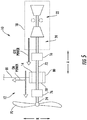
- FIG. 1 is a schematic view of a propulsion system 10 in accordance with an exemplary embodiment of the present disclosure.
- the propulsion system 10 generally includes a gas turbine engine (a schematic, cross-sectional view of which is provided in FIG. 1 ), a propulsor 12, an electric machine 14, and a one-way clutch 16.
- a gas turbine engine a schematic, cross-sectional view of which is provided in FIG. 1
- a propulsor 12 an electric machine
- a one-way clutch 16 a one-way clutch
- turboshaft engine 18 the gas turbine engine depicted is configured as a turboshaft engine, referred to herein as "turboshaft engine 18."
- turboshaft engine 18 may instead be configured in any other suitable manner.
- the turboshaft engine 18 may instead be configured as a turboprop engine, a turbofan engine, or any other suitable combustion engine (such as any other suitable gas turbine engine or, e.g., internal combustion engine).
- the turboshaft engine 18 defines an axial direction A (extending parallel to a longitudinal centerline 20 provided for reference), a radial direction R, and a circumferential direction C (i.e., a direction extending about the axial direction A; see FIG. 2 ).
- the turboshaft engine 18 includes a turbine engine 22 and an output shaft 24.
- the exemplary turbine engine 22 depicted generally includes a substantially tubular outer casing 26 that partially encloses an annular, radial inlet duct 28.
- the radial inlet duct 28 includes at least a portion extending generally along the radial direction R, and is further configured to turn a direction of an air flow therethrough, such that the resulting airflow is generally along the axial direction A.
- the outer casing 26 encases, in serial flow relationship, a compressor section including a single compressor 30; a combustion section including a reverse flow combustor 32; a turbine section including a high pressure (HP) turbine 34 and a low pressure (LP) turbine 36; and an exhaust section 38.
- turboshaft engine 18 depicted is a dual-spool engine, including a first, high pressure (HP) shaft or spool 40 coupling the HP turbine 34 to the compressor 30, and a low pressure (LP) shaft or spool 42 coupled to the LP turbine 36, and drivingly connecting the LP turbine 36 to the output shaft 24.
- HP high pressure
- LP low pressure
- the compressor section, combustion section, turbine section, and exhaust section 38 together define a turbine engine air flowpath 44 through the turbine engine 22.
- the turbine engine 22 further includes a stage of inlet guide vanes 46 at a forward end of the turbine engine air flowpath 44.
- the inlet guide vanes 46 are positioned at least partially within the radial inlet duct 28, the radial inlet duct 28 located upstream of the compressor section, including the compressor 30.
- the exemplary stage of inlet guide vanes 46 are configured as variable inlet guide vanes. It should be appreciated, however, that in other exemplary embodiments, the inlet guide vanes 46 may instead be configured as fixed inlet guide vanes, and further may be located at any other suitable location within the radial inlet duct 28.
- the compressor 30 of the compressor section includes a plurality of stages of compressor rotor blades. More specifically, for the embodiment depicted, the compressor 30 of the compressor section includes four stages of radially oriented compressor rotor blades 48, and an additional stage of centrifugal compressor rotor blades 50. Additionally, between each stage of compressor rotor blades 48, 50, the compressor section includes a stage of compressor stator vanes. Notably, the first stage of compressor stator vanes is configured as a stage of variable compressor stator vanes 52. By contrast, the remaining stages of compressor stator vanes are configured as fixed compressor stator vanes 56. It should be appreciated, however, that in other exemplary embodiments, the compressor 30 may have any other suitable configuration, including any other suitable number of stages of compressor rotor blades 48, 50 and any suitable number of stages of variable and/or fixed compressor stator vanes 52, 56.
- the turbine engine 22 further includes a transition duct 58 immediately downstream of the compressor 30, the transition duct 58 having at least a portion extending generally along the radial direction R to provide a compressed air flow from the compressor 30 to the reverse flow combustor 32.
- the stage of centrifugal compressor rotor blades 50 are configured to assist with turning the compressed air within the compressor section radially outward into the transition duct 58.
- the combustion section may not include the reverse flow combustor 32, and instead may include any suitable forward-flow combustor, such as a can combustor, cannular combustor, or annular combustor.
- the compressor 30 may not include the stage of centrifugal compressor rotor blades 50.
- a volume of air 60 enters the turboshaft engine 18 through the radial inlet duct 28, and flows across the inlet guide vanes 46 and into the compressor 30 of the compressor section.
- a pressure of the air 60 is increased as it is routed through the compressor 30, and is then provided to the reverse flow combustor 32 of the combustion section, where the air is mixed with fuel and burned to provide combustion gases.
- the combustion gases are routed through the HP turbine 34 where a portion of thermal and/or kinetic energy from the combustion gases is extracted via sequential stages of HP turbine stator vanes 62 that are coupled to the outer casing 26 and HP turbine rotor blades 64 that are coupled to the HP shaft 40, thus causing the HP shaft 40 to rotate, thereby supporting operation of the compressor 30.
- the combustion gases are then routed through the LP turbine 36 where a second portion of thermal and kinetic energy is extracted from the combustion gases via sequential stages of LP turbine stator vanes 66 that are coupled to the outer casing 26 and LP turbine rotor blades 68 that are coupled to the LP shaft 42, thus causing the LP shaft 42 to rotate, thereby supporting operation of the output shaft 24.
- the combustion gases are subsequently routed through the exhaust section 38 of the turbine engine 22.
- the LP shaft 42 is coupled to the LP turbine 36, and is further mechanically coupled to the driveshaft 24.
- the driveshaft 24 of the turboshaft engine 18 is operable with the various other components of the propulsion system 10.
- the propulsor 12 generally includes a propeller 70 and a driveshaft 72 configured for rotating the propeller 70. More specifically, the propulsor 12 includes the propeller 70, a propeller shaft 74, a gearbox 76, and the driveshaft 72. The driveshaft 72 is configured for rotating the propeller 70 across the gearbox 76, and more specifically still, the driveshaft 72 is configured for rotating the propeller shaft 74 across the gearbox 76, which in turn rotates the propeller 70.
- the propulsor 12 may be configured in any other suitable manner.
- the propulsion system 10 further includes an electric machine 14 coupled to the driveshaft 72 of the propulsor 12.
- the electric machine 14 generally includes a rotor 78 fixedly coupled to the driveshaft 72 and a stator 80, which is configured to remain stationary.
- the electric machine 14 includes an electrical line 81 for electrically connecting the stator 80 and/or rotor 78 of the electric machine 14 to a power source and/or a power sink.
- the electric machine 14 is depicted as an in-runner electric machine 14 (i.e., an electric machine 14 with the rotor 78 located radially inward of the stator 80). It should be appreciated, however, that in other embodiments, the electric machine 14 may have any other suitable configuration.
- the stator 80 may instead be located inward of the rotor 78 along the radial direction R (i.e., as an out-runner machine), or alternatively may be configured in an axial flux configuration.
- the electric machine 14 may be configured as either an electric generator configured to take power out of the propulsion system 10 (i.e., utilize a rotation of the driveshaft 72 of the propulsor 12 to generate electrical power) or alternatively as an electric motor configured to add power to the propulsion system 10 (i.e., to drive or assist in driving the driveshaft 72 of the propulsor 12).
- the exemplary propulsion system 10 of FIG. 1 includes a one-way clutch 16 operable with at least one of the driveshaft 72 of the propulsor 12 and the output shaft 24 of the gas turbine engine (i.e., with the driveshaft 72, with the output shaft 24, or with both the driveshaft 72 and output shaft 24). More particularly, for the embodiment depicted the one-way clutch 16 is operable with at least one of the driveshaft 72 of the propulsor 12 and output shaft 24 of the turboshaft engine 18 at a location between the electric machine 14 and the turbine engine 22.
- the one-way clutch 16 allows for a differential angular velocity of the driveshaft 72 relative to the output shaft 24 in a first circumferential direction C1 and prevents a differential angular velocity of the driveshaft 72 relative to the output shaft 24 in a second circumferential direction C2 (i.e., a circumferential direction C opposite the first circumferential direction C1; see FIG. 2 ).
- the one-way clutch 16 is configured to decouple the driveshaft 72 of the propulsor 12 from the output shaft 24 of the turboshaft engine 18 passively based on an angular velocity of the output shaft 24 (i.e., a rotational speed along the circumferential direction C) generated by the turbine engine 22 relative to an angular velocity of the driveshaft 72 (i.e., a rotational speed along the circumferential direction C) generated by the electric machine 14.
- the one-way clutch 16 is configured to decouple the driveshaft 72 of the propulsor 12 from the output shaft 24 of the gas turbine engine based on an amount of power applied to the output shaft 24 by the turbine engine 22 of the turboshaft engine 18 relative to an amount of power applied to the driveshaft 72 by the electric machine 14.
- the one-way clutch 16 for the embodiment of FIG. 1 is configured to decouple the driveshaft 72 of the propulsor 12 from the output shaft 24 of the gas turbine engine when the power applied to the driveshaft 72 by the electric machine 14 exceeds the power applied to the output shaft 24 by the turbine engine 22 by a predetermined threshold.
- the predetermined threshold may be based on a particular configuration of the propulsion system 10.
- the predetermined threshold may be a fixed amount, or alternatively may be a ratio of power applied to the driveshaft 72 by the electric machine 14 to a power applied to the output shaft 24 by the turbine engine 22.
- the one-way clutch 16 is configured to couple the driveshaft 72 of the propulsor 12 to the output shaft 24 of the gas turbine engine when the power applied to the driveshaft 72 by the electric machine 14 is less than or equal to the power applied to the output shaft 24 by the turbine engine 22 of the turboshaft engine 18.
- the one-way clutch 16 is configured as a mechanical one-way clutch, passively controlled by the output shaft 24 of the turboshaft engine 18 and the driveshaft 72 of the propulsor 12.
- the one-way clutch 16 may be configured as at least one of a sprag clutch or a cam clutch.
- the one-way clutch 16 may be configured as a sprag clutch.
- FIG. 2 depicts schematically a one-way clutch 16 having such a configuration (i.e., as a sprag clutch) as may be incorporated in the exemplary propulsion system 10 of FIG. 1 .
- the exemplary sprag clutch depicted includes a plurality of sprags 82 positioned between an inner race 84 and an outer race 86.
- the outer race 86 may be fixed to the output shaft 24 of the turboshaft engine 18 and the inner race 84 may be fixed to the driveshaft 72 of the propulsor 12 (see FIG. 1 ).
- the inner race 84 rotates counterclockwise relative to the outer race 86 (such that there is a positive differential angular velocity of the driveshaft 72 relative to the output shaft 24 in the first circumferential direction C1)
- the plurality sprags 82 provide substantially no resistance to such movement.
- the sprag clutch allows for the positive differential angular velocity between the inner race 84/driveshaft 72 and outer race 86/output shaft 24 and the first circumferential direction C1.
- the plurality of sprags 82 rotate about each of their respective axes of rotation 88 and lock the inner race 84 to the outer race 86, such that no relative rotation of the inner race 84 to the outer race 86 in the clockwise direction is allowed.
- the sprag clutch prevents a positive differential angular velocity between the inner race 84/driveshaft 72 and outer race 86/output shaft 24 and the second circumferential direction C2.
- the exemplary propulsion system 10 further includes a brake 89 operable with the LP shaft 42.
- the brake 89 may engage the LP shaft 42 to slow down the LP shaft 42 and disengage the one-way clutch 16.
- the brake 89 may be any suitable brake 89, including, for example, a friction brake operable with the LP shaft 42.
- any other suitable one-way clutch 16 may be utilized, and further, the one-way clutch 16 may be positioned at any other suitable location.
- the propulsion system 10 may be configured in any other suitable manner.
- the turboshaft engine may instead be configured as a reverse flow engine, such that the LP shaft 42 is coupled to an output shaft 24 at a location downstream of the turboshaft engine 10.
- the propulsion system 10 may not be an aeronautical propulsion system.
- the driveshaft 72 may not be configured as part of the propulsor 12, and instead may be utilized for driving any other suitable vehicle.
- the propulsion system may be a locomotive propulsion system and the driveshaft 72 may be configured as a driveshaft for rotating wheels of a train car.
- the propulsion system 10 may include any other suitable combustion engine (i.e., in place of turboshaft engine 18), such as any other suitable gas turbine engine, or any suitable internal combustion engine.
- FIGS. 3 through 5 each depict schematically a propulsion system 10 which may be configured in substantially the same manner as exemplary propulsion system 10 described above with reference to FIG. 1 . Accordingly, the same or similar numbers refer to the same or similar part.
- the exemplary propulsion systems 10 depicted in FIGS. 3 through 5 generally include a propulsor 12 having a propeller 70, a gearbox 76, and a driveshaft 72; an electric machine 14 coupled to the driveshaft 72 of propulsor 12 and including an electrical line 81; a turboshaft engine 18 including a turbine engine 22 and an output shaft 24 rotatable with, and by, the turbine engine 22; and a one-way clutch 16 operable with at least one of the driveshaft 72 of the propulsor 12 and output shaft 24 of the turboshaft engine 18.
- the propulsion system 10 depicted utilizes the electric machine 14 as an electric motor and further uses the turboshaft engine 18 as a power source.
- the turbine engine 22 of the turboshaft engine 18 may apply a first GTE power to the output shaft 24.
- the electric machine 14 (operating as an electric motor) may receive electrical power from the electrical line 81 and convert the electrical power to a mechanical power, i.e., a first EM power, applied to the driveshaft 72 of the propulsor 12.
- the first EM power may be within a predetermined threshold of the first GTE power for the embodiment of FIG. 3 .
- the first EM power may be less than or equal to the first GTE power for the embodiment of FIG.
- the one-way clutch 16 is operable to couple the output shaft 24 of the turboshaft engine 18 to the driveshaft 72 of the propulsor 12, such that each of the electric machine 14 (operating as an electric motor) and turboshaft engine 18 operate to drive the propulsor 12.
- Such a configuration may allow for the propulsion system 10 to have access to an amount of power during certain high-power operation modes greater than would otherwise be available by the turboshaft engine 18 alone.
- such a configuration may allow for the propulsion system 10 to drive a propulsor 12 using the turboshaft engine 18 and electric machine 14 (e.g., as a supplemental power source) during takeoff operating modes or other high-power operating modes.
- the turboshaft engine 18 may be designed to operate most efficiently during relatively low power modes, such as during cruise operations, potentially resulting in an overall more efficient propulsion system 10.
- the propulsion system 10 depicted also utilizes the electric machine 14 is an electric motor.
- the turboshaft engine 18 is either not operating, or alternatively, is operating at a relatively low power level.
- the turbine engine 22 of the turboshaft engine 18 may apply a second GTE power to the output shaft 24.
- the electric machine 14 (operating as an electric motor) may receive electrical power from the electrical line 81 and convert the electrical power to a mechanical power, i.e., a second EM power, applied to the driveshaft 72 of the propulsor 12.
- the second EM power is not within a predetermined threshold of the second GTE power.
- the second EM power may be greater than, or substantially greater than the second GTE power for the embodiment of FIG. 4 .
- the second EM power may be at least seventy-five percent (75%) greater than the second GTE power.
- the one-way clutch 16 is operable to decouple the output shaft 24 of the turboshaft engine 18 from the driveshaft 72 of the propulsor 12, such that rotation of the driveshaft 72 by the electric machine 14 (operating as an electric motor) does not pass along any rotational power or torque to the output shaft 24 of the turboshaft engine 18.
- Such a configuration may allow for a more sustainable and efficient hybrid electric propulsion system 10.
- such a configuration may allow for the propulsor 12 to be driven substantially completely by the electric machine 14, without rotating the turbine engine 22 the turboshaft engine 18.
- the turboshaft engine 18, in such an operating mode does not need to utilize power to operate various accessory systems of the turboshaft engine 18 (such as lubrication systems, heat exchange systems, etc.) that would otherwise be necessary if the output shaft 24 were connected to the driveshaft 72 without use of the one-way clutch 16.
- the turboshaft engine 18 would need to siphon power from, e.g., the electric machine 14, or otherwise operate at a minimum power level to run such accessory systems.
- the exemplary propulsion system 10 depicted utilizes the electric machine 14 as an electric generator.
- the turboshaft engine 18 is operating to supply power to the propulsion system 10, and more particularly, to supply power to the electric machine 14 (operating as an electric generator) as well as to the propulsor 12.
- the turbine engine 22 the turboshaft engine 18 may apply a third GTE power to the output shaft 24.
- the one-way clutch 16 is operable to couple the output shaft 24 of the turboshaft engine 18 to the driveshaft 72 of the propulsor 12.
- the electric machine 14 is operating to convert a portion of the mechanical power applied to the driveshaft 72 by the output shaft 24 (across the one-way clutch 16) to electrical power, i.e., a third EM power.
- the third EM power may be delivered to a power sink through the electrical line 81, while a remaining amount of the third GTE power may be utilized to drive the propulsor 12.
- the turboshaft engine 18 may operate the propulsor 12 of the propulsion system 10 will still providing electrical power to other systems within the propulsion system 10.
- the electrical power converted by the electric machine 14 for the embodiment of FIG. 5 may be utilized to store power within one or more energy storage devices (such as batteries).
- the energy storage devices may subsequently transfer an amount of such stored power to the electric machine 14 to substantially completely power the propulsor 12 (see, e.g., FIG. 4 ), or alternatively, to increase an overall amount of power provided to the propulsor 12 (see, e.g., FIG. 3 ).
- the turbine engine 22 and the electric machine 14 of the propulsion system 10 of FIG. 5 may further be used to power other propulsion devices.
- FIG. 6 a propulsion system 10 in accordance with still another exemplary embodiment of the present disclosure is provided.
- the exemplary propulsion system 10 of FIG. 6 is depicted operating in a substantially similar manner to the exemplary propulsion system 10 of FIG. 5 .
- the propulsor 12 is a first propulsor 12A
- the electric machine 14 is a first electric machine 14A.
- the exemplary propulsion system 10 of FIG. 6 further includes a second propulsor 12B and a second electric machine 14B.
- the second propulsor 12B similar to the first propulsor 12A, includes a propeller 70B, a gearbox 76B, and a driveshaft 72B. Additionally, the second electric machine 14B, similar to the first electric machine 14A, is coupled to the driveshaft 72B of the second propulsor 12B and includes a rotor 78B, a stator 80B, and an electrical line 81B. Further, the second electric machine 14B is electrically coupled to the first electric machine 14A via the respective electrical lines 81A, 81B. In such a manner, the second electric machine 14B is powered by the first electric machine 14A, enabling the second electric machine 14B to drive the second propulsor 12B.
- the turboshaft engine 18 of the propulsion system 10 may be utilized to operate a plurality of propulsors 12A, 12B.
- the exemplary propulsion system 10 may include any other suitable number of propulsors 12.
- the propulsor 12 may have any other propulsion device.
- the propulsor 12 may include a ducted or unducted fan.
- the exemplary propulsion system 10 is described generally as an aeronautical propulsion system 10 including a turboshaft engine, in other exemplary embodiments, the propulsion system 10 may include any other suitable gas turbine engine (e.g., turboprop, turbofan, etc.) or other combustion engine, and the propulsion system 10 may alternatively be configured as, e.g., an aeroderivative propulsion system 10 for land-based or nautical applications.
- gas turbine engine e.g., turboprop, turbofan, etc.
- the propulsion system 10 may alternatively be configured as, e.g., an aeroderivative propulsion system 10 for land-based or nautical applications.
- the propulsion system 10 may be configured in any other suitable manner.
- FIG. 7 a schematic view is provided of a propulsion system 10 which may be configured in substantially the same manner as exemplary propulsion system 10 described above with reference to FIG. 1 . Accordingly, the same or similar numbers refer to the same or similar part. More particularly, the exemplary propulsion system 10 depicted in FIG.
- a propulsor 12 having a propeller 70, a gearbox 76, and a driveshaft 72; an electric machine 14 coupled to the driveshaft 72 of propulsor 12 and including an electrical line 81; a turboshaft engine 18 including a turbine engine 22 and an output shaft 24 rotatable with, and by, the turbine engine 22; and a one-way clutch 16 operable with at least one of the driveshaft 72 of the propulsor 12 and output shaft 24 of the turboshaft engine 18.
- the electric machine 14 is configured in parallel with the output shaft 24 of the turboshaft engine 18. More particularly, the electric machine is operable with the driveshaft 72 of the propulsor 12, which is rotatable with the propeller 70 through the gearbox 76. Additionally, the output shaft 24 of the turboshaft engine 18 is rotatable with the propeller 70 through the gearbox 76. Further, for the embodiment depicted, the one-way clutch 16 is operable with the output shaft 24 of the turboshaft engine 18. In such a manner, the one-way clutch 16 of FIG. 7 may operate in substantially the same manner as the exemplary one-way clutches 16 described above with reference to FIGS. 1 through 6 . Notably, in certain embodiments, the output shaft 24 may be formed of a plurality of discrete components.
- the propulsion system may include a propulsor having a driveshaft, an electric machine coupled to the driveshaft, a combustion engine having an output shaft (or in certain exemplary aspects, a gas turbine engine having a turbine engine and an output shaft), and a one-way clutch operable with at least one of the driveshaft propulsor and the output shaft of the gas turbine engine.
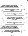
- the exemplary method (200) generally includes at (202) operating the propulsion system to power the propulsor at least in part with the gas turbine engine such that the one-way clutch couples the output shaft of the gas turbine engine to the driveshaft of the propulsor. More specifically, for the exemplary aspect of FIG. 8 , operating the propulsion system to power the propulsor at least in part with the gas turbine engine at (202) includes at (204) operating the electric machine as an electric generator. With such an exemplary aspect, the propulsion system may provide electrical power to, e.g., one or more power storage devices or a separate power sink.
- operating the electric machine as an electric generator at (204) includes at (206) powering a second propulsor of the propulsion system.
- a second propulsor of the propulsion system Such an exemplary aspect may be utilized with, e.g., the exemplary propulsion system described above with reference to FIG. 6 .
- operating the propulsion system to power the propulsor at least in part with the gas turbine engine at (202) further includes at (208) operating the propulsion system to power the propulsor with both the gas turbine engine and the electric machine.
- operating the propulsion system at (208) includes operating the electric machine as an electric motor.
- operating the propulsion system to power the propulsor with both the gas turbine engine and the electric machine at (208) includes at (210) operating the gas turbine engine in a high power mode.
- the high power mode may be a takeoff operating mode, wherein a maximum amount of power may be desired.
- the exemplary method (200) further includes at (212) operating the propulsion system to power the propulsor at least in part with the electric machine, such that the one-way clutch decouples the output shaft of the gas turbine engine from the driveshaft of the propulsor.
- operating the propulsion system to power the propulsor at least in part with the electric machine at (212) includes at (214) operating the propulsion system to power the propulsor substantially completely with the electric machine.
- operating the propulsion system at (212) includes operating the electric machine as an electric motor.
- the one-way clutch transitions from coupling the output shaft to the driveshaft to decoupling the output shaft from the driveshaft automatically based on a torque applied to the output shaft by the gas turbine engine relative to a torque applied to the driveshaft by the electric machine.
- the one-way clutch may be configured as a passively controlled one-way clutch.
Applications Claiming Priority (1)
| Application Number | Priority Date | Filing Date | Title |
|---|---|---|---|
| US15/377,080 US10837304B2 (en) | 2016-12-13 | 2016-12-13 | Hybrid-electric drive system |
Publications (2)
| Publication Number | Publication Date |
|---|---|
| EP3335995A1 true EP3335995A1 (de) | 2018-06-20 |
| EP3335995B1 EP3335995B1 (de) | 2023-05-31 |
Family
ID=60673307
Family Applications (1)
| Application Number | Title | Priority Date | Filing Date |
|---|---|---|---|
| EP17206819.9A Active EP3335995B1 (de) | 2016-12-13 | 2017-12-12 | Hybrid-elektrisches antriebssystem |
Country Status (6)
| Country | Link |
|---|---|
| US (1) | US10837304B2 (de) |
| EP (1) | EP3335995B1 (de) |
| JP (1) | JP7026989B2 (de) |
| CN (1) | CN108216546B (de) |
| BR (1) | BR102017025528A2 (de) |
| CA (1) | CA2987227C (de) |
Cited By (11)
| Publication number | Priority date | Publication date | Assignee | Title |
|---|---|---|---|---|
| EP3530928A1 (de) * | 2018-02-26 | 2019-08-28 | The Boeing Company | Hybridturbinenstrahltriebwerk und verfahren zum betrieb davon |
| EP3556659A1 (de) * | 2018-04-19 | 2019-10-23 | The Boeing Company | Hybridantriebsmotoren für flugzeuge |
| EP3597883A1 (de) * | 2018-07-19 | 2020-01-22 | United Technologies Corporation | Gleichstrommotoren und -generatoren für fangetriebesystem für flugzeughybridantrieb |
| EP3722577A1 (de) * | 2019-04-10 | 2020-10-14 | Raytheon Technologies Corporation | Variables gasturbinentriebwerk mit mehrfachantrieb |
| US10968825B2 (en) | 2018-04-19 | 2021-04-06 | The Boeing Company | Flow multiplier systems for aircraft |
| EP3805107A1 (de) * | 2019-10-08 | 2021-04-14 | Airbus SAS | Hybridantriebssystem für flugzeuge, verfahren zum betrieb eines hybridantriebssystems und hybridflugzeug |
| US10981660B2 (en) | 2018-04-19 | 2021-04-20 | The Boeing Company | Hybrid propulsion engines for aircraft |
| US20210300574A1 (en) * | 2019-12-03 | 2021-09-30 | Pratt & Whitney Canada Corp. | Aircraft propulsion system and methods of feathering |
| EP3910174A1 (de) * | 2020-05-15 | 2021-11-17 | Pratt & Whitney Canada Corp. | Gegenstromgasturbinentriebwerk mit elektromotor |
| EP3957843A1 (de) * | 2020-05-15 | 2022-02-23 | Pratt & Whitney Canada Corp. | Hybrid-gasturbinentriebwerk mit elektromotor und stromgenerator |
| WO2022162315A1 (fr) | 2021-02-01 | 2022-08-04 | Safran Transmission Systems | Turbomachine pour un aéronef comprenant des machines électriques |
Families Citing this family (36)
| Publication number | Priority date | Publication date | Assignee | Title |
|---|---|---|---|---|
| ES2932348T3 (es) * | 2018-06-20 | 2023-01-18 | Airbus Operations Slu | Turbomáquina para una aeronave |
| CN110816800B (zh) * | 2018-08-07 | 2022-02-11 | 大连理工大学 | 柴燃联合动力装置和氢燃料电池混合动力系统及其燃料供给方法 |
| US11015480B2 (en) * | 2018-08-21 | 2021-05-25 | General Electric Company | Feed forward load sensing for hybrid electric systems |
| FR3087421B1 (fr) * | 2018-10-17 | 2022-03-04 | Voltaero | Engin comprenant un groupe motopropulseur hybride et procede de pilotage correspondant |
| FR3087820B1 (fr) * | 2018-10-26 | 2020-10-16 | Safran Aircraft Engines | Turbomachine d'aeronef equipee d'une machine electrique |
| US11370554B2 (en) | 2018-11-08 | 2022-06-28 | Rolls-Royce North American Technologies, Inc. | Hybrid propulsion systems |
| US11159024B2 (en) | 2018-11-08 | 2021-10-26 | Rolls-Royce North American Technologies, Inc. | Electrical architecture for hybrid propulsion |
| US10759540B2 (en) | 2018-11-08 | 2020-09-01 | Rolls-Royce North American Technologies, Inc. | Hybrid propulsion systems |
| US11225881B2 (en) | 2018-11-08 | 2022-01-18 | Rolls-Royce North American Technologies, Inc. | Hybrid propulsion systems |
| US20220055743A1 (en) * | 2018-12-27 | 2022-02-24 | Honda Motor Co., Ltd. | Flying object |
| WO2020137105A1 (ja) * | 2018-12-27 | 2020-07-02 | 本田技研工業株式会社 | 飛行体 |
| US11939074B2 (en) | 2018-12-27 | 2024-03-26 | Honda Motor Co., Ltd. | Flying body with a control section having a plurality of operational modes |
| CN109649618A (zh) * | 2019-01-11 | 2019-04-19 | 中国科学院沈阳自动化研究所 | 一体化水空两用推进器 |
| US11732639B2 (en) | 2019-03-01 | 2023-08-22 | Pratt & Whitney Canada Corp. | Mechanical disconnects for parallel power lanes in hybrid electric propulsion systems |
| US11628942B2 (en) * | 2019-03-01 | 2023-04-18 | Pratt & Whitney Canada Corp. | Torque ripple control for an aircraft power train |
| WO2020180370A1 (en) * | 2019-03-01 | 2020-09-10 | United Technologies Advanced Projects Inc. | Aircraft propulsion system having hybrid-electric powerplant and combustion powerplant |
| WO2020180377A1 (en) * | 2019-03-01 | 2020-09-10 | United Technologies Advanced Projects, Inc. | Cooling system configurations for an aircraft having hybrid-electric propulsion system |
| KR101970601B1 (ko) * | 2019-03-13 | 2019-04-19 | 문창모 | 하이브리드 전기 추진시스템을 이용하는 수직이착륙 항공기 |
| EP3941830A4 (de) * | 2019-03-18 | 2023-01-11 | Pratt & Whitney Canada Corp. | Architekturen für hybrid-elektro-antrieb |
| US10907494B2 (en) | 2019-04-30 | 2021-02-02 | Rolls-Royce North American Technologies Inc. | Parallel hybrid propulsion system |
| US11781476B2 (en) | 2019-06-25 | 2023-10-10 | Pratt & Whitney Canada Corp. | System and method for operating a multi-engine rotorcraft |
| CN110481750A (zh) * | 2019-08-19 | 2019-11-22 | 中国舰船研究设计中心 | 整体隔振的船舶单轴双机推进系统 |
| US11203439B2 (en) | 2019-10-18 | 2021-12-21 | The Boeing Company | Rotary electric engines, aircraft including the same, and associated methods |
| US10941707B1 (en) | 2019-10-18 | 2021-03-09 | The Boeing Company | Hybrid turbine engines, aircraft including the same, and associated methods |
| CN110725748B (zh) * | 2019-11-25 | 2024-04-16 | 西安空天能源动力智能制造研究院有限公司 | 一种微型涡轮电混合分布式动力装置 |
| US11519289B2 (en) * | 2019-12-06 | 2022-12-06 | Raytheon Technologies Corporation | Systems and methods for hybrid electric turbine engines |
| US11073107B1 (en) | 2020-01-24 | 2021-07-27 | Raytheon Technologies Corporation | Systems and methods for hybrid electric turbine engines |
| US20210301722A1 (en) * | 2020-03-30 | 2021-09-30 | General Electric Company | Compact turbomachine combustor |
| US11549427B2 (en) * | 2020-04-17 | 2023-01-10 | Caterpillar Inc. | Engine and fan system having an electric motor |
| US11149803B1 (en) * | 2020-06-07 | 2021-10-19 | Textron Innovations Inc. | Mechanism and method to engage/disengage a sprag clutch using actuators |
| CN112046762B (zh) * | 2020-09-07 | 2021-10-22 | 南京航空航天大学 | 基于涡桨发动机的混合动力无人机及其起降控制方法 |
| FR3117450B1 (fr) * | 2020-12-11 | 2024-03-01 | Safran Helicopter Engines | Système propulsif hybride pour un hélicoptère |
| JP2024507365A (ja) * | 2021-02-21 | 2024-02-19 | ヴェルデゴ エアロ,インコーポレイテッド | 航空宇宙ハイブリッドシステム及びその最適化した構成要素の柔軟なアーキテクチャ |
| CN112977848B (zh) * | 2021-03-30 | 2021-10-12 | 上海尚实能源科技有限公司 | 一种混合动力型涡桨发动机的动力系统 |
| US20230095723A1 (en) * | 2021-09-24 | 2023-03-30 | General Electric Company | Turbine engine with variable pitch fan |
| US20240059422A1 (en) * | 2022-08-22 | 2024-02-22 | Pratt & Whitney Canada Corp. | Multi-drive unit propulsion system for an aircraft |
Citations (7)
| Publication number | Priority date | Publication date | Assignee | Title |
|---|---|---|---|---|
| US20080006739A1 (en) * | 2005-12-02 | 2008-01-10 | Kazuhiko Mochida | Vehicle power train including at least two power sources |
| US20120209456A1 (en) * | 2011-02-15 | 2012-08-16 | Government Of The United States, As Represented By The Secretary Of The Air Force | Parallel Hybrid-Electric Propulsion Systems for Unmanned Aircraft |
| EP2735512A1 (de) * | 2012-11-26 | 2014-05-28 | Airbus Helicopters | Verfahren und Hubschrauber mit drei Triebwerken |
| DE102013209538A1 (de) * | 2013-05-23 | 2014-11-27 | Robert Bosch Gmbh | Hybridantrieb für kraftgetriebenes Luftfahrzeug, kraftgetriebenes Luftfahrzeug mit Hybridantrieb und zugehöriges Betriebsverfahren |
| EP2962885A1 (de) * | 2013-02-28 | 2016-01-06 | Axter Aerospace SL | Hybridantriebssystem für kolbenmotorflugzeuge |
| EP3002435A1 (de) * | 2014-10-03 | 2016-04-06 | Pratt & Whitney Canada Corp. | Hilfsantriebsvorrichtung für einen gasturbinenmotor |
| US20160340051A1 (en) * | 2015-05-19 | 2016-11-24 | Rolls-Royce Plc | Aircraft electrical network |
Family Cites Families (31)
| Publication number | Priority date | Publication date | Assignee | Title |
|---|---|---|---|---|
| US3673802A (en) | 1970-06-18 | 1972-07-04 | Gen Electric | Fan engine with counter rotating geared core booster |
| GB1309721A (en) | 1971-01-08 | 1973-03-14 | Secr Defence | Fan |
| US4615008A (en) | 1982-12-22 | 1986-09-30 | United Technologies Corporation | Pulse record data capture for electrostatic engine diagnostics |
| US4625280A (en) | 1982-12-28 | 1986-11-25 | United Technologies Corporation | Sectional distress isolating electrostatic engine diagnostics |
| JPS60155016A (ja) * | 1984-01-21 | 1985-08-14 | N S K Warner Kk | ワンウエイクラツチ軸受 |
| GB2195712B (en) | 1986-10-08 | 1990-08-29 | Rolls Royce Plc | A turbofan gas turbine engine |
| JP2003063260A (ja) | 2001-08-23 | 2003-03-05 | Sumitomo Heavy Ind Ltd | ハイブリッド駆動構造及び該ハイブリッド駆動構造を備えた自動車 |
| JP3811813B2 (ja) | 2001-11-21 | 2006-08-23 | 株式会社ジェイテクト | 一方向クラッチ付きプーリユニット |
| US20080184906A1 (en) * | 2007-02-07 | 2008-08-07 | Kejha Joseph B | Long range hybrid electric airplane |
| US7819625B2 (en) | 2007-05-07 | 2010-10-26 | Siemens Energy, Inc. | Abradable CMC stacked laminate ring segment for a gas turbine |
| US8177474B2 (en) | 2007-06-26 | 2012-05-15 | General Electric Company | System and method for turbine engine clearance control with rub detection |
| US7916311B2 (en) | 2008-10-31 | 2011-03-29 | General Electric Company | Method and system for inspecting blade tip clearance |
| US8393926B2 (en) | 2009-02-12 | 2013-03-12 | Twin Disc, Inc. | Hybrid marine power train system |
| JP2011161964A (ja) | 2010-02-05 | 2011-08-25 | Toyota Motor Corp | 車両の駆動装置 |
| US20120083173A1 (en) * | 2010-10-03 | 2012-04-05 | Mcmillan Scott | Marine Propulsion Devices, Systems and Methods |
| US9322280B2 (en) | 2011-08-12 | 2016-04-26 | United Technologies Corporation | Method of measuring turbine blade tip erosion |
| US20130133480A1 (en) * | 2011-11-28 | 2013-05-30 | Icr Turbine Engine Corporation | Hybrid drive train for a gas turbine engine |
| US9063030B2 (en) | 2012-02-14 | 2015-06-23 | Computational Systems, Inc. | Apparatus and method for visualizing the position of a rotating structure with respect to a stationary structure |
| JP2013169852A (ja) | 2012-02-20 | 2013-09-02 | Toyota Motor Corp | 車両の制御装置 |
| US9174741B2 (en) | 2012-07-09 | 2015-11-03 | Mcmaster University | Hybrid powertrain system |
| US9395270B2 (en) | 2012-10-19 | 2016-07-19 | Florida Power & Light Company | Method and system for monitoring rotor blades in combustion turbine engine |
| JP5571151B2 (ja) * | 2012-11-09 | 2014-08-13 | 三菱重工業株式会社 | 船舶推進装置、船舶、及び船舶推進方法 |
| CN203372386U (zh) * | 2013-06-07 | 2014-01-01 | 哈尔滨耦合动力工程技术中心有限公司 | 柴油机发电机电动机集成的船舶混合动力系统 |
| US9878796B2 (en) * | 2014-03-27 | 2018-01-30 | United Technologies Corporation | Hybrid drive for gas turbine engine |
| DE112015003310T5 (de) * | 2014-07-17 | 2017-03-30 | Japan Aerospace Exploration Agency | Motorisiertes Flugzeug und Verfahren zum Bestimmen der Leistung und Anzahl von Elektromotoren in dem motorisierten Flugzeug |
| US10430038B2 (en) | 2014-07-18 | 2019-10-01 | General Electric Company | Automated data overlay in industrial monitoring systems |
| GB201508139D0 (en) * | 2015-05-13 | 2015-06-24 | Rolls Royce Plc | Aircraft propulsion system |
| CN204726648U (zh) | 2015-06-08 | 2015-10-28 | 于海 | 一种船用混合动力装置 |
| US9789768B1 (en) * | 2015-07-06 | 2017-10-17 | Wendel Clifford Meier | Full-segregated thrust hybrid propulsion for airplanes |
| CN105416549A (zh) * | 2015-12-01 | 2016-03-23 | 北京赛思亿电气科技有限公司 | 一种基于永磁电机的柴电混合动力系统 |
| US10717539B2 (en) * | 2016-05-05 | 2020-07-21 | Pratt & Whitney Canada Corp. | Hybrid gas-electric turbine engine |
-
2016
- 2016-12-13 US US15/377,080 patent/US10837304B2/en active Active
-
2017
- 2017-11-28 BR BR102017025528-0A patent/BR102017025528A2/pt not_active Application Discontinuation
- 2017-11-30 JP JP2017229759A patent/JP7026989B2/ja active Active
- 2017-11-30 CA CA2987227A patent/CA2987227C/en active Active
- 2017-12-12 EP EP17206819.9A patent/EP3335995B1/de active Active
- 2017-12-13 CN CN201711327418.3A patent/CN108216546B/zh active Active
Patent Citations (7)
| Publication number | Priority date | Publication date | Assignee | Title |
|---|---|---|---|---|
| US20080006739A1 (en) * | 2005-12-02 | 2008-01-10 | Kazuhiko Mochida | Vehicle power train including at least two power sources |
| US20120209456A1 (en) * | 2011-02-15 | 2012-08-16 | Government Of The United States, As Represented By The Secretary Of The Air Force | Parallel Hybrid-Electric Propulsion Systems for Unmanned Aircraft |
| EP2735512A1 (de) * | 2012-11-26 | 2014-05-28 | Airbus Helicopters | Verfahren und Hubschrauber mit drei Triebwerken |
| EP2962885A1 (de) * | 2013-02-28 | 2016-01-06 | Axter Aerospace SL | Hybridantriebssystem für kolbenmotorflugzeuge |
| DE102013209538A1 (de) * | 2013-05-23 | 2014-11-27 | Robert Bosch Gmbh | Hybridantrieb für kraftgetriebenes Luftfahrzeug, kraftgetriebenes Luftfahrzeug mit Hybridantrieb und zugehöriges Betriebsverfahren |
| EP3002435A1 (de) * | 2014-10-03 | 2016-04-06 | Pratt & Whitney Canada Corp. | Hilfsantriebsvorrichtung für einen gasturbinenmotor |
| US20160340051A1 (en) * | 2015-05-19 | 2016-11-24 | Rolls-Royce Plc | Aircraft electrical network |
Cited By (19)
| Publication number | Priority date | Publication date | Assignee | Title |
|---|---|---|---|---|
| EP3530928A1 (de) * | 2018-02-26 | 2019-08-28 | The Boeing Company | Hybridturbinenstrahltriebwerk und verfahren zum betrieb davon |
| US10981660B2 (en) | 2018-04-19 | 2021-04-20 | The Boeing Company | Hybrid propulsion engines for aircraft |
| EP3556659A1 (de) * | 2018-04-19 | 2019-10-23 | The Boeing Company | Hybridantriebsmotoren für flugzeuge |
| US10968825B2 (en) | 2018-04-19 | 2021-04-06 | The Boeing Company | Flow multiplier systems for aircraft |
| US11053019B2 (en) | 2018-04-19 | 2021-07-06 | The Boeing Company | Hybrid propulsion engines for aircraft |
| EP3597883A1 (de) * | 2018-07-19 | 2020-01-22 | United Technologies Corporation | Gleichstrommotoren und -generatoren für fangetriebesystem für flugzeughybridantrieb |
| US11098655B2 (en) | 2019-04-10 | 2021-08-24 | United Technologies Corporation | Variable multiple-drive gas turbine engine |
| EP3722577A1 (de) * | 2019-04-10 | 2020-10-14 | Raytheon Technologies Corporation | Variables gasturbinentriebwerk mit mehrfachantrieb |
| EP3805107A1 (de) * | 2019-10-08 | 2021-04-14 | Airbus SAS | Hybridantriebssystem für flugzeuge, verfahren zum betrieb eines hybridantriebssystems und hybridflugzeug |
| US20210300574A1 (en) * | 2019-12-03 | 2021-09-30 | Pratt & Whitney Canada Corp. | Aircraft propulsion system and methods of feathering |
| EP4035995A1 (de) * | 2019-12-03 | 2022-08-03 | United Technologies Advanced Projects, Inc. | Flugzeugantriebssystem und verfahren zur segelstellstellung |
| EP4035996A1 (de) * | 2019-12-03 | 2022-08-03 | United Technologies Advanced Projects, Inc. | Flugzeugantriebssystem und verfahren zur segelstellstellung |
| EP3910174A1 (de) * | 2020-05-15 | 2021-11-17 | Pratt & Whitney Canada Corp. | Gegenstromgasturbinentriebwerk mit elektromotor |
| EP3957843A1 (de) * | 2020-05-15 | 2022-02-23 | Pratt & Whitney Canada Corp. | Hybrid-gasturbinentriebwerk mit elektromotor und stromgenerator |
| US11384693B2 (en) | 2020-05-15 | 2022-07-12 | Pratt & Whitney Canada Corp. | Through-flow gas turbine engine with electric motor and electric generator |
| US11624319B2 (en) | 2020-05-15 | 2023-04-11 | Pratt & Whitney Canada Corp. | Reverse-flow gas turbine engine with electric motor |
| US11686253B2 (en) | 2020-05-15 | 2023-06-27 | Pratt & Whitney Canada Corp. | Through-flow gas turbine engine with electric motor and electric generator |
| WO2022162315A1 (fr) | 2021-02-01 | 2022-08-04 | Safran Transmission Systems | Turbomachine pour un aéronef comprenant des machines électriques |
| FR3119373A1 (fr) * | 2021-02-01 | 2022-08-05 | Safran Transmission Systems | Turbomachine pour un aeronef comprenant des machines electriques |
Also Published As
| Publication number | Publication date |
|---|---|
| CA2987227A1 (en) | 2018-06-13 |
| CA2987227C (en) | 2024-02-13 |
| JP7026989B2 (ja) | 2022-03-01 |
| CN108216546B (zh) | 2021-08-24 |
| US10837304B2 (en) | 2020-11-17 |
| US20180163558A1 (en) | 2018-06-14 |
| BR102017025528A2 (pt) | 2018-08-14 |
| EP3335995B1 (de) | 2023-05-31 |
| JP2018140767A (ja) | 2018-09-13 |
| CN108216546A (zh) | 2018-06-29 |
Similar Documents
| Publication | Publication Date | Title |
|---|---|---|
| EP3335995B1 (de) | Hybrid-elektrisches antriebssystem | |
| EP2128389B1 (de) | Gasturbinenmotoranordnung | |
| EP2452879B1 (de) | Antriebssystem für ein Luftfahrzeug | |
| US20180045119A1 (en) | Geared turbofan with low spool power extraction | |
| US11193425B2 (en) | Gearbox for boost spool turbine engine | |
| US11248532B2 (en) | Hybrid electric dual spool power extraction gearbox | |
| CA3177120C (en) | A gas turbine propulsion system | |
| US11002146B1 (en) | Power generation system | |
| EP3964700A1 (de) | Gasturbinenmotor mit geteiltem verdichter | |
| US11591971B2 (en) | Hybrid transmission on propeller gearbox | |
| WO2017200665A1 (en) | System and method for an integral drive engine with a forward main gearbox | |
| EP3327276A1 (de) | Gasturbinentriebwerk | |
| EP3569507B1 (de) | Flugzeugantriebssystem | |
| US20230132364A9 (en) | Electric machine assembly for a turbine engine | |
| EP3020942B1 (de) | Gasturbine mit elektrischer maschine und deren anordnung | |
| CN109958484B (zh) | 缓解涡轮发动机中的转子弯曲的结构和方法 |
Legal Events
| Date | Code | Title | Description |
|---|---|---|---|
| PUAI | Public reference made under article 153(3) epc to a published international application that has entered the european phase |
Free format text: ORIGINAL CODE: 0009012 |
|
| STAA | Information on the status of an ep patent application or granted ep patent |
Free format text: STATUS: THE APPLICATION HAS BEEN PUBLISHED |
|
| AK | Designated contracting states |
Kind code of ref document: A1 Designated state(s): AL AT BE BG CH CY CZ DE DK EE ES FI FR GB GR HR HU IE IS IT LI LT LU LV MC MK MT NL NO PL PT RO RS SE SI SK SM TR |
|
| AX | Request for extension of the european patent |
Extension state: BA ME |
|
| STAA | Information on the status of an ep patent application or granted ep patent |
Free format text: STATUS: REQUEST FOR EXAMINATION WAS MADE |
|
| 17P | Request for examination filed |
Effective date: 20181220 |
|
| RBV | Designated contracting states (corrected) |
Designated state(s): AL AT BE BG CH CY CZ DE DK EE ES FI FR GB GR HR HU IE IS IT LI LT LU LV MC MK MT NL NO PL PT RO RS SE SI SK SM TR |
|
| STAA | Information on the status of an ep patent application or granted ep patent |
Free format text: STATUS: EXAMINATION IS IN PROGRESS |
|
| 17Q | First examination report despatched |
Effective date: 20191001 |
|
| STAA | Information on the status of an ep patent application or granted ep patent |
Free format text: STATUS: EXAMINATION IS IN PROGRESS |
|
| STAA | Information on the status of an ep patent application or granted ep patent |
Free format text: STATUS: EXAMINATION IS IN PROGRESS |
|
| GRAP | Despatch of communication of intention to grant a patent |
Free format text: ORIGINAL CODE: EPIDOSNIGR1 |
|
| STAA | Information on the status of an ep patent application or granted ep patent |
Free format text: STATUS: GRANT OF PATENT IS INTENDED |
|
| INTG | Intention to grant announced |
Effective date: 20221220 |
|
| GRAS | Grant fee paid |
Free format text: ORIGINAL CODE: EPIDOSNIGR3 |
|
| GRAA | (expected) grant |
Free format text: ORIGINAL CODE: 0009210 |
|
| STAA | Information on the status of an ep patent application or granted ep patent |
Free format text: STATUS: THE PATENT HAS BEEN GRANTED |
|
| AK | Designated contracting states |
Kind code of ref document: B1 Designated state(s): AL AT BE BG CH CY CZ DE DK EE ES FI FR GB GR HR HU IE IS IT LI LT LU LV MC MK MT NL NO PL PT RO RS SE SI SK SM TR |
|
| REG | Reference to a national code |
Ref country code: GB Ref legal event code: FG4D Ref country code: CH Ref legal event code: EP |
|
| REG | Reference to a national code |
Ref country code: AT Ref legal event code: REF Ref document number: 1570805 Country of ref document: AT Kind code of ref document: T Effective date: 20230615 Ref country code: DE Ref legal event code: R096 Ref document number: 602017069182 Country of ref document: DE |
|
| REG | Reference to a national code |
Ref country code: IE Ref legal event code: FG4D |
|
| P01 | Opt-out of the competence of the unified patent court (upc) registered |
Effective date: 20230518 |
|
| REG | Reference to a national code |
Ref country code: LT Ref legal event code: MG9D |
|
| REG | Reference to a national code |
Ref country code: NL Ref legal event code: MP Effective date: 20230531 |
|
| REG | Reference to a national code |
Ref country code: AT Ref legal event code: MK05 Ref document number: 1570805 Country of ref document: AT Kind code of ref document: T Effective date: 20230531 |
|
| PG25 | Lapsed in a contracting state [announced via postgrant information from national office to epo] |
Ref country code: SE Free format text: LAPSE BECAUSE OF FAILURE TO SUBMIT A TRANSLATION OF THE DESCRIPTION OR TO PAY THE FEE WITHIN THE PRESCRIBED TIME-LIMIT Effective date: 20230531 Ref country code: NO Free format text: LAPSE BECAUSE OF FAILURE TO SUBMIT A TRANSLATION OF THE DESCRIPTION OR TO PAY THE FEE WITHIN THE PRESCRIBED TIME-LIMIT Effective date: 20230831 Ref country code: ES Free format text: LAPSE BECAUSE OF FAILURE TO SUBMIT A TRANSLATION OF THE DESCRIPTION OR TO PAY THE FEE WITHIN THE PRESCRIBED TIME-LIMIT Effective date: 20230531 Ref country code: AT Free format text: LAPSE BECAUSE OF FAILURE TO SUBMIT A TRANSLATION OF THE DESCRIPTION OR TO PAY THE FEE WITHIN THE PRESCRIBED TIME-LIMIT Effective date: 20230531 |
|
| PG25 | Lapsed in a contracting state [announced via postgrant information from national office to epo] |
Ref country code: RS Free format text: LAPSE BECAUSE OF FAILURE TO SUBMIT A TRANSLATION OF THE DESCRIPTION OR TO PAY THE FEE WITHIN THE PRESCRIBED TIME-LIMIT Effective date: 20230531 Ref country code: PL Free format text: LAPSE BECAUSE OF FAILURE TO SUBMIT A TRANSLATION OF THE DESCRIPTION OR TO PAY THE FEE WITHIN THE PRESCRIBED TIME-LIMIT Effective date: 20230531 Ref country code: NL Free format text: LAPSE BECAUSE OF FAILURE TO SUBMIT A TRANSLATION OF THE DESCRIPTION OR TO PAY THE FEE WITHIN THE PRESCRIBED TIME-LIMIT Effective date: 20230531 Ref country code: LV Free format text: LAPSE BECAUSE OF FAILURE TO SUBMIT A TRANSLATION OF THE DESCRIPTION OR TO PAY THE FEE WITHIN THE PRESCRIBED TIME-LIMIT Effective date: 20230531 Ref country code: LT Free format text: LAPSE BECAUSE OF FAILURE TO SUBMIT A TRANSLATION OF THE DESCRIPTION OR TO PAY THE FEE WITHIN THE PRESCRIBED TIME-LIMIT Effective date: 20230531 Ref country code: IS Free format text: LAPSE BECAUSE OF FAILURE TO SUBMIT A TRANSLATION OF THE DESCRIPTION OR TO PAY THE FEE WITHIN THE PRESCRIBED TIME-LIMIT Effective date: 20230930 Ref country code: HR Free format text: LAPSE BECAUSE OF FAILURE TO SUBMIT A TRANSLATION OF THE DESCRIPTION OR TO PAY THE FEE WITHIN THE PRESCRIBED TIME-LIMIT Effective date: 20230531 Ref country code: GR Free format text: LAPSE BECAUSE OF FAILURE TO SUBMIT A TRANSLATION OF THE DESCRIPTION OR TO PAY THE FEE WITHIN THE PRESCRIBED TIME-LIMIT Effective date: 20230901 |
|
| PG25 | Lapsed in a contracting state [announced via postgrant information from national office to epo] |
Ref country code: FI Free format text: LAPSE BECAUSE OF FAILURE TO SUBMIT A TRANSLATION OF THE DESCRIPTION OR TO PAY THE FEE WITHIN THE PRESCRIBED TIME-LIMIT Effective date: 20230531 |
|
| PG25 | Lapsed in a contracting state [announced via postgrant information from national office to epo] |
Ref country code: SK Free format text: LAPSE BECAUSE OF FAILURE TO SUBMIT A TRANSLATION OF THE DESCRIPTION OR TO PAY THE FEE WITHIN THE PRESCRIBED TIME-LIMIT Effective date: 20230531 |
|
| PGFP | Annual fee paid to national office [announced via postgrant information from national office to epo] |
Ref country code: GB Payment date: 20231124 Year of fee payment: 7 |
|
| PG25 | Lapsed in a contracting state [announced via postgrant information from national office to epo] |
Ref country code: SM Free format text: LAPSE BECAUSE OF FAILURE TO SUBMIT A TRANSLATION OF THE DESCRIPTION OR TO PAY THE FEE WITHIN THE PRESCRIBED TIME-LIMIT Effective date: 20230531 Ref country code: SK Free format text: LAPSE BECAUSE OF FAILURE TO SUBMIT A TRANSLATION OF THE DESCRIPTION OR TO PAY THE FEE WITHIN THE PRESCRIBED TIME-LIMIT Effective date: 20230531 Ref country code: RO Free format text: LAPSE BECAUSE OF FAILURE TO SUBMIT A TRANSLATION OF THE DESCRIPTION OR TO PAY THE FEE WITHIN THE PRESCRIBED TIME-LIMIT Effective date: 20230531 Ref country code: PT Free format text: LAPSE BECAUSE OF FAILURE TO SUBMIT A TRANSLATION OF THE DESCRIPTION OR TO PAY THE FEE WITHIN THE PRESCRIBED TIME-LIMIT Effective date: 20231002 Ref country code: EE Free format text: LAPSE BECAUSE OF FAILURE TO SUBMIT A TRANSLATION OF THE DESCRIPTION OR TO PAY THE FEE WITHIN THE PRESCRIBED TIME-LIMIT Effective date: 20230531 Ref country code: DK Free format text: LAPSE BECAUSE OF FAILURE TO SUBMIT A TRANSLATION OF THE DESCRIPTION OR TO PAY THE FEE WITHIN THE PRESCRIBED TIME-LIMIT Effective date: 20230531 Ref country code: CZ Free format text: LAPSE BECAUSE OF FAILURE TO SUBMIT A TRANSLATION OF THE DESCRIPTION OR TO PAY THE FEE WITHIN THE PRESCRIBED TIME-LIMIT Effective date: 20230531 |
|
| PGFP | Annual fee paid to national office [announced via postgrant information from national office to epo] |
Ref country code: FR Payment date: 20231122 Year of fee payment: 7 Ref country code: DE Payment date: 20231121 Year of fee payment: 7 |
|
| REG | Reference to a national code |
Ref country code: DE Ref legal event code: R097 Ref document number: 602017069182 Country of ref document: DE |
|
| PLBE | No opposition filed within time limit |
Free format text: ORIGINAL CODE: 0009261 |
|
| STAA | Information on the status of an ep patent application or granted ep patent |
Free format text: STATUS: NO OPPOSITION FILED WITHIN TIME LIMIT |