EP3805107A1 - Hybridantriebssystem für flugzeuge, verfahren zum betrieb eines hybridantriebssystems und hybridflugzeug - Google Patents
Hybridantriebssystem für flugzeuge, verfahren zum betrieb eines hybridantriebssystems und hybridflugzeug Download PDFInfo
- Publication number
- EP3805107A1 EP3805107A1 EP19315120.6A EP19315120A EP3805107A1 EP 3805107 A1 EP3805107 A1 EP 3805107A1 EP 19315120 A EP19315120 A EP 19315120A EP 3805107 A1 EP3805107 A1 EP 3805107A1
- Authority
- EP
- European Patent Office
- Prior art keywords
- propulsion
- gas turbine
- fuel cell
- electric
- electric machine
- Prior art date
- Legal status (The legal status is an assumption and is not a legal conclusion. Google has not performed a legal analysis and makes no representation as to the accuracy of the status listed.)
- Pending
Links
- 238000000034 method Methods 0.000 title claims description 16
- 239000000446 fuel Substances 0.000 claims abstract description 107
- 239000007789 gas Substances 0.000 claims abstract description 92
- 239000001257 hydrogen Substances 0.000 claims abstract description 43
- 229910052739 hydrogen Inorganic materials 0.000 claims abstract description 43
- UFHFLCQGNIYNRP-UHFFFAOYSA-N Hydrogen Chemical compound [H][H] UFHFLCQGNIYNRP-UHFFFAOYSA-N 0.000 claims abstract description 39
- 238000006479 redox reaction Methods 0.000 claims abstract description 9
- 230000009194 climbing Effects 0.000 claims description 22
- 150000002431 hydrogen Chemical class 0.000 abstract description 4
- 239000002828 fuel tank Substances 0.000 description 19
- 239000003344 environmental pollutant Substances 0.000 description 6
- 231100000719 pollutant Toxicity 0.000 description 6
- 239000007800 oxidant agent Substances 0.000 description 5
- 230000001590 oxidative effect Effects 0.000 description 5
- 230000010354 integration Effects 0.000 description 4
- QVGXLLKOCUKJST-UHFFFAOYSA-N atomic oxygen Chemical compound [O] QVGXLLKOCUKJST-UHFFFAOYSA-N 0.000 description 3
- 239000001301 oxygen Substances 0.000 description 3
- 229910052760 oxygen Inorganic materials 0.000 description 3
- 239000003570 air Substances 0.000 description 2
- 230000005540 biological transmission Effects 0.000 description 2
- 238000002485 combustion reaction Methods 0.000 description 2
- 238000010586 diagram Methods 0.000 description 2
- 230000009977 dual effect Effects 0.000 description 2
- 239000003792 electrolyte Substances 0.000 description 2
- 230000007613 environmental effect Effects 0.000 description 2
- 230000007257 malfunction Effects 0.000 description 2
- 238000012544 monitoring process Methods 0.000 description 2
- 206010003830 Automatism Diseases 0.000 description 1
- 239000004215 Carbon black (E152) Substances 0.000 description 1
- 239000012080 ambient air Substances 0.000 description 1
- 238000001816 cooling Methods 0.000 description 1
- 238000001514 detection method Methods 0.000 description 1
- 230000000694 effects Effects 0.000 description 1
- 230000005611 electricity Effects 0.000 description 1
- 230000010006 flight Effects 0.000 description 1
- 229930195733 hydrocarbon Natural products 0.000 description 1
- 150000002430 hydrocarbons Chemical class 0.000 description 1
- 230000007935 neutral effect Effects 0.000 description 1
- XLYOFNOQVPJJNP-UHFFFAOYSA-N water Substances O XLYOFNOQVPJJNP-UHFFFAOYSA-N 0.000 description 1
Images


Classifications
-
- B—PERFORMING OPERATIONS; TRANSPORTING
- B64—AIRCRAFT; AVIATION; COSMONAUTICS
- B64D—EQUIPMENT FOR FITTING IN OR TO AIRCRAFT; FLIGHT SUITS; PARACHUTES; ARRANGEMENTS OR MOUNTING OF POWER PLANTS OR PROPULSION TRANSMISSIONS IN AIRCRAFT
- B64D27/00—Arrangement or mounting of power plant in aircraft; Aircraft characterised thereby
- B64D27/02—Aircraft characterised by the type or position of power plant
-
- B64D27/026—
-
- B64D27/40—
-
- Y—GENERAL TAGGING OF NEW TECHNOLOGICAL DEVELOPMENTS; GENERAL TAGGING OF CROSS-SECTIONAL TECHNOLOGIES SPANNING OVER SEVERAL SECTIONS OF THE IPC; TECHNICAL SUBJECTS COVERED BY FORMER USPC CROSS-REFERENCE ART COLLECTIONS [XRACs] AND DIGESTS
- Y02—TECHNOLOGIES OR APPLICATIONS FOR MITIGATION OR ADAPTATION AGAINST CLIMATE CHANGE
- Y02T—CLIMATE CHANGE MITIGATION TECHNOLOGIES RELATED TO TRANSPORTATION
- Y02T50/00—Aeronautics or air transport
- Y02T50/60—Efficient propulsion technologies, e.g. for aircraft
Definitions
- the invention relates to a hybrid propulsion system for aircrafts, a method of operating a hybrid propulsion system, and a hybrid aircraft.
- EP 2 712 013 B1 discloses a fuel cell system for an aircraft and a method for operating the fuel cell system in the aircraft.
- the fuel cell system comprises fuel cell units coupled to a hydrogen tank.
- EP 0 780 631 B1 discloses a method for the combustion of hydrogen in a burner inside a combustion chamber of a gas turbine, where hydrogen and air are injected into the burner.
- a hybrid propulsion system for aircrafts comprising at least a fuel cell unit for providing power to drive an aircraft by using hydrogen in a redox reaction, at least a gas turbine for providing power to drive the aircraft by burning hydrogen, a hydrogen source for providing the hydrogen to the fuel cell unit and/or to the gas turbine, and at least an electric propulsion unit for driving the aircraft, wherein the electric propulsion unit is electrically powered by the fuel cell unit and/or mechanically by the gas turbine in at least two different propulsion modes, and a control unit to control the power supply to the electric propulsion unit, wherein in a first propulsion mode for a first flight phase the electric propulsion unit is essentially or only powered by the fuel cell unit, and in a second propulsion mode for a second flight phase the electric propulsion unit is essentially or only powered by the gas turbine.
- 0% emissions can be achieved e.g. in cities and airports, i.e. no pollution, no CO2, NOx, SOx, other pollutants are emitted and noise is reduced due to gas turbine inoperative.
- 0% CO2 emissions can be achieved e.g. during cruise where only a residual small amount of NOx is emitted, but no SOx and no other pollutants. Thus, the pollution on the overall flying phase is reduced.
- the invention creates an innovative Zero-C dual H2 aircraft concept which combines both, H2 Burn and fuel cell propulsion in different flight phases and thus reduces harmful emissions.
- H2 Burn uses hydrogen as a fuel for e.g. a conventional gas turbine engine
- fuel cell propulsion uses the hydrogen for a redox reaction on an anode-cathode cell.
- the first propulsion mode may be applied in particular in one or more of the flight phases taxiing, take-off, first part of climbing, second part of descent and landing. In this way, 0% emissions are achieved in these phases, and there is no pollution in cities and airports, and no CO2, NOx, SOx, other pollutants are emitted and noise is reduced there.
- the second propulsion mode may be applied in particular in one or more of the flight phases second part of climbing, cruise and first part of descent. In this way, 0% CO2 emissions and a highly reduced amount of NOx are achieved during cruise and no SOx and no other pollutants are emitted in these phases.
- the electric propulsion unit may comprise at least a first electric machine for driving a propeller and/or at least a second electric machine for driving another propeller, wherein the fuel cell unit is adapted to provide electrical energy to the first electric machine and/or to the second electric machine, and wherein the gas turbine is adapted to provide mechanical energy at least to the first electric machine and to the propeller via a common shaft.
- the hybrid propulsion system is redundant. It enables also to still operate the aircraft in a safe manner in case of failure.
- the first electric machine may be adapted to convert the mechanical energy provided by the gas turbine into electrical energy, and to provide that electrical energy e.g. to the second electric machine to drive its assigned propeller.
- the control unit may comprise a failure control automatism for automatically changing from one to the other propulsion mode in case of a failure of an element of the propulsion chain, in case of a failure of the fuel cell unit and/or in case of a failure of an electric connection for delivering electrical energy to an electric machine of the electric propulsion unit, and/or in case of a failure of an electric machine of the electric propulsion unit, and/or in case of a failure of a gas turbine.
- control unit may activate a flow of hydrogen to the fuel cell unit and/or in addition to the gas turbine, and/or a flow of electrical power from the fuel cell unit to one or more of the electric machines for driving propellers, and/or in addition a flow of mechanical power from the gas turbine to both electric machines or to only one of the electric machines.
- the first propulsion mode may be applied in particular in one or more of the flight phases taxiing, take-off, first part of climbing, second part of descent and landing.
- the fuel cell unit may be powered by the hydrogen.
- the gas turbine may be powered by the hydrogen.
- a flow of hydrogen to the fuel cell unit and/or at the same time to the gas turbine may be activated, and/or a flow of electrical power from the fuel cell unit and/or in addition a flow of mechanical power from the gas turbine to both electric machines or to only one of the electric machines may be activated.
- the fuel cell unit in the first propulsion mode may provide electrical power to a first electric machine for driving a propeller and/or to a second electric machine for driving another propeller, and in the second propulsion mode the gas turbine may provide mechanical power at least to the first electric machine for driving the propeller.
- the gas turbine may provide mechanical power to a first electric machine which may transform the mechanical power to provide electrical power to a second electric machine for driving another propeller.
- electrical energy may be produced by a first electric machine which converts mechanical energy provided by the gas turbine and which may provide the electrical energy to a second electric machine for driving another propeller.
- the method comprises a failure operation in which the current propulsion mode is replaced by the other propulsion mode in case of a failure of an element of the propulsion chain, in case of a failure of the fuel cell unit, and/or in case of a failure of an electric connection delivering electrical energy to an electric machine for driving a propeller, and/or in case of a failure of an electric machine of the electric propulsion unit, and/or in case of a failure of a gas turbine.
- a hybrid propulsion system according to the invention can be used in the method according to the invention.
- the invention provides a hybrid aircraft which comprises a hybrid propulsion system according to the invention.
- FIG. 1 shows a hybrid propulsion system 10 according to a first embodiment of the invention.
- the propulsion system 10 comprises a gas turbine 11 which is connected to a fuel tank 12 which contains hydrogen, whereby the hydrogen can be supplied via duct 26 to the gas turbine 11.
- the gas turbine 11 is e.g. a conventional gas turbine for burning the hydrogen.
- a fuel cell unit 13 is connected to the fuel tank 12 via duct 25 in order to be supplied with hydrogen.
- An electric propulsion unit 14 is mechanically connected to the gas turbine 11 and electrically connected to the fuel cell unit 13 whereby both can provide energy (mechanical and electrical) to the electric propulsion unit 14, wherein the electric propulsion unit 14 is essentially powered by the fuel cell unit 13 in a first propulsion mode, whereas in a second propulsion mode the electric propulsion unit 14 is essentially powered by the gas turbine 11.
- a power control unit 27 controls the hydrogen flow from fuel tank 12 to gas turbine 11 and/or to fuel cell unit 13as well as the flow of electrical power E and mechanical power Pm to the electric propulsion unit 14.
- the electric propulsion unit 14 comprises at least an electric machine 15a which is connected to a propeller 16a and to the gas turbine 11 on a common shaft.
- the electric machine 15a receives in the first propulsion mode mechanical power Pm from the gas turbine 11 via a shaft 33a in order to drive the propeller 16a via a shaft 33b.
- the electric machine 15a receives electrical power E from the fuel cell unit 13 via an electrical connection or electric line 30 and provides it as mechanical power Pm to propeller 16a.
- the hybrid propulsion system 10 realises a Zero-C dual H2 system concept.
- the electric machine 15a receives mechanical power Pm from the gas turbine 11 and in addition electrical power E from the fuel cell unit 13.
- the electric machine 15a is fully integrated and comprises an inverter and controller with inherent safety features to control switching between the different operational modes.
- Figure 2 shows the gas turbine 11 as an enlarged view, which is known in the state of the art. It receives hydrogen from the fuel tank 12, which is indicated in the figure by arrow H 2 . On its air inlet at its front side the gas turbine 11 receives oxygen from the ambient air, which is indicated in the figure by arrow 0 2 . During operation, the gas turbine 11 burns the hydrogen, whereby energy is set free and water and NO x is produced. The energy is transformed in mechanical power and provided to the propeller 16.
- the gas turbine 11 produces 0% CO2 and works with high efficiency while it produces high power.
- the fuel cell or fuel cell unit 13 which is part of the Hybrid propulsion system 10, is shown in an enlarged view. It is known in the state of the art and comprises an anode 13a, a cathode 13b and an electrolyte 13c which is disposed between the anode 13a and the cathode 13b (see fig. 3a ).
- the fuel cell 13 receives hydrogen at a fuel input opening 17a on its anode side, as indicated by arrow H2, and it receives oxygen at an oxidant input opening 17b on its cathode side, as indicated by arrow 02 (see fig. 3b ).
- the fuel cell 13 produces 0% CO2 and works with relatively low efficiency and high power.
- a relatively big heat exchanger is foreseen.
- Depleted fuel is output at a depleted fuel output opening 18a at the anode side of the fuel cell 13.
- Depleted oxidant and H 2 O is output at a depleted oxidant and H 2 O output opening 18b at the cathode side of fuel cell 13.
- redox reaction electricity e - is output from the fuel cell 13 as indicated by arrow E, and provided to the electric machine 15a which forms an electric motor and drives the propeller 16 (see figure 1 ).
- Figure 4 shows the configuration and the operation of the hybrid propulsion system 10 depending on different flight phases of an aircraft 100.
- the hybrid propulsion system 10 is mainly or exclusively operated in a first mode M1, in which the power for taxiing, take-off and first part of climbing is solely or at least mainly generated by the fuel cell unit 13.
- a relatively low power is needed, whereas during take-off the power reaches a maximum.
- the phases taxiing and take-off have a duration of approximately 15 minutes.
- the hybrid propulsion system 10 is mainly or exclusively operated in a second mode M2, in which the power for second part of climbing, cruise and first part of descent is solely or at least mainly generated by H2 burning in the gas turbine 11.
- the needed power is essentially lower than during take-off.
- the needed power is reduced, and during descent the power is further reduced.
- the phases second part of climbing, cruise and first part of descent have a duration of approximately 35 minutes.
- the hybrid propulsion system 10 is again operated in the first mode M1 were the power is solely or at least mainly generated by the fuel cell unit 13.
- the power level is lower than during cruise.
- the second part of descent and landing phase as aduration of approximately 10 minutes.
- Figure 5 shows a hybrid propulsion system 20 according to a second embodiment of the invention.
- the propulsion system 20 comprises gas turbine 11, fuel tank 12, fuel cell unit 13 and an electric propulsion unit 24.
- Gas turbine 11, fuel tank 12 and fuel cell unit 13 are described above in detail with reference to figures 1 to 3 .
- the electric propulsion unit 24 comprises in addition to the first electric machine 15a connected to first propeller 16a and to the gas turbine 11, a second electric machine 15b connected to a second propeller 16b.
- the first electric machine is also capable to convert the mechanical energy provided by the gas turbine 11 into electrical energy, and to provide that electrical energy to the second electric machine 15b to drive the second propeller 16b.
- the second electric machine 15b and the second propeller 16b have the same characteristics as the first electric machine 15a and the first propeller 16a, which are described above in detail with reference to figures 1 to 3 .
- the fuel tank 12 containing hydrogen is connected with the fuel cell unit 13 and the gas turbine 11 by ducts 25, 26.
- the fuel cell unit 13 is connected electrically to the electric machines 15a, 15b of the electric propulsion unit 24 by electric lines 30, 31.
- Power control unit 27 controls valves 28, 29 arranged in the ducts 25, 26 respectively to control the H2 flow to the fuel cell unit 13 and to the gas turbine 11 depending on the operational phase or flight phase of the aircraft 100 as well as the electric and mechanical power transmission through the electric lines 30, 31 and shafts 33a, 33b depending on the operational phase or flight phase of the aircraft 100.
- the power control unit 27 thus provides an H2, electric and mechanical energy management within the hybrid propulsion system.
- a method of operating the hybrid propulsion system is shown in the following with reference to figures 1 , 5 and 6 , where different flow paths are described.
- Energy flow path 1 is applied during taxiing, take-off, first part of climbing, second part of descent and landing phase of aircraft 100.
- H2 flows from fuel tank 12 through ducts 25 to fuel cell 13.
- Electric energy flows from the fuel cell 13 through electric lines 30, 31 to the first and second electric machine 15a, 15b.
- Mechanical power Pm is transmitted from electric machines 15a, 15b through shafts 33b, 33c to propellers 16a, 16b. This describes the first propulsion mode M1 which is applied by the power control unit 27 during the period of these flight phases.
- the H2 powers the fuel cell 13 only and by consequence both electric machines 15a, 15b.
- the gas turbine 11 is not powered by H2.
- the valve 28 which connects the H2 tank 12 with the fuel cell unit 13 is in an open state, whereas the valve 29 which connects the H2 tank 12 with the gas turbine 11 is in closed state.
- energy flow path 2 is activated by the power control unit and will automatically apply the second propulsion mode M2.
- the H2 will power the gas turbine 11 only and by consequence the associated propeller 16a via shaft 33a, 33b through the shaft of the first electric machine 15a.
- the gas turbine 11 provides energy to the second electric machine 15b via the first electric machine 15a, which serves as a generator, and via electric lines 31, 30 electrically connecting first and second electric machines 15a, 15b.
- the second electric machine 15b serves as a motor for driving second propeller 16b.
- the fuel cell unit 13 will not be powered by H2, i.e. it will not supply power to the electric propulsion unit 24 in mode M2.
- valve 29 is controlled by the power control unit 27 to be in an open state and thus allows an H2 flow from the H2 tank 12 to the gas turbine 11 through duct 26, whereas valve 28 is controlled to be in a closed state whereby no H2 is delivered to the fuel cell unit 13.
- the propulsion mode M2 is still applied in the first part of the descent phase in this example of operating the hybrid propulsion system 20.
- the system will commute back to propulsion mode M1 in which only the fuel cell unit 13 is powered and flow path 1 is activated.
- Figure 7 shows the different propulsion modes M1 and M2 depending on the flight phases
- figures 8a to 8c show the configuration of the hybrid propulsion system 20 in the different phases according to the second embodiment.
- Figure 7 is similar to figure 4 which is described above, but further shows the propulsion power in MW (megawatts).
- Figure 8a shows the configuration of the propulsion system 20 during propulsion mode M1 applied during taxiing, take-off and first part of climbing according to the second embodiment.
- the valve 28 is in an open state and valve 29 is closed whereby H2 flows through duct 25 to the fuel cell unit 13 only.
- 2.5 MW are provided on each side of the aircraft 100 in the e.g. take-off phase.
- the fuel cell unit 13 powered by the H2 supply delivers electrical power E to both electric machines or motors, which then provide mechanical power Pm in equal shares of 1.25 MW to the propellers 16a, 16b.
- the total power on both sides of the aircraft 100 is 5 MW in this example.
- Figure 8b shows the configuration of the propulsion system 20 during propulsion mode M2 applied during second part of climbing, cruise and first part of descent.
- valve 29 is in an open state whereas valve 28 is closed whereby H2 flows to the gas turbine 11 only.
- 1.5 MW are provided on each side of the aircraft 100 in e.g. the climbing phase.
- the gas turbine 11 powered by the H2 supply delivers mechanical power PM to first electric machine 15a which acts as a generator to generate a flow of electric power E to second electric machine 15b, while it also supplies mechanical power Pm to drive its associated propeller 16a.
- the power is delivered to both propellers 16a, 16b in equal shares of 0.75 MW.
- the total power on both sides of the aircraft 100 is 3 MW in this example.
- Figure 8c shows the configuration of the propulsion system 20 during propulsion mode M1 again, to which the system commutes at the beginning of the second part of the descent phase.
- the configuration of the propulsion system 20 including the H2 flow and electric and mechanic power flows is similar to the configuration described above with reference to Figure 8a , however it generates less power.
- Figures 9a to 9c show different failure mode operations of the hybrid propulsion system 20 during e.g. take-off, which are described in the following.
- the propulsion system 20 is redundant and enables still to operate in a safe manner the aircraft 100 in case of a failure.
- Figure 9a shows the configuration of the hybrid propulsion system 20 during a fuel cell unit 13 failure in e.g. the take-off phase, in which the fuel cell 13 is inoperative or shows a malfunction.
- the system switches automatically to the H2 burning configuration.
- the second propulsion mode M2 is applied.
- H2 is supplied from fuel tank 12 to the gas turbine 11 only.
- Valve 28 is closed and valve 29 is open.
- the gas turbine 11 provides 2.5 MW to the first electric machine 15a, which forwards half of the power as electrical power E to the second electric machine 15b, and half of the power as mechanical power Pm to its associated propeller 16a.
- both propellers 16a, 16b on one side of the aircraft 100 are operative and each of them provides 1.25 MW.
- the propulsion energy on both sides of the aircraft 100 amounts to 5 MW.
- Figure 9b shows the configuration of the hybrid propulsion system 20 during an electric connection failure in e.g. the take-off phase.
- the electric connection provided by connection lines 30, 31 is interrupted.
- the system 20 activates automatically the H2 burning configuration similar to second propulsion mode M2.
- the gas turbine 11 supplies 1.25 MW.
- the fuel cell 13 provides 1.25 MW.
- H2 is supplied from fuel tank 12 to the fuel cell unit 13 and in addition to the gas turbine 11.
- Both valves 28, 29 are open and both propellers 16a, 16b on one side of the aircraft 100 are operative and each of them provides 1.25 MW. In total, the propulsion energy on both sides of the aircraft 100 amounts to 5 MW.
- Figure 9c shows the configuration of the hybrid propulsion system 20 during an electric machine failure in e.g. the take-off phase.
- the system 20 automatically activates the H2 burning automatic configuration, similar to the second operational mode M2.
- the gas turbine 11 provides 1.25 MW.
- the fuel cell 13 provides 1.25 MW.
- H2 is supplied from fuel tank 12 to the fuel cell unit 13 and in addition to the gas turbine 11. Both valves 28, 29 are open. Gas turbine 11 supplies power to its associated first electric machine 15a, and in addition fuel cell unit 13 supplies via electric lines 30, 31 electrical power E to the first electric machine 15a.
- the first propeller 16a is powered with 2.5 MW while the external second propeller 16b is not operative.
- the system 20 automatically activates the H2 burning automatic configuration, similar to the second operational mode M2.
- the fuel cell 13 further generates power.
- H2 is supplied from fuel tank 12 to the fuel cell unit 13 which supplies 1.25 MW in this example, and in addition to the gas turbine 11 which also supplies 1.25 MW in this example.
- Both valves 28, 29 are open and both propellers 16a, 16b are operative.
- Figures 10a to 10c show different failure mode operations of the hybrid propulsion system 20 during e.g. cruise, which are described in the following.
- Figure 10a shows the configuration of the hybrid propulsion system 20 during a turbine failure in the e.g. cruising phase, in which the turbine 11 is inoperative or shows a malfunction.
- the system switches automatically to the fuel cell automatic configuration.
- the first propulsion mode M1 is applied.
- H2 is supplied from fuel tank 12 to the fuel cell unit 13 only.
- Valve 29 is closed and valve 28 is open.
- the fuel cell 13 provides 1.25 MW, which is distributed by electric connections 30, 31 to both electric machines 15a, 15b whereby both propellers 16a, 16b are operative and each of them provide 0.625MW. In total, the propulsion energy on both sides of the aircraft 100 amounts to 2.5 MW.
- Figure 10b shows the configuration of the hybrid propulsion system 20 during an electric connection failure during e.g. cruise.
- the electric connection provided by connection lines 30, 31 is interrupted.
- the system 20 activates automatically the fuel cell configuration which is similar to propulsion mode M1.
- the gas turbine 11 generates power.
- H2 is supplied from fuel tank 12 to fuel cell unit 13, which provides 0.625 MW in this example, and in addition to the gas turbine 11 which also provides 0.625 MW. Both valves 28, 29 are open. Both propellers 16a, 16b on each side of the aircraft 100 are operative and each of them provides 0.625 MW.
- Figure 10c shows the configuration of the hybrid propulsion system 20 during an electric machine failure during e.g. cruise.
- the system 20 automatically activates the fuel cell automatic configuration similar to the first operational mode M1.
- the fuel cell provides power, in this example 0.625 MW.
- the gas turbine 11 provides power, in this example also 0.625 MW.
- H2 is supplied from fuel tank 12 to the fuel cell unit 13 and in addition to the gas turbine 11. Both valves 28, 29 are open. Fuel cell unit 13 supplies electrical power E to the internal first propeller 16a which also receives the mechanical power Pm from gas turbine 11. Thus, the internal first propeller 16a is operative while the external second propeller 16b is not operative.
- the system 20 automatically activates the fuel cell automatic configuration similar to the first operational mode M1.
- the gas turbine 12 provides power.
- H2 is supplied from fuel tank 12 to the gas turbine 11 which supplies 0.625 MW in this example, and in addition to the fuel cell unit 13 which also supplies 0.625 MW in this example.
- Both valves 28, 29 are open and both propellers 16a, 16b are operative.
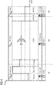
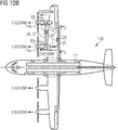
- Figure 11 shows a schematic view of an aircraft 100 equipped with the hybrid propulsion system 10 according to the first embodiment of the invention.
- a non-redundant dual-H2 concept architecture is realized.
- the system will either commute to fuel cell propulsion or to H2 burn propulsion. This is achieved by two different flow paths 1 and 2.
- Path 1 is activated during at least one of the phases taxiing, take-off, first part of climbing, second part of descent and landing, preferably in all of these phases.
- the H2 supplied by fuel tank 12 will power the fuel cell 13 only and by consequence electric machine 15a associated therewith.
- the gas turbine 11 will not be powered.
- the propulsion system is operated in a way that valve 29 provided in duct 26 is closed while valve 28 provided in duct 25 is open.
- the fuel cell 13 provides electrical power E to the electric machine 15a which acts as a motor and which is connected to propeller 16a.
- Path 2 is activated during the second part of climbing, cruise phase and first part of descent. It can also be activated during the climbing phase, preferably in both of these phases.
- the H2 supplied by fuel tank 12 will power the gas turbine 11 only and by consequence the propeller 16a.
- the fuel cell 13 will not be powered.
- the propulsion system is operated in a way that valve 29 provided in duct 26 is open and valve 28 provided in duct 25 is closed.
- the invention provides a dual-H2 concept architecture which can be redundant according to particularly preferred embodiments. It combines an H2-burn gas turbine with a fuel cell and at least an electric propulsion unit in a hybrid propulsion system.
- a fully integrated electric machine (motor/generator) including inverter/controller with inherent safety features can be part of the hybrid propulsion system.
- a pitch control management can be provided.
- a high power density technology with full redundancy can be implemented.
- the hybrid propulsion system may comprise an electric transmission system including e.g. a new cable technology, a voltage compatible with integrated and lightweight power electronics as well as high voltage protection devices.
- an electric transmission system including e.g. a new cable technology, a voltage compatible with integrated and lightweight power electronics as well as high voltage protection devices.
- one or more of the features power management (multi-source/multi-consumer), automatic reconfiguration upon failure detection as well as health monitoring can be provided.
- a fuel cell thermal management, an electric propulsion unit thermal management and/or an H2 tank thermal management can be provided in the hybrid propulsion system.
Priority Applications (1)
| Application Number | Priority Date | Filing Date | Title |
|---|---|---|---|
| EP19315120.6A EP3805107A1 (de) | 2019-10-08 | 2019-10-08 | Hybridantriebssystem für flugzeuge, verfahren zum betrieb eines hybridantriebssystems und hybridflugzeug |
Applications Claiming Priority (1)
| Application Number | Priority Date | Filing Date | Title |
|---|---|---|---|
| EP19315120.6A EP3805107A1 (de) | 2019-10-08 | 2019-10-08 | Hybridantriebssystem für flugzeuge, verfahren zum betrieb eines hybridantriebssystems und hybridflugzeug |
Publications (1)
| Publication Number | Publication Date |
|---|---|
| EP3805107A1 true EP3805107A1 (de) | 2021-04-14 |
Family
ID=68581726
Family Applications (1)
| Application Number | Title | Priority Date | Filing Date |
|---|---|---|---|
| EP19315120.6A Pending EP3805107A1 (de) | 2019-10-08 | 2019-10-08 | Hybridantriebssystem für flugzeuge, verfahren zum betrieb eines hybridantriebssystems und hybridflugzeug |
Country Status (1)
| Country | Link |
|---|---|
| EP (1) | EP3805107A1 (de) |
Cited By (17)
| Publication number | Priority date | Publication date | Assignee | Title |
|---|---|---|---|---|
| EP3885267A1 (de) * | 2020-03-27 | 2021-09-29 | Raytheon Technologies Corporation | Wasserstoffantriebssysteme für flugzeuge |
| EP4173956A1 (de) | 2021-10-29 | 2023-05-03 | Airbus S.A.S. | Hybridantriebssystem zum antreiben eines flugzeuges, verfahren zu dessen betrieb und hybridfahrzeug |
| US20230212988A1 (en) * | 2022-01-04 | 2023-07-06 | General Electric Company | Versatile control of a propulsion system with a fuel cell |
| US11719441B2 (en) | 2022-01-04 | 2023-08-08 | General Electric Company | Systems and methods for providing output products to a combustion chamber of a gas turbine engine |
| US11788474B2 (en) | 2022-03-07 | 2023-10-17 | General Electric Company | Pericritical fluid systems for turbine engines |
| US11794912B2 (en) | 2022-01-04 | 2023-10-24 | General Electric Company | Systems and methods for reducing emissions with a fuel cell |
| US11804607B2 (en) | 2022-01-21 | 2023-10-31 | General Electric Company | Cooling of a fuel cell assembly |
| US11817700B1 (en) | 2022-07-20 | 2023-11-14 | General Electric Company | Decentralized electrical power allocation system |
| US11859820B1 (en) | 2022-11-10 | 2024-01-02 | General Electric Company | Gas turbine combustion section having an integrated fuel cell assembly |
| WO2024009097A1 (en) * | 2022-07-08 | 2024-01-11 | Gkn Aerospace Services Limited | Aircraft propulsion system and method |
| US20240043133A1 (en) * | 2022-08-04 | 2024-02-08 | The Boeing Company | Hybrid-electric powertrains for aircraft |
| US11923586B1 (en) | 2022-11-10 | 2024-03-05 | General Electric Company | Gas turbine combustion section having an integrated fuel cell assembly |
| US11927142B2 (en) | 2022-07-25 | 2024-03-12 | General Electric Company | Systems and methods for controlling fuel coke formation |
| US11933216B2 (en) | 2022-01-04 | 2024-03-19 | General Electric Company | Systems and methods for providing output products to a combustion chamber of a gas turbine engine |
| US11946378B2 (en) | 2022-04-13 | 2024-04-02 | General Electric Company | Transient control of a thermal transport bus |
| US11967743B2 (en) | 2022-02-21 | 2024-04-23 | General Electric Company | Modular fuel cell assembly |
| US11970282B2 (en) | 2022-01-05 | 2024-04-30 | General Electric Company | Aircraft thrust management with a fuel cell |
Citations (6)
| Publication number | Priority date | Publication date | Assignee | Title |
|---|---|---|---|---|
| EP0780631B1 (de) | 1995-12-19 | 2003-10-29 | Airbus Deutschland GmbH | Verfahren und Brenner zum Verbrennen von Wasserstoff |
| DE102014224637A1 (de) * | 2014-12-02 | 2016-06-02 | Georgi Atanasov | Hybrid-Elektro-Antriebssystem für ein Flugzeug |
| DE102015215130A1 (de) * | 2015-08-07 | 2017-02-09 | Siemens Aktiengesellschaft | Antriebssystem und Verfahren zum Antreiben eines Vortriebsmittels eines Fahrzeugs |
| EP3241753A1 (de) * | 2016-05-06 | 2017-11-08 | Rolls-Royce Corporation | Optionales hybrides antriebssystem |
| EP3335995A1 (de) * | 2016-12-13 | 2018-06-20 | General Electric Company | Hybrid-elektrisches antriebssystem |
| EP2712013B1 (de) | 2012-09-20 | 2018-08-15 | Airbus Operations GmbH | Brennstoffzellensystem für ein Flugzeug, Verfahren zum Betrieb eines Brennstoffzellensystems in einem Flugzeug und Flugzeug mit solch einem Brennstoffzellensystem |
-
2019
- 2019-10-08 EP EP19315120.6A patent/EP3805107A1/de active Pending
Patent Citations (6)
| Publication number | Priority date | Publication date | Assignee | Title |
|---|---|---|---|---|
| EP0780631B1 (de) | 1995-12-19 | 2003-10-29 | Airbus Deutschland GmbH | Verfahren und Brenner zum Verbrennen von Wasserstoff |
| EP2712013B1 (de) | 2012-09-20 | 2018-08-15 | Airbus Operations GmbH | Brennstoffzellensystem für ein Flugzeug, Verfahren zum Betrieb eines Brennstoffzellensystems in einem Flugzeug und Flugzeug mit solch einem Brennstoffzellensystem |
| DE102014224637A1 (de) * | 2014-12-02 | 2016-06-02 | Georgi Atanasov | Hybrid-Elektro-Antriebssystem für ein Flugzeug |
| DE102015215130A1 (de) * | 2015-08-07 | 2017-02-09 | Siemens Aktiengesellschaft | Antriebssystem und Verfahren zum Antreiben eines Vortriebsmittels eines Fahrzeugs |
| EP3241753A1 (de) * | 2016-05-06 | 2017-11-08 | Rolls-Royce Corporation | Optionales hybrides antriebssystem |
| EP3335995A1 (de) * | 2016-12-13 | 2018-06-20 | General Electric Company | Hybrid-elektrisches antriebssystem |
Cited By (18)
| Publication number | Priority date | Publication date | Assignee | Title |
|---|---|---|---|---|
| EP3885267A1 (de) * | 2020-03-27 | 2021-09-29 | Raytheon Technologies Corporation | Wasserstoffantriebssysteme für flugzeuge |
| US11511872B2 (en) | 2020-03-27 | 2022-11-29 | Raytheon Technologies Corporation | Hydrogen propulsion systems for aircraft |
| EP4173956A1 (de) | 2021-10-29 | 2023-05-03 | Airbus S.A.S. | Hybridantriebssystem zum antreiben eines flugzeuges, verfahren zu dessen betrieb und hybridfahrzeug |
| US11794912B2 (en) | 2022-01-04 | 2023-10-24 | General Electric Company | Systems and methods for reducing emissions with a fuel cell |
| US11719441B2 (en) | 2022-01-04 | 2023-08-08 | General Electric Company | Systems and methods for providing output products to a combustion chamber of a gas turbine engine |
| US11933216B2 (en) | 2022-01-04 | 2024-03-19 | General Electric Company | Systems and methods for providing output products to a combustion chamber of a gas turbine engine |
| US20230212988A1 (en) * | 2022-01-04 | 2023-07-06 | General Electric Company | Versatile control of a propulsion system with a fuel cell |
| US11970282B2 (en) | 2022-01-05 | 2024-04-30 | General Electric Company | Aircraft thrust management with a fuel cell |
| US11804607B2 (en) | 2022-01-21 | 2023-10-31 | General Electric Company | Cooling of a fuel cell assembly |
| US11967743B2 (en) | 2022-02-21 | 2024-04-23 | General Electric Company | Modular fuel cell assembly |
| US11788474B2 (en) | 2022-03-07 | 2023-10-17 | General Electric Company | Pericritical fluid systems for turbine engines |
| US11946378B2 (en) | 2022-04-13 | 2024-04-02 | General Electric Company | Transient control of a thermal transport bus |
| WO2024009097A1 (en) * | 2022-07-08 | 2024-01-11 | Gkn Aerospace Services Limited | Aircraft propulsion system and method |
| US11817700B1 (en) | 2022-07-20 | 2023-11-14 | General Electric Company | Decentralized electrical power allocation system |
| US11927142B2 (en) | 2022-07-25 | 2024-03-12 | General Electric Company | Systems and methods for controlling fuel coke formation |
| US20240043133A1 (en) * | 2022-08-04 | 2024-02-08 | The Boeing Company | Hybrid-electric powertrains for aircraft |
| US11923586B1 (en) | 2022-11-10 | 2024-03-05 | General Electric Company | Gas turbine combustion section having an integrated fuel cell assembly |
| US11859820B1 (en) | 2022-11-10 | 2024-01-02 | General Electric Company | Gas turbine combustion section having an integrated fuel cell assembly |
Similar Documents
| Publication | Publication Date | Title |
|---|---|---|
| EP3805107A1 (de) | Hybridantriebssystem für flugzeuge, verfahren zum betrieb eines hybridantriebssystems und hybridflugzeug | |
| EP3650350B1 (de) | Hybridantriebssystem | |
| CN108691653B (zh) | 用于混合电力架构的电力分配系统和方法 | |
| RU2690608C2 (ru) | Архитектура силовой системы многомоторного вертолета и соответствующий вертолет | |
| US11866180B2 (en) | Hybrid propulsion systems | |
| EP2086834B1 (de) | Antriebsvorrichtung mit mehreren energieumwandlern für ein luftfahrzeug | |
| US8950703B2 (en) | Independent power generation in aircraft | |
| US10759540B2 (en) | Hybrid propulsion systems | |
| US11159024B2 (en) | Electrical architecture for hybrid propulsion | |
| US20130147204A1 (en) | Hybrid Drive And Energy System For Aircraft | |
| US20130099560A1 (en) | Multiple source electrical power distribution in aircraft | |
| WO2008064881A1 (en) | Propulsion device for operation with a plurality of fuels for an aircraft | |
| US9821918B2 (en) | Aircraft comprising a control device for a jet pipe nozzle with variable cross-section powered by two independent electrical power supplies | |
| CN108252807B (zh) | 涡轮电动式的发动机推进系统 | |
| CN115108028A (zh) | 用于旋翼飞行器的混合动力电动系统 | |
| CN116261546A (zh) | 具有用于低排放巡航的驱动和动力系统的飞机 | |
| US20180237130A1 (en) | Aircraft using energy recovery systems | |
| Oyori et al. | Power management system for the electric taxiing system incorporating the more electric architecture | |
| Oyori et al. | Conceptual study of low-pressure spool-generating architecture for more electric aircraft | |
| Volchenko et al. | Hybrid and electric propulsion system of aircrafts | |
| CN219115720U (zh) | 一种电推进系统能源架构及飞机 | |
| EP4173956A1 (de) | Hybridantriebssystem zum antreiben eines flugzeuges, verfahren zu dessen betrieb und hybridfahrzeug | |
| CN115892483A (zh) | 一种电推进系统能源架构及供能方法 | |
| US20230358191A1 (en) | Stowable electric-hybrid propfan | |
| US20230415904A1 (en) | Method for converting an airplane with thermic reaction propulsion motor to electrical reaction propulsion airplane and the electric airplane thereof |
Legal Events
| Date | Code | Title | Description |
|---|---|---|---|
| PUAI | Public reference made under article 153(3) epc to a published international application that has entered the european phase |
Free format text: ORIGINAL CODE: 0009012 |
|
| STAA | Information on the status of an ep patent application or granted ep patent |
Free format text: STATUS: THE APPLICATION HAS BEEN PUBLISHED |
|
| AK | Designated contracting states |
Kind code of ref document: A1 Designated state(s): AL AT BE BG CH CY CZ DE DK EE ES FI FR GB GR HR HU IE IS IT LI LT LU LV MC MK MT NL NO PL PT RO RS SE SI SK SM TR |
|
| AX | Request for extension of the european patent |
Extension state: BA ME |
|
| STAA | Information on the status of an ep patent application or granted ep patent |
Free format text: STATUS: REQUEST FOR EXAMINATION WAS MADE |
|
| 17P | Request for examination filed |
Effective date: 20211014 |
|
| RBV | Designated contracting states (corrected) |
Designated state(s): AL AT BE BG CH CY CZ DE DK EE ES FI FR GB GR HR HU IE IS IT LI LT LU LV MC MK MT NL NO PL PT RO RS SE SI SK SM TR |
|
| STAA | Information on the status of an ep patent application or granted ep patent |
Free format text: STATUS: EXAMINATION IS IN PROGRESS |
|
| 17Q | First examination report despatched |
Effective date: 20221122 |