EP3530928A1 - Hybridturbinenstrahltriebwerk und verfahren zum betrieb davon - Google Patents
Hybridturbinenstrahltriebwerk und verfahren zum betrieb davon Download PDFInfo
- Publication number
- EP3530928A1 EP3530928A1 EP18213871.9A EP18213871A EP3530928A1 EP 3530928 A1 EP3530928 A1 EP 3530928A1 EP 18213871 A EP18213871 A EP 18213871A EP 3530928 A1 EP3530928 A1 EP 3530928A1
- Authority
- EP
- European Patent Office
- Prior art keywords
- clutch
- thrust
- rotary shaft
- generating device
- machine
- Prior art date
- Legal status (The legal status is an assumption and is not a legal conclusion. Google has not performed a legal analysis and makes no representation as to the accuracy of the status listed.)
- Granted
Links
- 238000000034 method Methods 0.000 title claims abstract description 71
- 239000000446 fuel Substances 0.000 claims description 19
- 230000007704 transition Effects 0.000 claims description 6
- 230000001143 conditioned effect Effects 0.000 description 18
- 238000004146 energy storage Methods 0.000 description 13
- 238000002485 combustion reaction Methods 0.000 description 11
- 238000011144 upstream manufacturing Methods 0.000 description 9
- 230000003247 decreasing effect Effects 0.000 description 7
- 230000002441 reversible effect Effects 0.000 description 7
- 238000005381 potential energy Methods 0.000 description 6
- 230000001133 acceleration Effects 0.000 description 3
- 230000006641 stabilisation Effects 0.000 description 3
- 238000011105 stabilization Methods 0.000 description 3
- 230000001360 synchronised effect Effects 0.000 description 3
- 230000000694 effects Effects 0.000 description 2
- 230000014509 gene expression Effects 0.000 description 2
- 239000003381 stabilizer Substances 0.000 description 2
- 239000013589 supplement Substances 0.000 description 2
- 239000004020 conductor Substances 0.000 description 1
- 230000003111 delayed effect Effects 0.000 description 1
- 230000002093 peripheral effect Effects 0.000 description 1
- 238000010248 power generation Methods 0.000 description 1
- 238000004513 sizing Methods 0.000 description 1
Images


Classifications
-
- F—MECHANICAL ENGINEERING; LIGHTING; HEATING; WEAPONS; BLASTING
- F01—MACHINES OR ENGINES IN GENERAL; ENGINE PLANTS IN GENERAL; STEAM ENGINES
- F01D—NON-POSITIVE DISPLACEMENT MACHINES OR ENGINES, e.g. STEAM TURBINES
- F01D7/00—Rotors with blades adjustable in operation; Control thereof
-
- B—PERFORMING OPERATIONS; TRANSPORTING
- B64—AIRCRAFT; AVIATION; COSMONAUTICS
- B64D—EQUIPMENT FOR FITTING IN OR TO AIRCRAFT; FLIGHT SUITS; PARACHUTES; ARRANGEMENT OR MOUNTING OF POWER PLANTS OR PROPULSION TRANSMISSIONS IN AIRCRAFT
- B64D27/00—Arrangement or mounting of power plants in aircraft; Aircraft characterised by the type or position of power plants
- B64D27/02—Aircraft characterised by the type or position of power plants
- B64D27/10—Aircraft characterised by the type or position of power plants of gas-turbine type
-
- B—PERFORMING OPERATIONS; TRANSPORTING
- B64—AIRCRAFT; AVIATION; COSMONAUTICS
- B64D—EQUIPMENT FOR FITTING IN OR TO AIRCRAFT; FLIGHT SUITS; PARACHUTES; ARRANGEMENT OR MOUNTING OF POWER PLANTS OR PROPULSION TRANSMISSIONS IN AIRCRAFT
- B64D27/00—Arrangement or mounting of power plants in aircraft; Aircraft characterised by the type or position of power plants
- B64D27/02—Aircraft characterised by the type or position of power plants
- B64D27/24—Aircraft characterised by the type or position of power plants using steam or spring force
-
- B—PERFORMING OPERATIONS; TRANSPORTING
- B64—AIRCRAFT; AVIATION; COSMONAUTICS
- B64D—EQUIPMENT FOR FITTING IN OR TO AIRCRAFT; FLIGHT SUITS; PARACHUTES; ARRANGEMENT OR MOUNTING OF POWER PLANTS OR PROPULSION TRANSMISSIONS IN AIRCRAFT
- B64D35/00—Transmitting power from power plants to propellers or rotors; Arrangements of transmissions
- B64D35/08—Transmitting power from power plants to propellers or rotors; Arrangements of transmissions characterised by the transmission being driven by a plurality of power plants
-
- F—MECHANICAL ENGINEERING; LIGHTING; HEATING; WEAPONS; BLASTING
- F01—MACHINES OR ENGINES IN GENERAL; ENGINE PLANTS IN GENERAL; STEAM ENGINES
- F01D—NON-POSITIVE DISPLACEMENT MACHINES OR ENGINES, e.g. STEAM TURBINES
- F01D15/00—Adaptations of machines or engines for special use; Combinations of engines with devices driven thereby
- F01D15/10—Adaptations for driving, or combinations with, electric generators
-
- F—MECHANICAL ENGINEERING; LIGHTING; HEATING; WEAPONS; BLASTING
- F02—COMBUSTION ENGINES; HOT-GAS OR COMBUSTION-PRODUCT ENGINE PLANTS
- F02C—GAS-TURBINE PLANTS; AIR INTAKES FOR JET-PROPULSION PLANTS; CONTROLLING FUEL SUPPLY IN AIR-BREATHING JET-PROPULSION PLANTS
- F02C6/00—Plural gas-turbine plants; Combinations of gas-turbine plants with other apparatus; Adaptations of gas-turbine plants for special use
- F02C6/14—Gas-turbine plants having means for storing energy, e.g. for meeting peak loads
-
- F—MECHANICAL ENGINEERING; LIGHTING; HEATING; WEAPONS; BLASTING
- F02—COMBUSTION ENGINES; HOT-GAS OR COMBUSTION-PRODUCT ENGINE PLANTS
- F02C—GAS-TURBINE PLANTS; AIR INTAKES FOR JET-PROPULSION PLANTS; CONTROLLING FUEL SUPPLY IN AIR-BREATHING JET-PROPULSION PLANTS
- F02C7/00—Features, components parts, details or accessories, not provided for in, or of interest apart form groups F02C1/00 - F02C6/00; Air intakes for jet-propulsion plants
- F02C7/26—Starting; Ignition
-
- F—MECHANICAL ENGINEERING; LIGHTING; HEATING; WEAPONS; BLASTING
- F02—COMBUSTION ENGINES; HOT-GAS OR COMBUSTION-PRODUCT ENGINE PLANTS
- F02C—GAS-TURBINE PLANTS; AIR INTAKES FOR JET-PROPULSION PLANTS; CONTROLLING FUEL SUPPLY IN AIR-BREATHING JET-PROPULSION PLANTS
- F02C7/00—Features, components parts, details or accessories, not provided for in, or of interest apart form groups F02C1/00 - F02C6/00; Air intakes for jet-propulsion plants
- F02C7/36—Power transmission arrangements between the different shafts of the gas turbine plant, or between the gas-turbine plant and the power user
-
- F—MECHANICAL ENGINEERING; LIGHTING; HEATING; WEAPONS; BLASTING
- F02—COMBUSTION ENGINES; HOT-GAS OR COMBUSTION-PRODUCT ENGINE PLANTS
- F02K—JET-PROPULSION PLANTS
- F02K3/00—Plants including a gas turbine driving a compressor or a ducted fan
-
- F—MECHANICAL ENGINEERING; LIGHTING; HEATING; WEAPONS; BLASTING
- F02—COMBUSTION ENGINES; HOT-GAS OR COMBUSTION-PRODUCT ENGINE PLANTS
- F02K—JET-PROPULSION PLANTS
- F02K3/00—Plants including a gas turbine driving a compressor or a ducted fan
- F02K3/02—Plants including a gas turbine driving a compressor or a ducted fan in which part of the working fluid by-passes the turbine and combustion chamber
- F02K3/04—Plants including a gas turbine driving a compressor or a ducted fan in which part of the working fluid by-passes the turbine and combustion chamber the plant including ducted fans, i.e. fans with high volume, low pressure outputs, for augmenting the jet thrust, e.g. of double-flow type
- F02K3/06—Plants including a gas turbine driving a compressor or a ducted fan in which part of the working fluid by-passes the turbine and combustion chamber the plant including ducted fans, i.e. fans with high volume, low pressure outputs, for augmenting the jet thrust, e.g. of double-flow type with front fan
-
- F—MECHANICAL ENGINEERING; LIGHTING; HEATING; WEAPONS; BLASTING
- F02—COMBUSTION ENGINES; HOT-GAS OR COMBUSTION-PRODUCT ENGINE PLANTS
- F02K—JET-PROPULSION PLANTS
- F02K5/00—Plants including an engine, other than a gas turbine, driving a compressor or a ducted fan
-
- H—ELECTRICITY
- H02—GENERATION; CONVERSION OR DISTRIBUTION OF ELECTRIC POWER
- H02K—DYNAMO-ELECTRIC MACHINES
- H02K7/00—Arrangements for handling mechanical energy structurally associated with dynamo-electric machines, e.g. structural association with mechanical driving motors or auxiliary dynamo-electric machines
- H02K7/10—Structural association with clutches, brakes, gears, pulleys or mechanical starters
-
- H—ELECTRICITY
- H02—GENERATION; CONVERSION OR DISTRIBUTION OF ELECTRIC POWER
- H02P—CONTROL OR REGULATION OF ELECTRIC MOTORS, ELECTRIC GENERATORS OR DYNAMO-ELECTRIC CONVERTERS; CONTROLLING TRANSFORMERS, REACTORS OR CHOKE COILS
- H02P17/00—Arrangements for controlling dynamo-electric gears
-
- B—PERFORMING OPERATIONS; TRANSPORTING
- B64—AIRCRAFT; AVIATION; COSMONAUTICS
- B64D—EQUIPMENT FOR FITTING IN OR TO AIRCRAFT; FLIGHT SUITS; PARACHUTES; ARRANGEMENT OR MOUNTING OF POWER PLANTS OR PROPULSION TRANSMISSIONS IN AIRCRAFT
- B64D27/00—Arrangement or mounting of power plants in aircraft; Aircraft characterised by the type or position of power plants
- B64D27/02—Aircraft characterised by the type or position of power plants
- B64D27/026—Aircraft characterised by the type or position of power plants comprising different types of power plants, e.g. combination of a piston engine and a gas-turbine
-
- F—MECHANICAL ENGINEERING; LIGHTING; HEATING; WEAPONS; BLASTING
- F05—INDEXING SCHEMES RELATING TO ENGINES OR PUMPS IN VARIOUS SUBCLASSES OF CLASSES F01-F04
- F05D—INDEXING SCHEME FOR ASPECTS RELATING TO NON-POSITIVE-DISPLACEMENT MACHINES OR ENGINES, GAS-TURBINES OR JET-PROPULSION PLANTS
- F05D2220/00—Application
- F05D2220/30—Application in turbines
- F05D2220/32—Application in turbines in gas turbines
- F05D2220/323—Application in turbines in gas turbines for aircraft propulsion, e.g. jet engines
-
- F—MECHANICAL ENGINEERING; LIGHTING; HEATING; WEAPONS; BLASTING
- F05—INDEXING SCHEMES RELATING TO ENGINES OR PUMPS IN VARIOUS SUBCLASSES OF CLASSES F01-F04
- F05D—INDEXING SCHEME FOR ASPECTS RELATING TO NON-POSITIVE-DISPLACEMENT MACHINES OR ENGINES, GAS-TURBINES OR JET-PROPULSION PLANTS
- F05D2220/00—Application
- F05D2220/70—Application in combination with
- F05D2220/76—Application in combination with an electrical generator
-
- F—MECHANICAL ENGINEERING; LIGHTING; HEATING; WEAPONS; BLASTING
- F05—INDEXING SCHEMES RELATING TO ENGINES OR PUMPS IN VARIOUS SUBCLASSES OF CLASSES F01-F04
- F05D—INDEXING SCHEME FOR ASPECTS RELATING TO NON-POSITIVE-DISPLACEMENT MACHINES OR ENGINES, GAS-TURBINES OR JET-PROPULSION PLANTS
- F05D2260/00—Function
- F05D2260/40—Transmission of power
- F05D2260/402—Transmission of power through friction drives
- F05D2260/4023—Transmission of power through friction drives through a friction clutch
-
- F—MECHANICAL ENGINEERING; LIGHTING; HEATING; WEAPONS; BLASTING
- F05—INDEXING SCHEMES RELATING TO ENGINES OR PUMPS IN VARIOUS SUBCLASSES OF CLASSES F01-F04
- F05D—INDEXING SCHEME FOR ASPECTS RELATING TO NON-POSITIVE-DISPLACEMENT MACHINES OR ENGINES, GAS-TURBINES OR JET-PROPULSION PLANTS
- F05D2260/00—Function
- F05D2260/42—Storage of energy
-
- F—MECHANICAL ENGINEERING; LIGHTING; HEATING; WEAPONS; BLASTING
- F16—ENGINEERING ELEMENTS AND UNITS; GENERAL MEASURES FOR PRODUCING AND MAINTAINING EFFECTIVE FUNCTIONING OF MACHINES OR INSTALLATIONS; THERMAL INSULATION IN GENERAL
- F16D—COUPLINGS FOR TRANSMITTING ROTATION; CLUTCHES; BRAKES
- F16D23/00—Details of mechanically-actuated clutches not specific for one distinct type
- F16D23/02—Arrangements for synchronisation, also for power-operated clutches
Definitions
- the present disclosure relates generally to hybrid turbine jet engines and to methods of operating hybrid turbine jet engines.
- Turbine jet engines may be utilized to power and/or to convey an aircraft, such as an airplane. Such turbine jet engines rely upon gas expansion, from combustion of a fuel, to provide a motive force for rotation of one or more compressors and/or turbines. As such, turbine jet engines may require a constant supply of fuel and may combust, or consume, the fuel continuously during operation thereof.
- While turbine jet engines may be highly effective at generating thrust, there may be inefficiencies associated with operation thereof.
- the turbine jet engine must be sized for a maximum needed thrust, such as may be utilized during acceleration of an aircraft that utilizes the turbine jet engine, during take-off of the aircraft, and/or during an engine-out condition of the aircraft.
- a maximum needed thrust such as may be utilized during acceleration of an aircraft that utilizes the turbine jet engine, during take-off of the aircraft, and/or during an engine-out condition of the aircraft.
- an operational efficiency of the turbine jet engine at constant, or cruise, speeds may be less than otherwise would be possible were the turbine jet engine sized for constant speeds.
- kinetic energy of the aircraft may be lost.
- potential energy of the aircraft may be lost. This lost kinetic and/or potential energy generally is not recovered and represents a loss of energy that initially was utilized to accelerate the aircraft and/or to attain a given altitude, respectively.
- the hybrid turbine engines include a first thrust-generating device that includes a turbine with a turbine rotary shaft.
- the hybrid turbine engines also include a clutch, which includes a clutch input that is operatively coupled to the turbine rotary shaft and a clutch output.
- the clutch defines an engaged state, in which the clutch input is rotationally coupled to the clutch output, and a disengaged state, in which the clutch input is rotationally decoupled from the clutch output.
- the hybrid turbine engines also include a rotary electric machine including a machine rotary shaft that is operatively coupled to the clutch output.
- the hybrid turbine engines further include a second thrust-generating device, which is operatively coupled to the machine rotary shaft, and an electric power system.
- the rotary electric machine is configured to selectively receive an electric power output from the electric power system and to generate an output torque to rotate the second thrust-generating device, via the machine rotary shaft, responsive to receipt of the electric power input.
- the rotary electric machine also is configured to selectively receive in an input torque from the machine rotary shaft, to generate an electric power output responsive to receipt of the input torque, and to provide the electric power output to the electric power system.
- the rotary electric machine may be configured to selectively receive the electric power output from the electric power system and to generate the output torque when the clutch is in the engaged state and/or in the disengaged state. As an example, when the clutch is in the engaged state, the rotary electric machine may be utilized to start the hybrid turbine engine.
- the methods include combusting a fuel within a turbine of a first thrust-generating device to rotate a turbine rotary shaft of the first thrust-generating device.
- the methods also include selectively providing an electric power input to a rotary electric machine to generate an output torque that rotates a machine rotary shaft and a second thrust-generating device.
- the methods further include selectively receiving an input torque from the second thrust-generating device with the rotary electric machine and generating an electric power output with the rotary electric machine responsive to receipt of the input torque.
- Figs. 1-9 provide illustrative, non-exclusive examples of hybrid turbine engines 20, methods 200 of operating the hybrid turbine engines, and/or of aircraft 10 that may include and/or utilize hybrid turbine engines 20 and/or methods 200, according to the present disclosure.
- Elements that serve a similar, or at least substantially similar, purpose are labeled with like numbers in each of Figs. 1-9 , and these elements may not be discussed in detail herein with reference to each of Figs. 1-9 .
- all elements may not be labeled in each of Figs. 1-9 , but reference numerals associated therewith may be utilized herein for consistency.
- Elements, components, and/or features that are discussed herein with reference to one or more of Figs. 1-9 may be included in and/or utilized with any of Figs. 1-9 without departing from the scope of the present disclosure.
- Fig. 1 is an illustration of an aircraft 10 that may include and/or utilize hybrid turbine engines 20 and/or methods 200, according to the present disclosure.
- Aircraft 10 may include a fuselage 12, one or more wings 14, a horizontal stabilizer 16, and/or a vertical stabilizer 18.
- Aircraft 10 also includes one or more hybrid turbine engines 20, examples of which are disclosed herein. Examples of aircraft 10 include an airplane, a commercial aircraft, and/or a military aircraft.
- Fig. 2 is a schematic cross-sectional view illustrating examples of a hybrid turbine engine 20 according to the present disclosure.
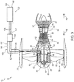
- Figs. 3-4 and 7-8 are less schematic cross-sectional views illustrating examples of hybrid turbine engines 20, according to the present disclosure.
- Fig. 5 is a front view of the hybrid turbine engine of Fig. 4
- Fig. 6 is a cross-sectional view of a portion of the hybrid turbine engine of Figs. 4-5 taken along line 6-6 of Fig. 4 .
- hybrid turbine engines 20 include a first thrust-generating device 30, which includes a turbine 32 that includes a turbine rotary shaft 34.
- Hybrid turbine engines 20 also include a clutch 50 including a clutch input 52, which is operatively coupled to turbine rotary shaft 34, and a clutch output 54.
- Clutch 50 defines a plurality of operational states including at least an engaged state, wherein the clutch input is rotationally coupled to the clutch output, and a disengaged state, wherein the clutch input is rotationally decoupled from the clutch output.
- Hybrid turbine engines 20 further include a rotary electric machine 60, which includes a machine rotary shaft 62 that is operatively coupled to clutch output 54.
- Hybrid turbine engines 20 also include a second thrust-generating device 80, which is operatively coupled to machine rotary shaft 62, and electric power system 100.
- first thrust-generating device 30 and/or turbine 32 thereof may be utilized to provide a motive force for rotation of turbine rotary shaft 34.
- clutch 50 may be utilized to selectively and rotationally engage, or disengage, turbine rotary shaft 34 and machine rotary shaft 62, thereby selectively providing a motive force for rotation of machine rotary shaft 62.
- rotary electric machine 60 may, or may be configured to, selectively receive an electric power input 105 from electric power system 100. Responsive to receipt of electric power input 105, rotary electric machine 60 may produce and/or generate an output torque that rotates second thrust-generating device 80 via machine rotary shaft 62. Stated another way, electric power system 100 may be utilized to power second thrust-generating device 80 via rotary electric machine 60. Stated yet another way, and responsive to receipt of electric power input 105, rotary electric machine 60 may be utilized to power second thrust-generating device 80. This powering of second thrust-generating device 80 may supplement first thrust-generating device 30, such as when clutch 50 is in the engaged state. Alternatively, this powering of second thrust-generating device 80 may be independent of first thrust-generating device 30, such as when clutch 50 is in the disengaged state.
- Rotary electric machine 60 also may, or may be configured to, selectively receive an input torque from machine rotary shaft 62. Responsive to receipt of the input torque, rotary electric machine 60 may produce and/or generate an electric power output 107, which may be provided to electric power system 100. Stated another way, rotary electric machine 60 may be, or may function as, an electric power source, such as a generator and/or an alternator, that may be utilized to charge, or to recharge, electric power system 100. The generation of electric power output 107 may be powered by first thrust-generating device 30, such as when clutch 50 is in the engaged state and machine rotary shaft 62 receives the input torque from the first thrust-generating device. Additionally or alternatively, the generation of electric power output 107 may be independent of the operation of first thrust-generating device 30, such as when clutch 50 is in the disengaged state and machine rotary shaft 62 receives the input torque from second thrust-generating device 80.
- first thrust-generating device 30 such as when clutch 50 is in the engaged state and machine rotary shaft 62 receives the input torque from
- First thrust-generating device 30 may include any suitable turbine 32, or even a turbine assembly, that includes turbine rotary shaft 34 and/or that is configured to generate a first thrust.
- turbine rotary shaft 34 may be a low-speed turbine rotary shaft 34 that rotates at a low-speed shaft rotational frequency.
- first thrust-generating device 30 also may include a high-speed turbine rotary shaft 36 that rotates at a high-speed shaft rotational frequency. The high-speed shaft rotational frequency may be greater than the low-speed shaft rotational frequency.
- First thrust-generating device 30 also may include a combustion chamber 38, which may be configured to receive and to combust a fuel to power the first thrust-generating device.
- First thrust-generating device 30 further may include a compressor 40, which also may be referred to herein as a low-pressure compressor 40.
- Compressor 40 may be upstream, or positioned in an upstream direction 48, from combustion chamber 38, may be operatively coupled to turbine rotary shaft 34, and/or may be configured to rotate with the turbine rotary shaft.
- First thrust-generating device 30 also may include a turbine 42, which also may be referred to herein as a low-pressure turbine 42.
- Turbine 42 may be downstream, or positioned in a downstream direction 49, from combustion chamber 38, may be operatively coupled to turbine rotary shaft 34, and/or may be configured to rotate with the turbine rotary shaft.
- first thrust-generating device 30 further may include a high-pressure compressor 44.
- High-pressure compressor 44 when present, may be downstream from low-pressure compressor 40, may be upstream from combustion chamber 38, may be operatively coupled to high-speed turbine rotary shaft 36, and/or may be configured to rotate with the high-speed turbine rotary shaft.
- first thrust-generating device 30 also may include a high-pressure turbine 46.
- High-pressure turbine 46 when present, may be downstream from combustion chamber 38, may be upstream from low-pressure turbine 42, may be operatively coupled to high-speed turbine rotary shaft 36, and/or may be configured to rotate with the high-speed turbine rotary shaft.
- Second thrust-generating device 80 may include any suitable structure that may be operatively coupled to machine rotary shaft 62 and/or that may be configured to generate a second thrust that is independent of the first thrust generated by first thrust-generating device 30.
- Examples of second thrust-generating device 80 include a fan 82, as illustrated in Figs. 2-6 , and/or a propeller 84, as illustrated in Figs. 2 and 7-8 .
- Fan 82 when present, may include a plurality of fan blades 83.
- Propeller 84 when present, may include a plurality of propeller blades 85.
- hybrid turbine engine 20 When second thrust-generating device 80 includes fan 82, hybrid turbine engine 20 also may be referred to herein as a turbofan hybrid turbine engine, as a hybrid turbofan engine, and/or as a turbofan engine.
- hybrid turbine engine 20 When second thrust-generating device 80 includes propeller 84, hybrid turbine engine 20 also may be referred to herein as a turboprop hybrid turbine engine, as a hybrid turboprop engine, and/or as a turboprop engine.
- Clutch 50 may include any suitable structure that may be adapted, configured, designed, and/or constructed to include clutch input 52 and clutch output 54, as illustrated in Fig. 2 , and/or to define at least the engaged state and the disengaged state.
- clutch 50 include an overrunning clutch, a one-way clutch, a one-way tapered clutch, a tooth clutch, and/or a synchronized clutch.
- hybrid turbine engine 20 and/or clutch 50 thereof may include a synchronization structure 56.
- Synchronization structure 56 when present, may be configured to synchronize clutch input 52 and clutch output 54, such as to permit clutch 50 to transition from the disengaged state to the engaged state and/or from the engaged state to the disengaged state while clutch input 52 and/or clutch output 54 rotates.
- An example of synchronization structure 56 includes a speed controller 57 configured to control a rotational frequency of rotary electric machine 60 to synchronize the clutch output to the clutch input. This may include synchronization of clutch output 54 to clutch input 52 to the same, or similar, respective rotational frequencies, such as to permit and/or facilitate low-friction engagement and/or disengagement of clutch 50 at any suitable synchronized rotational frequency.
- clutch 50 may include and/or be an automatic, or an automatically actuated, clutch 50.
- Such an automatic clutch 50 may be configured to automatically rotationally couple clutch input 52 to clutch output 54 when a clutch input rotational frequency of the clutch input is greater than a clutch output rotational frequency of the clutch output.
- Such an automatic clutch 50 additionally or alternatively may be configured to automatically rotational decouple clutch input 52 from clutch output 54 when the clutch input rotational frequency is less than the clutch output rotational frequency.
- clutch 50 may include and/or be a selectively actuated clutch 50.
- a selectively actuated clutch 50 may be configured to be selectively actuated between the engaged state and the disengaged state, such as by an operator, or by a control system, of hybrid turbine engine 20. This may be accomplished in any suitable manner.
- clutch 50 may include an engagement structure 58 configured to selectively transition the clutch between the engaged state and the disengaged state.
- engagement structure 58 include an actuator, a lever, an electrically actuated engagement structure, a mechanically actuated engagement structure, and/or a hydraulically actuated engagement structure.
- Rotary electric machine 60 may include any suitable structure that may include machine rotary shaft 62, that may be configured to receive electric power input 105 and to generate the output torque therefrom, and/or that may be configured to receive the input torque and to generate electric power output 107 therefrom.
- rotary electric machine 60 may include and/or be a generator, an alternator, an electric motor, and/or a permanent magnet brushless alternating current (AC) asynchronous axial electric machine.
- AC permanent magnet brushless alternating current
- rotary electric machine 60 may include a rotor 64, as illustrated in Figs. 2-8 .
- Rotor 64 when present, may be operatively attached to and/or may rotate with machine rotary shaft 62 and/or second thrust-generating device 80.
- rotary electric machine 60 may include a stator 68.
- Stator 68 when present, may be operatively attached to an engine case structure 22 of hybrid turbine engine 20.
- machine rotary shaft 62 may be aligned, or axially aligned with turbine rotary shaft 34, as illustrated in Figs. 2-4 .
- machine rotary shaft 62 may be offset, or axially offset, from turbine rotary shaft 34, as illustrated in Figs. 7-8 .
- Machine rotary shaft 62 may be parallel, or at least substantially parallel, to turbine rotary shaft 34.
- second thrust-generating device 80 may include a central hub 86. As illustrated in Figs. 2-3 and 7-8 , at least a portion of rotary electric machine 60 may be internal to, located within, operatively attached to, and/or defined by the central hub. Such a rotary electric machine may be referred to herein as a hub-drive rotary electric machine 61.
- stator 68 of rotary electric machine 60 may be internal to central hub 86.
- stator 68 may include a field coil 70 that may be operatively attached to engine case structure 22 and that also may be internal to central hub 86.
- stator 68 may define a central opening 69, and machine rotary shaft 62 may extend within and/or through the central opening.
- Forward bearing 24 may be forward of, or in upstream direction 48 from, at least a portion of rotary electric machine 60 and/or second thrust-generating device 80 and may be configured to support, or may support, machine rotary shaft 62 and/or central hub 86 on a front, forward, or upstream side of stator 68.
- Hybrid turbine engine 20 further may include an aft bearing 26, which also may support central hub 86, such as on an aft side of the central hub.
- rotary electric machine 60 may include rotor 64, and rotor 64 may be configured to rotate relative to stator 68.
- rotor 64 may include a plurality of magnets 65, which may be operatively attached to central hub 86. Magnets 65, when present, may be positioned between stator 68 and central hub 86, as illustrated. Stated another way, magnets 65 may be internal to, or located within, central hub 86.
- fan 82 when second thrust-generating device 80 includes fan 82, fan 82 may include fan blades 83 that may be operatively attached to and/or may extend from central hub 86.
- Magnets 65 when present, may be operatively attached to and/or may extend from the periphery of fan blades 83 and in positional alignment with stator 68, as illustrated in Figs. 4-6 . Stated another way, magnets 65 may be internal to, or located within, fan blade 83 at the peripheral extremity of the fan blade that is opposite central hub 86.
- propeller 84 when second thrust-generating device 80 includes prop, or propeller, 84, propeller 84 may include propeller blades 85 that may be operatively attached to and/or may extend from central hub 86.
- Hybrid turbine engines 20 also may include a pitch control device 28.
- Pitch control device 28 when present, may be configured to adjust a pitch of fan blades 83 and/or of propeller blades 85.
- pitch control device 28 may be configured to rotate fan blades 83 and/or propeller blades 85 relative to central hub 86 and/or about an elongate axis thereof. At least a portion of pitch control device 28 may be operatively attached to and/or configured to rotate with central hub 86.
- rotary electric machine 60 in the form of a ring drive rotary electric machine 72
- engine case structure 22 may surround at least a portion of second thrust-generating device 80, such as an outer periphery region 88 of the second thrust-generating device.
- second thrust-generating device 80 such as an outer periphery region 88 of the second thrust-generating device.
- at least a portion of rotary electric machine 60 may be operatively attached to outer periphery region 88 and/or to the portion of case structure 22 that surrounds outer periphery region 88.
- stator 68 of rotary electric machine 60 may be operatively attached to engine case structure 22, or to the portion of engine case structure 22 that surrounds outer periphery region 88.
- field coil 70 of stator 68 may be operatively attached to the portion of engine case structure 22 that surrounds outer periphery region 88.
- rotor 64 of rotary electric machine 60 may be operatively attached to outer periphery region 88.
- second thrust-generating device 80 includes fan 82
- rotor 64 may be operatively attached to outer periphery region 88 of fan blades 83.
- second thrust-generating device 80 and/or ring drive rotary electric machine 72 further may include a stabilization ring 90, as perhaps best illustrated in Figs. 2 and 6 .
- Stabilization ring 90 when present, may be operatively interconnect fan blades 83, a tip region of fan blades 83, and/or outer periphery region 88 of fan blades 83, such as to stabilize fan blades 83 relative to one another and/or to resist the additional forces generated by the presence of ring drive rotary electric machine 72.
- clutch input 52 may be directly, or directly and operatively, coupled to turbine rotary shaft 34.
- clutch output 54 may be directly, or directly and operatively, coupled to machine rotary shaft 62.
- one or more structures may extend between, or operatively couple, clutch input 52 to turbine rotary shaft 34. Additionally or alternatively, one or more structures may extend between, or operatively couple, clutch output 54 to machine rotary shaft 62.
- hybrid turbine engine 20 may include a gear box 110.
- Gear box 110 when present, may be positioned between first thrust-generating device 30 and second thrust-generating device 80 and/or between turbine rotary shaft 34 and machine rotary shaft 62. In such a configuration, gear box 110 may be configured to provide a predetermined rotational frequency ratio between the turbine rotary shaft and the machine rotary shaft when clutch 50 is in the engaged state.
- hybrid turbine engine 20 includes second thrust-generating device 80 in the form of propeller 84 (i.e., when the hybrid turbine engine is the turboprop hybrid turbine engine), it may be desirable to decrease a rotational frequency of machine rotary shaft 62 when compared to turbine rotary shaft 34.
- gear box 110 may be positioned between, or may operatively couple, turbine rotary shaft 34 and clutch 50. Stated another way, clutch input 52 may be operatively coupled to turbine rotary shaft 34 via gear box 110. Such a configuration is illustrated schematically in Fig. 1 and less schematically in Fig. 8 . Under these conditions, gear box 110 may include a gear box input 112, which may be operatively coupled, or directly operatively coupled, to turbine rotary shaft 34. In addition, gear box 110 may include an output stub shaft 118, which may be operatively coupled, or directly operatively coupled, to clutch input 52.
- gear box 110 may be positioned between, or may operatively couple, clutch 50 and machine rotary shaft 62. Stated another way, clutch output 54 may be operatively coupled to machine rotary shaft 62 via gear box 110. Such a configuration is illustrated schematically in Fig. 2 and less schematically in Fig. 7 . Under these conditions, gear box 110 may include an input stub shaft 116, which may be operatively coupled, or directly operatively coupled, to clutch output 54. In addition, gear box 110 may include a gear box output 114, which may be operatively coupled, or directly operatively coupled, to machine rotary shaft 62.
- hybrid turbine engine 20 includes electric power system 100.
- Electric power system 100 may include any suitable structure that may be configured to provide electric power input 105 to rotary electric machine 60 and also to receive electric power output 107 from the rotary electric machine.
- electric power system 100 may include an energy storage device 102 that may be configured to provide electric power input 105 to rotary electric machine 60 and also to receive electric power output 107 from the rotary electric machine.
- Energy storage device 102 may include any suitable structure that may be configured to selectively store and/or provide electric current.
- An example of energy storage device 102 includes a battery 104.
- electric power system 100 also may include a power supply conduit 106.
- Power supply conduit 106 may extend between energy storage device 102 and rotary electric machine 60, may be configured to convey electric power input 105 from energy storage device 102 and/or to rotary electric machine 60, or to stator 68, and/or may be configured to convey electric power output 107 from rotary electric machine 60, or from stator 68, and/or to energy storage device 102.
- Examples of power supply conduit 106 include at least one electrical conductor, at least one wire, at least one insulated wire, and/or at least one electrical wire.
- electric power system 100 further may include a power conditioner 108, which also may be referred to herein as an electric power converter 108.
- Power conditioner 108 when present, may be configured to receive an unconditioned electric power input 125 from energy storage device 102, to condition the unconditioned electric power input to produce and/or generate a conditioned electric power input 135, and/or to provide the conditioned electric power input to rotary electric machine 60.
- power conditioner 108 may be configured to receive an unconditioned electric power output 127 from rotary electric machine 60, to condition the unconditioned electric power output to produce and/or generate a conditioned electric power output 137, and/or to provide the conditioned electric power output to energy storage device 102.
- An example of unconditioned electric power input 125 includes a direct current (DC) unconditioned electric power input.
- Examples of conditioned electric power input 135 include an alternating current (AC) conditioned electric power input, a single phase AC conditioned electric power input, and/or a three phase AC conditioned electric power input.
- Examples of unconditioned electric power output 127 include an alternating current (AC) unconditioned electric power output, a single phase AC unconditioned electric power output, and/or a three phase AC unconditioned electric power output.
- An example of conditioned electric power output 137 includes a DC conditioned electric power output.
- Fig. 9 is a flowchart depicting methods 200, according to the present disclosure, of operating a hybrid turbine engine, such as hybrid turbine engine 20 of Figs. 1-8 and/or aircraft 10 that includes hybrid turbine engine 20.
- Methods 200 include combusting a fuel at 210 and may include transitioning a clutch at 220.
- Methods 200 also include selectively providing an electric power input at 230 and selectively receiving an input torque at 240.
- Methods 200 further may include accelerating an aircraft at 250, decelerating the aircraft at 260, descending the aircraft at 270, cruising the aircraft at 280, and/or starting the aircraft at 290.
- Combusting the fuel at 210 may include combusting the fuel within a turbine of a first thrust-generating device. This may include combusting to rotate a turbine rotary shaft of the first thrust-generating device at a turbine rotary shaft rotational frequency.
- the turbine rotary shaft is operatively coupled to a clutch input of a clutch.
- the clutch also includes a clutch output, which is operatively coupled to a machine rotary shaft of a rotary electric machine.
- the machine rotary shaft rotates at a machine rotary shaft rotational frequency, and a second thrust-generating device is operatively coupled to the machine rotary shaft.
- Examples of the first thrust-generating device are disclosed herein with reference to first thrust-generating device 30 of Figs. 2-4 and 7-8 .
- Examples of the turbine rotary shaft are disclosed herein with reference to turbine rotary shaft 34 of Figs. 2-4 and 7-8 .
- Examples of the clutch are disclosed herein with reference to clutch 50 of Figs. 2-4 and 7-8 .
- Examples of the rotary electric machine are disclosed herein with reference to rotary electric machine 60 of Figs. 2-4 and 7-8 .
- Examples of the second thrust-generating device are disclosed herein with reference to second thrust-generating device 80 of Figs. 2-4 and 7-8 .
- Transitioning the clutch at 220 may include transitioning the clutch between an engaged state, in which the clutch input is rotationally coupled to the clutch output, and a disengaged state, in which the clutch input is rotationally decoupled from the clutch output.
- the transitioning at 220 may include transitioning in any suitable manner and/or based upon any suitable criteria.
- the transitioning at 220 may include transitioning based upon an operational state of an aircraft that includes the hybrid turbine engine.
- the transitioning at 220 may include transitioning to the engaged state when the turbine shaft rotational frequency is at least as great as the machine rotary shaft frequency.
- Such a configuration may permit and/or to facilitate powering of the second thrust-generating device by the first thrust-generating device. Additionally or alternatively, such a configuration may permit and/or facilitate applying the input torque to the rotary electric machine with the first thrust-generating device.
- the transitioning at 220 may include transitioning to the disengaged state when the turbine rotary shaft rotational frequency is less than the machine rotary shaft rotational frequency.
- Such a configuration may permit and/or facilitate powering of the second thrust-generating device, with the rotary electric machine, independent of the first thrust-generating device. Additionally or alternatively, such a configuration may permit application of the input torque by the second thrust-generating device, as discussed in more detail herein.
- Selectively providing the electric power input at 230 may include selectively providing the electric power input to the rotary electric machine, with an electric power system, and generating, at 235, an output torque that rotates the machine rotary shaft and the second thrust-generating device.
- the output torque may be generated by the rotary electric machine responsive to receipt of the electric power input by the rotary electric machine.
- Selectively receiving the input torque at 240 may include selectively receiving the input torque, from the second thrust-generating device, with the rotary electric machine, generating, at 245, an electric power output, and providing the electric power output to the electric power system.
- the electric power output may be generated, by the rotary electric machine, responsive to receipt of the input torque.
- the hybrid turbine engine may be operatively attached to an aircraft, and accelerating the aircraft at 250 may include accelerating the aircraft with, via, and/or utilizing the hybrid turbine engine.
- the accelerating at 250 may be performed during takeoff and/or climb of the aircraft.
- the accelerating at 250 may be performed while the clutch is in the engaged state, such as may be accomplished during the transitioning at 220, during the combusting at 210, and during the selectively providing at 230.
- the second thrust-generating device 80 of the hybrid turbine engine may be powered by both the first thrust-generating device 30, such as via performing the combusting at 210 in a high thrust output state, and by the electric power system 100, such as via the providing at 230.
- Such a configuration may permit hybrid turbine engines, according to the present disclosure, to produce a greater amount of overall thrust and/or to have a smaller first thrust-generating device (e.g., turbine) when compared to turbine engines that perform the combusting at 210 but do not perform the transitioning at 220 and the selectively providing at 230.
- first thrust-generating device e.g., turbine
- the accelerating at 250 may be performed while the clutch is in the disengaged state, such as may be accomplished during the transitioning at 220, and during the selectively providing at 230.
- the combusting at 210 may include combusting in a low fuel burn state, an idle state, and/or a low thrust output state, such as to decrease fuel consumption of the first thrust-generating device, and the accelerating at 250 may be accomplished, or powered, primarily, or even solely via the second thrust-generating device 80 by the electric power system 100.
- Decelerating the aircraft at 260 may include decelerating that aircraft with, via, and/or utilizing the hybrid turbine engine.
- the decelerating at 260 may be performed, for example, during descent and/or landing of the aircraft.
- the decelerating at 260 may include decreasing a kinetic energy of the aircraft.
- the decelerating at 260 may be performed while the clutch is in the disengaged state, such as may be accomplished during the transitioning at 220.
- the combusting at 210 may include combusting in the low fuel burn state, the idle state, and/or the low thrust output state, such as to decrease fuel consumption of the first thrust-generating device 30.
- air flow through the second thrust-generating device 80 may rotate the second thrust-generating device, thereby providing a motive force for the selectively receiving at 240.
- the selectively receiving at 240 may be performed during, or concurrently with, the decelerating at 260, such as to facilitate the generating at 245 and/or to charge, or recharge, the electric power system 100.
- a portion of the kinetic energy of the aircraft, which is decreased during the decelerating at 260 may be converted, via the second thrust-generating device and the rotary electric machine, to electrical energy, which may be stored by the electric power system. This may increase an overall efficiency of the aircraft and/or of the hybrid turbine jet engine that powers the aircraft.
- Such a configuration may be referred to herein as windmill brake mode.
- the selectively providing at 230 may be utilized to generate a reverse-thrust with the second thrust-generating device 80.
- a reverse thrust may be generated by rotating the second thrust-generating device 80 in a reverse-thrust direction and/or by deploying a thrust reverser assembly of the hybrid turbine engine and rotating the second thrust-generating device 80 in a forward-thrust direction.
- the forward-thrust direction may be a rotational direction, such as one of clockwise and counterclockwise, that generates a forward thrust that urges the aircraft forward.
- the reverse-thrust direction may be a rotational direction, such as the other of clockwise and counterclockwise, that generates a reverse thrust that urges the aircraft backward.
- Descending the aircraft at 270 may include decreasing an altitude of the aircraft and/or decreasing a distance between the aircraft and a ground surface that is below the aircraft.
- the descending at 270 may include decreasing a potential energy, or a gravitational potential energy, of the aircraft, such as via the decrease between the aircraft and the ground surface.
- the descending at 260 may be performed while the clutch is in the disengaged state, such as may be accomplished during the transitioning at 220.
- the combusting at 210 may include combusting in the low fuel burn state, the idle state, and/or the low thrust output state, such as to decrease fuel consumption of the first thrust-generating device 30.
- air flow through the second thrust-generating device 80 may rotate the second thrust-generating device, thereby providing a motive force for the selectively receiving at 240.
- the selectively receiving at 240 may be performed during, or concurrently with, the descending at 270, such as to facilitate the generating at 245 and/or to charge, or recharge, the electric power system 100.
- a portion of the potential energy of the aircraft, which is decreased during the descending at 270 may be converted, via the second thrust-generating device and the rotary electric machine, to electrical energy, which may be stored by the electric power system. This may increase an overall efficiency of the aircraft and/or of the hybrid turbine jet engine that powers the aircraft.
- Such a configuration may be referred to herein as windmill power generation mode.
- Cruising the aircraft at 280 may include cruising the aircraft at a constant, or at least substantially constant, velocity and/or altitude.
- Methods 200 may include performing the combusting at 210 while the clutch is in the engaged state and during the cruising at 280, such as to power both the second thrust-generating device 80 with the first thrust-generating device 30. Additionally or alternatively, methods 200 may include performing the selectively receiving at 240 during the cruising at 280, such as to provide the electric power output (as a result of the generating at 245) to the electric power system and/or to charge the electric power system. Stated another way, and during the cruising at 280, the first thrust-generating device 30 may be utilized to provide a motive force for the selectively receiving at 240.
- Starting the aircraft at 290 may include starting the aircraft with, via, and/or utilizing the rotary electric machine 60. This may include performing the selectively receiving at 240 while the clutch is in the engaged state to rotate the turbine rotary shaft with the rotary electric machine 60 and/or to permit, facilitate, and/or initiate the combusting at 210.
- Fig. 10 is a chart illustrating examples of operational modes of a hybrid turbine engine, such as hybrid turbine engine 20 of Figs. 1-8 , and/or of an aircraft that includes the hybrid turbine engine. These operational modes are illustrated in the form of an altitude vs. time plot.
- an aircraft initially may be on the ground and/or may be in an idle state on the ground, such as for times that are less than time t 0 .
- the hybrid turbine engine may be off, may not be running, and/or may not be consuming fuel.
- the hybrid turbine engine may be started, such as is described herein with reference to the starting at 290 of Fig. 9 .
- the hybrid turbine engine may be referred to herein as running and/or as being in a running state.
- the aircraft may initiate take-off, such as from time t 0 to time t 1 in Fig. 10 .
- take-off the aircraft may be accelerated utilizing the hybrid turbine engine. This may include acceleration that is facilitated utilizing first thrust-generating device 30 and/or utilizing second thrust-generating device 80 of Figs. 2-8 .
- second thrust-generating device 80 may be sized to provide sufficient thrust for take-off alone and/or without being supplemented by first thrust-generating device 30.
- first thrust-generating device 30 may be in the idle state, and electric power system 100 may be utilized to provide electric power input 105 to rotary electric machine 60, such as is described herein with reference to the selectively providing at 230 of Fig. 9 .
- the rotary electric machine may produce and/or generate the output torque, which may power second thrust-generating device 80, as described herein with reference to the generating at 235 of Fig. 9 .
- Second thrust-generating device 80 then may generate a thrust that is sufficient to accelerate the aircraft for take-off.
- clutch 50 may be in the disengaged state during take-off of the aircraft.
- first thrust-generating device 30 and second thrust-generating device 80 together, or cooperatively, may be utilized to accelerate the aircraft for take-off.
- clutch 50 may be in the engaged state and both the first thrust-generating device and the second thrust-generating device may be utilized to generate thrust, such as via simultaneously performing the combusting at 210, the providing at 230, and the generating at 235 of Fig. 9 .
- first thrust-generating device 30 may be utilized alone, second thrust-generating device 80 may be utilized alone, and/or the first thrust-generating device and the second thrust-generating device may be utilized concurrently and/or cooperatively.
- first thrust-generating device and the second thrust-generating device may be utilized concurrently and/or cooperatively, and the clutch may be in the engaged state.
- first thrust-generating device may be utilized alone, and the clutch may be in the disengaged state.
- second thrust-generating device may be utilized alone, and the clutch may be in the disengaged state.
- the first thrust-generating device and the second thrust-generating device may be utilized at least partially sequentially. Under these conditions, the first thrust-generating device and the second thrust-generating device initially may be utilized concurrently, with the clutch in the engaged state, to provide maximum thrust, as illustrated between times t 1 and t 2 . Once a threshold speed and/or altitude is reached, the second thrust-generating device may be utilized alone, with the clutch in the disengaged sate, such as is illustrated between times t 2 and t 3 . Such a configuration may provide the high acceleration that may be needed for take-off and initial climb while, at the same time, decreasing overall fuel consumption.
- first thrust-generating device 30 may be utilized alone to provide thrust sufficient to maintain the altitude and/or speed of the aircraft.
- the clutch may be in the engaged state and the first thrust-generating device may provide the input torque to the second thrust-generating device and/or to the rotary electric machine, thereby facilitating generation of the output electric current by the rotary electric machine and permitting charging of the electric power system.
- the second thrust-generating device may be utilized to provide additional thrust, such as to supplement the first thrust-generating device or in place of the first thrust-generating device. This may permit the altitude increase to be achieved while, at the same time, permitting the first thrust-generating device to remain in an efficient operating regime. Cruise operation them may be continued, as illustrated in Fig. 10 between times t 5 and t 6 .
- the clutch may be disengaged and the first thrust-generating device may be in the idle, or low fuel consumption, state.
- the second thrust-generating device may receive the input torque due to the decrease in speed and/or altitude, and the corresponding decrease in kinetic and/or potential energy, respectively, thereby permitting generation of the electric power output and facilitating charging, or recharging, of the electric power system.
- the hybrid turbine engine may be utilized increase the speed and/or altitude of the aircraft. This may be accomplished as described herein with reference to the climb between times t 1 and t 3 .
- additional deceleration may be needed.
- This additional deceleration may be accomplished utilizing a conventional thrust reverse assembly, with the thrust being provided by the first thrust-generating device and/or by the second thrust-generating device.
- the hybrid turbine engine may not include a conventional thrust reverse assembly.
- rotation of the second thrust-generating device may be reversed (i.e., the rotary electric machine may be driven in reverse) to generate the reverse thrust.
- Such a configuration may permit generation of reverse thrust without increasing, or even utilizing, thrust generated by the first thrust-generating device.
- the terms “adapted” and “configured” mean that the element, component, or other subject matter is designed and/or intended to perform a given function. Thus, the use of the terms “adapted” and “configured” should not be construed to mean that a given element, component, or other subject matter is simply “capable of” performing a given function but that the element, component, and/or other subject matter is specifically selected, created, implemented, utilized, programmed, and/or designed for the purpose of performing the function. It is also within the scope of the present disclosure that elements, components, and/or other recited subject matter that is recited as being adapted to perform a particular function may additionally or alternatively be described as being configured to perform that function, and vice versa. Similarly, subject matter that is recited as being configured to perform a particular function may additionally or alternatively be described as being operative to perform that function.
- the phrase "at least one,” in reference to a list of one or more entities should be understood to mean at least one entity selected from any one or more of the entity in the list of entities, but not necessarily including at least one of each and every entity specifically listed within the list of entities and not excluding any combinations of entities in the list of entities.
- This definition also allows that entities may optionally be present other than the entities specifically identified within the list of entities to which the phrase "at least one" refers, whether related or unrelated to those entities specifically identified.
- At least one of A and B may refer, in one embodiment, to at least one, optionally including more than one, A, with no B present (and optionally including entities other than B); in another embodiment, to at least one, optionally including more than one, B, with no A present (and optionally including entities other than A); in yet another embodiment, to at least one, optionally including more than one, A, and at least one, optionally including more than one, B (and optionally including other entities).
- each of the expressions “at least one of A, B and C,” “at least one of A, B, or C,” “one or more of A, B, and C,” “one or more of A, B, or C” and “A, B, and/or C” may mean A alone, B alone, C alone, A and B together, A and C together, B and C together, A, B and C together, and optionally any of the above in combination with at least one other entity.
- the phrase, "for example,” the phrase, “as an example,” and/or simply the term “example,” when used with reference to one or more components, features, details, structures, embodiments, and/or methods according to the present disclosure, are intended to convey that the described component, feature, detail, structure, embodiment, and/or method is an illustrative, non-exclusive example of components, features, details, structures, embodiments, and/or methods according to the present disclosure.
Landscapes
- Engineering & Computer Science (AREA)
- Mechanical Engineering (AREA)
- Chemical & Material Sciences (AREA)
- Combustion & Propulsion (AREA)
- General Engineering & Computer Science (AREA)
- Aviation & Aerospace Engineering (AREA)
- Power Engineering (AREA)
- Connection Of Motors, Electrical Generators, Mechanical Devices, And The Like (AREA)
Applications Claiming Priority (1)
| Application Number | Priority Date | Filing Date | Title |
|---|---|---|---|
| US15/904,838 US10378452B1 (en) | 2018-02-26 | 2018-02-26 | Hybrid turbine jet engines and methods of operating the same |
Publications (2)
| Publication Number | Publication Date |
|---|---|
| EP3530928A1 true EP3530928A1 (de) | 2019-08-28 |
| EP3530928B1 EP3530928B1 (de) | 2021-09-22 |
Family
ID=64746066
Family Applications (1)
| Application Number | Title | Priority Date | Filing Date |
|---|---|---|---|
| EP18213871.9A Active EP3530928B1 (de) | 2018-02-26 | 2018-12-19 | Hybridturbinenstrahltriebwerk und verfahren zum betrieb davon |
Country Status (3)
| Country | Link |
|---|---|
| US (1) | US10378452B1 (de) |
| EP (1) | EP3530928B1 (de) |
| CN (1) | CN110195656B (de) |
Cited By (4)
| Publication number | Priority date | Publication date | Assignee | Title |
|---|---|---|---|---|
| EP3798129A1 (de) * | 2019-09-30 | 2021-03-31 | Ratier-Figeac SAS | Elektromotor für einen propellerantrieb |
| EP3835557A1 (de) * | 2019-12-12 | 2021-06-16 | Rolls-Royce plc | Hybridantriebssystem für flugzeuge |
| GB2607305A (en) * | 2021-06-01 | 2022-12-07 | Bae Systems Plc | Propulsion system |
| EP4098862A1 (de) * | 2021-06-01 | 2022-12-07 | BAE SYSTEMS plc | Antriebssystem |
Families Citing this family (19)
| Publication number | Priority date | Publication date | Assignee | Title |
|---|---|---|---|---|
| FR3057120B1 (fr) * | 2016-10-03 | 2023-03-17 | Safran Helicopter Engines | Machine electrique pour turbopropulseur d'aeronef |
| US10352189B2 (en) * | 2017-05-10 | 2019-07-16 | Pratt & Whitney Canada Corp. | Method and system for setting an acceleration schedule for engine start |
| US11414175B2 (en) | 2019-04-01 | 2022-08-16 | Pratt & Whitney Canada Corp. | Method and system for operating an aircraft powerplant |
| WO2020208402A1 (en) * | 2019-04-11 | 2020-10-15 | Pilatus Flugzeugwerke Ag | Conformal energy bay |
| US11401824B2 (en) | 2019-10-15 | 2022-08-02 | General Electric Company | Gas turbine engine outlet guide vane assembly |
| US11286795B2 (en) | 2019-10-15 | 2022-03-29 | General Electric Company | Mount for an airfoil |
| CN112660396A (zh) | 2019-10-15 | 2021-04-16 | 通用电气公司 | 用于飞行器的可去除机身护罩 |
| US11834196B2 (en) | 2019-10-15 | 2023-12-05 | General Electric Company | System and method for control for unducted engine |
| US11506067B2 (en) | 2019-10-15 | 2022-11-22 | General Electric Company | Gas turbine engine with clutch assembly |
| US10941707B1 (en) | 2019-10-18 | 2021-03-09 | The Boeing Company | Hybrid turbine engines, aircraft including the same, and associated methods |
| US11203439B2 (en) | 2019-10-18 | 2021-12-21 | The Boeing Company | Rotary electric engines, aircraft including the same, and associated methods |
| CN111997761B (zh) * | 2020-08-25 | 2022-12-20 | 中国航空工业集团公司沈阳飞机设计研究所 | 一种提高航空发动机高原起动成功率的方法及系统 |
| FR3115812B1 (fr) * | 2020-10-29 | 2023-09-08 | Safran Helicopter Engines | Turbogénérateur à turbine libre comprenant une machine électrique réversible couplée à la turbine libre |
| US11738875B2 (en) * | 2020-12-11 | 2023-08-29 | Launch Point Electric Propulsion Solutions, Inc. | Lightweight, high-efficiency, energy-dense, hybrid power system for reliable electric flight |
| CA3145956A1 (en) * | 2021-03-15 | 2022-09-15 | The Boeing Company | Method and system for operating a variable frequency independent speed motor in an extended speed range |
| FR3123093B1 (fr) * | 2021-05-18 | 2023-06-09 | Safran | Procédé d’inversion de poussée pour soufflante aéronautique |
| US20230096526A1 (en) * | 2021-09-24 | 2023-03-30 | Pratt & Whitney Canada Corp. | Aircraft power plant with a transmission to drive an electrical machine |
| WO2023137230A2 (en) * | 2022-01-14 | 2023-07-20 | Verdego Aero, Inc. | Parallel hybrid powerplant with turbofan engine core |
| WO2023211278A1 (en) * | 2022-04-27 | 2023-11-02 | Verdego Aero, Inc. | Hybrid turbofan engine with a planetary gearset for blending power between an electric output and variable-thrust bypass fan |
Citations (6)
| Publication number | Priority date | Publication date | Assignee | Title |
|---|---|---|---|---|
| US20100107652A1 (en) * | 2008-10-08 | 2010-05-06 | Searete Llc, A Limited Liability Corporation Of The State Of Delaware | Hybrid propulsive engine including at least one independently rotatable compressor rotor |
| WO2010067172A2 (en) * | 2008-12-12 | 2010-06-17 | Norbert Bayer | Apparatus and method for energy recovery on jet-powered airplanes on approach for landing |
| US20100327109A1 (en) * | 2005-11-09 | 2010-12-30 | Pratt & Whitney Canada Corp. | Method and system for taxiing an aircraft |
| US20160363050A1 (en) * | 2015-06-10 | 2016-12-15 | General Electric Company | Pitch change mechanism for shrouded fan with low fan pressure ratio |
| US20180003072A1 (en) * | 2016-07-01 | 2018-01-04 | United Technologies Corporation | Descent operation for an aircraft parallel hybrid gas turbine electric propulsion system |
| EP3335995A1 (de) * | 2016-12-13 | 2018-06-20 | General Electric Company | Hybrid-elektrisches antriebssystem |
Family Cites Families (22)
| Publication number | Priority date | Publication date | Assignee | Title |
|---|---|---|---|---|
| FR2076450A5 (de) * | 1970-01-15 | 1971-10-15 | Snecma | |
| US3940926A (en) * | 1973-08-31 | 1976-03-02 | Craig Alfred C | Jet propulsion engines |
| US4424452A (en) * | 1982-01-19 | 1984-01-03 | Francis Paul T | Fluid-driven power generator |
| GB9910393D0 (en) * | 1999-05-05 | 1999-07-07 | Lucas Ind Plc | Electrical generator,an aero-engine including such a generator and an aircraft including such a generator |
| US20100270802A1 (en) * | 2007-03-23 | 2010-10-28 | Flodesign Wind Turbine Corporation | Wind turbine |
| FR2933910B1 (fr) * | 2008-07-18 | 2010-12-17 | Eurocopter France | Installation motrice hybride et procede de commande d'une telle installation motrice |
| US8109073B2 (en) * | 2008-10-08 | 2012-02-07 | The Invention Science Fund I, Llc | Hybrid propulsive engine including at least one independently rotatable compressor stator |
| GB0903423D0 (en) * | 2009-03-02 | 2009-04-08 | Rolls Royce Plc | Variable drive gas turbine engine |
| US20120068670A1 (en) * | 2009-03-16 | 2012-03-22 | Bersiek Shamel A | Wind jet turbine |
| US8178987B2 (en) * | 2009-05-20 | 2012-05-15 | E-Net, Llc | Wind turbine |
| US20120128493A1 (en) | 2010-11-19 | 2012-05-24 | Shelley Rudolph Allen | Hybrid free-air gas turbine engine |
| US9200592B2 (en) * | 2011-06-28 | 2015-12-01 | United Technologies Corporation | Mechanism for turbine engine start from low spool |
| ITFI20120194A1 (it) * | 2012-10-01 | 2014-04-02 | Nuovo Pignone Srl | "a turbine-driven reciprocating compressor and method" |
| FR2998542B1 (fr) * | 2012-11-26 | 2015-07-17 | Eurocopter France | Procede et aeronef a voilure tournante muni de trois moteurs |
| US10352247B2 (en) * | 2013-02-27 | 2019-07-16 | United Technologies Corporation | Low spool starter system for gas turbine engine |
| FR3003514B1 (fr) * | 2013-03-25 | 2016-11-18 | Eurocopter France | Aeronef a voilure tournante a motorisation hybride. |
| GB201320988D0 (en) * | 2013-11-28 | 2014-01-15 | Rolls Royce Plc | An aircraft |
| US10227137B2 (en) * | 2016-03-22 | 2019-03-12 | Ge Aviation Systems Llc | Hybrid power system for an aircraft |
| US20180003071A1 (en) * | 2016-07-01 | 2018-01-04 | United Technologies Corporation | High efficiency aircraft parallel hybrid gas turbine electric propulsion system |
| US10017266B2 (en) * | 2016-09-22 | 2018-07-10 | Top Flight Technologies, Inc. | Power generation and distribution for vehicle propulsion |
| US10676199B2 (en) * | 2017-06-12 | 2020-06-09 | General Electric Company | Propulsion system for an aircraft |
| US10696416B2 (en) * | 2017-06-30 | 2020-06-30 | General Electric Company | Propulsion system for an aircraft |
-
2018
- 2018-02-26 US US15/904,838 patent/US10378452B1/en active Active
- 2018-12-19 EP EP18213871.9A patent/EP3530928B1/de active Active
-
2019
- 2019-01-03 CN CN201910003967.8A patent/CN110195656B/zh active Active
Patent Citations (6)
| Publication number | Priority date | Publication date | Assignee | Title |
|---|---|---|---|---|
| US20100327109A1 (en) * | 2005-11-09 | 2010-12-30 | Pratt & Whitney Canada Corp. | Method and system for taxiing an aircraft |
| US20100107652A1 (en) * | 2008-10-08 | 2010-05-06 | Searete Llc, A Limited Liability Corporation Of The State Of Delaware | Hybrid propulsive engine including at least one independently rotatable compressor rotor |
| WO2010067172A2 (en) * | 2008-12-12 | 2010-06-17 | Norbert Bayer | Apparatus and method for energy recovery on jet-powered airplanes on approach for landing |
| US20160363050A1 (en) * | 2015-06-10 | 2016-12-15 | General Electric Company | Pitch change mechanism for shrouded fan with low fan pressure ratio |
| US20180003072A1 (en) * | 2016-07-01 | 2018-01-04 | United Technologies Corporation | Descent operation for an aircraft parallel hybrid gas turbine electric propulsion system |
| EP3335995A1 (de) * | 2016-12-13 | 2018-06-20 | General Electric Company | Hybrid-elektrisches antriebssystem |
Cited By (5)
| Publication number | Priority date | Publication date | Assignee | Title |
|---|---|---|---|---|
| EP3798129A1 (de) * | 2019-09-30 | 2021-03-31 | Ratier-Figeac SAS | Elektromotor für einen propellerantrieb |
| EP3835557A1 (de) * | 2019-12-12 | 2021-06-16 | Rolls-Royce plc | Hybridantriebssystem für flugzeuge |
| US11891184B2 (en) | 2019-12-12 | 2024-02-06 | Rolls-Royce Plc | Aircraft hybrid propulsion system |
| GB2607305A (en) * | 2021-06-01 | 2022-12-07 | Bae Systems Plc | Propulsion system |
| EP4098862A1 (de) * | 2021-06-01 | 2022-12-07 | BAE SYSTEMS plc | Antriebssystem |
Also Published As
| Publication number | Publication date |
|---|---|
| US20190264617A1 (en) | 2019-08-29 |
| US10378452B1 (en) | 2019-08-13 |
| CN110195656A (zh) | 2019-09-03 |
| CN110195656B (zh) | 2023-02-21 |
| EP3530928B1 (de) | 2021-09-22 |
Similar Documents
| Publication | Publication Date | Title |
|---|---|---|
| US10378452B1 (en) | Hybrid turbine jet engines and methods of operating the same | |
| EP2985901B1 (de) | Hybrides elektrisches impulsenergieantriebssystem für flugzeug | |
| CA2963776C (en) | Hybrid gas-electric turbine engine | |
| US10131441B2 (en) | Aircraft electrical network | |
| US11149578B2 (en) | Propulsion system for an aircraft | |
| US20200392924A1 (en) | Varying the bypass ratio of a turbofan engine | |
| US20200392859A1 (en) | Limiting spool speeds in a gas turbine engine | |
| EP3832097B1 (de) | Gasturbinentriebwerk | |
| EP3751121B1 (de) | Verbesserung der entschleunigung einer gasturbine | |
| EP3751119A1 (de) | Verringerung des leerlaufs in einer antriebsgasturbine | |
| EP3751116B1 (de) | Erzeugung von elektrischem strom bei hohen schubbedingungen | |
| EP3751118A1 (de) | Verhinderung von pumpen | |
| EP3993206A1 (de) | Stromsystem mit dc-bus aufweisend eine veränderliche spannung | |
| EP3751115A1 (de) | Verbesserung der beschleunigung einer gasturbine | |
| US20230332509A1 (en) | Increasing surge margin and compression efficiency via shaft power transfer | |
| US11384696B2 (en) | Reducing low flight mach number fuel consumption | |
| RU2782719C2 (ru) | Двигательная установка летательного аппарата и летательный аппарат, приводимый в движение такой двигательной установкой, встроенной в заднюю часть фюзеляжа летательного аппарата | |
| US20230246573A1 (en) | Propulsion channel for aircraft | |
| CN112368207A (zh) | 飞行器推进系统以及由装入飞行器机身后部的这种推进系统提供动力的飞行器 |
Legal Events
| Date | Code | Title | Description |
|---|---|---|---|
| PUAI | Public reference made under article 153(3) epc to a published international application that has entered the european phase |
Free format text: ORIGINAL CODE: 0009012 |
|
| STAA | Information on the status of an ep patent application or granted ep patent |
Free format text: STATUS: REQUEST FOR EXAMINATION WAS MADE |
|
| STAA | Information on the status of an ep patent application or granted ep patent |
Free format text: STATUS: EXAMINATION IS IN PROGRESS |
|
| 17P | Request for examination filed |
Effective date: 20181219 |
|
| AK | Designated contracting states |
Kind code of ref document: A1 Designated state(s): AL AT BE BG CH CY CZ DE DK EE ES FI FR GB GR HR HU IE IS IT LI LT LU LV MC MK MT NL NO PL PT RO RS SE SI SK SM TR |
|
| AX | Request for extension of the european patent |
Extension state: BA ME |
|
| 17Q | First examination report despatched |
Effective date: 20190731 |
|
| STAA | Information on the status of an ep patent application or granted ep patent |
Free format text: STATUS: EXAMINATION IS IN PROGRESS |
|
| GRAP | Despatch of communication of intention to grant a patent |
Free format text: ORIGINAL CODE: EPIDOSNIGR1 |
|
| STAA | Information on the status of an ep patent application or granted ep patent |
Free format text: STATUS: GRANT OF PATENT IS INTENDED |
|
| INTG | Intention to grant announced |
Effective date: 20210604 |
|
| GRAS | Grant fee paid |
Free format text: ORIGINAL CODE: EPIDOSNIGR3 |
|
| GRAA | (expected) grant |
Free format text: ORIGINAL CODE: 0009210 |
|
| STAA | Information on the status of an ep patent application or granted ep patent |
Free format text: STATUS: THE PATENT HAS BEEN GRANTED |
|
| AK | Designated contracting states |
Kind code of ref document: B1 Designated state(s): AL AT BE BG CH CY CZ DE DK EE ES FI FR GB GR HR HU IE IS IT LI LT LU LV MC MK MT NL NO PL PT RO RS SE SI SK SM TR |
|
| REG | Reference to a national code |
Ref country code: GB Ref legal event code: FG4D |
|
| REG | Reference to a national code |
Ref country code: DE Ref legal event code: R096 Ref document number: 602018023867 Country of ref document: DE |
|
| REG | Reference to a national code |
Ref country code: IE Ref legal event code: FG4D |
|
| REG | Reference to a national code |
Ref country code: CH Ref legal event code: EP Ref country code: AT Ref legal event code: REF Ref document number: 1432508 Country of ref document: AT Kind code of ref document: T Effective date: 20211015 |
|
| REG | Reference to a national code |
Ref country code: LT Ref legal event code: MG9D |
|
| REG | Reference to a national code |
Ref country code: NL Ref legal event code: MP Effective date: 20210922 |
|
| PG25 | Lapsed in a contracting state [announced via postgrant information from national office to epo] |
Ref country code: BG Free format text: LAPSE BECAUSE OF FAILURE TO SUBMIT A TRANSLATION OF THE DESCRIPTION OR TO PAY THE FEE WITHIN THE PRESCRIBED TIME-LIMIT Effective date: 20211222 Ref country code: LT Free format text: LAPSE BECAUSE OF FAILURE TO SUBMIT A TRANSLATION OF THE DESCRIPTION OR TO PAY THE FEE WITHIN THE PRESCRIBED TIME-LIMIT Effective date: 20210922 Ref country code: NO Free format text: LAPSE BECAUSE OF FAILURE TO SUBMIT A TRANSLATION OF THE DESCRIPTION OR TO PAY THE FEE WITHIN THE PRESCRIBED TIME-LIMIT Effective date: 20211222 Ref country code: SE Free format text: LAPSE BECAUSE OF FAILURE TO SUBMIT A TRANSLATION OF THE DESCRIPTION OR TO PAY THE FEE WITHIN THE PRESCRIBED TIME-LIMIT Effective date: 20210922 Ref country code: RS Free format text: LAPSE BECAUSE OF FAILURE TO SUBMIT A TRANSLATION OF THE DESCRIPTION OR TO PAY THE FEE WITHIN THE PRESCRIBED TIME-LIMIT Effective date: 20210922 Ref country code: HR Free format text: LAPSE BECAUSE OF FAILURE TO SUBMIT A TRANSLATION OF THE DESCRIPTION OR TO PAY THE FEE WITHIN THE PRESCRIBED TIME-LIMIT Effective date: 20210922 Ref country code: FI Free format text: LAPSE BECAUSE OF FAILURE TO SUBMIT A TRANSLATION OF THE DESCRIPTION OR TO PAY THE FEE WITHIN THE PRESCRIBED TIME-LIMIT Effective date: 20210922 |
|
| REG | Reference to a national code |
Ref country code: AT Ref legal event code: MK05 Ref document number: 1432508 Country of ref document: AT Kind code of ref document: T Effective date: 20210922 |
|
| PG25 | Lapsed in a contracting state [announced via postgrant information from national office to epo] |
Ref country code: LV Free format text: LAPSE BECAUSE OF FAILURE TO SUBMIT A TRANSLATION OF THE DESCRIPTION OR TO PAY THE FEE WITHIN THE PRESCRIBED TIME-LIMIT Effective date: 20210922 Ref country code: GR Free format text: LAPSE BECAUSE OF FAILURE TO SUBMIT A TRANSLATION OF THE DESCRIPTION OR TO PAY THE FEE WITHIN THE PRESCRIBED TIME-LIMIT Effective date: 20211223 |
|
| PG25 | Lapsed in a contracting state [announced via postgrant information from national office to epo] |
Ref country code: AT Free format text: LAPSE BECAUSE OF FAILURE TO SUBMIT A TRANSLATION OF THE DESCRIPTION OR TO PAY THE FEE WITHIN THE PRESCRIBED TIME-LIMIT Effective date: 20210922 |
|
| PG25 | Lapsed in a contracting state [announced via postgrant information from national office to epo] |
Ref country code: IS Free format text: LAPSE BECAUSE OF FAILURE TO SUBMIT A TRANSLATION OF THE DESCRIPTION OR TO PAY THE FEE WITHIN THE PRESCRIBED TIME-LIMIT Effective date: 20220122 Ref country code: SK Free format text: LAPSE BECAUSE OF FAILURE TO SUBMIT A TRANSLATION OF THE DESCRIPTION OR TO PAY THE FEE WITHIN THE PRESCRIBED TIME-LIMIT Effective date: 20210922 Ref country code: RO Free format text: LAPSE BECAUSE OF FAILURE TO SUBMIT A TRANSLATION OF THE DESCRIPTION OR TO PAY THE FEE WITHIN THE PRESCRIBED TIME-LIMIT Effective date: 20210922 Ref country code: PT Free format text: LAPSE BECAUSE OF FAILURE TO SUBMIT A TRANSLATION OF THE DESCRIPTION OR TO PAY THE FEE WITHIN THE PRESCRIBED TIME-LIMIT Effective date: 20220124 Ref country code: PL Free format text: LAPSE BECAUSE OF FAILURE TO SUBMIT A TRANSLATION OF THE DESCRIPTION OR TO PAY THE FEE WITHIN THE PRESCRIBED TIME-LIMIT Effective date: 20210922 Ref country code: NL Free format text: LAPSE BECAUSE OF FAILURE TO SUBMIT A TRANSLATION OF THE DESCRIPTION OR TO PAY THE FEE WITHIN THE PRESCRIBED TIME-LIMIT Effective date: 20210922 Ref country code: ES Free format text: LAPSE BECAUSE OF FAILURE TO SUBMIT A TRANSLATION OF THE DESCRIPTION OR TO PAY THE FEE WITHIN THE PRESCRIBED TIME-LIMIT Effective date: 20210922 Ref country code: EE Free format text: LAPSE BECAUSE OF FAILURE TO SUBMIT A TRANSLATION OF THE DESCRIPTION OR TO PAY THE FEE WITHIN THE PRESCRIBED TIME-LIMIT Effective date: 20210922 Ref country code: CZ Free format text: LAPSE BECAUSE OF FAILURE TO SUBMIT A TRANSLATION OF THE DESCRIPTION OR TO PAY THE FEE WITHIN THE PRESCRIBED TIME-LIMIT Effective date: 20210922 Ref country code: AL Free format text: LAPSE BECAUSE OF FAILURE TO SUBMIT A TRANSLATION OF THE DESCRIPTION OR TO PAY THE FEE WITHIN THE PRESCRIBED TIME-LIMIT Effective date: 20210922 |
|
| REG | Reference to a national code |
Ref country code: DE Ref legal event code: R097 Ref document number: 602018023867 Country of ref document: DE |
|
| PG25 | Lapsed in a contracting state [announced via postgrant information from national office to epo] |
Ref country code: MC Free format text: LAPSE BECAUSE OF FAILURE TO SUBMIT A TRANSLATION OF THE DESCRIPTION OR TO PAY THE FEE WITHIN THE PRESCRIBED TIME-LIMIT Effective date: 20210922 Ref country code: DK Free format text: LAPSE BECAUSE OF FAILURE TO SUBMIT A TRANSLATION OF THE DESCRIPTION OR TO PAY THE FEE WITHIN THE PRESCRIBED TIME-LIMIT Effective date: 20210922 |
|
| PLBE | No opposition filed within time limit |
Free format text: ORIGINAL CODE: 0009261 |
|
| REG | Reference to a national code |
Ref country code: CH Ref legal event code: PL |
|
| STAA | Information on the status of an ep patent application or granted ep patent |
Free format text: STATUS: NO OPPOSITION FILED WITHIN TIME LIMIT |
|
| 26N | No opposition filed |
Effective date: 20220623 |
|
| REG | Reference to a national code |
Ref country code: BE Ref legal event code: MM Effective date: 20211231 |
|
| PG25 | Lapsed in a contracting state [announced via postgrant information from national office to epo] |
Ref country code: LU Free format text: LAPSE BECAUSE OF NON-PAYMENT OF DUE FEES Effective date: 20211219 Ref country code: IE Free format text: LAPSE BECAUSE OF NON-PAYMENT OF DUE FEES Effective date: 20211219 |
|
| PG25 | Lapsed in a contracting state [announced via postgrant information from national office to epo] |
Ref country code: SI Free format text: LAPSE BECAUSE OF FAILURE TO SUBMIT A TRANSLATION OF THE DESCRIPTION OR TO PAY THE FEE WITHIN THE PRESCRIBED TIME-LIMIT Effective date: 20210922 Ref country code: BE Free format text: LAPSE BECAUSE OF NON-PAYMENT OF DUE FEES Effective date: 20211231 |
|
| PG25 | Lapsed in a contracting state [announced via postgrant information from national office to epo] |
Ref country code: LI Free format text: LAPSE BECAUSE OF NON-PAYMENT OF DUE FEES Effective date: 20211231 Ref country code: CH Free format text: LAPSE BECAUSE OF NON-PAYMENT OF DUE FEES Effective date: 20211231 |
|
| PG25 | Lapsed in a contracting state [announced via postgrant information from national office to epo] |
Ref country code: IT Free format text: LAPSE BECAUSE OF FAILURE TO SUBMIT A TRANSLATION OF THE DESCRIPTION OR TO PAY THE FEE WITHIN THE PRESCRIBED TIME-LIMIT Effective date: 20210922 |
|
| P01 | Opt-out of the competence of the unified patent court (upc) registered |
Effective date: 20230516 |
|
| PG25 | Lapsed in a contracting state [announced via postgrant information from national office to epo] |
Ref country code: CY Free format text: LAPSE BECAUSE OF FAILURE TO SUBMIT A TRANSLATION OF THE DESCRIPTION OR TO PAY THE FEE WITHIN THE PRESCRIBED TIME-LIMIT Effective date: 20210922 |
|
| PG25 | Lapsed in a contracting state [announced via postgrant information from national office to epo] |
Ref country code: SM Free format text: LAPSE BECAUSE OF FAILURE TO SUBMIT A TRANSLATION OF THE DESCRIPTION OR TO PAY THE FEE WITHIN THE PRESCRIBED TIME-LIMIT Effective date: 20210922 Ref country code: HU Free format text: LAPSE BECAUSE OF FAILURE TO SUBMIT A TRANSLATION OF THE DESCRIPTION OR TO PAY THE FEE WITHIN THE PRESCRIBED TIME-LIMIT; INVALID AB INITIO Effective date: 20181219 |
|
| PGFP | Annual fee paid to national office [announced via postgrant information from national office to epo] |
Ref country code: GB Payment date: 20231227 Year of fee payment: 6 |
|
| PGFP | Annual fee paid to national office [announced via postgrant information from national office to epo] |
Ref country code: FR Payment date: 20231227 Year of fee payment: 6 |
|
| PG25 | Lapsed in a contracting state [announced via postgrant information from national office to epo] |
Ref country code: MK Free format text: LAPSE BECAUSE OF FAILURE TO SUBMIT A TRANSLATION OF THE DESCRIPTION OR TO PAY THE FEE WITHIN THE PRESCRIBED TIME-LIMIT Effective date: 20210922 |
|
| PGFP | Annual fee paid to national office [announced via postgrant information from national office to epo] |
Ref country code: DE Payment date: 20231229 Year of fee payment: 6 |