EP3335564A1 - Processus de contrôle du dèbit d'air et des fuites d'air entre deux chambres de cuisson - Google Patents
Processus de contrôle du dèbit d'air et des fuites d'air entre deux chambres de cuisson Download PDFInfo
- Publication number
- EP3335564A1 EP3335564A1 EP17189015.5A EP17189015A EP3335564A1 EP 3335564 A1 EP3335564 A1 EP 3335564A1 EP 17189015 A EP17189015 A EP 17189015A EP 3335564 A1 EP3335564 A1 EP 3335564A1
- Authority
- EP
- European Patent Office
- Prior art keywords
- chamber
- chambers
- leakage
- fluid
- oven
- Prior art date
- Legal status (The legal status is an assumption and is not a legal conclusion. Google has not performed a legal analysis and makes no representation as to the accuracy of the status listed.)
- Granted
Links
Images


Classifications
-
- A—HUMAN NECESSITIES
- A21—BAKING; EDIBLE DOUGHS
- A21B—BAKERS' OVENS; MACHINES OR EQUIPMENT FOR BAKING
- A21B1/00—Bakers' ovens
- A21B1/42—Bakers' ovens characterised by the baking surfaces moving during the baking
-
- A—HUMAN NECESSITIES
- A21—BAKING; EDIBLE DOUGHS
- A21B—BAKERS' OVENS; MACHINES OR EQUIPMENT FOR BAKING
- A21B1/00—Bakers' ovens
- A21B1/42—Bakers' ovens characterised by the baking surfaces moving during the baking
- A21B1/48—Bakers' ovens characterised by the baking surfaces moving during the baking with surfaces in the form of an endless band
Definitions
- the present invention relates to an oven comprising:
- the present invention further relates to a process how to operate this oven.
- An oven of this type is for example known from EP 1 221 575 and EP 0 558 151 and is suitable for the complete or partial cooking of edible products, especially protein containing products, like chicken, hamburgers cordondian etc..
- the above mentioned patent application are herewith included by reference and are therefore part of the disclosure of the present patent application.
- the temperature and humidity can be set such, that during the residence time in the oven, which is dependent on the length and velocity of the conveyor belt, the desired cooking and, if needed, browning can be effected.
- the ovens known from the state of art comprise two chambers, which are separated by a partition wall.
- the conveyor belt moves from the first chamber to the second chamber via an opening in the partition wall.
- Each chamber has its own heating means and ventilation means, so that different temperature-, humidity- and/or fluid-flow-conditions can be set in each chamber, respectively.
- the cooking process in the ovens according to the state of the art is often not stable and/or not reproducible.
- an oven comprising:
- the process conditions e.g. temperature, humidity and/or the flow-pattern
- the inventive oven is easily operated.
- process conditions in the individual chambers can be influenced.
- Control a fluid leakage means controlling the magnitude and/or the direction of the leakage from the first- to the second chamber or vice versa.
- the oven according to the present invention comprises a first and a second chamber, which are separated by separation means, for example a partition.
- the inventive oven further comprises conveyor means for guiding products from the inlet through these chambers to the outlet.
- the conveyor means are preferably an endless conveyor belt.
- In the separation means there is a passage through which the conveyor means are directed from the first- to the second chamber.
- the oven comprises means to reduce, preferably eliminate and/or control the process-fluid leakage between the two chambers.
- this means to reduce, preferably eliminate, and/or control the process-fluid leakage between the two chambers is a fluid flow, introduced, preferably injected, in the vicinity of the passage.
- the volume-flow-rate of the fluid flow and/or its pressure are adjustable. The fluid flow can be taken from the ambient and/or out of one or both of the chambers.
- the pressure in the vicinity of the passage is preferably higher than the pressure in the first- and/or the second chamber, respectively, so that no leakage of process fluid out of one of chambers to the other chamber occurs.
- the fluid flow is divided into a first part that flows from the passage towards the first chamber and a second part that flows from the passage towards the second chamber.
- the division of the fluid flow depends, for example, on the pressure level in the first and second chamber, respectively.
- At least one of the flows towards the chambers is guided in the vicinity of the partition by guiding mean.
- This guiding means can be for example a tunnel or a tube that extends from the passage towards the first and/or the second chamber.
- the fluid flow is introduced into this guiding means, preferably in the middle and then separated into the part first part that flows towards the first chamber and a second part that flows towards the second chamber.
- each chamber comprises at least one fan and ducts for a fluid flow, especially the fluid circulation, in the chamber to adjust the temperature and/or humidity in the chamber and/or to improve the heat transfer in the chamber, respectively.
- the fluid flow to reduce or control the leakage at the passage is preferably separated.
- the oven comprises means to control from which chamber the fluid is taken, the volume-flow-rate and/or the split of the fluid flow between the chambers.
- the control means can be adjusted manually or automatically.
- the control means are adjusted automatically, for example by a PLC-controller.
- the PLC-controller receives information about the process and adjusts, for example, the flow to reduce or control the leakage automatically.
- the PLC-controller can preferably control out of which chamber the fluid is taken and/or how it is divided after it has been injected in the vicinity of the passage. If, for example the circulation speed of the fluid in one chamber is increased to improve, for example, the heat-transfer, the pressure increases in this chamber, which, according to the state of the art results in an increased leakage. According to the present invention, however, the leakage between the chambers can be reduced and/or controlled to a desired level by adjusting the fluid-flow that that reduces or controls this leakage.
- the oven comprises controlled ventilation means between the first chamber, the second chamber and/or the ambient.
- This embodiment allows to adjust process parameters in one chamber by controlled ventilation of the chamber with process fluid out of the other chamber or the ambient.
- process fluid e.g. air
- process fluid can be ventilated from the second to the first chamber, in case the process parameters are too high in the first chamber and vice versa in case that the process parameters are too low in the second chamber.
- process conditions in the second chamber are above the set point, air can be drawn from the ambient into the second chamber.
- This controlled ventilation is reduced or stopped as soon as the desired process conditions have be reached. All this can be done via the fans, the passage and/or additional ventilation means.
- the controlled ventilation is preferably executed by a automatic controller, e.g. a PLC-controller.
- the direction of the leakage can be from the first- to the second chamber and/or from the chamber with a higher pressure to the chamber with the lower pressure and vice versa.
- ambient air can be introduced into the first and/or the second chamber.
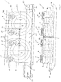
- FIG. 1 shows an oven according to the state of art.
- the oven 1 is divided into a first chamber 3 and a second chamber 4.
- the chambers are divided by means of a partition 2.
- a rotatable drum 5, 6 is arranged in each of these chambers, around which the conveyor belt 7 is guided along two helical paths 8, 9.
- the endless conveyor belt enters the oven 1 via the entrance 10 by a straight conveyor belt section 11 and leaves the oven 1 via the exit 12, likewise by means of a straight section 13.
- the two helical sections 8, 9 are connected by the straight conveyor belt section 14, which lies at the top.
- the partition means 2 comprise a passage 2.1 for the belt section 14. This passage 2.1 is larger than the conveyor belt 14. It has now been found, that a leakage 33 of the process-fluid e.g. air and steam occurs via this passage. This leakage-flow is unpredictable. Internal and external conditions can influence this leakage-flow in its magnitude and/or direction, so that the process-conditions in the oven are often not reproducible.
- the heating means which are overall denoted by 15, 19, 27, 28, are arranged in the top of the housing. These heating means 15, 19, 27, 28 each comprise a fan 16, 22 with a spiral casing 17, which opens into a duct 18, 23 - 25.
- the heating elements 34 are situated in the ducts, respectively.
- the process fluid e.g. air and steam, is sucked up by the fans out of chambers 3, 4 and is forced into the duct via the spiral casing 17, respectively.
- the process fluid 31, 32 flows past the heating elements 34 and is then reintroduced into the respective chamber 3, 4.
- the motion of the products (not depicted) to be cooked in the oven is depicted by arrows 29.
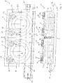
- Figure 2 shows the inventive oven, which comprises in the passage 2.1 guiding means 30 in the form of a tube or a tunnel.
- an airflow 26 is injected, which results in a higher pressure in the tube 30. This higher pressure forces the air 26 to flow to the left towards the first chamber 3 and to the right towards the second chamber 4.
- the magnitude of air flow 26 is preferably controllable such that the leakage is either reduced to zero or has a desired magnitude and a desired direction.
- the division of the flow 26 in the tube 30 is controlled.
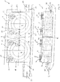
- FIG. 3 shows further details of the fluid injection into tube 30.
- Both branches 20.1, 20.2 of a Y-shaped duct 20 are connected to the ducts 23, 24, respectively.
- the ducts 23, 24 recycle the process fluid 31, 32 back into the chambers 3, 4, respectively.
- a valve 21 is arranged, which allows to control from which chamber 3, 4 the process fluid is taken. In the position of the valve as shown in figure 3 , all air is taken out of chamber 3. After the air flow 26 has passed the valve 21, it flow into the base 20.3 of the Y-shaped duct 20 and from there it is injected into tube 30, where it is split into the flows 26.1 and 26.2., which flow into chamber 3, 4, respectively.
- Valve 21 also allows to control the magnitude of flow 26.
- the setting of valve 21 can be done manually or automatically, for example by a PLC-controller.
- This PLC controller adjusts the valve 21, which is driven by a motor, based on desired process conditions and/or measured parameters like temperature and/or humidity in the individual chamber, especially based on the desired leakage in the passage.
- the inventive oven can comprise means, which is preferably located in the tube 30, to adjust the split of air flow 26.
- FIG. 4 shows valve 21 in detail.
- Figure 5 shows an example of controlled leakage between the first chamber 3 and the second chamber 4.
- the first chamber 3 is operated at a higher temperature and/or humidity than the second chamber 4.
- a controlled leakage 33 from the second to the first chamber is initiated, as depicted by arrow 33.
- This leakage is maintained until the process conditions in the first chamber are in the desired range and then stopped again.
- the place where the leakage 33 takes place can be the passage 2.1 but also any other fluid-connection between the two chambers.
- the controlled leakage between the two chambers can be initiated and maintained by reducing the pressure in the first chamber 3 and/or increasing the pressure in the second chamber 4.
- the reduction of the pressure in chamber 3 can be executed by removing air from this chamber for example through the inlet 10.
- air can be forced into chamber 4 to increase its pressure, for example via outlet 12.
- air from chamber 4 can be forced, for example by a fan, into chamber 3.
- Figure 6 shows another example of controlled leakage between the first chamber 3 and the second chamber 4.
- the first chamber 3 is operated at a higher temperature and/or humidity than the second chamber 4.
- a controlled leakage 33 from the first to the second chamber is initiated, as depicted by arrow 33.
- This leakage is maintained until the process conditions in the second chamber are in the desired range and then stopped.
- the place where the leakage 33 takes place can be the passage 2.1 but also any other fluid-connection between the two chambers.
- the controlled leakage between the two chambers can be initiated and maintained by increasing the pressure in the first chamber 3 and/or reducing the pressure in the second chamber 4.
- the reduction of the pressure in chamber 4 can be executed by removing air from this chamber for example through the outlet 12.
- air can be forced into chamber 3 to increase its pressure, for example via inlet 10.
- air from chamber 3 can be forced, for example by a fan, into chamber 4.
- Controlled leakages to the ambient are shown in Figure 7 and depicted by arrows 35.
- the controlled leakage to the ambient can be utilized to adjust a parameter in one or both of the chambers and/or to achieve a controlled leakage between the two chambers.
- the person skilled in the art understands that the leakage 35 need not take place at the inlet or the outlet.
- one chamber has an air exchange with the ambient, but no leakage between the chambers is desired, it can be suppressed by a fluid flow 26, as disclosed above.
- Figures 8 and 9 show another embodiment of controlled ventilation between the two chambers 3, 4 and/or the ambient 36.
- the pressure in chamber 4 is lower than the pressure in chamber 3.
- a fluid flow x is drawn out of chamber 4 and introduced into the guiding means 30 in the passage 2.1, where it is split into a fluid flow z which flows back to chamber 4 and a fluid flow y which flows in the direction of chamber 3.
- the pressure in the guiding means 30, where the fluid flow x is introduced, is higher than the pressure in chambers 3 and 4, respectively.
- the direction of the leakage is indicated with arrow 33.
- Figure 9 shows the oven according to figure 8 .
- the pressure in chamber 3 is lower than the pressure in chamber 4.
- the fluid flow x is taken out of chamber 3 introduced into the guiding means 30, where the pressure is higher than in chambers 3 and 4, respectively.
- the fluid flow x is split into a portion y, which flows back to chamber 3, and a portion z which flows to chamber 4.
- the leakage 33 is directed from chamber 3 to chamber 4 and amounts to fluid flow z.
- the same amount z has to be taken out of the ambient and introduced into chamber 3 and blown out of chamber 4 into the ambient 36.
- the process according to figure 9 is utilized to decrease the humidity and/or the temperature in chamber 3 and to increase the temperature and humidity in chamber 4, provided the temperature and humidity are higher in chamber 3 than in chamber 4, respectively.
Priority Applications (1)
| Application Number | Priority Date | Filing Date | Title |
|---|---|---|---|
| EP17189015.5A EP3335564B1 (fr) | 2008-04-18 | 2008-04-18 | Processus de contrôle du dèbit d'air et des fuites d'air entre deux chambres de cuisson |
Applications Claiming Priority (3)
| Application Number | Priority Date | Filing Date | Title |
|---|---|---|---|
| EP08007605.2A EP2110020B1 (fr) | 2008-04-18 | 2008-04-18 | Four et processus de contrôle du débit d'air et des fuites d'air entre deux chambres |
| EP13186178.3A EP2679097B1 (fr) | 2008-04-18 | 2008-04-18 | processus de contrôle du débit d'air et des fuites d'air entre deux chambres de cuisson |
| EP17189015.5A EP3335564B1 (fr) | 2008-04-18 | 2008-04-18 | Processus de contrôle du dèbit d'air et des fuites d'air entre deux chambres de cuisson |
Related Parent Applications (3)
| Application Number | Title | Priority Date | Filing Date |
|---|---|---|---|
| EP13186178.3A Division EP2679097B1 (fr) | 2008-04-18 | 2008-04-18 | processus de contrôle du débit d'air et des fuites d'air entre deux chambres de cuisson |
| EP13186178.3A Division-Into EP2679097B1 (fr) | 2008-04-18 | 2008-04-18 | processus de contrôle du débit d'air et des fuites d'air entre deux chambres de cuisson |
| EP08007605.2A Division EP2110020B1 (fr) | 2008-04-18 | 2008-04-18 | Four et processus de contrôle du débit d'air et des fuites d'air entre deux chambres |
Publications (2)
| Publication Number | Publication Date |
|---|---|
| EP3335564A1 true EP3335564A1 (fr) | 2018-06-20 |
| EP3335564B1 EP3335564B1 (fr) | 2020-09-23 |
Family
ID=39691309
Family Applications (3)
| Application Number | Title | Priority Date | Filing Date |
|---|---|---|---|
| EP08007605.2A Revoked EP2110020B1 (fr) | 2008-04-18 | 2008-04-18 | Four et processus de contrôle du débit d'air et des fuites d'air entre deux chambres |
| EP17189015.5A Active EP3335564B1 (fr) | 2008-04-18 | 2008-04-18 | Processus de contrôle du dèbit d'air et des fuites d'air entre deux chambres de cuisson |
| EP13186178.3A Active EP2679097B1 (fr) | 2008-04-18 | 2008-04-18 | processus de contrôle du débit d'air et des fuites d'air entre deux chambres de cuisson |
Family Applications Before (1)
| Application Number | Title | Priority Date | Filing Date |
|---|---|---|---|
| EP08007605.2A Revoked EP2110020B1 (fr) | 2008-04-18 | 2008-04-18 | Four et processus de contrôle du débit d'air et des fuites d'air entre deux chambres |
Family Applications After (1)
| Application Number | Title | Priority Date | Filing Date |
|---|---|---|---|
| EP13186178.3A Active EP2679097B1 (fr) | 2008-04-18 | 2008-04-18 | processus de contrôle du débit d'air et des fuites d'air entre deux chambres de cuisson |
Country Status (9)
| Country | Link |
|---|---|
| US (1) | US20110084056A1 (fr) |
| EP (3) | EP2110020B1 (fr) |
| JP (1) | JP2011516088A (fr) |
| KR (1) | KR20110013395A (fr) |
| BR (1) | BRPI0911102A2 (fr) |
| CA (1) | CA2721552A1 (fr) |
| ES (2) | ES2773122T3 (fr) |
| PL (2) | PL2110020T3 (fr) |
| WO (1) | WO2009127416A1 (fr) |
Cited By (1)
| Publication number | Priority date | Publication date | Assignee | Title |
|---|---|---|---|---|
| EP3335564B1 (fr) | 2008-04-18 | 2020-09-23 | GEA Food Solutions Bakel B.V. | Processus de contrôle du dèbit d'air et des fuites d'air entre deux chambres de cuisson |
Families Citing this family (9)
| Publication number | Priority date | Publication date | Assignee | Title |
|---|---|---|---|---|
| US8895096B2 (en) * | 2011-06-22 | 2014-11-25 | Frito-Lay North America, Inc. | Continuous oven with a cascading conveyor |
| US9161651B2 (en) * | 2012-01-27 | 2015-10-20 | Ts Techniek Bv | Dual drum spiral oven |
| US20150150269A1 (en) * | 2012-08-01 | 2015-06-04 | Frito-Lay North America, Inc. | Continuous process and apparatus for making a pita chip |
| WO2015134439A1 (fr) * | 2014-03-04 | 2015-09-11 | Cuisine Solutions, Inc. | Appareil et procédé pour traiter des côtés opposés d'un produit alimentaire solide |
| JP6909228B2 (ja) | 2015-11-17 | 2021-07-28 | ジーイーエイ・フード・ソリューションズ・バーケル・ベスローテン・フェンノートシャップ | 流体牽引が改良されたオーブン |
| US10463187B2 (en) | 2016-02-26 | 2019-11-05 | Provisur Technologies, Inc | Cooking devices and methods of using the same |
| NL2016385B1 (en) * | 2016-03-08 | 2017-09-27 | Marel Townsend Further Proc Bv | Closed processing system and method for treating elongated food products. |
| WO2017192955A1 (fr) | 2016-05-05 | 2017-11-09 | Provisur Technologies, Inc. | Dispositifs de cuisson en spirale et leurs procédés d'utilisation |
| US10912317B2 (en) | 2018-10-19 | 2021-02-09 | John Bean Technologies Ab | Thermal processing apparatus |
Citations (4)
| Publication number | Priority date | Publication date | Assignee | Title |
|---|---|---|---|---|
| EP0558151A1 (fr) | 1992-02-26 | 1993-09-01 | Tetra Laval Food Koppens B.V. | Four |
| EP1221575A1 (fr) | 2001-01-05 | 2002-07-10 | Koppens B.V. | Four avec système à jet de fluide |
| EP1249168A1 (fr) * | 2001-04-02 | 2002-10-16 | CFS Bakel B.V. | Four avec collection de gouttes |
| US20050092312A1 (en) * | 2003-10-31 | 2005-05-05 | Gunawardena Ramesh M. | Indirect and direct heated continuous oven system |
Family Cites Families (24)
| Publication number | Priority date | Publication date | Assignee | Title |
|---|---|---|---|---|
| US2256003A (en) | 1939-07-31 | 1941-09-16 | Curtis J Patterson | Apparatus for treating dough |
| GB621799A (en) | 1946-05-24 | 1949-04-20 | John Edward Pointon | Improvements in and relating to ovens for baking bread or the like |
| CH302518A (de) * | 1950-08-22 | 1954-10-31 | Spooner Food Machinery Enginee | Verfahren zur Herstellung von Backwaren und Vorrichtung zur Durchführung dieses Verfahrens. |
| DE2416189C2 (de) * | 1974-04-03 | 1982-12-09 | Rinderle, Karl, 8551 Gößweinstein | Verfahren zur Herstellung von Lebkuchen und Vorrichtung dafür |
| DE3225813A1 (de) * | 1982-07-09 | 1984-01-12 | Ing. Franz Prohaska GmbH, 8160 Weiz, Steiermark | Backofen |
| AU4435285A (en) * | 1984-05-31 | 1985-12-31 | Forney Robert Bruce | Continous feed oven |
| US4834063A (en) * | 1987-05-28 | 1989-05-30 | Stein Associates, Inc. | Food cooking oven with duct fingers and method |
| US4949629A (en) * | 1987-10-13 | 1990-08-21 | Heat And Control, Inc. | Cooking a food product in a process vapor at progressively varying rates |
| US4920998A (en) | 1988-03-21 | 1990-05-01 | Union Carbide Industrial Gases Technology Corporation | Method and apparatus for controlling flow bias in a multiple zone process |
| US6041398A (en) * | 1992-06-26 | 2000-03-21 | International Business Machines Corporation | Massively parallel multiple-folded clustered processor mesh array |
| US5243962A (en) * | 1990-01-26 | 1993-09-14 | Stein, Inc. | Cooking oven for slow-cooking of food products |
| US5078120A (en) | 1990-01-26 | 1992-01-07 | Stein, Inc. | Cooking oven for slow cooking of food products |
| US5335590A (en) | 1992-10-30 | 1994-08-09 | Philip Morris Incorporated | Apparatus for treatment of solid material |
| US5512312A (en) * | 1994-06-15 | 1996-04-30 | Forney; Robert B. | Radiant wall oven and method of using the same |
| US5673681A (en) * | 1996-01-17 | 1997-10-07 | Greenheck Fan Corporation | Ventilation system for conveyor oven |
| GB2315406B (en) * | 1996-07-23 | 2000-05-10 | Stein Inc | Cooking oven |
| IE990196A1 (en) * | 1998-03-12 | 1999-09-22 | Nicholas Jackman | A continuous cooking system |
| US6323462B1 (en) * | 2000-06-23 | 2001-11-27 | Wisconsin Oven Corporation | Conveyor oven usable as pre-bake oven in a print plate imaging and processing system and method of using same |
| AU2004273859A1 (en) * | 2003-09-16 | 2005-03-31 | Lincoln Foodservice Products, Inc. | Conveyor oven with improved air return and method |
| US8707861B2 (en) * | 2004-08-02 | 2014-04-29 | John Bean Technologies Corporation | Dry food pasteurization apparatus and method |
| NL1028252C2 (nl) * | 2005-02-11 | 2006-08-14 | Cfs Bakel Bv | Werkwijze voor het behandelen van voedselproducten, alsmede lijnoven daarvoor. |
| GB0518186D0 (en) * | 2005-09-07 | 2005-10-12 | Fylde Thermal Engineering Ltd | Tunnel oven |
| US7798059B2 (en) * | 2006-07-10 | 2010-09-21 | John Bean Technologies Corporation | Oven with improved stream chamber |
| EP2110020B1 (fr) | 2008-04-18 | 2014-07-09 | GEA Food Solutions Bakel B.V. | Four et processus de contrôle du débit d'air et des fuites d'air entre deux chambres |
-
2008
- 2008-04-18 EP EP08007605.2A patent/EP2110020B1/fr not_active Revoked
- 2008-04-18 EP EP17189015.5A patent/EP3335564B1/fr active Active
- 2008-04-18 ES ES13186178T patent/ES2773122T3/es active Active
- 2008-04-18 PL PL08007605T patent/PL2110020T3/pl unknown
- 2008-04-18 PL PL13186178T patent/PL2679097T3/pl unknown
- 2008-04-18 EP EP13186178.3A patent/EP2679097B1/fr active Active
- 2008-04-18 ES ES08007605.2T patent/ES2507506T3/es active Active
-
2009
- 2009-04-16 JP JP2011504376A patent/JP2011516088A/ja active Pending
- 2009-04-16 US US12/988,349 patent/US20110084056A1/en not_active Abandoned
- 2009-04-16 WO PCT/EP2009/002794 patent/WO2009127416A1/fr active Application Filing
- 2009-04-16 CA CA2721552A patent/CA2721552A1/fr not_active Abandoned
- 2009-04-16 BR BRPI0911102A patent/BRPI0911102A2/pt not_active IP Right Cessation
- 2009-04-16 KR KR1020107025426A patent/KR20110013395A/ko not_active Application Discontinuation
Patent Citations (4)
| Publication number | Priority date | Publication date | Assignee | Title |
|---|---|---|---|---|
| EP0558151A1 (fr) | 1992-02-26 | 1993-09-01 | Tetra Laval Food Koppens B.V. | Four |
| EP1221575A1 (fr) | 2001-01-05 | 2002-07-10 | Koppens B.V. | Four avec système à jet de fluide |
| EP1249168A1 (fr) * | 2001-04-02 | 2002-10-16 | CFS Bakel B.V. | Four avec collection de gouttes |
| US20050092312A1 (en) * | 2003-10-31 | 2005-05-05 | Gunawardena Ramesh M. | Indirect and direct heated continuous oven system |
Cited By (1)
| Publication number | Priority date | Publication date | Assignee | Title |
|---|---|---|---|---|
| EP3335564B1 (fr) | 2008-04-18 | 2020-09-23 | GEA Food Solutions Bakel B.V. | Processus de contrôle du dèbit d'air et des fuites d'air entre deux chambres de cuisson |
Also Published As
| Publication number | Publication date |
|---|---|
| ES2507506T3 (es) | 2014-10-15 |
| EP3335564B1 (fr) | 2020-09-23 |
| EP2679097B1 (fr) | 2019-11-13 |
| EP2110020B1 (fr) | 2014-07-09 |
| JP2011516088A (ja) | 2011-05-26 |
| US20110084056A1 (en) | 2011-04-14 |
| PL2110020T3 (pl) | 2015-01-30 |
| EP2679097A1 (fr) | 2014-01-01 |
| BRPI0911102A2 (pt) | 2015-10-06 |
| EP2110020A1 (fr) | 2009-10-21 |
| ES2773122T3 (es) | 2020-07-09 |
| PL2679097T3 (pl) | 2020-06-01 |
| CA2721552A1 (fr) | 2009-10-22 |
| KR20110013395A (ko) | 2011-02-09 |
| WO2009127416A1 (fr) | 2009-10-22 |
Similar Documents
| Publication | Publication Date | Title |
|---|---|---|
| EP3335564B1 (fr) | Processus de contrôle du dèbit d'air et des fuites d'air entre deux chambres de cuisson | |
| EP2135509B1 (fr) | Four avec une contrôle du débit d'air sur la largeur d'une courroie dans un four à spirale | |
| EP2234499B1 (fr) | Ensemble de traitement de produits alimentaires comprenant deux dispositifs de traitement | |
| EP3365606B1 (fr) | Four à convection | |
| US9700059B2 (en) | Treatment device and method for treating food products with conditioned air | |
| US9375016B2 (en) | Convection heating in track ovens | |
| CN1596666A (zh) | 对流型烤炉及其空气流动系统 | |
| EP2162006B1 (fr) | Four tunnel à gaz | |
| US6909069B2 (en) | Baking oven | |
| EP3376872B1 (fr) | Four à traînée améliorée | |
| EP3431884B1 (fr) | Four de cuisson pour aliments | |
| SU839460A1 (ru) | Хлебопекарна печь |
Legal Events
| Date | Code | Title | Description |
|---|---|---|---|
| PUAI | Public reference made under article 153(3) epc to a published international application that has entered the european phase |
Free format text: ORIGINAL CODE: 0009012 |
|
| STAA | Information on the status of an ep patent application or granted ep patent |
Free format text: STATUS: THE APPLICATION HAS BEEN PUBLISHED |
|
| AC | Divisional application: reference to earlier application |
Ref document number: 2679097 Country of ref document: EP Kind code of ref document: P Ref document number: 2110020 Country of ref document: EP Kind code of ref document: P |
|
| AK | Designated contracting states |
Kind code of ref document: A1 Designated state(s): AT BE BG CH CY CZ DE DK EE ES FI FR GB GR HR HU IE IS IT LI LT LU LV MC MT NL NO PL PT RO SE SI SK TR |
|
| STAA | Information on the status of an ep patent application or granted ep patent |
Free format text: STATUS: REQUEST FOR EXAMINATION WAS MADE |
|
| 17P | Request for examination filed |
Effective date: 20181219 |
|
| RBV | Designated contracting states (corrected) |
Designated state(s): AT BE BG CH CY CZ DE DK EE ES FI FR GB GR HR HU IE IS IT LI LT LU LV MC MT NL NO PL PT RO SE SI SK TR |
|
| STAA | Information on the status of an ep patent application or granted ep patent |
Free format text: STATUS: EXAMINATION IS IN PROGRESS |
|
| 17Q | First examination report despatched |
Effective date: 20190801 |
|
| GRAP | Despatch of communication of intention to grant a patent |
Free format text: ORIGINAL CODE: EPIDOSNIGR1 |
|
| STAA | Information on the status of an ep patent application or granted ep patent |
Free format text: STATUS: GRANT OF PATENT IS INTENDED |
|
| INTG | Intention to grant announced |
Effective date: 20200331 |
|
| GRAS | Grant fee paid |
Free format text: ORIGINAL CODE: EPIDOSNIGR3 |
|
| GRAA | (expected) grant |
Free format text: ORIGINAL CODE: 0009210 |
|
| STAA | Information on the status of an ep patent application or granted ep patent |
Free format text: STATUS: THE PATENT HAS BEEN GRANTED |
|
| RAP1 | Party data changed (applicant data changed or rights of an application transferred) |
Owner name: GEA FOOD SOLUTIONS BAKEL B.V. |
|
| AC | Divisional application: reference to earlier application |
Ref document number: 2110020 Country of ref document: EP Kind code of ref document: P Ref document number: 2679097 Country of ref document: EP Kind code of ref document: P |
|
| AK | Designated contracting states |
Kind code of ref document: B1 Designated state(s): AT BE BG CH CY CZ DE DK EE ES FI FR GB GR HR HU IE IS IT LI LT LU LV MC MT NL NO PL PT RO SE SI SK TR |
|
| REG | Reference to a national code |
Ref country code: GB Ref legal event code: FG4D |
|
| REG | Reference to a national code |
Ref country code: CH Ref legal event code: EP |
|
| REG | Reference to a national code |
Ref country code: IE Ref legal event code: FG4D |
|
| REG | Reference to a national code |
Ref country code: DE Ref legal event code: R096 Ref document number: 602008063307 Country of ref document: DE Ref country code: AT Ref legal event code: REF Ref document number: 1315447 Country of ref document: AT Kind code of ref document: T Effective date: 20201015 |
|
| REG | Reference to a national code |
Ref country code: SK Ref legal event code: T3 Ref document number: E 35898 Country of ref document: SK |
|
| PG25 | Lapsed in a contracting state [announced via postgrant information from national office to epo] |
Ref country code: HR Free format text: LAPSE BECAUSE OF FAILURE TO SUBMIT A TRANSLATION OF THE DESCRIPTION OR TO PAY THE FEE WITHIN THE PRESCRIBED TIME-LIMIT Effective date: 20200923 Ref country code: BG Free format text: LAPSE BECAUSE OF FAILURE TO SUBMIT A TRANSLATION OF THE DESCRIPTION OR TO PAY THE FEE WITHIN THE PRESCRIBED TIME-LIMIT Effective date: 20201223 Ref country code: NO Free format text: LAPSE BECAUSE OF FAILURE TO SUBMIT A TRANSLATION OF THE DESCRIPTION OR TO PAY THE FEE WITHIN THE PRESCRIBED TIME-LIMIT Effective date: 20201223 Ref country code: GR Free format text: LAPSE BECAUSE OF FAILURE TO SUBMIT A TRANSLATION OF THE DESCRIPTION OR TO PAY THE FEE WITHIN THE PRESCRIBED TIME-LIMIT Effective date: 20201224 Ref country code: FI Free format text: LAPSE BECAUSE OF FAILURE TO SUBMIT A TRANSLATION OF THE DESCRIPTION OR TO PAY THE FEE WITHIN THE PRESCRIBED TIME-LIMIT Effective date: 20200923 Ref country code: SE Free format text: LAPSE BECAUSE OF FAILURE TO SUBMIT A TRANSLATION OF THE DESCRIPTION OR TO PAY THE FEE WITHIN THE PRESCRIBED TIME-LIMIT Effective date: 20200923 |
|
| REG | Reference to a national code |
Ref country code: AT Ref legal event code: MK05 Ref document number: 1315447 Country of ref document: AT Kind code of ref document: T Effective date: 20200923 |
|
| PG25 | Lapsed in a contracting state [announced via postgrant information from national office to epo] |
Ref country code: LV Free format text: LAPSE BECAUSE OF FAILURE TO SUBMIT A TRANSLATION OF THE DESCRIPTION OR TO PAY THE FEE WITHIN THE PRESCRIBED TIME-LIMIT Effective date: 20200923 |
|
| REG | Reference to a national code |
Ref country code: LT Ref legal event code: MG4D |
|
| PG25 | Lapsed in a contracting state [announced via postgrant information from national office to epo] |
Ref country code: LT Free format text: LAPSE BECAUSE OF FAILURE TO SUBMIT A TRANSLATION OF THE DESCRIPTION OR TO PAY THE FEE WITHIN THE PRESCRIBED TIME-LIMIT Effective date: 20200923 Ref country code: PT Free format text: LAPSE BECAUSE OF FAILURE TO SUBMIT A TRANSLATION OF THE DESCRIPTION OR TO PAY THE FEE WITHIN THE PRESCRIBED TIME-LIMIT Effective date: 20210125 Ref country code: RO Free format text: LAPSE BECAUSE OF FAILURE TO SUBMIT A TRANSLATION OF THE DESCRIPTION OR TO PAY THE FEE WITHIN THE PRESCRIBED TIME-LIMIT Effective date: 20200923 Ref country code: CZ Free format text: LAPSE BECAUSE OF FAILURE TO SUBMIT A TRANSLATION OF THE DESCRIPTION OR TO PAY THE FEE WITHIN THE PRESCRIBED TIME-LIMIT Effective date: 20200923 Ref country code: EE Free format text: LAPSE BECAUSE OF FAILURE TO SUBMIT A TRANSLATION OF THE DESCRIPTION OR TO PAY THE FEE WITHIN THE PRESCRIBED TIME-LIMIT Effective date: 20200923 |
|
| PG25 | Lapsed in a contracting state [announced via postgrant information from national office to epo] |
Ref country code: ES Free format text: LAPSE BECAUSE OF FAILURE TO SUBMIT A TRANSLATION OF THE DESCRIPTION OR TO PAY THE FEE WITHIN THE PRESCRIBED TIME-LIMIT Effective date: 20200923 Ref country code: AT Free format text: LAPSE BECAUSE OF FAILURE TO SUBMIT A TRANSLATION OF THE DESCRIPTION OR TO PAY THE FEE WITHIN THE PRESCRIBED TIME-LIMIT Effective date: 20200923 Ref country code: IS Free format text: LAPSE BECAUSE OF FAILURE TO SUBMIT A TRANSLATION OF THE DESCRIPTION OR TO PAY THE FEE WITHIN THE PRESCRIBED TIME-LIMIT Effective date: 20210123 Ref country code: PL Free format text: LAPSE BECAUSE OF FAILURE TO SUBMIT A TRANSLATION OF THE DESCRIPTION OR TO PAY THE FEE WITHIN THE PRESCRIBED TIME-LIMIT Effective date: 20200923 |
|
| REG | Reference to a national code |
Ref country code: DE Ref legal event code: R026 Ref document number: 602008063307 Country of ref document: DE |
|
| PLBI | Opposition filed |
Free format text: ORIGINAL CODE: 0009260 |
|
| PLAX | Notice of opposition and request to file observation + time limit sent |
Free format text: ORIGINAL CODE: EPIDOSNOBS2 |
|
| 26 | Opposition filed |
Opponent name: MAREL FURTHER PROCESSING B.V. Effective date: 20210621 |
|
| PG25 | Lapsed in a contracting state [announced via postgrant information from national office to epo] |
Ref country code: DK Free format text: LAPSE BECAUSE OF FAILURE TO SUBMIT A TRANSLATION OF THE DESCRIPTION OR TO PAY THE FEE WITHIN THE PRESCRIBED TIME-LIMIT Effective date: 20200923 Ref country code: SI Free format text: LAPSE BECAUSE OF FAILURE TO SUBMIT A TRANSLATION OF THE DESCRIPTION OR TO PAY THE FEE WITHIN THE PRESCRIBED TIME-LIMIT Effective date: 20200923 |
|
| REG | Reference to a national code |
Ref country code: NL Ref legal event code: FP |
|
| PG25 | Lapsed in a contracting state [announced via postgrant information from national office to epo] |
Ref country code: IT Free format text: LAPSE BECAUSE OF FAILURE TO SUBMIT A TRANSLATION OF THE DESCRIPTION OR TO PAY THE FEE WITHIN THE PRESCRIBED TIME-LIMIT Effective date: 20200923 |
|
| REG | Reference to a national code |
Ref country code: DE Ref legal event code: R119 Ref document number: 602008063307 Country of ref document: DE |
|
| PLAZ | Examination of admissibility of opposition: despatch of communication + time limit |
Free format text: ORIGINAL CODE: EPIDOSNOPE2 |
|
| PLBB | Reply of patent proprietor to notice(s) of opposition received |
Free format text: ORIGINAL CODE: EPIDOSNOBS3 |
|
| PG25 | Lapsed in a contracting state [announced via postgrant information from national office to epo] |
Ref country code: MC Free format text: LAPSE BECAUSE OF FAILURE TO SUBMIT A TRANSLATION OF THE DESCRIPTION OR TO PAY THE FEE WITHIN THE PRESCRIBED TIME-LIMIT Effective date: 20200923 |
|
| PLBA | Examination of admissibility of opposition: reply received |
Free format text: ORIGINAL CODE: EPIDOSNOPE4 |
|
| PG25 | Lapsed in a contracting state [announced via postgrant information from national office to epo] |
Ref country code: LU Free format text: LAPSE BECAUSE OF NON-PAYMENT OF DUE FEES Effective date: 20210418 |
|
| REG | Reference to a national code |
Ref country code: BE Ref legal event code: MM Effective date: 20210430 |
|
| PG25 | Lapsed in a contracting state [announced via postgrant information from national office to epo] |
Ref country code: LI Free format text: LAPSE BECAUSE OF NON-PAYMENT OF DUE FEES Effective date: 20210430 Ref country code: CH Free format text: LAPSE BECAUSE OF NON-PAYMENT OF DUE FEES Effective date: 20210430 Ref country code: DE Free format text: LAPSE BECAUSE OF NON-PAYMENT OF DUE FEES Effective date: 20211103 Ref country code: FR Free format text: LAPSE BECAUSE OF NON-PAYMENT OF DUE FEES Effective date: 20210430 |
|
| PG25 | Lapsed in a contracting state [announced via postgrant information from national office to epo] |
Ref country code: IE Free format text: LAPSE BECAUSE OF NON-PAYMENT OF DUE FEES Effective date: 20210418 |
|
| PG25 | Lapsed in a contracting state [announced via postgrant information from national office to epo] |
Ref country code: IS Free format text: LAPSE BECAUSE OF FAILURE TO SUBMIT A TRANSLATION OF THE DESCRIPTION OR TO PAY THE FEE WITHIN THE PRESCRIBED TIME-LIMIT Effective date: 20210123 |
|
| PG25 | Lapsed in a contracting state [announced via postgrant information from national office to epo] |
Ref country code: BE Free format text: LAPSE BECAUSE OF NON-PAYMENT OF DUE FEES Effective date: 20210430 |
|
| APAH | Appeal reference modified |
Free format text: ORIGINAL CODE: EPIDOSCREFNO |
|
| APBM | Appeal reference recorded |
Free format text: ORIGINAL CODE: EPIDOSNREFNO |
|
| APBP | Date of receipt of notice of appeal recorded |
Free format text: ORIGINAL CODE: EPIDOSNNOA2O |
|
| APBQ | Date of receipt of statement of grounds of appeal recorded |
Free format text: ORIGINAL CODE: EPIDOSNNOA3O |
|
| PG25 | Lapsed in a contracting state [announced via postgrant information from national office to epo] |
Ref country code: CY Free format text: LAPSE BECAUSE OF FAILURE TO SUBMIT A TRANSLATION OF THE DESCRIPTION OR TO PAY THE FEE WITHIN THE PRESCRIBED TIME-LIMIT Effective date: 20200923 |
|
| P01 | Opt-out of the competence of the unified patent court (upc) registered |
Effective date: 20230517 |
|
| PGFP | Annual fee paid to national office [announced via postgrant information from national office to epo] |
Ref country code: NL Payment date: 20230417 Year of fee payment: 16 |
|
| PG25 | Lapsed in a contracting state [announced via postgrant information from national office to epo] |
Ref country code: HU Free format text: LAPSE BECAUSE OF FAILURE TO SUBMIT A TRANSLATION OF THE DESCRIPTION OR TO PAY THE FEE WITHIN THE PRESCRIBED TIME-LIMIT; INVALID AB INITIO Effective date: 20080418 |
|
| PGFP | Annual fee paid to national office [announced via postgrant information from national office to epo] |
Ref country code: SK Payment date: 20230412 Year of fee payment: 16 |
|
| PGFP | Annual fee paid to national office [announced via postgrant information from national office to epo] |
Ref country code: GB Payment date: 20230420 Year of fee payment: 16 |