EP3335420B1 - Systems and methods for multiscopic noise reduction and high-dynamic range - Google Patents
Systems and methods for multiscopic noise reduction and high-dynamic range Download PDFInfo
- Publication number
- EP3335420B1 EP3335420B1 EP16873617.1A EP16873617A EP3335420B1 EP 3335420 B1 EP3335420 B1 EP 3335420B1 EP 16873617 A EP16873617 A EP 16873617A EP 3335420 B1 EP3335420 B1 EP 3335420B1
- Authority
- EP
- European Patent Office
- Prior art keywords
- image
- image data
- image capture
- capture system
- burst
- Prior art date
- Legal status (The legal status is an assumption and is not a legal conclusion. Google has not performed a legal analysis and makes no representation as to the accuracy of the status listed.)
- Active
Links
Images


Classifications
-
- H—ELECTRICITY
- H04—ELECTRIC COMMUNICATION TECHNIQUE
- H04N—PICTORIAL COMMUNICATION, e.g. TELEVISION
- H04N13/00—Stereoscopic video systems; Multi-view video systems; Details thereof
- H04N13/20—Image signal generators
- H04N13/204—Image signal generators using stereoscopic image cameras
- H04N13/239—Image signal generators using stereoscopic image cameras using two two-dimensional [2D] image sensors having a relative position equal to or related to the interocular distance
-
- G—PHYSICS
- G06—COMPUTING OR CALCULATING; COUNTING
- G06T—IMAGE DATA PROCESSING OR GENERATION, IN GENERAL
- G06T5/00—Image enhancement or restoration
- G06T5/10—Image enhancement or restoration using non-spatial domain filtering
-
- G—PHYSICS
- G06—COMPUTING OR CALCULATING; COUNTING
- G06T—IMAGE DATA PROCESSING OR GENERATION, IN GENERAL
- G06T5/00—Image enhancement or restoration
- G06T5/70—Denoising; Smoothing
-
- G—PHYSICS
- G06—COMPUTING OR CALCULATING; COUNTING
- G06T—IMAGE DATA PROCESSING OR GENERATION, IN GENERAL
- G06T5/00—Image enhancement or restoration
- G06T5/90—Dynamic range modification of images or parts thereof
-
- G—PHYSICS
- G06—COMPUTING OR CALCULATING; COUNTING
- G06T—IMAGE DATA PROCESSING OR GENERATION, IN GENERAL
- G06T7/00—Image analysis
- G06T7/20—Analysis of motion
- G06T7/269—Analysis of motion using gradient-based methods
-
- G—PHYSICS
- G06—COMPUTING OR CALCULATING; COUNTING
- G06T—IMAGE DATA PROCESSING OR GENERATION, IN GENERAL
- G06T7/00—Image analysis
- G06T7/20—Analysis of motion
- G06T7/292—Multi-camera tracking
-
- G—PHYSICS
- G06—COMPUTING OR CALCULATING; COUNTING
- G06T—IMAGE DATA PROCESSING OR GENERATION, IN GENERAL
- G06T7/00—Image analysis
- G06T7/30—Determination of transform parameters for the alignment of images, i.e. image registration
-
- G—PHYSICS
- G06—COMPUTING OR CALCULATING; COUNTING
- G06T—IMAGE DATA PROCESSING OR GENERATION, IN GENERAL
- G06T7/00—Image analysis
- G06T7/30—Determination of transform parameters for the alignment of images, i.e. image registration
- G06T7/38—Registration of image sequences
-
- H—ELECTRICITY
- H04—ELECTRIC COMMUNICATION TECHNIQUE
- H04N—PICTORIAL COMMUNICATION, e.g. TELEVISION
- H04N13/00—Stereoscopic video systems; Multi-view video systems; Details thereof
- H04N13/20—Image signal generators
- H04N13/204—Image signal generators using stereoscopic image cameras
- H04N13/25—Image signal generators using stereoscopic image cameras using two or more image sensors with different characteristics other than in their location or field of view, e.g. having different resolutions or colour pickup characteristics; using image signals from one sensor to control the characteristics of another sensor
-
- H—ELECTRICITY
- H04—ELECTRIC COMMUNICATION TECHNIQUE
- H04N—PICTORIAL COMMUNICATION, e.g. TELEVISION
- H04N13/00—Stereoscopic video systems; Multi-view video systems; Details thereof
- H04N13/20—Image signal generators
- H04N13/271—Image signal generators wherein the generated image signals comprise depth maps or disparity maps
-
- H—ELECTRICITY
- H04—ELECTRIC COMMUNICATION TECHNIQUE
- H04N—PICTORIAL COMMUNICATION, e.g. TELEVISION
- H04N23/00—Cameras or camera modules comprising electronic image sensors; Control thereof
- H04N23/10—Cameras or camera modules comprising electronic image sensors; Control thereof for generating image signals from different wavelengths
- H04N23/13—Cameras or camera modules comprising electronic image sensors; Control thereof for generating image signals from different wavelengths with multiple sensors
-
- H—ELECTRICITY
- H04—ELECTRIC COMMUNICATION TECHNIQUE
- H04N—PICTORIAL COMMUNICATION, e.g. TELEVISION
- H04N23/00—Cameras or camera modules comprising electronic image sensors; Control thereof
- H04N23/60—Control of cameras or camera modules
- H04N23/68—Control of cameras or camera modules for stable pick-up of the scene, e.g. compensating for camera body vibrations
- H04N23/682—Vibration or motion blur correction
- H04N23/683—Vibration or motion blur correction performed by a processor, e.g. controlling the readout of an image memory
-
- H—ELECTRICITY
- H04—ELECTRIC COMMUNICATION TECHNIQUE
- H04N—PICTORIAL COMMUNICATION, e.g. TELEVISION
- H04N23/00—Cameras or camera modules comprising electronic image sensors; Control thereof
- H04N23/70—Circuitry for compensating brightness variation in the scene
- H04N23/741—Circuitry for compensating brightness variation in the scene by increasing the dynamic range of the image compared to the dynamic range of the electronic image sensors
-
- H—ELECTRICITY
- H04—ELECTRIC COMMUNICATION TECHNIQUE
- H04N—PICTORIAL COMMUNICATION, e.g. TELEVISION
- H04N23/00—Cameras or camera modules comprising electronic image sensors; Control thereof
- H04N23/80—Camera processing pipelines; Components thereof
- H04N23/84—Camera processing pipelines; Components thereof for processing colour signals
-
- H—ELECTRICITY
- H04—ELECTRIC COMMUNICATION TECHNIQUE
- H04N—PICTORIAL COMMUNICATION, e.g. TELEVISION
- H04N25/00—Circuitry of solid-state image sensors [SSIS]; Control thereof
- H04N25/60—Noise processing, e.g. detecting, correcting, reducing or removing noise
-
- H—ELECTRICITY
- H04—ELECTRIC COMMUNICATION TECHNIQUE
- H04N—PICTORIAL COMMUNICATION, e.g. TELEVISION
- H04N9/00—Details of colour television systems
- H04N9/64—Circuits for processing colour signals
-
- G—PHYSICS
- G06—COMPUTING OR CALCULATING; COUNTING
- G06T—IMAGE DATA PROCESSING OR GENERATION, IN GENERAL
- G06T2207/00—Indexing scheme for image analysis or image enhancement
- G06T2207/10—Image acquisition modality
- G06T2207/10004—Still image; Photographic image
- G06T2207/10012—Stereo images
-
- G—PHYSICS
- G06—COMPUTING OR CALCULATING; COUNTING
- G06T—IMAGE DATA PROCESSING OR GENERATION, IN GENERAL
- G06T2207/00—Indexing scheme for image analysis or image enhancement
- G06T2207/10—Image acquisition modality
- G06T2207/10024—Color image
-
- G—PHYSICS
- G06—COMPUTING OR CALCULATING; COUNTING
- G06T—IMAGE DATA PROCESSING OR GENERATION, IN GENERAL
- G06T2207/00—Indexing scheme for image analysis or image enhancement
- G06T2207/20—Special algorithmic details
- G06T2207/20172—Image enhancement details
- G06T2207/20208—High dynamic range [HDR] image processing
-
- H—ELECTRICITY
- H04—ELECTRIC COMMUNICATION TECHNIQUE
- H04N—PICTORIAL COMMUNICATION, e.g. TELEVISION
- H04N13/00—Stereoscopic video systems; Multi-view video systems; Details thereof
- H04N2013/0074—Stereoscopic image analysis
- H04N2013/0081—Depth or disparity estimation from stereoscopic image signals
-
- H—ELECTRICITY
- H04—ELECTRIC COMMUNICATION TECHNIQUE
- H04N—PICTORIAL COMMUNICATION, e.g. TELEVISION
- H04N13/00—Stereoscopic video systems; Multi-view video systems; Details thereof
- H04N2013/0074—Stereoscopic image analysis
- H04N2013/0088—Synthesising a monoscopic image signal from stereoscopic images, e.g. synthesising a panoramic or high resolution monoscopic image
Definitions
- Multiscopic imaging systems are operable to capture multiple images of a scene.
- the captured images may include common elements from the scene as imaged from different viewing points, from different viewing angles, and/or over different periods of time.
- image correction may be applied to at least one of the multiple images based on the common elements from the captured images.
- United States Patent Application Publication No. US 2013/0064470 A1 discloses that when noise of an image is reduced by using a plurality of sheets of images, a noise of a portion which cannot be aligned cannot be reduced. Aligning processing of the plural images is performed to generate an average image formed by pixels subjected to the aligning processing. Further, a difference between average image data representing the average image and input image data representing an input image is calculated, and the noise of the input image is reduced by using the calculated difference.
- Embodiments in the present disclosure relate to methods and systems for improving image quality in stereoscopic, and more generally, multiscopic imaging systems.
- Image pairs from a stereoscopic imaging system are spatially aligned and warped to correct for image parallax.
- the aligned and warped image pairs are "stacked".
- Noise reduction algorithms may be applied to the stacked images.
- High dynamic range algorithms may be applied to one or more denoised images.
- a combination of fast, high resolution estimation of stereo disparity, with a robust burst denoising and HDR processing applied to a simultaneously captured image pair, or image bursts, may provide high resolution, low noise images in less time than is possible using a burst from a single camera.
- a method includes, receiving, by a computing system, burst image data, wherein the burst image data comprises first image data generated by a first image-capture system and second image data generated by a second image-capture system, wherein respective optical axes of the first and second image capture systems are separated by a baseline distance, wherein the first image data and the second image data comprise a plurality of image pairs, wherein an image pair comprises a first image generated by the first image capture system and a second image generated by the second image capture system, the first and second images captured substantially simultaneously.
- the method further includes determining, by the computing system, at least one rectifying homography function, wherein the at least one rectifying homography function is configured to transform the first image and/or the second image of each respective image pair of the plurality of the image pairs to emulate having a common image plane between the first and second images of each respective image pair; and applying the at least one homography function to at least one of the first image data or the second image data.
- the method further includes determining, by the computing system, a disparity of the burst image data based at least on the baseline distance and adjusting at least one of the first image data or the second image data according to an inverse of the determined stereo disparity such that the first and second images of each respective image pair are spatially aligned and substantially match; and stacking the adjusted image data to provide a warped image stack of substantially similar images for the application of a burst denoising algorithm.
- the method further includes generating at least one output image according to a burst denoising algorithm, wherein the burst denoising algorithm comprises determining a weighted average of the warped image stack.
- the respective optical axes of the first and second image capture systems are oriented in substantially the same direction.
- a system comprising a plurality of image capture systems, wherein the plurality of image capture systems comprises at least a first image capture system and a second image capture system, wherein the first image capture system is operable to capture first image data and the second image capture system is operable to capture second image data, wherein respective optical axes of the first and second image capture systems are separated by a baseline distance, wherein the first image data and the second image data comprise burst image data having a plurality of image pairs, wherein an image pair comprises a first image generated by the first image capture system and a second image generated by the second image capture system, the first and second images captured substantially simultaneously.
- the system further comprises a controller comprising a memory and a processor, wherein the memory is configured to contain instructions, and wherein processor is configured to execute the instructions to carry out a method according to the above aspect providing a method.
- the at least one rectifying homography function may comprise a function for correcting geometric distortion and a photometric pixel correction function.
- the weighted average may comprise a per-pixel average of corresponding pixels of the warped image stack.
- the method may further comprise applying a high dynamic range (HDR) function to the at least one output image to provide at least one HDR output image.
- the first image capture system may comprise an image sensor optically coupled to a color filter array, and the second image capture system may comprise an image sensor without a color filter array.
- the burst image data may comprise images formatted according to at least one of: a raw image format, a WebP image format, or a JPEG image format.
- the burst image data may comprise between 2 and 100 images.
- the first image capture system may comprise an image sensor optically coupled to a low pass filter
- the second image capture system may comprise an image sensor without a low pass filter.
- the first image capture system may comprise an image sensor optically coupled to optics having a first focal length
- the second image capture system may comprise an image sensor optically coupled to optics having a second focal length, wherein the first focal length and the second focal length are different.
- the plurality of image capture systems may be arranged along a boundary of a shape, wherein the shape comprises one of: a ring, a disk, or a sphere.
- the computing system may comprise a controller comprising at least one programmable in-circuit serial programming (ICSP) microcontroller.
- ICSP programmable in-circuit serial programming
- a computer-readable medium comprises processor-executable instructions that when executed causes a computer to carry out operations according to any of the aspects described herein.
- the above aspects seek to address problems associated with noise reduction in image capture systems.
- the present disclosure relates to methods and systems that provide noise reduction and high-dynamic range in stereo- and multi-scopic camera systems.
- Digital photography quality particularly for consumer devices such as cellphone cameras, may be limited by small sensor and aperture size. Such characteristics may limit the number of photons that can be captured, which may proportionately increase "shot noise" or the random variance in the number of photons absorbed by a sensor pixel. Increasing the shutter length reduces this noise, but at the possible cost of increased motion blur.
- burst photography in which instead of taking a single photograph, a camera rapidly takes N photographs. These N images are then merged using one of a variety of algorithms, which results in lower noise and greater dynamic range per-pixel.
- the problem is that a burst of N photos takes N times as long as a single photo, which may negatively impact the user experience, and also increases the amount of scene motion during the capture.
- burst photography may be performed by a stereoscopic or multiscopic camera system.
- the burst image data is rectified, warped, and denoised to provide a higher quality output image.
- high resolution, low noise images may be generated in half the time (or less) of a single image sensor burst.
- a stereoscopic camera system captures burst image data.
- the image "burst" may include 1-10 images captured by each image sensor of the camera in rapid succession. That is, the burst image data includes first image data (e.g., from a first image sensor) and second image data (e.g., from a second image sensor) that include a plurality of image pairs. The image pairs include corresponding images from the first and second image data captured substantially simultaneously in sequence by the first and second image sensors.
- the burst image data may include images formatted according to a RAW image format, a WebP image format, a JPEG image format, or another type of image format. Furthermore, in some embodiments, the burst image data may include between 2 and 100 images.
- At least one rectifying homography function is determined by a controller of the system.
- the rectifying homography function(s) is determined so as to adjust one or both images of the image pair such that the two images of the image pair are spatially aligned.
- the rectifying homography function(s) may be determined based on a camera "factory" calibration. Additionally or alternatively, the rectifying homography function(s) may be determined based on another type of calibration.
- the rectifying homography function(s) may include a geometric pixel correction function and a photometric pixel correction function.
- the alignment techniques disclosed herein may include linear transformations (e.g., rotation, scaling, translation, etc.) and/or non-rigid transformations (e.g., local warping of an image to align with a reference image).
- non-rigid transformations may include "optical flow" transforms.
- the controller is configured to determine a stereo disparity of the burst image data based on at least the baseline distance.
- the stereo disparity may be determined as part of a three-dimensional image processing method.
- the determination of the stereo disparity may include estimating a parallax function based on the first image data, the second image data, and the baseline distance.
- the controller warps at least one image of each image pair according to the determined stereo disparity. That is, the controller adjusts the at least one image of each image pair such that it substantially matches the corresponding image of the image pair.
- the controller may select a base image from the image pair or from the burst image data more generally. In such a scenario, the controller may adjust all of, or at least a portion of, the other images in the burst image data to substantially match the base image. That is, each other image of the burst image data may be adjusted to match the base image.
- each other image of the burst image data may be: 1) captured with a different image capture system at the same point in time; 2) captured with the same image capture system at a different point in time; or 3) captured with a different image capture system at a different point in time.
- Such image adjustments includes applying an inverse of the estimated parallax function to at least one of the first image data or the second image data.
- the image adjustments may include warping one or more images of the burst image data based on information about the epipolar geometry of the image capture systems. Such adjustments and/or warping of the burst image data forms a warped image stack.
- the controller may generate at least one output image based on a weighted, per-pixel average of the warped image stack.
- the controller may group pixels from the warped image stack together in respective image tiles.
- the controller may generate the at least one output image based on a weighted average of the respective image tiles.
- the respective image tiles may or may not overlap with other image tiles. Other denoising techniques based on a plurality of similar images are contemplated herein.
- the controller may further apply a high dynamic range (HDR) function to the at least one output image to provide at least one HDR output image.
- HDR high dynamic range
- the imaging system may include a first image capture system having an image sensor optically coupled to a color filter array (e.g., a Bayer filter) and a second image capture system having an image sensor without such a color filter array.
- a first image capture system may include an image sensor optically coupled to a low pass filter and a second image capture system may include an image sensor without such a low pass filter.
- systems contemplated herein may include image capture systems with optics that have different focal lengths. That is, first image data may be captured with a first focal length and second image data may be captured with a second focal length, providing different "zoom" levels of a given scene.
- the plurality of image capture systems may be arranged in various ways.
- the image capture systems may be arranged along a line, such as with most stereoscopic imaging systems.
- the image capture systems may be arranged along a boundary of a shape.
- the shape may include a ring or a sphere.
- the image capture systems may be operable to capture a 360 degree field of view.
- Other types of multiscopic image capture systems are contemplated.
- the controller described herein may include at least one programmable in-circuit serial programming (ICSP) microcontroller. Additionally or alternatively, other types of microprocessors, such as a graphical processing unit (GPU), are contemplated herein.
- ICSP programmable in-circuit serial programming
- GPU graphical processing unit
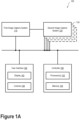
- Figure 1A illustrates a system 100, according to an example embodiment.
- the system 100 includes a first image capture system 110 and a second image capture system 120.
- the system 100 may be considered a stereoscopic imaging system.
- system 100 may include further image capture systems 130.
- system 100 may be considered a multiscopic imaging system.
- the image capture systems 110 and 120 may each include an image sensor, such as a charge-coupled device (CCD) or metal-oxide semiconductor (MOS) sensor.
- the respective image sensors may include millions of individual photosensors or pixels.
- the respective image sensors may be arranged in a 3:2 aspect ratio and may each include 3,872 ⁇ 2,592 pixels, or approximately ten million pixels.
- many other image sensors with different aspect ratios and more or fewer pixels are contemplated.
- the image capture systems 110 and 120 may be operable to provide digital photography and/or digital video information. That is, the image capture systems 110 and 120 may be configured as stereoscopic or multiscopic digital still cameras and/or digital video cameras. Image capture systems 110 and 120 may include various elements including, but not limited to, an aperture, shutter, recording surface (e.g., one or more image sensors), and/or lens.
- the plurality of image capture systems may be arranged in different orientations.
- the image capture systems 110 and 120 may be separated by a baseline distance and with parallel optical axes.
- the plurality of image capture systems may be arranged along a boundary of a shape.
- the shape may include a ring, a disk, or a sphere. Other shapes and/or arrangements of the plurality of image capture systems of system 100 are possible.
- the system 100 may include a user interface 140.
- the user interface 140 may include a display 142 and controls 144.
- User interface 140 may be configured to generate audible output(s) via a speaker, speaker jack, audio output port, audio output device, earphones, and/or other similar devices.
- the display 142 may include a viewfinder and/or another display configured to provide information about the system 100.
- the display 142 may include a multi-element light emitting diode (LED) display, a liquid crystal (LCD) display, a plasma display or another type of display.
- the display 142 may be a touchscreen. In such a scenario, a user of system 100 may be able to adjust settings of the system 100 by interacting with the display 142.
- the controls 144 may include buttons, switches, dials, or other types of controls with which a user may interact.
- the controls 144 may include a shutter button and controls operable to adjust focus, field of view, zoom, shutter speed, aperture, and/or ISO, among many other possibilities.
- the shutter button may be operable to trigger an image capture process in which one image frame is captured by each of the image capture systems 110 and 120 to form an image pair.
- the shutter button may be operable to trigger a plurality of still images or a video stream.
- some embodiments may include triggering the image capture process via other controls or via the controller 150.
- the image capture process may be triggered via a timer or remote trigger.
- Captured digital images may be represented as a one-dimensional, two-dimensional, or multi-dimensional array of pixels.
- Each pixel may be represented by one or more values that may encode the respective pixel's color and/or brightness.
- the Y channel may represent the brightness of a pixel
- the Cb and Cr channels may represent the blue chrominance and red chrominance, respectively, of the pixel.
- each of these channels may take values from 0 to 255.
- the brightness of a pixel may be represented by a 0 or a value near zero if the pixel is black or close to black, and by a 255 or a value near 255 if the pixel is white or close to white.
- the value of 255 is a non-limiting reference point, and some implementations may use different maximum values (e.g., 1023, 4095, etc.).
- RGB red-green-blue
- CYK cyan-magenta-yellow-key
- JPEG Joint Photographic Experts Group
- PNG Portable Network Graphics
- GIF Graphics Interchange Format
- the image capture systems 110 and 120 may be configured to capture image frames at a rate of 30 frames per second (FPS). However, image capture systems having greater or lesser frame rates are possible.
- FPS frames per second
- the image capture systems 110 and 120 may include a "burst" capture mode having a burst frame rate.
- the burst frame rate may include a capture frame rate that is faster than normal over a brief period of time.
- the image capture systems 110 and 120 may each be operable to provide burst image data, which may include two sets of ten image frames (one set from each image capture system) captured consecutively at 60 FPS.
- Other burst image frame amounts and other burst frame rates are possible.
- the image capture systems 110 and 120 may be communicatively and/or mechanically coupled so as to provide coordinated image capture. That is, respective image frames may be captured at substantially the same time, (e.g., in synchronicity) by image capture systems 110 and 120. The respective image frames captured at substantially the same time may be termed an image pair.
- the respective image frames need not be captured at the same time by the first image capture system 110 and the second image capture system 120. However, a relative capture time between the respective image frames may be measured, recorded, and used to more easily correlate and/or determine various image adjustments described herein.
- the image capture systems 110 and 120 may be substantially similar, differing only in physical location and/or orientation. However, in other embodiments, the image capture systems 110 and 120 may differ in other ways.
- the first image capture system 110 may include an image sensor optically coupled to a color filter array and the second image capture system 120 may include an image sensor without a color filter array (or vice versa).
- the color filter array may include a Bayer color filter or another type of filter configured to selectively absorb light based on its wavelength.
- the first image capture system 110 may include an image sensor optically coupled to a low pass filter and the second image capture system 120 may include an image sensor without a low pass filter (or vice versa).
- the first image capture system 110 may include an image sensor optically coupled to optics having a first focal length (e.g. 35mm) and the second image capture system may include an image sensor optically coupled to optics having a second focal length (e.g. 105mm), or vice versa.
- some or all of the image processing operations described herein may relate to a portion of the image frame. That is, image rectification, warping, denoising, and high-dynamic range processing may be applied to an "overlapping" portion of the image frames where the respective fields of view of the image capture systems overlap.
- the first image capture system 110 and the second image capture system 120 may be respectively operable as “left” and “right” image sensors (or vice versa) of a stereoscopic or binocular imaging system. That is, a combination of the first image capture system 110 and the second image capture system 120 may be configured to provide stereoscopic imaging information about a scene. In some embodiments, the combination of image capture systems 110 and 120 may provide information indicative of three-dimensional depth and/or information useful to provide visual depth perception.
- the image capture systems 110, 120, and/or 130 may include wearable cameras. Furthermore, any number of the image capture systems 110, 120, and/or 130 may be physically detached from the other image capture systems. That is, the image capture systems contemplated herein may be located in different locations. For example, the image capture systems contemplated herein may include a plurality of smartphone cameras located in different locations and operated by a plurality of users. Additionally or alternatively, one or more of the image capture systems may be in a fixed location (e.g., stabilized on a tripod) and one or other image capture systems may be mobile or moveable. Other combinations, orientations, and arrangements of the plurality of image capture systems are possible.
- the System 100 also includes a controller 150.
- the controller 150 may include one or more processors 152 and a memory 154.
- the controller 150 includes at least one programmable in-circuit serial programming (ICSP) microcontroller.
- the one or more processors 152 may include one or more general purpose processors (e.g., microprocessors) and/or one or more special purpose processors-e.g., digital signal processors (DSPs), graphics processing units (GPUs), floating point units (FPUs), network processors, or application-specific integrated circuits (ASICs).
- the memory 154 may be configured to store computer-readable program instructions.
- the memory 154 may include volatile and/or non-volatile storage components, such as optical, magnetic, organic, or other memory or disc storage, which may be integrated in whole or in part with the one or more processors 152.
- the memory 154 may be implemented using a single physical device (e.g., one optical, magnetic, organic or other memory or disc storage unit), while in other embodiments, the memory 154 can be implemented using two or more physical devices.
- the one or more processors 152 may be configured to execute the instructions so as to carry out operations.
- the operations may include adjustments and/or enhancements to one or more images captured by the image capture systems 110, 120, and/or 130.
- the controller 150 may be communicatively coupled to the first image capture system 110, the second image capture system 120, and/or the other image capture systems 130 via a communication interface.
- the communication interface may include one or more wireless interfaces and/or one or more wired interfaces, which allow the controller 150 to communicate with the other elements of system 100 via one or more networks.
- wireless interfaces may provide for communication under one or more wireless communication protocols, such as Bluetooth, WiFi (e.g., an IEEE 802.11 protocol), Long-Term Evolution (LTE), WiMAX (e.g., an IEEE 802.16 standard), a radio-frequency ID (RFID) protocol, near-field communication (NFC), and/or other wireless communication protocols.
- RFID radio-frequency ID
- NFC near-field communication
- Wired interfaces may include an Ethernet interface, a Universal Serial Bus (USB) interface, or similar interface to communicate via a wire, a twisted pair of wires, a coaxial cable, an optical link, a fiber-optic link, or other type of physical connection. Also, there may be one or more routers, switches, and/or other devices or networks making up at least a part of the communication interface.
- USB Universal Serial Bus
- Figure 1A illustrates the controller 150 as being schematically apart from the first image capture system 110 and the second image capture system 120
- the controller 150 may be physically located at, or incorporated into, one or more elements of system 100.
- the controller 150 may be incorporated into the first image capture system 110.
- the controller 150 may be incorporated into the second image capture system 120.
- the controller 150 may be distributed among the first image capture system 110 and the second image capture system 120.
- the controller 150 may include a distributed computing network and/or a cloud computing network.
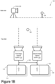
- Figure 1B illustrates side and top views of a system 160, according to an example embodiment.
- the system 160 may include some or all elements of system 100, as illustrated and described in reference to Figure 1A .
- system 160 may include the first image capture system 110 and the second image capture system 120.
- a combination of the image capture systems may be arranged to view a scene.
- the system 160 may be configured to provide images (e.g., digital image information) based on the scene.
- the first image capture system 110 and the second image capture system 120 may be arranged apart from one another at a baseline separation 162, or baseline distance.
- the baseline separation 162 may be based on a distance between the respective optical axes of the first image capture system 110 and the second image capture system 120.
- the optical axes of the first image capture system 110 and the second image capture system 120 may be parallel. However, in some embodiments, the optical axes need not be parallel. Furthermore, at least one of the optical axes may be adjustable.
- the scene may include an object 164.
- the first image capture system 110 and the second image capture system 120 may provide respective image data 114 and 124.
- the image data 114 and 124 may include image information about the scene and object 164.
- the image data 114 and 124 may differ at least because of the different physical positions of the first image capture system 110 and the second image capture system 120.
- the relative position of the object 164 may be different within the image frames 112 and 122. That is, object 164 may be included in both image frames 112 and 122. However, the object 164 may appear in a different relative position in the image frames 112 and 122.
- the difference in the relative position of object 164 may be considered the stereo disparity for that particular image feature.
- Other image features corresponding to other distances and/or positions from the respective image capture systems may relate to other values of stereo disparity.
- Figure 1B includes a scene that only includes object 164, it is understood that a simplistic description is provided for explanatory purposes only.
- the image capture systems 110 and 120 may be configured to capture more complex scenes.
- system 160 may be configured to image a variety of different scenes that may include any number of objects or features (or lack of such objects or features).
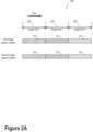
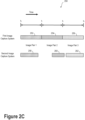
- FIGS. 2A , 2B , and 2C illustrate various image capture scenarios contemplated within the scope of the present disclosure.
- FIG. 2A illustrates an image capture scenario 200, according to an example embodiment.
- Image capture scenario 200 includes a first image capture system and a second image capture system, which may be similar or identical to the image capture systems 110 and 120 illustrated and described in reference to Figures 1A and 1B .
- the first image capture system may begin capturing image frame 210. That is, an image sensor of the first image capture system may collect photons from a scene for an exposure duration 202 between t 0 and t 1 .
- the second image capture system may begin capturing image frame 220.
- the second image capture system may collect photons from the scene for an exposure duration 202 between t 0 and t 1 .
- the combination of image frame 210 and image frame 220 may be considered image pair 1.
- Subsequent image pairs may be captured by the plurality of image capture systems. That is, image pair 2, which includes image frames 212 and 222, may be captured over an exposure duration 204 between t 1 and t 2 . Furthermore, image pair 3 that includes image frames 214 and 224 may be captured over an exposure duration 206 between t 2 and t 3 . It is understood that the specific timing sequences and exposure durations may vary.
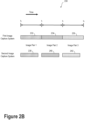
- Figure 2B illustrates an image capture scenario 230, according to an example embodiment.
- the image frames of the respective image pairs need not be captured with the same exposure duration.
- image frame 232. may be captured by the first image capture system over an exposure duration from t 0 to t 1 .
- image frame 238 may be captured over a shorter exposure duration. Nonetheless, image frames 232 and 238 may be considered image pair 1 for the purposes of the present disclosure.
- one or more images from each respective image pair may have a different brightness with respect to a base, or reference, image.
- analog and/or digital gain may optionally be applied at the respective image sensor, or digital gain may be applied to the respective image(s) so as to provide a "total exposure" (e.g., a product of exposure time and gain) similar to that of the base image.
- total exposure e.g., a product of exposure time and gain
- the various image frames may be more easily compared and/or combined and image rectification, stereo warping, and denoising may still be applied to the constituent image frames.
- image frames 240 and 242 may have different exposure durations compared to corresponding image frames 234 and 236.
- Figure 2C illustrates an image capture scenario 250, according to an example embodiment.
- image frames 258, 260, and 262 may have different exposure duration and/or may differ in time (e.g., the respective images may be initiated and/or end at different times) compared to corresponding image frames 252, 254, and 256. Nonetheless image frames (252 & 258), (254 & 260), and (256 & 262) may be considered image pairs within the scope of the present disclosure.
- Figure 3 illustrates a flowchart 300, according to an example embodiment.
- the controller 150 may be configured to carry out various operations.
- the various blocks of flowchart 300 may illustrate some or all such operations.
- the blocks of flowchart 300 illustrate and describe operations that may involve elements of systems 100 and/or 160 as illustrated and described in relation to Figures 1A and 1B .
- the blocks of flowchart 300 are illustrated as having a particular order, one or more blocks may be removed, added, repeated, completed concurrently with another block, and/or completed out of order.
- the controller 150 is operable to receive burst image data from the image capture systems 110 and 120.
- the burst image data includes first image data from the first image capture system 110 and second image data from the second image capture system 120.
- the burst image data includes a plurality of image pairs (e.g., 10 image pairs).
- the controller 150 is configured to determine at least one rectifying homography function based on the burst image data.
- the at least one rectifying homography function is configured to align corresponding image portions of the at least one image pair.
- the at least one rectifying homography function may be determined based on a calibration procedure before normal use.
- the calibration procedure may provide an essential matrix, which may describe the geometrical relationship between the image capture systems 110 and 120.
- the calibration procedure may provide information about an epipolar geometry of the image capture systems 110 and 120.
- information may include the corresponding epipolar lines of the image capture systems 110 and 120.
- Information about the epipolar geometry may improve image processing efficiency at least because knowledge of the epipolar lines may reduce the possible search parameters when trying to align a target image with a reference image (e.g., searching for a corresponding object/feature along a 1D line versus within a 2D area).
- the at least one rectifying homography function may be determined "on the fly” based on, for example, comparisons between the frames of an image pair, such as a corresponding feature in both frames of the image pair.
- one or more fundamental matrices between the two cameras may be determined based on the corresponding features of the image pair.
- the fundamental matrices may be determined based on minimizing the disparity or least-square difference of corresponding points on the horizontal axis of the image pair.
- the rectifying homography function(s) may include a linear transformation.
- the linear transformation may include a rotational transformation, a scaling transformation, and/or image skew transformation.
- the rotational transformation may include rotating a first image frame with respect to a second image frame, or vice versa.
- the scaling transformation may include enlarging or reducing a first image frame with respect to a second image frame, or vice versa.
- the image skew transformation may include adjusting the image for z-axis tilt. Other types of image transformations are contemplated so as to align or otherwise rectify frames of an image pair and/or burst image data generally.
- the rectifying homography function(s) may be operable to align image frames based on a calculation or an estimate of the epipolar geometry of a scene. Namely, one or both of the image frames are transformed to emulate having a common image plane. It is understood that the rectifying homography function(s) may be determined using a variety of image processing techniques. Each such image processing technique is contemplated herein.
- the controller 150 is operable to adjust at least one of the first image data or the second image data according to the determined at least one rectifying homography function. That is, the controller 150 may align the first image data with the second image data by adjusting the relative rotation, skew, scale, etc. In some embodiments, one of the first image data or the second image data may be modified according to the at least one rectifying homography function. In some other embodiments, both of the first image data and the second image data are modified according to the at least one rectifying homography function.
- adjusting the first and/or the second image data according to the at least one rectifying homography function may provide a "rough alignment" of the image data prior to further adjusting the image data according to optical flow or other image processing algorithms.
- the controller 150 is operable to carry out a determination of the stereo disparity of the burst image data.
- the stereo disparity may include a distance between two corresponding points in a "left" and "right” image of a stereo image pair.
- the stereo disparity is determined by the controller based at least on the baseline distance.
- the stereo disparity may be determined based on a comparison between the left and right images of the stereo image pair.
- the determination of the stereo disparity may include estimating a parallax function based on the first image data, the second image data, and the baseline distance. In other words, the stereo disparity may be determined as part of a three-dimensional image processing method.
- the controller 150 may be configured to provide a disparity image based on the comparison between the left and right images of the stereo image pair.
- the disparity image may include an image frame having pixel brightness levels based on the geometrical disparity between corresponding features in the left and right image frames of the stereo image pair. Additionally or alternatively, the controller 150 may be configured to provide a disparity map based on the comparison between the image frames of the stereo image pair.
- the controller 150 may receive range data via a LIDAR, RADAR, ultrasonic sensor or another type of distance-measuring system. The controller 150 may utilize this range data to determine, at least in part, the stereo disparity.
- the controller 150 is operable to "warp" or otherwise modify at least one image of each image pair according to the determined stereo disparity. That is, the controller 150 adjusts at least one image of each image pair such that it substantially matches the corresponding image of the image pair.
- image adjustments includes applying an inverse of the determined stereo disparity and/or the estimated parallax function to at least one of the first image data or the second image data.
- warping of the burst image data forms a warped image stack.
- the warped image stack includes image frames that are substantially similar to one another with the possible exception of object motion, camera motion, and/or image noise.
- image adjustments may include moving one or more pixels in a target image based on corresponding locations (e.g., correctly-aligned pixels) in a reference image.
- an optical flow map of the scene may be provided.
- the optical flow map may include, for example, a relative distance and/or direction for each pixel moved in the target image based on the corresponding correctly-aligned pixels in the reference image.
- the optical flow map may be used to provide a depth map of the scene. For example, the depth map may be based on the baseline distance and/or the field of view of the image capture system(s).
- the controller 150 is configured to remove noise from the warped image stack. That is, the controller 150 applies a burst denoising algorithm to the warped image stack to generate at least one output image.
- the at least one output image may include less shot noise or other types of image noise.
- the burst denoising algorithm includes determining a weighted average of the warped image stack.
- the weighted average may include a per-pixel average of corresponding pixels of the warped image stack.
- the weighted average may be based on corresponding pixel intensity, color, and/or luminosity, among other possibilities.
- the burst denoising algorithm may include a low pass filter and/or a Fast Fourier Transform (FFT).
- FFT Fast Fourier Transform
- other embodiments may include a burst denoising algorithm that identifies similar pixel regions (e.g. based on color, brightness, etc.) and applies filtering and/or averaging to those regions.
- a Wiener filter may be used to filter undesirable noise from the warped image stack.
- the Wiener filter may reduce or minimize the mean square error between an estimated random process (e.g., the shot noise) and the desired image.
- other types of image denoising filters are possible, such as Block-Matching and 3D filtering (BM3D) or non-local means. It is understood that a variety of other denoising techniques and algorithms are possible and contemplated herein.
- LDR imaging Some pixel encodings use 8 bits to represent the brightness of each pixel. Doing so is referred to as low dynamic range (LDR) imaging. As a result, only 256 levels of brightness may be supported. However, real-world scenes often exhibit a wider dynamic range of brightness than can be reasonably represented by LDR imaging. For example, a scene of an individual standing in a dark room in front of a window may include both extremely bright regions and extremely dark regions. However, use of LDR imaging to capture an image of such a scene may result in loss of detail in the bright region and/or the dark region based on the exposure length with which the image was captured.
- a short exposure length may result in a reasonably accurate representation of the bright regions of a scene, but underexposure of the dark regions.
- a long exposure length may result in a reasonably accurate representation of the dark regions, but may overexpose the bright regions.
- the features in the room may appear properly-exposed, but the features outside the window may appear whitewashed. But if the exposure length is too short, the features outside the window may appear normal but the features in the room may appear darkened. Either of these outcomes is undesirable.
- a first image frame may be captured with a first exposure length, which may properly expose a sky and a cloud portion of the scene, but may result in an improper exposure (e.g., an underexposure) of a person and the surrounding room.
- a second image frame may be captured with a second exposure length, which may properly expose the person and the surrounding room, but may result in an improper exposure (e.g., an overexposure) of the sky and the cloud portions of the scene.
- the controller 150 may be operable to apply high dynamic range (HDR) processing to the warped image stack and/or one or more output images.
- HDR high dynamic range
- properly-exposed pixels of a first image frame of the image stack may be combined with pixels in a second image frame of the image stack that correspond to improperly-exposed pixels in the first image frame.
- properly-exposed sky and cloud portions from the first image frame may be combined with properly-exposed person and room portions from the second image frame.
- the resulting composite image may reproduce the details of both the bright and dark regions of the scene reasonably well.
- Combining pixels from captured images to form the composite image may be accomplished in a number of ways. For example, a pixel-by-pixel combination of images may be formed by assigning weights to the pixels of each image according to, for instance the brightness of the pixels. Then, depending on its weight, a particular pixel may be included or excluded from the final image. Alternatively, two or more LDR images may be combined into an HDR image, and the HDR image may then be tone mapped so that its brightness falls within a range commensurate with the display abilities of convention video output devices. However, other methods of combining pixels from captured images may be used instead for the embodiments herein.
- HDR processing may be performed based on the image frames captured using automatic exposure bracketing (AEB). That is, the warped image stack may include image frames having a range of exposure durations. As such, an HDR output image may be provided based on the properly exposed regions from a plurality of image frames in the warped image stack.
- the burst image data may include image frames captured over 18 exposure values (EV). Other exposure bracketing ranges are possible.
- HDR high definition digital versatile disc
- exposure, brightness, gamma, color, or other aspects of an output image may be adjusted so as to reduce over-exposed and under-exposed regions.
- the shadows of the output image may be enhanced and the highlights of the output image may be reduced.
- one or more output images may be tone-mapped to reduce the dynamic range or contrast ratio of the output image while retaining localized contrast.
- Other ways to reduce over- and under-exposed regions of an image while retaining image detail are contemplated herein.
- the controller 150 may be operable to analyze the image data so as to group, designate, and/or segregate pixels within each image frame according to "tiles" having image pixels with similar characteristics.
- an image frame may be analyzed to determine similar tiles or regions according to one or more image characteristics, such as pixel brightness, color, tone, shape, edge, etc.
- image characteristics such as pixel brightness, color, tone, shape, edge, etc.
- a pixel area with a high brightness e.g., a sky
- a pixel area with a lower brightness e.g., the ground
- a single image frame may include tens, hundreds, thousands, or more tiles.
- the burst image data may be tiled in a manner similar to that described above.
- the burst image data may include image frames with tiles having a similar shape and position within the respective image frames. Matching corresponding tiles between the respective image frames may be substantially faster than searching over the entire number of pixels.
- any of the image processing operations described herein may be carried out based on a per-tile basis. That is, the at least one rectifying homography function may be determined based on aligning the corresponding tiles in the at least one image pair. Furthermore, the stereo disparity may be determined by comparing the relative location of similar tiles in the image frames of the stereo image pair(s). Additionally, the burst denoising algorithm may be carried out by comparing the corresponding tiles of each image frame of the warped image stack. Yet further, the HDR processing may include combining correctly-exposed tiles from various image frames of the warped image stack.
- image processing based on handling tiles may provide improvements in speed and image quality over image processing on a per-pixel basis.
- tiled image processing may reduce or eliminate "ghosting", blurring image artifacts, and/or artifacts at the edges of tile boundaries.
- Figure 4 illustrates a method 400, according to an example embodiment.
- Some or all blocks of method 400 may involve elements of system 100 and/or system 160 as illustrated and described in reference to Figures 1A and 1B .
- computer readable medium such as a storage device including a disk, hard drive, or other storage medium.
- the computer readable medium can also include non-transitory computer readable media such as computer-readable media that store data for short periods of time like register memory, processor cache, and random access memory (RAM).
- the computer readable media can also include non-transitory computer readable media that store program code and/or data for longer periods of time.
- the computer readable media may include secondary or persistent long term storage, like read only memory (ROM), optical or magnetic disks, compact-disc read only memory (CD-ROM), for example.
- the computer readable media can also be any other volatile or non-volatile storage systems.
- a computer readable medium can be considered a computer readable storage medium, for example, or a tangible storage device.
- Block 412 includes generating at least one output image according to a burst denoising algorithm.
- the burst denoising algorithm includes determining a weighted average of the warped image stack.
- the weighted average includes a per-pixel average of corresponding pixels of the warped image stack.
- the method may include applying a high dynamic range (HDR) function to the at least one output image to provide at least one HDR output image.
- HDR high dynamic range
- first image capture system and the second image capture system may provide different respective images based on, for example, the image capture systems having a different image sensor, optical path, optical transfer function (OTF), and/or field of view.
- OTF optical transfer function
- the methods and processes described herein may still be applied. For example, image alignment, warping, and denoising processes may be applied to burst image data upon compensating for the relevant difference(s) between the images from the respective image capture systems.
- the first image capture system may include an image sensor optically coupled to a color filter array and the second image capture system may include an image sensor without a color filter array.
- An optional image compensation block or step may include adjusting a brightness level of at least some pixels of image frames from one or both image capture systems based on, for example, a wavelength dependent optical transfer function of the color filter array.
- the first image capture system may include an image sensor optically coupled to a low pass filter and the second image capture system may include an image sensor without a low pass filter.
- an optional image compensation block or step may include adjusting a brightness level, or another aspect of the image information, of the image frames based on a wavelength dependent optical transfer function of the low pass filter.
- the first image capture system may include an image sensor optically coupled to optics having, for example, a first focal length and the second image capture system may include an image sensor optically coupled to optics having a second focal length different from the first focal length.
- an optional image compensation block or step may include adjusting one or both sets of image data based on the differences in the optics in the respective image capture devices.
- the image data may be adjusted based on compensating for different field of view, vignetting, distortion (e.g., barrel, pin cushion, or mustache distortion), and chromatic aberration between the two different sets of optics.
- a difference in barrel distortion may be compensated using a Brown-Conrady distortion correction algorithm. It is understood that a variety of other image correction algorithms may be implemented so as to compensate for the different optical scenarios described above. All such other image correction algorithms are contemplated within the scope of the present disclosure.
- a step or block that represents a processing of information can correspond to circuitry that can be configured to perform the specific logical functions of a herein-described method or technique.
- a step or block that represents a processing of information can correspond to a module, a segment, or a portion of program code (including related data).
- the program code can include one or more instructions executable by a processor for implementing specific logical functions or actions in the method or technique.
- the program code and/or related data can be stored on any type of computer readable medium such as a storage device including a disk, hard drive, or other storage medium.
- the computer readable medium can also include non-transitory computer readable media such as computer-readable media that store data for short periods of time like register memory, processor cache, and random access memory (RAM).
- the computer readable media can also include non-transitory computer readable media that store program code and/or data for longer periods of time.
- the computer readable media may include secondary or persistent long term storage, like read only memory (ROM), optical or magnetic disks, compact-disc read only memory (CD-ROM), for example.
- the computer readable media can also be any other volatile or non-volatile storage systems.
- a computer readable medium can be considered a computer readable storage medium, for example, or a tangible storage device.
Landscapes
- Engineering & Computer Science (AREA)
- Multimedia (AREA)
- Signal Processing (AREA)
- Physics & Mathematics (AREA)
- General Physics & Mathematics (AREA)
- Theoretical Computer Science (AREA)
- Computer Vision & Pattern Recognition (AREA)
- Studio Devices (AREA)
- Testing, Inspecting, Measuring Of Stereoscopic Televisions And Televisions (AREA)
- Measurement Of Optical Distance (AREA)
Applications Claiming Priority (2)
| Application Number | Priority Date | Filing Date | Title |
|---|---|---|---|
| US14/961,102 US9762893B2 (en) | 2015-12-07 | 2015-12-07 | Systems and methods for multiscopic noise reduction and high-dynamic range |
| PCT/US2016/064290 WO2017100061A1 (en) | 2015-12-07 | 2016-11-30 | Systems and methods for multiscopic noise reduction and high-dynamic range |
Publications (3)
| Publication Number | Publication Date |
|---|---|
| EP3335420A1 EP3335420A1 (en) | 2018-06-20 |
| EP3335420A4 EP3335420A4 (en) | 2019-07-03 |
| EP3335420B1 true EP3335420B1 (en) | 2025-01-01 |
Family
ID=58800470
Family Applications (1)
| Application Number | Title | Priority Date | Filing Date |
|---|---|---|---|
| EP16873617.1A Active EP3335420B1 (en) | 2015-12-07 | 2016-11-30 | Systems and methods for multiscopic noise reduction and high-dynamic range |
Country Status (6)
| Country | Link |
|---|---|
| US (4) | US9762893B2 (enExample) |
| EP (1) | EP3335420B1 (enExample) |
| JP (2) | JP6818015B2 (enExample) |
| KR (2) | KR101991474B1 (enExample) |
| CN (2) | CN110225330A (enExample) |
| WO (1) | WO2017100061A1 (enExample) |
Families Citing this family (29)
| Publication number | Priority date | Publication date | Assignee | Title |
|---|---|---|---|---|
| US10410398B2 (en) * | 2015-02-20 | 2019-09-10 | Qualcomm Incorporated | Systems and methods for reducing memory bandwidth using low quality tiles |
| US9762893B2 (en) * | 2015-12-07 | 2017-09-12 | Google Inc. | Systems and methods for multiscopic noise reduction and high-dynamic range |
| WO2018048838A1 (en) | 2016-09-06 | 2018-03-15 | Apple Inc. | Still image stabilization/optical image stabilization synchronization in multi-camera image capture |
| US10499042B2 (en) * | 2017-04-01 | 2019-12-03 | Intel Corporation | Barreling and compositing of images |
| US10863105B1 (en) * | 2017-06-27 | 2020-12-08 | Amazon Technologies, Inc. | High dynamic range imaging for event detection and inventory management |
| CN107730464B (zh) * | 2017-10-09 | 2021-03-30 | 四川大学 | 基于块匹配的图像降噪并行算法 |
| WO2019164497A1 (en) * | 2018-02-23 | 2019-08-29 | Sony Mobile Communications Inc. | Methods, devices, and computer program products for gradient based depth reconstructions with robust statistics |
| CN111837144B (zh) | 2018-03-13 | 2024-07-26 | 奇跃公司 | 使用机器学习的增强图像深度感测 |
| CN108717690B (zh) * | 2018-05-21 | 2022-03-04 | 电子科技大学 | 一种高动态范围图片的合成方法 |
| US11216923B2 (en) | 2018-05-23 | 2022-01-04 | Samsung Electronics Co., Ltd. | Apparatus and method for successive multi-frame image denoising |
| CN108924434B (zh) * | 2018-06-29 | 2020-08-18 | 宁波大学 | 一种基于曝光变换的立体高动态范围图像合成方法 |
| US10902556B2 (en) | 2018-07-16 | 2021-01-26 | Nvidia Corporation | Compensating for disparity variation when viewing captured multi video image streams |
| KR102525000B1 (ko) | 2018-08-08 | 2023-04-24 | 삼성전자 주식회사 | 복수의 이미지들이 합성된 이미지를 깊이 정보에 기반하여 흐림 처리하는 전자 장치 및 상기 전자 장치의 구동 방법 |
| JP6970835B2 (ja) * | 2018-09-28 | 2021-11-24 | 株式会社Pfu | 画像処理装置、制御方法及び制御プログラム |
| KR20250126853A (ko) | 2018-12-20 | 2025-08-25 | 스냅 인코포레이티드 | 입체 이미지들을 생성하기 위한 듀얼 카메라들을 갖는 가요성 안경류 디바이스 |
| GB2588616B (en) * | 2019-10-29 | 2021-10-27 | Visidon Oy | Image processing method and apparatus |
| US10965931B1 (en) | 2019-12-06 | 2021-03-30 | Snap Inc. | Sensor misalignment compensation |
| CN111242860B (zh) * | 2020-01-07 | 2024-02-27 | 影石创新科技股份有限公司 | 超级夜景图像的生成方法、装置、电子设备及存储介质 |
| EP3889880B1 (en) * | 2020-03-30 | 2022-03-23 | Axis AB | Wearable camera noise reduction |
| CN117372248A (zh) | 2020-05-17 | 2024-01-09 | 核心光电有限公司 | 全视场参考图像的图像拼接 |
| US20230239452A1 (en) * | 2020-06-04 | 2023-07-27 | Advanced Farm Technologies, Inc. | Color stereo camera systems with global shutter synchronization |
| KR102801383B1 (ko) | 2020-07-24 | 2025-04-29 | 삼성전자주식회사 | 영상 복원 장치 및 방법 |
| KR102860336B1 (ko) | 2021-02-08 | 2025-09-16 | 삼성전자주식회사 | 연사 영상 기반의 영상 복원 방법 및 장치 |
| US12439163B2 (en) | 2021-05-19 | 2025-10-07 | Google Llc | Mobile device support for capture and synthesis of extreme low-light video |
| US20230013884A1 (en) * | 2021-07-14 | 2023-01-19 | Cilag Gmbh International | Endoscope with synthetic aperture multispectral camera array |
| US12568314B2 (en) | 2022-02-16 | 2026-03-03 | Samsung Electronics Co., Ltd. | Image signal processor, method of operating the image signal processor, and application processor including the image signal processor |
| US12373922B2 (en) | 2022-10-07 | 2025-07-29 | Mohamed bin Zayed University of Artificial Intelligence | System and method for burst image restoration and enhancement |
| US12412252B2 (en) | 2023-01-04 | 2025-09-09 | Samsung Electronics Co., Ltd. | System and method for scene-adaptive denoise scheduling and efficient deghosting |
| US20260004402A1 (en) * | 2024-06-30 | 2026-01-01 | Gopro, Inc. | Methods and apparatus for frame denoising |
Citations (1)
| Publication number | Priority date | Publication date | Assignee | Title |
|---|---|---|---|---|
| US20130064470A1 (en) * | 2011-09-14 | 2013-03-14 | Canon Kabushiki Kaisha | Image processing apparatus and image processing method for reducing noise |
Family Cites Families (46)
| Publication number | Priority date | Publication date | Assignee | Title |
|---|---|---|---|---|
| JP3733359B2 (ja) * | 1996-04-05 | 2006-01-11 | 松下電器産業株式会社 | 視差推定方法、画像伝送方法、画像表示方法、多視点画像伝送方法、多視点画像復元方法および視差推定装置 |
| JP3769850B2 (ja) * | 1996-12-26 | 2006-04-26 | 松下電器産業株式会社 | 中間視点画像生成方法および視差推定方法および画像伝送方法 |
| JP3912639B2 (ja) * | 1998-07-17 | 2007-05-09 | 日本ビクター株式会社 | 3次元画像処理装置 |
| JP2000102040A (ja) * | 1998-09-28 | 2000-04-07 | Olympus Optical Co Ltd | 電子ステレオカメラ |
| JP2003209858A (ja) * | 2002-01-17 | 2003-07-25 | Canon Inc | 立体画像生成方法及び記録媒体 |
| JP2004120527A (ja) * | 2002-09-27 | 2004-04-15 | Fuji Photo Film Co Ltd | 2眼式デジタルカメラ |
| JP4017579B2 (ja) * | 2003-09-19 | 2007-12-05 | 株式会社ソニー・コンピュータエンタテインメント | 撮影補助器、画像処理方法、画像処理装置、コンピュータプログラム、プログラムを格納した記録媒体 |
| JP2006093860A (ja) * | 2004-09-21 | 2006-04-06 | Olympus Corp | 2眼撮像系を搭載したカメラ |
| US7587099B2 (en) | 2006-01-27 | 2009-09-08 | Microsoft Corporation | Region-based image denoising |
| JP4665781B2 (ja) * | 2006-02-02 | 2011-04-06 | カシオ計算機株式会社 | 撮像装置、画像処理方法及びプログラム |
| JP4748398B2 (ja) * | 2007-06-15 | 2011-08-17 | 富士フイルム株式会社 | 撮像装置、撮像方法及びプログラム |
| JP4828506B2 (ja) * | 2007-11-05 | 2011-11-30 | 日本電信電話株式会社 | 仮想視点画像生成装置、プログラムおよび記録媒体 |
| US8866920B2 (en) * | 2008-05-20 | 2014-10-21 | Pelican Imaging Corporation | Capturing and processing of images using monolithic camera array with heterogeneous imagers |
| JP2009284188A (ja) * | 2008-05-22 | 2009-12-03 | Panasonic Corp | カラー撮像装置 |
| JP5444651B2 (ja) * | 2008-07-16 | 2014-03-19 | カシオ計算機株式会社 | カメラ装置、その撮影方法と撮影制御プログラム |
| JP2010147812A (ja) * | 2008-12-18 | 2010-07-01 | Fujifilm Corp | 複眼カメラ及び画像処理方法 |
| US8090251B2 (en) * | 2009-10-13 | 2012-01-03 | James Cameron | Frame linked 2D/3D camera system |
| CN110798586A (zh) * | 2010-02-19 | 2020-02-14 | 株式会社尼康 | 电子设备 |
| US8588551B2 (en) * | 2010-03-01 | 2013-11-19 | Microsoft Corp. | Multi-image sharpening and denoising using lucky imaging |
| EP2549762B1 (en) * | 2010-03-19 | 2017-05-03 | Panasonic Intellectual Property Management Co., Ltd. | Stereovision-image position matching apparatus, stereovision-image position matching method, and program therefor |
| CN102812712B (zh) * | 2010-03-24 | 2015-04-08 | 富士胶片株式会社 | 图像处理设备和图像处理方法 |
| KR101661215B1 (ko) * | 2010-08-16 | 2016-09-30 | 삼성전자주식회사 | 영상 처리 방법 및 영상 처리 장치 |
| JP2012216939A (ja) * | 2011-03-31 | 2012-11-08 | Fujifilm Corp | 画像処理装置、画像処理方法及びプログラム |
| JP5863280B2 (ja) * | 2011-05-24 | 2016-02-16 | キヤノン株式会社 | 撮像装置、画像処理方法及びプログラム |
| JP5917054B2 (ja) * | 2011-09-12 | 2016-05-11 | キヤノン株式会社 | 撮像装置、画像データ処理方法、およびプログラム |
| JP2013090129A (ja) * | 2011-10-18 | 2013-05-13 | Sony Corp | 画像処理装置、および画像処理方法、並びにプログラム |
| KR101854188B1 (ko) * | 2011-10-25 | 2018-05-08 | 삼성전자주식회사 | 3차원 영상 획득 장치 및 3차원 영상 획득 장치에서 깊이 정보 산출 방법 |
| JP6031670B2 (ja) * | 2011-12-09 | 2016-11-24 | パナソニックIpマネジメント株式会社 | 撮像装置 |
| JP2013162272A (ja) * | 2012-02-03 | 2013-08-19 | Olympus Imaging Corp | 撮像装置 |
| JP5992184B2 (ja) * | 2012-03-09 | 2016-09-14 | 株式会社トプコン | 画像データ処理装置、画像データ処理方法および画像データ処理用のプログラム |
| US20140009462A1 (en) * | 2012-04-17 | 2014-01-09 | 3Dmedia Corporation | Systems and methods for improving overall quality of three-dimensional content by altering parallax budget or compensating for moving objects |
| US9526069B2 (en) | 2012-04-20 | 2016-12-20 | Qualcomm Incorporated | Early initiation of dormancy of a radio connection |
| JP2015521411A (ja) * | 2012-05-01 | 2015-07-27 | ペリカン イメージング コーポレイション | πフィルタ群を用いてパターン化されたカメラモジュール |
| JP2014022806A (ja) * | 2012-07-13 | 2014-02-03 | Sharp Corp | 撮像装置および撮像装置制御方法 |
| CN107346061B (zh) * | 2012-08-21 | 2020-04-24 | 快图有限公司 | 用于使用阵列照相机捕捉的图像中的视差检测和校正的系统和方法 |
| US8866927B2 (en) | 2012-12-13 | 2014-10-21 | Google Inc. | Determining an image capture payload burst structure based on a metering image capture sweep |
| US9633442B2 (en) * | 2013-03-15 | 2017-04-25 | Fotonation Cayman Limited | Array cameras including an array camera module augmented with a separate camera |
| JP5887303B2 (ja) * | 2013-06-19 | 2016-03-16 | 株式会社 日立産業制御ソリューションズ | 画像信号処理装置,撮像装置および画像処理プログラム |
| US9615012B2 (en) * | 2013-09-30 | 2017-04-04 | Google Inc. | Using a second camera to adjust settings of first camera |
| EP2887642A3 (en) * | 2013-12-23 | 2015-07-01 | Nokia Corporation | Method, apparatus and computer program product for image refocusing for light-field images |
| KR101652658B1 (ko) | 2014-02-07 | 2016-08-30 | 가부시키가이샤 모르포 | 화상 처리 장치, 화상 처리 방법, 화상 처리 프로그램 및 기록 매체 |
| JP6376618B2 (ja) * | 2014-05-15 | 2018-08-22 | 華為技術有限公司Huawei Technologies Co.,Ltd. | マルチフレームノイズ低減方法および端末 |
| JP2015144475A (ja) * | 2015-03-11 | 2015-08-06 | キヤノン株式会社 | 撮像装置、撮像装置の制御方法、プログラム及び記憶媒体 |
| US10237473B2 (en) | 2015-09-04 | 2019-03-19 | Apple Inc. | Depth map calculation in a stereo camera system |
| US10284835B2 (en) | 2015-09-04 | 2019-05-07 | Apple Inc. | Photo-realistic shallow depth-of-field rendering from focal stacks |
| US9762893B2 (en) * | 2015-12-07 | 2017-09-12 | Google Inc. | Systems and methods for multiscopic noise reduction and high-dynamic range |
-
2015
- 2015-12-07 US US14/961,102 patent/US9762893B2/en active Active
-
2016
- 2016-11-30 KR KR1020187007208A patent/KR101991474B1/ko active Active
- 2016-11-30 CN CN201910370555.8A patent/CN110225330A/zh active Pending
- 2016-11-30 KR KR1020197017009A patent/KR102142641B1/ko active Active
- 2016-11-30 CN CN201680050125.2A patent/CN107925751B/zh active Active
- 2016-11-30 WO PCT/US2016/064290 patent/WO2017100061A1/en not_active Ceased
- 2016-11-30 EP EP16873617.1A patent/EP3335420B1/en active Active
- 2016-11-30 JP JP2018513646A patent/JP6818015B2/ja active Active
-
2017
- 2017-08-14 US US15/676,145 patent/US10187628B2/en active Active
-
2018
- 2018-12-20 US US16/226,643 patent/US10477185B2/en active Active
-
2019
- 2019-06-24 JP JP2019116364A patent/JP7186672B2/ja active Active
- 2019-11-11 US US16/680,474 patent/US10897609B2/en active Active
Patent Citations (1)
| Publication number | Priority date | Publication date | Assignee | Title |
|---|---|---|---|---|
| US20130064470A1 (en) * | 2011-09-14 | 2013-03-14 | Canon Kabushiki Kaisha | Image processing apparatus and image processing method for reducing noise |
Also Published As
| Publication number | Publication date |
|---|---|
| CN107925751B (zh) | 2019-06-04 |
| CN107925751A (zh) | 2018-04-17 |
| US10897609B2 (en) | 2021-01-19 |
| US9762893B2 (en) | 2017-09-12 |
| KR102142641B1 (ko) | 2020-08-07 |
| EP3335420A1 (en) | 2018-06-20 |
| CN110225330A (zh) | 2019-09-10 |
| WO2017100061A1 (en) | 2017-06-15 |
| KR20190071011A (ko) | 2019-06-21 |
| US10477185B2 (en) | 2019-11-12 |
| JP2019500762A (ja) | 2019-01-10 |
| KR20180030727A (ko) | 2018-03-23 |
| US20200084429A1 (en) | 2020-03-12 |
| US10187628B2 (en) | 2019-01-22 |
| JP7186672B2 (ja) | 2022-12-09 |
| EP3335420A4 (en) | 2019-07-03 |
| US20170347088A1 (en) | 2017-11-30 |
| US20170163966A1 (en) | 2017-06-08 |
| KR101991474B1 (ko) | 2019-06-20 |
| JP2019165506A (ja) | 2019-09-26 |
| US20190124319A1 (en) | 2019-04-25 |
| JP6818015B2 (ja) | 2021-01-20 |
Similar Documents
| Publication | Publication Date | Title |
|---|---|---|
| US10897609B2 (en) | Systems and methods for multiscopic noise reduction and high-dynamic range | |
| US9774880B2 (en) | Depth-based video compression | |
| CN108055452B (zh) | 图像处理方法、装置及设备 | |
| US9544574B2 (en) | Selecting camera pairs for stereoscopic imaging | |
| US12579669B2 (en) | Estimating depth based on iris size | |
| CN107959778B (zh) | 基于双摄像头的成像方法和装置 | |
| EP3053332B1 (en) | Using a second camera to adjust settings of first camera | |
| US20170111630A1 (en) | Depth-Assisted Focus in Multi-Camera Systems | |
| US9743015B2 (en) | Image capturing apparatus and method of controlling the same | |
| US10708486B2 (en) | Generation of a depth-artificial image by determining an interpolated supplementary depth through interpolation based on the original depths and a detected edge | |
| US20120050484A1 (en) | Method and system for utilizing image sensor pipeline (isp) for enhancing color of the 3d image utilizing z-depth information | |
| CN107948500A (zh) | 图像处理方法和装置 | |
| CN108024054A (zh) | 图像处理方法、装置及设备 | |
| CN108154514A (zh) | 图像处理方法、装置及设备 | |
| CN108156369A (zh) | 图像处理方法和装置 | |
| US20260129298A1 (en) | Field of View Correction Techniques for Shutterless Camera Systems | |
| WO2024076363A1 (en) | Field of view correction techniques for shutterless camera systems | |
| CN116630172A (zh) | 图像处理方法及装置、电子设备及计算机可读存储介质 |
Legal Events
| Date | Code | Title | Description |
|---|---|---|---|
| STAA | Information on the status of an ep patent application or granted ep patent |
Free format text: STATUS: THE INTERNATIONAL PUBLICATION HAS BEEN MADE |
|
| PUAI | Public reference made under article 153(3) epc to a published international application that has entered the european phase |
Free format text: ORIGINAL CODE: 0009012 |
|
| STAA | Information on the status of an ep patent application or granted ep patent |
Free format text: STATUS: REQUEST FOR EXAMINATION WAS MADE |
|
| 17P | Request for examination filed |
Effective date: 20180313 |
|
| AK | Designated contracting states |
Kind code of ref document: A1 Designated state(s): AL AT BE BG CH CY CZ DE DK EE ES FI FR GB GR HR HU IE IS IT LI LT LU LV MC MK MT NL NO PL PT RO RS SE SI SK SM TR |
|
| AX | Request for extension of the european patent |
Extension state: BA ME |
|
| DAV | Request for validation of the european patent (deleted) | ||
| DAX | Request for extension of the european patent (deleted) | ||
| RIC1 | Information provided on ipc code assigned before grant |
Ipc: H04N 9/79 20060101AFI20190218BHEP Ipc: H04N 13/239 20180101ALI20190218BHEP Ipc: H04N 13/25 20180101ALI20190218BHEP Ipc: H04N 9/64 20060101ALI20190218BHEP |
|
| A4 | Supplementary search report drawn up and despatched |
Effective date: 20190531 |
|
| RIC1 | Information provided on ipc code assigned before grant |
Ipc: H04N 13/25 20180101ALI20190524BHEP Ipc: H04N 9/79 20060101AFI20190524BHEP Ipc: H04N 9/64 20060101ALI20190524BHEP Ipc: H04N 13/239 20180101ALI20190524BHEP |
|
| STAA | Information on the status of an ep patent application or granted ep patent |
Free format text: STATUS: EXAMINATION IS IN PROGRESS |
|
| 17Q | First examination report despatched |
Effective date: 20200317 |
|
| REG | Reference to a national code |
Ref country code: DE Ref legal event code: R079 Free format text: PREVIOUS MAIN CLASS: H04N0009790000 Ipc: H04N0023680000 Ref document number: 602016090844 Country of ref document: DE |
|
| GRAP | Despatch of communication of intention to grant a patent |
Free format text: ORIGINAL CODE: EPIDOSNIGR1 |
|
| STAA | Information on the status of an ep patent application or granted ep patent |
Free format text: STATUS: GRANT OF PATENT IS INTENDED |
|
| RIC1 | Information provided on ipc code assigned before grant |
Ipc: H04N 23/68 20230101AFI20240611BHEP |
|
| INTG | Intention to grant announced |
Effective date: 20240701 |
|
| GRAS | Grant fee paid |
Free format text: ORIGINAL CODE: EPIDOSNIGR3 |
|
| GRAA | (expected) grant |
Free format text: ORIGINAL CODE: 0009210 |
|
| STAA | Information on the status of an ep patent application or granted ep patent |
Free format text: STATUS: THE PATENT HAS BEEN GRANTED |
|
| P01 | Opt-out of the competence of the unified patent court (upc) registered |
Free format text: CASE NUMBER: APP_58497/2024 Effective date: 20241025 |
|
| AK | Designated contracting states |
Kind code of ref document: B1 Designated state(s): AL AT BE BG CH CY CZ DE DK EE ES FI FR GB GR HR HU IE IS IT LI LT LU LV MC MK MT NL NO PL PT RO RS SE SI SK SM TR |
|
| REG | Reference to a national code |
Ref country code: GB Ref legal event code: FG4D |
|
| REG | Reference to a national code |
Ref country code: DE Ref legal event code: R096 Ref document number: 602016090844 Country of ref document: DE |
|
| REG | Reference to a national code |
Ref country code: CH Ref legal event code: EP |
|
| REG | Reference to a national code |
Ref country code: IE Ref legal event code: FG4D |
|
| REG | Reference to a national code |
Ref country code: LT Ref legal event code: MG9D |
|
| REG | Reference to a national code |
Ref country code: NL Ref legal event code: MP Effective date: 20250101 |
|
| REG | Reference to a national code |
Ref country code: AT Ref legal event code: MK05 Ref document number: 1757521 Country of ref document: AT Kind code of ref document: T Effective date: 20250101 |
|
| PG25 | Lapsed in a contracting state [announced via postgrant information from national office to epo] |
Ref country code: NL Free format text: LAPSE BECAUSE OF FAILURE TO SUBMIT A TRANSLATION OF THE DESCRIPTION OR TO PAY THE FEE WITHIN THE PRESCRIBED TIME-LIMIT Effective date: 20250101 |
|
| PG25 | Lapsed in a contracting state [announced via postgrant information from national office to epo] |
Ref country code: FI Free format text: LAPSE BECAUSE OF FAILURE TO SUBMIT A TRANSLATION OF THE DESCRIPTION OR TO PAY THE FEE WITHIN THE PRESCRIBED TIME-LIMIT Effective date: 20250101 |
|
| PG25 | Lapsed in a contracting state [announced via postgrant information from national office to epo] |
Ref country code: PL Free format text: LAPSE BECAUSE OF FAILURE TO SUBMIT A TRANSLATION OF THE DESCRIPTION OR TO PAY THE FEE WITHIN THE PRESCRIBED TIME-LIMIT Effective date: 20250101 |
|
| PG25 | Lapsed in a contracting state [announced via postgrant information from national office to epo] |
Ref country code: ES Free format text: LAPSE BECAUSE OF FAILURE TO SUBMIT A TRANSLATION OF THE DESCRIPTION OR TO PAY THE FEE WITHIN THE PRESCRIBED TIME-LIMIT Effective date: 20250101 |
|
| PG25 | Lapsed in a contracting state [announced via postgrant information from national office to epo] |
Ref country code: IS Free format text: LAPSE BECAUSE OF FAILURE TO SUBMIT A TRANSLATION OF THE DESCRIPTION OR TO PAY THE FEE WITHIN THE PRESCRIBED TIME-LIMIT Effective date: 20250501 Ref country code: NO Free format text: LAPSE BECAUSE OF FAILURE TO SUBMIT A TRANSLATION OF THE DESCRIPTION OR TO PAY THE FEE WITHIN THE PRESCRIBED TIME-LIMIT Effective date: 20250401 |
|
| PG25 | Lapsed in a contracting state [announced via postgrant information from national office to epo] |
Ref country code: HR Free format text: LAPSE BECAUSE OF FAILURE TO SUBMIT A TRANSLATION OF THE DESCRIPTION OR TO PAY THE FEE WITHIN THE PRESCRIBED TIME-LIMIT Effective date: 20250101 |
|
| PG25 | Lapsed in a contracting state [announced via postgrant information from national office to epo] |
Ref country code: PT Free format text: LAPSE BECAUSE OF FAILURE TO SUBMIT A TRANSLATION OF THE DESCRIPTION OR TO PAY THE FEE WITHIN THE PRESCRIBED TIME-LIMIT Effective date: 20250502 Ref country code: LV Free format text: LAPSE BECAUSE OF FAILURE TO SUBMIT A TRANSLATION OF THE DESCRIPTION OR TO PAY THE FEE WITHIN THE PRESCRIBED TIME-LIMIT Effective date: 20250101 |
|
| PG25 | Lapsed in a contracting state [announced via postgrant information from national office to epo] |
Ref country code: BG Free format text: LAPSE BECAUSE OF FAILURE TO SUBMIT A TRANSLATION OF THE DESCRIPTION OR TO PAY THE FEE WITHIN THE PRESCRIBED TIME-LIMIT Effective date: 20250101 Ref country code: GR Free format text: LAPSE BECAUSE OF FAILURE TO SUBMIT A TRANSLATION OF THE DESCRIPTION OR TO PAY THE FEE WITHIN THE PRESCRIBED TIME-LIMIT Effective date: 20250402 |
|
| PG25 | Lapsed in a contracting state [announced via postgrant information from national office to epo] |
Ref country code: AT Free format text: LAPSE BECAUSE OF FAILURE TO SUBMIT A TRANSLATION OF THE DESCRIPTION OR TO PAY THE FEE WITHIN THE PRESCRIBED TIME-LIMIT Effective date: 20250101 |
|
| PG25 | Lapsed in a contracting state [announced via postgrant information from national office to epo] |
Ref country code: CZ Free format text: LAPSE BECAUSE OF FAILURE TO SUBMIT A TRANSLATION OF THE DESCRIPTION OR TO PAY THE FEE WITHIN THE PRESCRIBED TIME-LIMIT Effective date: 20250101 |
|
| PG25 | Lapsed in a contracting state [announced via postgrant information from national office to epo] |
Ref country code: SE Free format text: LAPSE BECAUSE OF FAILURE TO SUBMIT A TRANSLATION OF THE DESCRIPTION OR TO PAY THE FEE WITHIN THE PRESCRIBED TIME-LIMIT Effective date: 20250101 |
|
| REG | Reference to a national code |
Ref country code: DE Ref legal event code: R097 Ref document number: 602016090844 Country of ref document: DE |
|
| PG25 | Lapsed in a contracting state [announced via postgrant information from national office to epo] |
Ref country code: SM Free format text: LAPSE BECAUSE OF FAILURE TO SUBMIT A TRANSLATION OF THE DESCRIPTION OR TO PAY THE FEE WITHIN THE PRESCRIBED TIME-LIMIT Effective date: 20250101 |
|
| PG25 | Lapsed in a contracting state [announced via postgrant information from national office to epo] |
Ref country code: DK Free format text: LAPSE BECAUSE OF FAILURE TO SUBMIT A TRANSLATION OF THE DESCRIPTION OR TO PAY THE FEE WITHIN THE PRESCRIBED TIME-LIMIT Effective date: 20250101 |
|
| PG25 | Lapsed in a contracting state [announced via postgrant information from national office to epo] |
Ref country code: IT Free format text: LAPSE BECAUSE OF FAILURE TO SUBMIT A TRANSLATION OF THE DESCRIPTION OR TO PAY THE FEE WITHIN THE PRESCRIBED TIME-LIMIT Effective date: 20250101 |
|
| PG25 | Lapsed in a contracting state [announced via postgrant information from national office to epo] |
Ref country code: EE Free format text: LAPSE BECAUSE OF FAILURE TO SUBMIT A TRANSLATION OF THE DESCRIPTION OR TO PAY THE FEE WITHIN THE PRESCRIBED TIME-LIMIT Effective date: 20250101 |
|
| PG25 | Lapsed in a contracting state [announced via postgrant information from national office to epo] |
Ref country code: RO Free format text: LAPSE BECAUSE OF FAILURE TO SUBMIT A TRANSLATION OF THE DESCRIPTION OR TO PAY THE FEE WITHIN THE PRESCRIBED TIME-LIMIT Effective date: 20250101 |
|
| PG25 | Lapsed in a contracting state [announced via postgrant information from national office to epo] |
Ref country code: SK Free format text: LAPSE BECAUSE OF FAILURE TO SUBMIT A TRANSLATION OF THE DESCRIPTION OR TO PAY THE FEE WITHIN THE PRESCRIBED TIME-LIMIT Effective date: 20250101 |
|
| PLBE | No opposition filed within time limit |
Free format text: ORIGINAL CODE: 0009261 |
|
| STAA | Information on the status of an ep patent application or granted ep patent |
Free format text: STATUS: NO OPPOSITION FILED WITHIN TIME LIMIT |
|
| 26N | No opposition filed |
Effective date: 20251002 |
|
| PGFP | Annual fee paid to national office [announced via postgrant information from national office to epo] |
Ref country code: DE Payment date: 20251128 Year of fee payment: 10 |
|
| PGFP | Annual fee paid to national office [announced via postgrant information from national office to epo] |
Ref country code: GB Payment date: 20251127 Year of fee payment: 10 |