EP3335229B1 - Double-pole voltage transformer - Google Patents
Double-pole voltage transformer Download PDFInfo
- Publication number
- EP3335229B1 EP3335229B1 EP16744575.8A EP16744575A EP3335229B1 EP 3335229 B1 EP3335229 B1 EP 3335229B1 EP 16744575 A EP16744575 A EP 16744575A EP 3335229 B1 EP3335229 B1 EP 3335229B1
- Authority
- EP
- European Patent Office
- Prior art keywords
- central element
- situated
- sheds
- base
- circumferential
- Prior art date
- Legal status (The legal status is an assumption and is not a legal conclusion. Google has not performed a legal analysis and makes no representation as to the accuracy of the status listed.)
- Active
Links
Images


Classifications
-
- H—ELECTRICITY
- H01—ELECTRIC ELEMENTS
- H01F—MAGNETS; INDUCTANCES; TRANSFORMERS; SELECTION OF MATERIALS FOR THEIR MAGNETIC PROPERTIES
- H01F27/00—Details of transformers or inductances, in general
- H01F27/02—Casings
- H01F27/022—Encapsulation
-
- H—ELECTRICITY
- H01—ELECTRIC ELEMENTS
- H01F—MAGNETS; INDUCTANCES; TRANSFORMERS; SELECTION OF MATERIALS FOR THEIR MAGNETIC PROPERTIES
- H01F27/00—Details of transformers or inductances, in general
- H01F27/02—Casings
-
- H—ELECTRICITY
- H01—ELECTRIC ELEMENTS
- H01F—MAGNETS; INDUCTANCES; TRANSFORMERS; SELECTION OF MATERIALS FOR THEIR MAGNETIC PROPERTIES
- H01F27/00—Details of transformers or inductances, in general
- H01F27/06—Mounting, supporting or suspending transformers, reactors or choke coils not being of the signal type
-
- H—ELECTRICITY
- H01—ELECTRIC ELEMENTS
- H01F—MAGNETS; INDUCTANCES; TRANSFORMERS; SELECTION OF MATERIALS FOR THEIR MAGNETIC PROPERTIES
- H01F38/00—Adaptations of transformers or inductances for specific applications or functions
- H01F38/20—Instruments transformers
- H01F38/22—Instruments transformers for single phase AC
- H01F38/24—Voltage transformers
- H01F38/26—Constructions
Definitions
- the invention deals with a MV single-phase double-pole voltage transformer in resin insulation.
- the voltage transformer is applicable in medium voltage measuring and protection electric power systems and as a power supply component in medium voltage switch-disconnector systems.
- the central element is situated with one base of the cylinder on an elliptical base and it is integrated with it.
- the central element is integrated with two bushings situated above the circumferential sheds on the other base of the cylinder, this base being convex.
- documents CN202633015U , CN203118750U and CN203931778 are presenting double-pole voltage transformer for outdoor application having two bushings and a cast housing with circumferential sheds all around the housing.
- insulating bushings and the transformer body are connected with high voltage and low voltage coils in one resin cast, and the high voltage coil of the primary winding forms one whole with the insulating bushings.
- Making of the cast requires the use of expensive moulds, which increases the manufacturing costs.
- the place where the bushings are joined with the body is a place of lowered mechanical strength of the cast, which can result in cracks in the resin in that place due to shrinkage of resin in the hardening process, caused by changes in temperature.
- the essence of the invention is that a double-pole voltage transformer tightly closed in an enclosure made as a resin cast containing a central element integrated with a base and comprising circumferential sheds and two bushings situated above the circumferential sheds on the central element, is that the central element has the form of a circular cylinder situated with its side wall horizontally on the base plane, with the circumferential sheds placed around the central element only in the area of contact between the central element and the base, and above the circumferential sheds there are located side elements of the cast forming side sheds which are integrated with the front surfaces of the central element, and above the side sheds there is situated a circumferential top shed surrounding a fragment of the side surface of the central element, and the bushings are detachably joined with the central element by projections which are situated above the circumferential top shed and they are formed in the shape of truncated cones integrated with the central element, in which projections there are situated HV complete terminals.
- the central element has a partition in the shape of a segment of a round shed and adjoining the upper surface of the central element in a plane perpendicular to the longitudinal axis of the central element, in the middle of its length "L".
- the side walls of the base situated along the side walls of the central element are fitted with oblong sockets having the shape of semicircular longitudinal hollows.
- the circumferential sheds, the side sheds and the circumferential top shed are situated parallel to one another and in planes parallel to the bottom surface of the base, and they have a fixed inter-shed spacing "S” and an alternately variable overhang “P1", "P2" between the adjacent sheds.
- the longitudinal axes of the bushings are divergent to one another and they deviate from a vertical line in a plane parallel to the planes of the walls of the base by an angle ⁇ situated in a plane perpendicular to the bottom surface of the base.
- the high voltage bushings have centrally situated cavities in the shape of truncated cones, which shape corresponds to the shape of the projections of the central element.
- the contact surfaces between the projections and the cavities in the bushings are sealed with an insulating and sealing compound.
- the advantage of the double-pole voltage transformer according to the invention is a reduction in its manufacturing cost, increased mechanical strength of the cast and elimination of the risk of damage to the place where the bushings are joined with the transformer body.
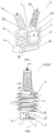
- the double-pole voltage transformer 1 comprises a tight enclosure 2 made as a resin cast with a central element 2a, a base 2b and side elements of the cast 2c.
- the element 2a has the form of a circular cylinder situated horizontally on the base 2b.
- the base 2b has the form of a cuboid with rounded edges.
- a cuboidal side element 2d integrated with the base 2b adjoins the base, more specifically one of its side walls.
- the element 2a of the transformer 1 has a partition 3 in the shape of a segment of a round shed adjoining the upper surface of the element 2a, in a plane perpendicular to the longitudinal axis of the element 2a, in the middle of its length "L" defined as the distance between the front surfaces of the cylinder of the central element 2a.
- a terminal box 4 is attached to a side wall of the element 2d of the enclosure 2. Inside the box 4, in a side wall of the element 2d there are located two complete terminals nn 5, 6 and an earthing terminal 7.
- the terminals 5 and 6 are galvanically connected inside the enclosure 2 with a low voltage winding nn 8.
- the winding nn 8 is wound on an insulating tube 9 fixed on a core 10 secured in a yoke 11 located in the enclosure 2.
- the earthing terminal 7 is galvanically connected inside the enclosure 2 with the yoke 11 and the core 10.
- assembly elements 13 in the form of threaded conducting inserts which are used to fix the transformer 1 to a support structure in the form of a plate or rails, not shown in the drawing.
- the elements 13 are galvanically connected inside the enclosure 2 with the earthing terminal 7.
- the sheds 14, 15, 16 are situated parallel to one another and on planes parallel to the bottom surface 12 of the base 2b of the transformer 1, with a fixed inter-shed spacing S, angle of inclination of the sheds ⁇ and an alternating overhang P1, P2, with P1>P2.
- projections 17a and 17b which are integrated with the central element 2a and which have the form of truncated cones.
- the projections 17a and 17b are situated symmetrically relative to the partition 3.
- Complete HV terminals 18a and 18b, fitted with threaded holes 19a and 19b respectively, are situated in the projections 17a and 17b.
- the terminal 18a is galvanically connected inside the enclosure 2 with the beginning of an HV winding
- the terminal 18b is galvanically connected inside the enclosure 2 with the end of the HV winding 20.
- the HV winding 20 is concentrically wound on a carcass 21.
- the carcass 21 is fixed on the core 10 concentrically and externally to the insulation tube 9.
- Bushings WN 22a and 22b are detachably fixed on the projections 17a and 17b.
- the HV bushings 22a, 22b are made as resin casts fitted with circumferential bushing sheds 23.
- cavities 24a, 24b respectively having the shapes of truncated cones situated coaxially to the longitudinal axis of the bushings 22a, 22b, and their shape corresponds to the shape of the projections 17a, 17b.
- conductive rods 25a, 25b respectively whose ends protrude outside the resin casts of the bushings 22a, 22b and they form first connections 26a, 26b and second connections 27a, 27b respectively.
- the connections 26a, 26b, 27a and 27b have threads, not shown in the drawing.
- the bushings 22a and 22b are fixed on the projections 17a and 17b respectively, by screwing the connections 27a, 27b located in the cavities 24a, 24b into the terminals 18a and 18b.
- the projections 17a, 17b fill the cavities 24a, 24b respectively, and the surfaces of contact between the external walls of the projections 17a, 17b respectively, and the surfaces of the cavities 24a, 24b are sealed with an insulating and sealing compound 28.
- the longitudinal axes of the bushings 22a, 22b are divergent to each other and they coincide with the longitudinal axes of the projections 17a and 17b respectively and they deviate from a vertical line symmetrically with respect to the partition 3 in a plane parallel to the planes of the walls of the base 2b by an angle ⁇ situated in a plane perpendicular to the bottom surface 12 of the base 2b.
- Sockets 29 for a mounting bracket are located on the side walls of the base 2b below the front surfaces of the element 2a screened by the circumferential sheds 14.
- the sockets 29 have the shape of semicircular longitudinal hollows.
- the diameter of the sockets 29 is selected to correspond to the diameter of the tubes of the mounting bracket, not shown in the drawing.
- the mounting bracket has a plate to which four arms in the form of tubes are attached. The mounting bracket makes it possible to turn the transformer 1 in a plane perpendicular to the longitudinal axis of the sockets 29, in order to set the transformer up in such way that the projections 17a, 17b point downwards.
- Such position of the transformer is necessary for a proper distribution of the sealing compound 28 when the connections 27a and 27b are screwed onto the terminals 18a and 18b respectively, so that the compound 28 does not overflow from the cavities 18a and 18b but is evenly distributed on the contact surfaces of the cavities 24a, 24b and of the projections 17a and 17b respectively.
Landscapes
- Engineering & Computer Science (AREA)
- Power Engineering (AREA)
- Housings And Mounting Of Transformers (AREA)
- Transformers For Measuring Instruments (AREA)
- Insulators (AREA)
- Power Conversion In General (AREA)
Applications Claiming Priority (2)
| Application Number | Priority Date | Filing Date | Title |
|---|---|---|---|
| PL124310U PL69613Y1 (pl) | 2015-08-10 | 2015-08-10 | Dwubiegunowy przekładnik napięciowy |
| PCT/PL2016/000065 WO2017026905A1 (en) | 2015-08-10 | 2016-06-24 | Double -pole voltage transformer |
Publications (2)
| Publication Number | Publication Date |
|---|---|
| EP3335229A1 EP3335229A1 (en) | 2018-06-20 |
| EP3335229B1 true EP3335229B1 (en) | 2020-01-08 |
Family
ID=57979435
Family Applications (1)
| Application Number | Title | Priority Date | Filing Date |
|---|---|---|---|
| EP16744575.8A Active EP3335229B1 (en) | 2015-08-10 | 2016-06-24 | Double-pole voltage transformer |
Country Status (5)
| Country | Link |
|---|---|
| US (1) | US11270830B2 (pl) |
| EP (1) | EP3335229B1 (pl) |
| CN (1) | CN107851502B (pl) |
| PL (1) | PL69613Y1 (pl) |
| WO (1) | WO2017026905A1 (pl) |
Family Cites Families (11)
| Publication number | Priority date | Publication date | Assignee | Title |
|---|---|---|---|---|
| US7808360B1 (en) * | 2004-12-20 | 2010-10-05 | Abb Technology Ag | Cushioning materials and method for applying the same to resin cast transformers |
| CN201489990U (zh) | 2009-09-01 | 2010-05-26 | 大连泰克电气有限公司 | Jdz12-10rw型户外电压互感器 |
| CN103748643A (zh) * | 2011-04-14 | 2014-04-23 | Abb技术有限公司 | 用于互感器的静电屏蔽 |
| CN202134390U (zh) | 2011-07-08 | 2012-02-01 | 大连北方互感器集团有限公司 | 铁路牵引变电所用电压互感器 |
| CN202205569U (zh) | 2011-09-07 | 2012-04-25 | 大连华夏泰克电气集团有限公司 | 一种电压互感器 |
| CN202534494U (zh) * | 2012-03-30 | 2012-11-14 | 大连北方互感器集团有限公司 | 户外带熔断器电压互感器 |
| CN202585086U (zh) * | 2012-05-29 | 2012-12-05 | 大连金业电力设备有限公司 | 10kV环氧树脂浇注复合型带熔断器保护电压互感器 |
| CN202633015U (zh) * | 2012-07-04 | 2012-12-26 | 大连金业电力设备有限公司 | 环氧树脂浇注复合型电压互感器 |
| CN203118750U (zh) * | 2013-01-14 | 2013-08-07 | 深圳市第二互感器科技有限公司 | 一种电压互感器 |
| CN203733605U (zh) | 2013-12-19 | 2014-07-23 | 安徽互感器有限公司 | 一种单相户外干式电压互感器 |
| CN203931778U (zh) * | 2014-05-07 | 2014-11-05 | 大连中广互感器制造有限公司 | 一种户外复合绝缘式电压互感器 |
-
2015
- 2015-08-10 PL PL124310U patent/PL69613Y1/pl unknown
-
2016
- 2016-06-24 EP EP16744575.8A patent/EP3335229B1/en active Active
- 2016-06-24 CN CN201680047152.4A patent/CN107851502B/zh active Active
- 2016-06-24 WO PCT/PL2016/000065 patent/WO2017026905A1/en not_active Ceased
-
2018
- 2018-02-08 US US15/891,880 patent/US11270830B2/en active Active
Non-Patent Citations (1)
| Title |
|---|
| None * |
Also Published As
| Publication number | Publication date |
|---|---|
| PL124310U1 (pl) | 2017-02-13 |
| CN107851502A (zh) | 2018-03-27 |
| US11270830B2 (en) | 2022-03-08 |
| EP3335229A1 (en) | 2018-06-20 |
| PL69613Y1 (pl) | 2017-12-29 |
| WO2017026905A8 (en) | 2018-02-08 |
| WO2017026905A1 (en) | 2017-02-16 |
| CN107851502B (zh) | 2019-05-07 |
| US20180158589A1 (en) | 2018-06-07 |
Similar Documents
| Publication | Publication Date | Title |
|---|---|---|
| WO2016188442A1 (zh) | 电机绝缘骨架及具有其的电机 | |
| US4523171A (en) | Dry-type transformer with windings cast in casting resin | |
| US11532432B2 (en) | Choke with busbar winding turns | |
| KR102103567B1 (ko) | 코일 장치 | |
| CN204696817U (zh) | 电机绝缘骨架及具有其的电机 | |
| RU2016106629A (ru) | Электрическая машина | |
| EP2417612B1 (en) | Multirange current instrument transformer for high voltage application | |
| EP3335229B1 (en) | Double-pole voltage transformer | |
| KR100867100B1 (ko) | 코일용 코어커버 | |
| ES2784365T3 (es) | Transformador encapsulado de tipo seco con terminal de conexión flexible | |
| RU2013126265A (ru) | Мультикамерный изолятор-разрядник и способ его изготовления | |
| KR101444813B1 (ko) | 일체형 실리콘 부스바의 제조를 위한 사출금형 | |
| EP3335230B1 (en) | Single-pole voltage transformer | |
| JP6452506B2 (ja) | コイル部品 | |
| RU2479059C1 (ru) | Трансформатор трехфазный высоковольтный с системой жидкостного охлаждения | |
| CN108028525B (zh) | 直流高压绝缘体和所属的制造方法 | |
| BR102014015636B1 (pt) | método de montagem de um transformador/reator, kit de peças para utilização na montagem de um transformador/reator e transformador/reator | |
| WO2024029319A1 (ja) | 端子台 | |
| RU181143U1 (ru) | Высоковольтный трехфазный трансформатор с системой жидкостного охлаждения | |
| JP2014222704A (ja) | コイル | |
| CN113488321A (zh) | 干式变压器及其绕制方法 | |
| ES2781834T3 (es) | Transformador de corriente que tiene varilla conductora de múltiples vueltas | |
| US1457784A (en) | Transformer | |
| CN107924759B (zh) | 测量用变换器的有源件单元和测量用变换器 | |
| US1659548A (en) | Transformer |
Legal Events
| Date | Code | Title | Description |
|---|---|---|---|
| STAA | Information on the status of an ep patent application or granted ep patent |
Free format text: STATUS: THE INTERNATIONAL PUBLICATION HAS BEEN MADE |
|
| PUAI | Public reference made under article 153(3) epc to a published international application that has entered the european phase |
Free format text: ORIGINAL CODE: 0009012 |
|
| STAA | Information on the status of an ep patent application or granted ep patent |
Free format text: STATUS: REQUEST FOR EXAMINATION WAS MADE |
|
| 17P | Request for examination filed |
Effective date: 20180130 |
|
| AK | Designated contracting states |
Kind code of ref document: A1 Designated state(s): AL AT BE BG CH CY CZ DE DK EE ES FI FR GB GR HR HU IE IS IT LI LT LU LV MC MK MT NL NO PL PT RO RS SE SI SK SM TR |
|
| AX | Request for extension of the european patent |
Extension state: BA ME |
|
| DAV | Request for validation of the european patent (deleted) | ||
| DAX | Request for extension of the european patent (deleted) | ||
| GRAP | Despatch of communication of intention to grant a patent |
Free format text: ORIGINAL CODE: EPIDOSNIGR1 |
|
| STAA | Information on the status of an ep patent application or granted ep patent |
Free format text: STATUS: GRANT OF PATENT IS INTENDED |
|
| INTG | Intention to grant announced |
Effective date: 20190402 |
|
| GRAS | Grant fee paid |
Free format text: ORIGINAL CODE: EPIDOSNIGR3 |
|
| GRAA | (expected) grant |
Free format text: ORIGINAL CODE: 0009210 |
|
| STAA | Information on the status of an ep patent application or granted ep patent |
Free format text: STATUS: THE PATENT HAS BEEN GRANTED |
|
| AK | Designated contracting states |
Kind code of ref document: B1 Designated state(s): AL AT BE BG CH CY CZ DE DK EE ES FI FR GB GR HR HU IE IS IT LI LT LU LV MC MK MT NL NO PL PT RO RS SE SI SK SM TR |
|
| REG | Reference to a national code |
Ref country code: GB Ref legal event code: FG4D |
|
| REG | Reference to a national code |
Ref country code: CH Ref legal event code: EP |
|
| REG | Reference to a national code |
Ref country code: DE Ref legal event code: R096 Ref document number: 602016027853 Country of ref document: DE |
|
| REG | Reference to a national code |
Ref country code: IE Ref legal event code: FG4D |
|
| REG | Reference to a national code |
Ref country code: AT Ref legal event code: REF Ref document number: 1223708 Country of ref document: AT Kind code of ref document: T Effective date: 20200215 |
|
| REG | Reference to a national code |
Ref country code: NL Ref legal event code: MP Effective date: 20200108 |
|
| REG | Reference to a national code |
Ref country code: LT Ref legal event code: MG4D |
|
| PG25 | Lapsed in a contracting state [announced via postgrant information from national office to epo] |
Ref country code: RS Free format text: LAPSE BECAUSE OF FAILURE TO SUBMIT A TRANSLATION OF THE DESCRIPTION OR TO PAY THE FEE WITHIN THE PRESCRIBED TIME-LIMIT Effective date: 20200108 Ref country code: LT Free format text: LAPSE BECAUSE OF FAILURE TO SUBMIT A TRANSLATION OF THE DESCRIPTION OR TO PAY THE FEE WITHIN THE PRESCRIBED TIME-LIMIT Effective date: 20200108 Ref country code: NL Free format text: LAPSE BECAUSE OF FAILURE TO SUBMIT A TRANSLATION OF THE DESCRIPTION OR TO PAY THE FEE WITHIN THE PRESCRIBED TIME-LIMIT Effective date: 20200108 Ref country code: PT Free format text: LAPSE BECAUSE OF FAILURE TO SUBMIT A TRANSLATION OF THE DESCRIPTION OR TO PAY THE FEE WITHIN THE PRESCRIBED TIME-LIMIT Effective date: 20200531 Ref country code: NO Free format text: LAPSE BECAUSE OF FAILURE TO SUBMIT A TRANSLATION OF THE DESCRIPTION OR TO PAY THE FEE WITHIN THE PRESCRIBED TIME-LIMIT Effective date: 20200408 Ref country code: FI Free format text: LAPSE BECAUSE OF FAILURE TO SUBMIT A TRANSLATION OF THE DESCRIPTION OR TO PAY THE FEE WITHIN THE PRESCRIBED TIME-LIMIT Effective date: 20200108 |
|
| PG25 | Lapsed in a contracting state [announced via postgrant information from national office to epo] |
Ref country code: HR Free format text: LAPSE BECAUSE OF FAILURE TO SUBMIT A TRANSLATION OF THE DESCRIPTION OR TO PAY THE FEE WITHIN THE PRESCRIBED TIME-LIMIT Effective date: 20200108 Ref country code: IS Free format text: LAPSE BECAUSE OF FAILURE TO SUBMIT A TRANSLATION OF THE DESCRIPTION OR TO PAY THE FEE WITHIN THE PRESCRIBED TIME-LIMIT Effective date: 20200508 Ref country code: BG Free format text: LAPSE BECAUSE OF FAILURE TO SUBMIT A TRANSLATION OF THE DESCRIPTION OR TO PAY THE FEE WITHIN THE PRESCRIBED TIME-LIMIT Effective date: 20200408 Ref country code: GR Free format text: LAPSE BECAUSE OF FAILURE TO SUBMIT A TRANSLATION OF THE DESCRIPTION OR TO PAY THE FEE WITHIN THE PRESCRIBED TIME-LIMIT Effective date: 20200409 Ref country code: LV Free format text: LAPSE BECAUSE OF FAILURE TO SUBMIT A TRANSLATION OF THE DESCRIPTION OR TO PAY THE FEE WITHIN THE PRESCRIBED TIME-LIMIT Effective date: 20200108 Ref country code: SE Free format text: LAPSE BECAUSE OF FAILURE TO SUBMIT A TRANSLATION OF THE DESCRIPTION OR TO PAY THE FEE WITHIN THE PRESCRIBED TIME-LIMIT Effective date: 20200108 |
|
| REG | Reference to a national code |
Ref country code: DE Ref legal event code: R097 Ref document number: 602016027853 Country of ref document: DE |
|
| PG25 | Lapsed in a contracting state [announced via postgrant information from national office to epo] |
Ref country code: RO Free format text: LAPSE BECAUSE OF FAILURE TO SUBMIT A TRANSLATION OF THE DESCRIPTION OR TO PAY THE FEE WITHIN THE PRESCRIBED TIME-LIMIT Effective date: 20200108 Ref country code: SK Free format text: LAPSE BECAUSE OF FAILURE TO SUBMIT A TRANSLATION OF THE DESCRIPTION OR TO PAY THE FEE WITHIN THE PRESCRIBED TIME-LIMIT Effective date: 20200108 Ref country code: EE Free format text: LAPSE BECAUSE OF FAILURE TO SUBMIT A TRANSLATION OF THE DESCRIPTION OR TO PAY THE FEE WITHIN THE PRESCRIBED TIME-LIMIT Effective date: 20200108 Ref country code: SM Free format text: LAPSE BECAUSE OF FAILURE TO SUBMIT A TRANSLATION OF THE DESCRIPTION OR TO PAY THE FEE WITHIN THE PRESCRIBED TIME-LIMIT Effective date: 20200108 Ref country code: DK Free format text: LAPSE BECAUSE OF FAILURE TO SUBMIT A TRANSLATION OF THE DESCRIPTION OR TO PAY THE FEE WITHIN THE PRESCRIBED TIME-LIMIT Effective date: 20200108 Ref country code: ES Free format text: LAPSE BECAUSE OF FAILURE TO SUBMIT A TRANSLATION OF THE DESCRIPTION OR TO PAY THE FEE WITHIN THE PRESCRIBED TIME-LIMIT Effective date: 20200108 |
|
| PLBE | No opposition filed within time limit |
Free format text: ORIGINAL CODE: 0009261 |
|
| STAA | Information on the status of an ep patent application or granted ep patent |
Free format text: STATUS: NO OPPOSITION FILED WITHIN TIME LIMIT |
|
| REG | Reference to a national code |
Ref country code: AT Ref legal event code: MK05 Ref document number: 1223708 Country of ref document: AT Kind code of ref document: T Effective date: 20200108 |
|
| 26N | No opposition filed |
Effective date: 20201009 |
|
| PG25 | Lapsed in a contracting state [announced via postgrant information from national office to epo] |
Ref country code: AT Free format text: LAPSE BECAUSE OF FAILURE TO SUBMIT A TRANSLATION OF THE DESCRIPTION OR TO PAY THE FEE WITHIN THE PRESCRIBED TIME-LIMIT Effective date: 20200108 Ref country code: MC Free format text: LAPSE BECAUSE OF FAILURE TO SUBMIT A TRANSLATION OF THE DESCRIPTION OR TO PAY THE FEE WITHIN THE PRESCRIBED TIME-LIMIT Effective date: 20200108 |
|
| REG | Reference to a national code |
Ref country code: CH Ref legal event code: PL |
|
| PG25 | Lapsed in a contracting state [announced via postgrant information from national office to epo] |
Ref country code: PL Free format text: LAPSE BECAUSE OF FAILURE TO SUBMIT A TRANSLATION OF THE DESCRIPTION OR TO PAY THE FEE WITHIN THE PRESCRIBED TIME-LIMIT Effective date: 20200108 Ref country code: SI Free format text: LAPSE BECAUSE OF FAILURE TO SUBMIT A TRANSLATION OF THE DESCRIPTION OR TO PAY THE FEE WITHIN THE PRESCRIBED TIME-LIMIT Effective date: 20200108 |
|
| GBPC | Gb: european patent ceased through non-payment of renewal fee |
Effective date: 20200624 |
|
| PG25 | Lapsed in a contracting state [announced via postgrant information from national office to epo] |
Ref country code: LU Free format text: LAPSE BECAUSE OF NON-PAYMENT OF DUE FEES Effective date: 20200624 |
|
| REG | Reference to a national code |
Ref country code: BE Ref legal event code: MM Effective date: 20200630 |
|
| PG25 | Lapsed in a contracting state [announced via postgrant information from national office to epo] |
Ref country code: IE Free format text: LAPSE BECAUSE OF NON-PAYMENT OF DUE FEES Effective date: 20200624 Ref country code: GB Free format text: LAPSE BECAUSE OF NON-PAYMENT OF DUE FEES Effective date: 20200624 Ref country code: FR Free format text: LAPSE BECAUSE OF NON-PAYMENT OF DUE FEES Effective date: 20200630 Ref country code: CH Free format text: LAPSE BECAUSE OF NON-PAYMENT OF DUE FEES Effective date: 20200630 Ref country code: LI Free format text: LAPSE BECAUSE OF NON-PAYMENT OF DUE FEES Effective date: 20200630 |
|
| PG25 | Lapsed in a contracting state [announced via postgrant information from national office to epo] |
Ref country code: BE Free format text: LAPSE BECAUSE OF NON-PAYMENT OF DUE FEES Effective date: 20200630 |
|
| PG25 | Lapsed in a contracting state [announced via postgrant information from national office to epo] |
Ref country code: TR Free format text: LAPSE BECAUSE OF FAILURE TO SUBMIT A TRANSLATION OF THE DESCRIPTION OR TO PAY THE FEE WITHIN THE PRESCRIBED TIME-LIMIT Effective date: 20200108 Ref country code: MT Free format text: LAPSE BECAUSE OF FAILURE TO SUBMIT A TRANSLATION OF THE DESCRIPTION OR TO PAY THE FEE WITHIN THE PRESCRIBED TIME-LIMIT Effective date: 20200108 Ref country code: CY Free format text: LAPSE BECAUSE OF FAILURE TO SUBMIT A TRANSLATION OF THE DESCRIPTION OR TO PAY THE FEE WITHIN THE PRESCRIBED TIME-LIMIT Effective date: 20200108 |
|
| PG25 | Lapsed in a contracting state [announced via postgrant information from national office to epo] |
Ref country code: MK Free format text: LAPSE BECAUSE OF FAILURE TO SUBMIT A TRANSLATION OF THE DESCRIPTION OR TO PAY THE FEE WITHIN THE PRESCRIBED TIME-LIMIT Effective date: 20200108 Ref country code: AL Free format text: LAPSE BECAUSE OF FAILURE TO SUBMIT A TRANSLATION OF THE DESCRIPTION OR TO PAY THE FEE WITHIN THE PRESCRIBED TIME-LIMIT Effective date: 20200108 |
|
| PGFP | Annual fee paid to national office [announced via postgrant information from national office to epo] |
Ref country code: DE Payment date: 20250618 Year of fee payment: 10 |
|
| PGFP | Annual fee paid to national office [announced via postgrant information from national office to epo] |
Ref country code: CZ Payment date: 20250617 Year of fee payment: 10 |
|
| PGFP | Annual fee paid to national office [announced via postgrant information from national office to epo] |
Ref country code: IT Payment date: 20250624 Year of fee payment: 10 |