EP3334945B1 - Verfahren zum setzen einer schraube - Google Patents
Verfahren zum setzen einer schraube Download PDFInfo
- Publication number
- EP3334945B1 EP3334945B1 EP16744728.3A EP16744728A EP3334945B1 EP 3334945 B1 EP3334945 B1 EP 3334945B1 EP 16744728 A EP16744728 A EP 16744728A EP 3334945 B1 EP3334945 B1 EP 3334945B1
- Authority
- EP
- European Patent Office
- Prior art keywords
- screw
- thread
- tap
- cutting
- external thread
- Prior art date
- Legal status (The legal status is an assumption and is not a legal conclusion. Google has not performed a legal analysis and makes no representation as to the accuracy of the status listed.)
- Active
Links
Images
Classifications
-
- F—MECHANICAL ENGINEERING; LIGHTING; HEATING; WEAPONS; BLASTING
- F16—ENGINEERING ELEMENTS AND UNITS; GENERAL MEASURES FOR PRODUCING AND MAINTAINING EFFECTIVE FUNCTIONING OF MACHINES OR INSTALLATIONS; THERMAL INSULATION IN GENERAL
- F16B—DEVICES FOR FASTENING OR SECURING CONSTRUCTIONAL ELEMENTS OR MACHINE PARTS TOGETHER, e.g. NAILS, BOLTS, CIRCLIPS, CLAMPS, CLIPS OR WEDGES; JOINTS OR JOINTING
- F16B25/00—Screws that cut thread in the body into which they are screwed, e.g. wood screws
- F16B25/001—Screws that cut thread in the body into which they are screwed, e.g. wood screws characterised by the material of the body into which the screw is screwed
- F16B25/0026—Screws that cut thread in the body into which they are screwed, e.g. wood screws characterised by the material of the body into which the screw is screwed the material being a hard non-organic material, e.g. stone, concrete or drywall
-
- B—PERFORMING OPERATIONS; TRANSPORTING
- B23—MACHINE TOOLS; METAL-WORKING NOT OTHERWISE PROVIDED FOR
- B23G—THREAD CUTTING; WORKING OF SCREWS, BOLT HEADS, OR NUTS, IN CONJUNCTION THEREWITH
- B23G1/00—Thread cutting; Automatic machines specially designed therefor
- B23G1/16—Thread cutting; Automatic machines specially designed therefor in holes of workpieces by taps
-
- B—PERFORMING OPERATIONS; TRANSPORTING
- B23—MACHINE TOOLS; METAL-WORKING NOT OTHERWISE PROVIDED FOR
- B23P—METAL-WORKING NOT OTHERWISE PROVIDED FOR; COMBINED OPERATIONS; UNIVERSAL MACHINE TOOLS
- B23P19/00—Machines for simply fitting together or separating metal parts or objects, or metal and non-metal parts, whether or not involving some deformation; Tools or devices therefor so far as not provided for in other classes
- B23P19/04—Machines for simply fitting together or separating metal parts or objects, or metal and non-metal parts, whether or not involving some deformation; Tools or devices therefor so far as not provided for in other classes for assembling or disassembling parts
- B23P19/048—Springs
-
- B—PERFORMING OPERATIONS; TRANSPORTING
- B23—MACHINE TOOLS; METAL-WORKING NOT OTHERWISE PROVIDED FOR
- B23P—METAL-WORKING NOT OTHERWISE PROVIDED FOR; COMBINED OPERATIONS; UNIVERSAL MACHINE TOOLS
- B23P19/00—Machines for simply fitting together or separating metal parts or objects, or metal and non-metal parts, whether or not involving some deformation; Tools or devices therefor so far as not provided for in other classes
- B23P19/04—Machines for simply fitting together or separating metal parts or objects, or metal and non-metal parts, whether or not involving some deformation; Tools or devices therefor so far as not provided for in other classes for assembling or disassembling parts
- B23P19/06—Screw or nut setting or loosening machines
-
- B—PERFORMING OPERATIONS; TRANSPORTING
- B28—WORKING CEMENT, CLAY, OR STONE
- B28D—WORKING STONE OR STONE-LIKE MATERIALS
- B28D1/00—Working stone or stone-like materials, e.g. brick, concrete or glass, not provided for elsewhere; Machines, devices, tools therefor
- B28D1/14—Working stone or stone-like materials, e.g. brick, concrete or glass, not provided for elsewhere; Machines, devices, tools therefor by boring or drilling
- B28D1/146—Tools therefor
-
- B—PERFORMING OPERATIONS; TRANSPORTING
- B28—WORKING CEMENT, CLAY, OR STONE
- B28D—WORKING STONE OR STONE-LIKE MATERIALS
- B28D1/00—Working stone or stone-like materials, e.g. brick, concrete or glass, not provided for elsewhere; Machines, devices, tools therefor
- B28D1/18—Working stone or stone-like materials, e.g. brick, concrete or glass, not provided for elsewhere; Machines, devices, tools therefor by milling, e.g. channelling by means of milling tools
- B28D1/186—Tools therefor, e.g. having exchangeable cutter bits
-
- F—MECHANICAL ENGINEERING; LIGHTING; HEATING; WEAPONS; BLASTING
- F16—ENGINEERING ELEMENTS AND UNITS; GENERAL MEASURES FOR PRODUCING AND MAINTAINING EFFECTIVE FUNCTIONING OF MACHINES OR INSTALLATIONS; THERMAL INSULATION IN GENERAL
- F16B—DEVICES FOR FASTENING OR SECURING CONSTRUCTIONAL ELEMENTS OR MACHINE PARTS TOGETHER, e.g. NAILS, BOLTS, CIRCLIPS, CLAMPS, CLIPS OR WEDGES; JOINTS OR JOINTING
- F16B25/00—Screws that cut thread in the body into which they are screwed, e.g. wood screws
- F16B25/0036—Screws that cut thread in the body into which they are screwed, e.g. wood screws characterised by geometric details of the screw
- F16B25/0042—Screws that cut thread in the body into which they are screwed, e.g. wood screws characterised by geometric details of the screw characterised by the geometry of the thread, the thread being a ridge wrapped around the shaft of the screw
- F16B25/0047—Screws that cut thread in the body into which they are screwed, e.g. wood screws characterised by geometric details of the screw characterised by the geometry of the thread, the thread being a ridge wrapped around the shaft of the screw the ridge being characterised by its cross-section in the plane of the shaft axis
-
- F—MECHANICAL ENGINEERING; LIGHTING; HEATING; WEAPONS; BLASTING
- F16—ENGINEERING ELEMENTS AND UNITS; GENERAL MEASURES FOR PRODUCING AND MAINTAINING EFFECTIVE FUNCTIONING OF MACHINES OR INSTALLATIONS; THERMAL INSULATION IN GENERAL
- F16B—DEVICES FOR FASTENING OR SECURING CONSTRUCTIONAL ELEMENTS OR MACHINE PARTS TOGETHER, e.g. NAILS, BOLTS, CIRCLIPS, CLAMPS, CLIPS OR WEDGES; JOINTS OR JOINTING
- F16B25/00—Screws that cut thread in the body into which they are screwed, e.g. wood screws
- F16B25/0036—Screws that cut thread in the body into which they are screwed, e.g. wood screws characterised by geometric details of the screw
- F16B25/0042—Screws that cut thread in the body into which they are screwed, e.g. wood screws characterised by geometric details of the screw characterised by the geometry of the thread, the thread being a ridge wrapped around the shaft of the screw
- F16B25/0073—Screws that cut thread in the body into which they are screwed, e.g. wood screws characterised by geometric details of the screw characterised by the geometry of the thread, the thread being a ridge wrapped around the shaft of the screw characterised by its pitch, e.g. a varying pitch
-
- B—PERFORMING OPERATIONS; TRANSPORTING
- B23—MACHINE TOOLS; METAL-WORKING NOT OTHERWISE PROVIDED FOR
- B23G—THREAD CUTTING; WORKING OF SCREWS, BOLT HEADS, OR NUTS, IN CONJUNCTION THEREWITH
- B23G2200/00—Details of threading tools
- B23G2200/46—Tools having a section of polygonal form, e.g. for the transmission of torque
-
- B—PERFORMING OPERATIONS; TRANSPORTING
- B23—MACHINE TOOLS; METAL-WORKING NOT OTHERWISE PROVIDED FOR
- B23G—THREAD CUTTING; WORKING OF SCREWS, BOLT HEADS, OR NUTS, IN CONJUNCTION THEREWITH
- B23G2210/00—Details of threads produced
- B23G2210/04—Internal threads
-
- B—PERFORMING OPERATIONS; TRANSPORTING
- B23—MACHINE TOOLS; METAL-WORKING NOT OTHERWISE PROVIDED FOR
- B23G—THREAD CUTTING; WORKING OF SCREWS, BOLT HEADS, OR NUTS, IN CONJUNCTION THEREWITH
- B23G2225/00—Materials of threading tools, workpieces or other structural elements
Definitions
- the invention further relates to a container containing articles for carrying out such a method.
- the DE 19905845 A1 describes a screw mounting kit for concrete in which a screw and a screw designed in the manner of a screw tap are provided, wherein the core diameter of the tap is smaller than the core diameter of the screw, so that the game at the core of the screw is smaller than that Play at the core of the tap.
- the core diameter of the tap is smaller than the core diameter of the screw, so that the game at the core of the screw is smaller than that Play at the core of the tap.
- the screw is housed with a fixed seat in the pre-cut thread.
- the outer diameter of the screw in the region of the cylindrical thread should be smaller than the outer diameter of the tap, which is to be achieved so that when screwing the screw into the thread no clamping on the outer circumference of the thread of the screw occur.
- the US 4439077 A describes a concrete screw that is designed so that drilling dust is compacted when screwing. Another concrete screw is out of the US 4842467A known.
- US 8696477 A . US 8182185 A . US 7740435 A . US 8182186 A and US 7484920 A disclose concrete screws, which have cutting bodies in the thread path, which have a relation to the remaining thread increased hardness. This makes it possible to use a material with a comparatively high corrosion resistance for the remaining screw areas, even if this should have a comparatively low hardness.
- the object of the invention is to provide a method for setting a screw in a borehole in a substrate made of a mineral building material, in particular concrete, with which a particularly reliable setting of the screw is possible with little effort, and with the particularly good load values and a Particularly good corrosion resistance can be achieved, and to provide a container containing articles for performing such a method.
- An inventive method is characterized in that the outer diameter of the cutting thread of the tap is smaller than the outer diameter of the external thread of the screw.
- a basic idea of the invention can be seen in the use of the tap to cut an internal thread in the borehole, into which the external thread of the screw is subsequently screwed, wherein the cutting thread of the tap is dimensioned so that the pre-cut internal thread relative to the external thread of the screw has a lesser degree.
- the invention comes in and provides, according to a first idea of the invention, to pre-cut in the concrete substrate by means of a tap a preliminary thread, namely the external thread.
- a preliminary thread namely the external thread.
- the pre-thread has a reduced mass relative to the external thread of the screw, that is to say the thread produced with the tap is smaller in its external diameter than the external screw diameter.
- the thread crest of the external thread of the screw cuts into the substrate when the screw is screwed in, so that loosely formed substrate particles are produced when the screw is screwed in.
- These substrate particles can provide for an advantageous compression of the screw with the surrounding borehole wall, which stabilizes the borehole and therefore can provide particularly good load values. According to the invention, particularly high load values can thus be obtained with particularly high reliability.
- the cutting thread of the tap and / or the external thread of the screw are preferably cylindrical thread.
- the outer diameter of the cutting thread of the tap is preferably constant over at least 50%, preferably over at least 75% or 80%, of the thread length of the cutting thread of the tap.
- the outside diameter of the external thread of the screw is preferably constant over at least 50%, preferably over at least 75% or 80%, of the thread length of the external thread of the screw.
- the substrate of a mineral building material may in particular be a concrete substrate.
- the tap preferably has a shaft on which the cutting thread is arranged.
- the screw also preferably has a shaft on which the external thread is arranged.
- time between the generation of the internal thread in the borehole and the subsequent screwing the screw one or more intermediate steps, such as cleaning steps, can be provided.
- these intermediate steps leave the structure of the substrate, in particular the structure of the internal thread produced by the tap, at least approximately unchanged.
- the tap may preferably machine the substrate to produce the external thread.
- the cutting thread of the tap and the external thread of the screw are in particular gleichsinning.
- the outer diameter of the cutting thread of the tap is 0.85 times to 0.92 times the outer diameter of the external thread of the screw.
- a further advantageous embodiment is that the thread pitch of the cutting thread of the tap by less than 3%, preferably less than 1%, deviates from the thread pitch of the external thread of the screw. This can further improve reliability and performance.
- the core diameter of the cutting thread of the tap deviates by less than 3%, preferably less than 1%, from the core diameter of the external thread of the screw. As a result, the reliability can be further increased and in particular an undesired damage to the borehole can be counteracted.
- the thread length of the cutting thread of the tap deviates by less than 3%, preferably less than 1%, from the thread length of the external thread of the screw.
- the reliability can be further increased, since this can be ensured in a particularly simple manner that the Vorgewinde has the correct depth.
- an attachment to the substrate is set when screwing the screw, preferably by the screw is introduced through a recess in the attachment through into the wellbore.
- the attachment is set at the first screwing in the screw at the same time.
- the attachment can be positively secured to the substrate, for example by a screw head provided in the rear region of the screw.
- the drive may, for example, be a screw head, that is to say in particular a locally enlarged cross section of the screw.
- the screw head can have an outer polygon or a polygon socket.
- the drive can also be a simple polygon socket.
- It may be a container containing a screw and / or a tap, and further comprising an instruction manual, which teaches a method according to the invention using the screw or the tap, may be provided.
- the container thus contains an instruction manual which teaches the method steps according to the invention, as well as at least one of the items required for carrying out the method.
- the teaching for carrying out the method according to the invention can be written down in the instructions for use. Under a container can be understood in the usual way in particular the entirety of packaging and the packaged goods.
- the invention also relates to a container containing the essential objects for carrying out the method, that is containing a screw for screwing into a borehole in a substrate of a mineral building material, wherein the screw in a front region an external thread and in a rear region a drive for Introducing a torque in the screw, and provided with a cutting screw tap, wherein the outer diameter of the cutting thread of the tap is smaller than the outer diameter of the external thread of the screw.
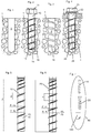
- FIGS. 1 to 4 show different stages in the implementation of a method according to the invention.
- a tap 10 is introduced into the borehole 2.
- the tap 10 has a preferably at least approximately cylindrical shaft 15 and a helical cutting thread 16, which is arranged on the shaft 15.
- the tap 10 has a drive 11 exemplified as a head, in particular hexagonal head, for introducing a torque into the shaft 15.
- the cutting thread 16 has an outer diameter ⁇ da s (see FIG. 5 Therefore, when screwing the tap 10 into the borehole 2, the cutting thread 16 cuts into the substrate 1 surrounding the borehole 2 and creates an internal thread 19 in the borehole 2.
- the core diameter ⁇ dk s of the cutting thread 16 of the tap 10 preferably be smaller than the inner diameter of the borehole 2.
- the screw 20 has a preferably at least approximately cylindrical shaft 25 and a helical external thread 26, which is arranged on the shaft 25.
- the screw 20 has a drive 21, which is shown as a head, in particular a hexagon head, for introducing a torque into the shaft 25 and for holding the attachment 9 in a form-locking manner.
- the external thread 26 of the screw 20 has an outer diameter ⁇ da (cf. FIG. 6 ), which is larger than the outer diameter ⁇ da s of the cutting thread 16, and which is thus greater than the outer diameter of the inner thread 19 produced by the cutting thread 16 in the borehole 2.
- the internal thread 19 is slightly expanded radially when screwing the screw 20.
- 2 loose substrate particles fall down in the borehole, which can provide for a compression of the shank 25 of the screw and thus a radial support of the borehole 2, whereby particularly good load values for the screw 20 can be obtained.
- the core diameter ⁇ dk of the external thread 26 of the screw 20 preferably be smaller than the inner diameter of the borehole 2.
- FIG. 7 shows a schematic view of a container according to the invention 90, which includes a screw 20, a tap 10 and an instruction manual 100, wherein in the instructions for use 100 a method according to the invention is described.
Landscapes
- Engineering & Computer Science (AREA)
- Mechanical Engineering (AREA)
- General Engineering & Computer Science (AREA)
- Physics & Mathematics (AREA)
- Geometry (AREA)
- Mining & Mineral Resources (AREA)
- Processing Of Stones Or Stones Resemblance Materials (AREA)
- Joining Of Building Structures In Genera (AREA)
Description
- Die Erfindung betrifft ein Verfahren zum Setzen einer Schraube, welche in einem vorderen Bereich ein Aussengewinde und in einem rückwärtigen Bereich einen Antrieb zum Einleiten eines Drehmoments in die Schraube aufweist, in einem Bohrloch in einem Substrat aus einem mineralischen Baustoff, gemäss dem Oberbegriff des Anspruchs 1. Bei einem solchen Verfahren ist vorgesehen, dass
- mittels eines mit einem Schneidgewinde versehenen Gewindebohrers ein Innengewinde im Bohrloch erzeugt wird, und
- anschliessend die Schraube in das Bohrloch eingebracht, insbesondere eingedreht, wird und dabei das Aussengewinde der Schraube in das vom Gewindebohrer erzeugte Innengewinde im Bohrloch eingeschraubt wird.
- Die Erfindung betrifft ferner ein Gebinde enthaltend Gegenstände zur Durchführung eines solchen Verfahrens.
- Aus der
DE 19735280 A1 ist es bekannt, vor dem Einschrauben einer Betonschraube ein Gewinde vorzuschneiden, wodurch eine grössere Freiheit bei der Materialauswahl für die Betonschraube gegeben sein soll. - Die
DE 19905845 A1 beschreibt einen Schraub-Befestigungs-Satz für Beton, bei dem eine Schraube und ein nach Art einer Schraube ausgebildeter Gewindebohrer vorgesehen sind, wobei der Kerndurchmesser des Gewindebohrers kleiner ist als der Kerndurchmesser der Schraube, so dass das Spiel am Kern der Schraube kleiner ist als das Spiel am Kern des Gewindebohrers. Hierdurch soll erreicht werden, dass einerseits mit dem Gewindebohrer das beim Gewindeschneiden auftretende Schneidmehl nach aussen abtransportiert werden kann, und dass andererseits die Schraube mit festem Sitz in dem vorgeschnittenen Gewinde untergebracht wird. Vorzugsweise soll der Aussendurchmesser der Schraube im Bereich des zylindrischen Gewindes kleiner als der Aussendurchmesser des Gewindebohrers sein, wodurch erreicht werden soll, dass beim Einschrauben der Schraube in den Gewindegang keine Klemmungen am Aussenumfang des Gewindes der Schraube auftreten. - Aus der
EP 0625400A1 geht ein Werkzeug zum Erzeugen eines Innengewindes in Beton, Mauerwerk oder dergleichen hervor. - Die
US 4439077 A beschreibt eine Betonschraube, die so ausgelegt ist, dass beim Eindrehen Bohrmehl verdichtet wird. Eine weitere Betonschraube ist aus derUS 4842467A bekannt. - Die
US 8696477 A ,US 8182185 A ,US 7740435 A ,US 8182186 A undUS 7484920 A offenbaren Betonschrauben, welche im Gewindeverlauf Schneidkörper aufweisen, die eine gegenüber dem restlichen Gewinde erhöhte Härte aufweisen. Dies ermöglicht es, für die verbleibenden Schraubenbereiche ein Material mit einer vergleichsweise hohen Korrosionsbeständigkeit einzusetzen, selbst wenn dieses eine vergleichsweise geringe Härte haben sollte. - Aufgabe der Erfindung ist es, ein Verfahren zum Setzen einer Schraube in einem Bohrloch in einem Substrat aus einem mineralischen Baustoff, insbesondere Beton, anzugeben, mit dem bei geringem Aufwand ein besonders zuverlässiges Setzen der Schraube möglich ist, und mit dem besonders guten Lastwerten und eine besonders gute Korrosionsbeständigkeit erzielt werden können, sowie ein Gebinde enthaltend Gegenstände zur Durchführung eines solchen Verfahrens anzugeben.
- Die Aufgabe wird erfindungsgemäss durch ein Verfahren mit den Merkmalen des Anspruchs 1 und ein Gebinde mit den Merkmalen des Anspruchs 8 gelöst. Bevorzugte Ausführungsformen sind in den abhängigen Ansprüchen angegeben.
- Ein erfindungsgemässes Verfahren ist dadurch gekennzeichnet, dass der Aussendurchmesser des Schneidgewindes des Gewindebohrers kleiner ist als der Aussendurchmesser des Aussengewindes der Schraube.
- Ein Grundgedanke der Erfindung kann darin gesehen werden, mittels des Gewindebohrers ein Innengewinde im Bohrloch vorzuschneiden, in welches das Aussengewinde der Schraube anschliessend eingeschraubt wird, wobei das Schneidgewinde des Gewindebohrers so dimensioniert ist, dass das vorgeschnittene Innengewinde gegenüber dem Aussengewinde der Schraube ein Mindermass aufweist.
- Im Rahmen der Erfindung wurde beobachtet, dass es beim Setzen von Schrauben in mineralischen Werkstoffen, insbesondere auch in hoch- oder höchstfestem Beton und vor allem bei Armierungstreffern, zu einem unerwünschten Blocken der Schraube kommen kann. Dies wurde insbesondere auch bei Schrauben mit Schneidkörpern im Gewindeverlauf beobachtet, und kann auf eine unerwünschte Wechselwirkung der Oberflächen der Schneidkörper und/oder der Oberflächen der für die Schneidkörper vorgesehenen Gewindeaussparungen mit dem Substrat zurückzuführen sein. Darüber hinaus wurde in Rahmen der Erfindung beobachtet, dass es bei Armierungstreffern zu einem hohen Verschleiss oder im Extremfall gar zu einer vollständigen Zerstörung der Gewindewendel kommen kann, was zu Performanceverlusten oder im Extremfall zu einem Durchdrehen führen kann, wobei der Befestigungspunkt unbrauchbar werden kann. Hier setzt die Erfindung an und sieht gemäss einem ersten Erfindungsgrundgedanken vor, im Betonsubstrat mittels eines Gewindebohrers ein Vorgewinde, nämlich das Aussengewinde, vorzuschneiden. Hierdurch kann dem oben genannten Blocken und dem oben genannten unerwünschten erhöhten Verschleiss, insbesondere bei Armierungstreffern, einfach entgegengewirkt werden, so dass eine besonders hohe Zuverlässigkeit gegeben ist. Entsprechend einem zweiten Erfindungsgrundgedanken weist das Vorgewinde dabei ein Mindermass gegenüber dem Aussengewinde der Schraube auf, das heisst das mit dem Gewindebohrer erzeugte Gewinde ist in seinem Aussendurchmesser kleiner als der Schraubenaussendurchmesser. Aufgrund dieses Mindermasses schneidet die Gewindespitze des Aussengewindes der Schraube beim Einschrauben der Schraube in das Substrat ein, so dass beim Einschrauben der Schraube gezielt lose Substratpartikel erzeugt werden. Diese Substratpartikel wiederum können für eine vorteilhafte Verpressung der Schraube mit der umgebenden Bohrlochwand sorgen, was das Bohrloch stabilisiert und daher für besonders gute Lastwerte sorgen kann. Erfindungsgemäss können somit bei besonders hoher Zuverlässigkeit besonders hohe Lastwerte erhalten werden.
- Unter dem Aussendurchmesser eines Gewindes kann in üblicher Weise insbesondere der Durchmesser eines das Gewinde einhüllenden Zylinders verstanden werden. Das Schneidgewinde des Gewindebohrers und/oder das Aussengewinde der Schraube sind vorzugsweise Zylindergewinde. Bevorzugt ist der Aussendurchmesser des Schneidgewindes des Gewindebohrers über zumindest 50%, vorzugsweise über zumindest 75% oder 80%, der Gewindelänge des Schneidgewindes des Gewindebohrers konstant. Alternativ oder zusätzlich ist bevorzugt der Aussendurchmesser des Aussengewindes der Schraube über zumindest 50%, vorzugsweise über zumindest 75% oder 80%, der Gewindelänge des Aussengewindes der Schraube konstant.
- Das Substrat aus einem mineralischen Baustoff kann insbesondere ein Betonsubstrat sein. Der Gewindebohrer weist vorzugsweise einen Schaft auf, an dem das Schneidgewinde angeordnet ist. Auch die Schraube weist vorzugsweise einen Schaft auf, an dem das Aussengewinde angeordnet ist. Zeitlich zwischen dem Erzeugen des Innengewindes im Bohrloch und dem anschliessenden Einschrauben der Schraube können ein oder mehrere Zwischenschritte, wie Reinigungsschritte, vorgesehen werden. Vorzugsweise lassen diese Zwischenschritte die Struktur des Substrats, insbesondere die Struktur des vom Gewindebohrer erzeugten Innengewindes, zumindest annähernd unverändert. Der Gewindebohrer kann das Substrat zum Erzeugen des Aussengewindes vorzugsweise spanend bearbeiten.
- Das Schneidgewinde des Gewindebohrers und das Aussengewinde der Schraube sind insbesondere gleichsinning.
- Besonders bevorzugt ist es, dass der Aussendurchmesser des Schneidgewindes des Gewindebohrers das 0.85-fache bis 0.92-fache des Aussendurchmessers des Aussengewindes der Schraube beträgt. Experimente haben gezeigt, dass in diesem Bereich einerseits eine besonders gute Tragfähigkeit gegeben ist, da Substratpartikel, welche zum Verpressen im Bohrloch benötigt werden, in ausreichendem Maße zur Verfügung stehen, und dass andererseits ein besonders gutes Setzverhalten gegeben ist. Insbesondere lässt sich die Schraube zwar relativ leicht setzen, sie fällt aber nicht einfach in das Bohrloch hinein, das heisst es ist ein solides Setzgefühl gegeben.
- Eine weitere vorteilhafte Ausgestaltung liegt darin, dass die Gewindesteigung des Schneidgewindes des Gewindebohrers um weniger als 3%, vorzugsweise weniger als 1%, von der Gewindesteigung des Aussengewindes der Schraube abweicht. Hierdurch kann die Zuverlässigkeit und Leistungsfähigkeit noch weiter verbessert werden.
- Weiterhin ist es bevorzugt, dass der Kerndurchmesser des Schneidgewindes des Gewindebohrers um weniger als 3%, vorzugsweise weniger als 1%, vom Kerndurchmesser des Aussengewindes der Schraube abweicht. Hierdurch kann die Zuverlässigkeit noch weiter gesteigert werden und insbesondere einer unerwünschten Beschädigung des Bohrlochs entgegengewirkt werden.
- Insbesondere kann vorgesehen sein, dass die Gewindelänge des Schneidgewindes des Gewindebohrers um weniger als 3%, vorzugsweise weniger als 1%, von der Gewindelänge des Aussengewindes der Schraube abweicht. Auch hierdurch kann die Zuverlässigkeit noch weiter gesteigert werden, da hiermit in besonders einfacher Weise gewährleistet werden kann, dass das Vorgewinde die korrekte Tiefe hat.
- Zweckmässigerweise wird beim Einschrauben der Schraube zugleich ein Anbauteil am Substrat festgelegt, vorzugsweise indem die Schraube durch eine Ausnehmung im Anbauteil hindurch in das Bohrloch eingebracht wird. Somit wird also beim erstmaligen Einschrauben der Schraube zugleich das Anbauteil festgelegt. Hierdurch kann die Zuverlässigkeit noch weiter gesteigert werden, da in besonders einfacher Weise gewährleistet werden kann, dass beim Aufweiten des Vorgewindes anfallende Substratpartikel auch tatsächlich zur Verpressung und somit zur Tragfähigkeitserhöhung der Schraube beitragen. Vorzugsweise kann das Anbauteil formschlüssig am Substrat festgelegt werden, beispielsweise durch einen im rückwärtigen Bereich der Schraube vorgesehenen Schraubenkopf.
- Der Antrieb kann beispielsweise ein Schraubenkopf sein, das heisst insbesondere ein lokal querschnittsvergrösserter Bereich der Schraube. Der Schraubenkopf kann einen Aussenmehrkant oder einen Innenmehrkant aufweisen. Der Antrieb kann aber auch ein einfacher Innenmehrkant sein.
- Es kann ein Gebinde enthaltend eine Schraube und/oder einen Gewindebohrer, und enthaltend ferner eine Gebrauchsanweisung, welche ein erfindungsgemässes Verfahren unter Verwendung der Schraube beziehungsweise des Gewindebohrers lehrt, vorgesehen sein. Das Gebinde enthält somit eine Gebrauchsanweisung, welche die erfindungsgemässen Verfahrensschritte lehrt, sowie zumindest einen der für die Durchführung des Verfahrens erforderlichen Gegenstände. Insbesondere kann die Lehre zur Durchführung des erfindungsgemässen Verfahrens in der Gebrauchsanweisung niedergeschrieben sein. Unter einem Gebinde kann in fachüblicher Weise insbesondere die Gesamtheit aus Verpackung und der verpackten Ware verstanden werden.
- Die Erfindung betrifft auch ein Gebinde enthaltend die zur Durchführung des Verfahrens wesentlichen Gegenstände, das heisst enthaltend eine Schraube zum Einschrauben in ein Bohrloch in einem Substrat aus einem mineralischen Baustoff, wobei die Schraube in einem vorderen Bereich ein Aussengewinde und in einem rückwärtigen Bereich einen Antrieb zum Einleiten eines Drehmoments in die Schraube aufweist, und einen mit einem Schneidgewinde versehenen Gewindebohrer, wobei der Aussendurchmesser des Schneidgewindes des Gewindebohrers kleiner ist als der Aussendurchmesser des Aussengewindes der Schraube.
- Im Zusammenhang mit dem erfindungsgemässen Verfahren genannte Merkmale können auch bei den Gebinden zum Einsatz kommen, so wie umgekehrt im Zusammenhang mit den Gebinden genannte Merkmale auch beim erfindungsgemässen Verfahren zum Einsatz kommen können.
- Die Erfindung wird nachfolgend anhand bevorzugter Ausführungsbeispiele näher erläutert, die schematisch in den beiliegenden Figuren dargestellt sind, wobei einzelne Merkmale der nachfolgend gezeigten Ausführungsbeispiele im Rahmen der Erfindung grundsätzlich einzeln oder in beliebiger Kombination realisiert werden können. In den Figuren zeigen schematisch:
- Figuren 1 bis 4:
- schematische Darstellungen aufeinanderfolgender Stadien bei der Durchführung des erfindungsgemässen Verfahrens;
- Figur 5:
- eine Detailansicht des Gewindebohrers, welcher beim Verfahren gemäss
Figuren 1 bis 4 zum Einsatz kommt, mit Blickrichtung von der Seite; - Figur 6:
- eine Detailansicht der Schraube, welche beim Verfahren gemäss
Figuren 1 bis 4 zum Einsatz kommt, mit Blickrichtung von der Seite; und - Figur 7:
- eine schematische Ansicht eines erfindungsgemässen Gebindes.
- Die
Figuren 1 bis 4 zeigen unterschiedliche Stadien bei der Durchführung eines erfindungsgemässen Verfahrens. - Zunächst wird beim Verfahren, wie in
Figur 1 gezeigt, in einem Substrat 1 aus einem mineralischen Baustoff, insbesondere aus Beton, ein vorzugsweise zumindest annähernd zylindrisches Bohrloch 2 bereitgestellt. - Sodann wird, wie in
Figur 2 gezeigt, ein Gewindebohrer 10 in das Bohrloch 2 eingebracht. Der Gewindebohrer 10 weist einen vorzugsweise zumindest annähernd zylindrischen Schaft 15 sowie ein spiralförmiges Schneidgewinde 16 auf, welches auf dem Schaft 15 angeordnet ist. In einem rückwärtigen Bereich weist der Gewindebohrer 10 einen beispielhaft als Kopf, insbesondere Sechskantkopf, dargestellten Antrieb 11 zum Einleiten eines Drehmoments in den Schaft 15 auf. Das Schneidgewinde 16 weist einen Aussendurchmesser Ødas (vergleicheFigur 5 ) auf, der grösser ist als der Innendurchmesser des Bohrlochs 2. Daher schneidet sich das Schneidgewinde 16 beim Einschrauben des Gewindebohrers 10 in das Bohrloch 2 in das das Bohrloch 2 umgebende Substrat 1 ein und erzeugt ein Innengewinde 19 im Bohrloch 2. Für ein besonders leichtes Einschrauben des Gewindebohrers 10 in das Bohrloch 2 kann der Kerndurchmesser Ødks des Schneidgewindes 16 des Gewindebohrers 10 (vergleicheFigur 5 ) vorzugsweise kleiner sein als der Innendurchmesser des Bohrlochs 2. - Im nächsten Schritt wird, wie in
Figur 3 gezeigt, der Gewindebohrer 10 durch gegensinnige Drehung wieder aus dem Bohrloch herausgeschraubt. Dabei bleibt das Innengewinde 19 im Bohrloch 2 zurück. - Sodann wird, wie in
Figur 4 gezeigt, ein Anbauteil 9 vor dem Bohrloch 2 angeordnet und eine Schraube 20 durch eine Ausnehmung im Anbauteil 9 hindurch in das Bohrloch 2 eingebracht. Die Schraube 20 weist einen vorzugsweise zumindest annähernd zylindrischen Schaft 25 sowie ein spiralförmiges Aussengewinde 26 auf, welches auf dem Schaft 25 angeordnet ist. In einem rückwärtigen Bereich weist die Schraube 20 einen als Kopf, insbesondere Sechskantkopf, dargestellten Antrieb 21 zum Einleiten eines Drehmoments in den Schaft 25 und zum formschlüssigen Halten des Anbauteils 9 auf. - Das Aussengewinde 26 der Schraube 20 weist einen Aussendurchmesser Øda (vergleiche
Figur 6 ) auf, der grösser ist als der Aussendurchmesser Ødas des Schneidgewindes 16, und der somit grösser ist als der Aussendurchmesser des vom Schneidgewinde 16 erzeugten Innengewindes 19 im Bohrloch 2. Infolgedessen wird das Innengewinde 19 beim Einschrauben der Schraube 20 ein Stück weit radial aufgeweitet. Hierbei fallen im Bohrloch 2 lose Substratpartikel an, welche für eine Verpressung des Schafts 25 der Schraube und somit eine radiale Abstützung des Bohrlochs 2 sorgen können, wodurch besonders gute Lastwerte für die Schraube 20 erhalten werden können. Für ein besonders leichtes Einschrauben der Schraube 20 in das Bohrloch 2 kann der Kerndurchmesser Ødk des Aussengewindes 26 der Schraube 20 (vergleicheFigur 6 ) vorzugsweise kleiner sein als der Innendurchmesser des Bohrlochs 2. - Wie insbesondere in den
Figuren 5 und 6 gezeigt ist, gelten für das Schneidgewinde 16 des Gewindebohrers 10 und das Aussengewinde 26 der Schraube 20 die nachfolgenden Zusammenhänge, wobei das Subskript "S" nachfolgend jeweils den Parameter des Gewindebohrers 10 angibt: - Für den Aussendurchmesser Ødas des Schneidgewindes 16 des Gewindebohrers 10 beziehungsweise den Aussendurchmesser Øda des Aussengewindes 26 der Schraube 20:


- Für die Gewindelänge Ls des Schneidgewindes 16 des Gewindebohrers 10 beziehungsweise die Gewindelänge L des Aussengewindes 26 der Schraube 20 bevorzugt:

- Für die Gewindesteigung PS des Schneidgewindes 16 des Gewindebohrers 10 beziehungsweise die Gewindesteigung P des Aussengewindes 26 der Schraube 20 bevorzugt:

- Für den Kerndurchmesser Ødks des Schneidgewindes 16 des Gewindebohrers 10 beziehungsweise den Kerndurchmesser Ødk des Aussengewindes 26 der Schraube 20 bevorzugt:

-
Figur 7 zeigt eine schematische Ansicht eines erfindungsgemässen Gebindes 90, welches eine Schraube 20, einen Gewindebohrer 10 und eine Gebrauchsanweisung 100 enthält, wobei in der Gebrauchsanweisung 100 ein erfindungsgemässes Verfahren beschrieben ist.
Claims (8)
- Verfahren zum Setzen einer Schraube (20), welche in einem vorderen Bereich ein Aussengewinde (26) und in einem rückwärtigen Bereich einen Antrieb (21) zum Einleiten eines Drehmoments in die Schraube (20) aufweist, in einem Bohrloch (2) in einem Substrat (1) aus einem mineralischen Baustoff, bei dem- mittels eines mit einem Schneidgewinde (16) versehenen Gewindebohrers (10) ein Innengewinde (19) im Bohrloch (2) erzeugt wird, und- anschliessend die Schraube (20) in das Bohrloch (2) eingebracht wird und dabei das Aussengewinde (26) der Schraube (20) in das vom Gewindebohrer (10) erzeugte Innengewinde (19) im Bohrloch (2) eingeschraubt wird,dadurch gekennzeichnet,
dass der Aussendurchmesser (Ødas) des Schneidgewindes (16) des Gewindebohrers (10) kleiner ist als der Aussendurchmesser (Øda) des Aussengewindes (26) der Schraube (20). - Verfahren nach Anspruch 1,
dadurch gekennzeichnet,
dass der Aussendurchmesser Ødas) des Schneidgewindes (16) des Gewindebohrers (10) das 0.85-fache bis 0.92-fache des Aussendurchmessers (Øda) des Aussengewindes (26) der Schraube (20) beträgt. - Verfahren nach einem der vorstehenden Ansprüche,
dadurch gekennzeichnet,
dass die Gewindesteigung (Ps) des Schneidgewindes (16) des Gewindebohrers (10) um weniger als 3% von der Gewindesteigung (P) des Aussengewindes (26) der Schraube (20) abweicht. - Verfahren nach einem der vorstehenden Ansprüche,
dadurch gekennzeichnet,
dass der Kerndurchmesser (Ødks) des Schneidgewindes (16) des Gewindebohrers (10) um weniger als 3% vom Kerndurchmesser (Ødk) des Aussengewindes (26) der Schraube (20) abweicht. - Verfahren nach einem der vorstehenden Ansprüche,
dadurch gekennzeichnet,
dass die Gewindelänge (Ls) des Schneidgewindes (16) des Gewindebohrers (10) um weniger als 3% von der Gewindelänge (L) des Aussengewindes (26) der Schraube (20) abweicht. - Verfahren nach einem der vorstehenden Ansprüche,
dadurch gekennzeichnet,
dass beim Einschrauben der Schraube (20) zugleich ein Anbauteil (9) am Substrat (1) festgelegt wird. - Verfahren nach einem der vorstehenden Ansprüche,
dadurch gekennzeichnet,
dass der Antrieb (21) ein Schraubenkopf ist. - Gebinde (90) enthaltend
eine Schraube (20) zum Einschrauben in ein Bohrloch (2) in einem Substrat (1) aus einem mineralischen Baustoff, wobei die Schraube (20) in einem vorderen Bereich ein Aussengewinde (26) und in einem rückwärtigen Bereich einen Antrieb (21) zum Einleiten eines Drehmoments in die Schraube (20) aufweist, und
einen mit einem Schneidgewinde (16) versehenen Gewindebohrer (10),
dadurch gekennzeichnet,
dass der Aussendurchmesser Ødas) des Schneidgewindes (16) des Gewindebohrers (10) kleiner ist als der Aussendurchmesser (Øda) des Aussengewindes (26) der Schraube (20).
Applications Claiming Priority (2)
| Application Number | Priority Date | Filing Date | Title |
|---|---|---|---|
| EP15180753.4A EP3130811A1 (de) | 2015-08-12 | 2015-08-12 | Verfahren zum setzen einer schraube |
| PCT/EP2016/067769 WO2017025318A1 (de) | 2015-08-12 | 2016-07-26 | Verfahren zum setzen einer schraube |
Publications (2)
| Publication Number | Publication Date |
|---|---|
| EP3334945A1 EP3334945A1 (de) | 2018-06-20 |
| EP3334945B1 true EP3334945B1 (de) | 2019-10-23 |
Family
ID=53800911
Family Applications (2)
| Application Number | Title | Priority Date | Filing Date |
|---|---|---|---|
| EP15180753.4A Withdrawn EP3130811A1 (de) | 2015-08-12 | 2015-08-12 | Verfahren zum setzen einer schraube |
| EP16744728.3A Active EP3334945B1 (de) | 2015-08-12 | 2016-07-26 | Verfahren zum setzen einer schraube |
Family Applications Before (1)
| Application Number | Title | Priority Date | Filing Date |
|---|---|---|---|
| EP15180753.4A Withdrawn EP3130811A1 (de) | 2015-08-12 | 2015-08-12 | Verfahren zum setzen einer schraube |
Country Status (5)
| Country | Link |
|---|---|
| US (1) | US10935065B2 (de) |
| EP (2) | EP3130811A1 (de) |
| CN (1) | CN107850102B (de) |
| CA (1) | CA2994595C (de) |
| WO (1) | WO2017025318A1 (de) |
Families Citing this family (4)
| Publication number | Priority date | Publication date | Assignee | Title |
|---|---|---|---|---|
| EP3599384A1 (de) | 2018-07-26 | 2020-01-29 | Hilti Aktiengesellschaft | Verfahren zur optischen bewertung einer schraube |
| EP3599056A1 (de) | 2018-07-26 | 2020-01-29 | Hilti Aktiengesellschaft | Verfahren zur bewertung einer in mörtel eingebetteten schraube |
| EP3608549A1 (de) | 2018-08-07 | 2020-02-12 | Hilti Aktiengesellschaft | Verfahren zur vorübergehenden freisetzung einer schraubenverankerung |
| DE102020108557A1 (de) * | 2019-08-08 | 2021-02-11 | Ludwig Hettich Holding Gmbh & Co. Kg | System zum Befestigen eines Ankers in einem mineralischen Untergrund |
Family Cites Families (17)
| Publication number | Priority date | Publication date | Assignee | Title |
|---|---|---|---|---|
| US4439077A (en) | 1982-02-11 | 1984-03-27 | Godsted Kent B | Concrete screw anchor |
| US4842467A (en) | 1984-08-24 | 1989-06-27 | Yamashina Seiko-Sho, Ltd. | Concrete screw |
| US5643269A (en) * | 1990-08-24 | 1997-07-01 | Haerle; Anton | Externally threaded bodies for use as taps or screws |
| US5061136A (en) * | 1990-10-03 | 1991-10-29 | Emhart Inc. | Masonry screw anchor |
| EP0625400A1 (de) | 1993-05-04 | 1994-11-23 | LUDWIG HETTICH SCHRAUBENFABRIK GmbH & Co. | Werkzeug zum Erzeugen eines Innengewindes |
| DE19735280A1 (de) | 1997-08-14 | 1999-02-18 | Toge Duebel A Gerhard Kg | Vorrichtung und Verfahren zum Befestigen einer Schraube in einem Untergrund wie Beton oder dergleichen |
| DE19905845A1 (de) | 1999-02-12 | 2000-08-17 | Toge Duebel A Gerhard Kg | Schraub-Befestigungs-Satz |
| US6296433B1 (en) * | 2000-09-05 | 2001-10-02 | Illinois Tool Works Inc. | Large diameter tapcon with debris reservoir end or tip |
| DE102004053803B4 (de) | 2004-11-08 | 2006-10-26 | Hilti Ag | Gewindefurchende Schraube |
| DE102005058391A1 (de) * | 2005-12-07 | 2007-06-14 | Fischerwerke Artur Fischer Gmbh & Co. Kg | Gewindeschneidende Schraube, insbesondere Betonschraube |
| DE102006000412A1 (de) * | 2006-08-23 | 2008-02-28 | Hilti Ag | Befestigungselement für harte Untergründe |
| CN200946622Y (zh) * | 2006-09-07 | 2007-09-12 | 庄淑云 | 钻锁金属对象的调整螺丝 |
| DE102007000606A1 (de) | 2007-10-31 | 2009-05-07 | Hilti Aktiengesellschaft | Schraube |
| DE102007000605A1 (de) | 2007-10-31 | 2009-05-07 | Hilti Aktiengesellschaft | Schraube |
| DE102007000607A1 (de) | 2007-10-31 | 2009-05-07 | Hilti Aktiengesellschaft | Gewindefurchende Schraube |
| DE102008054824A1 (de) | 2008-12-17 | 2010-07-01 | Hilti Aktiengesellschaft | Verfahren zur Herstellung einer gewindefurchenden Schraube |
| DE102010028824A1 (de) * | 2010-05-10 | 2011-11-10 | Hilti Aktiengesellschaft | Gewindeschneidende Betonschraube |
-
2015
- 2015-08-12 EP EP15180753.4A patent/EP3130811A1/de not_active Withdrawn
-
2016
- 2016-07-26 EP EP16744728.3A patent/EP3334945B1/de active Active
- 2016-07-26 WO PCT/EP2016/067769 patent/WO2017025318A1/de not_active Ceased
- 2016-07-26 CN CN201680042190.0A patent/CN107850102B/zh active Active
- 2016-07-26 US US15/751,385 patent/US10935065B2/en active Active
- 2016-07-26 CA CA2994595A patent/CA2994595C/en active Active
Non-Patent Citations (1)
| Title |
|---|
| None * |
Also Published As
| Publication number | Publication date |
|---|---|
| CA2994595A1 (en) | 2017-02-16 |
| EP3130811A1 (de) | 2017-02-15 |
| EP3334945A1 (de) | 2018-06-20 |
| CN107850102A (zh) | 2018-03-27 |
| US10935065B2 (en) | 2021-03-02 |
| CN107850102B (zh) | 2020-07-03 |
| WO2017025318A1 (de) | 2017-02-16 |
| CA2994595C (en) | 2019-10-29 |
| US20180231045A1 (en) | 2018-08-16 |
Similar Documents
| Publication | Publication Date | Title |
|---|---|---|
| EP2233757B1 (de) | Verfahren zur Verankerung eines Befestigungselementes in einem mineralischen Bauteil | |
| DE2941769C2 (de) | Verfahren zum Setzen eines Ankerbolzens und Ankerbolzen | |
| DE102010043769B4 (de) | Ankerbaugruppe, insbesondere für den Berg- und Tunnelbau | |
| DE2721911A1 (de) | Selbstbohrende und selbstschneidende mauerwerkverankerung | |
| DE202009005072U1 (de) | Adapter für Elektrowerkzeuge mit der Möglichkeit zum Meißeln und zur Schwingung | |
| EP1892425A2 (de) | Befestigungselement für harte Untergründe | |
| EP2250380B1 (de) | System aus verbundankerschraube und klebstoff | |
| EP3334945B1 (de) | Verfahren zum setzen einer schraube | |
| EP1936213A2 (de) | Befestigungselement | |
| EP1872021A1 (de) | Gewindeschneidende betonschraube | |
| EP2476919B1 (de) | Schraubanker und verfahren zur herstellung eines schraubankers | |
| DE102007000607A1 (de) | Gewindefurchende Schraube | |
| DE102007023735A1 (de) | Gewindenschneidende Betonschraube und Anordnung mit einer solchen Betonschraube | |
| DE10311471A1 (de) | Gewindeformende Schraube für Untergründe aus harten Vollbaustoffen | |
| DE102016101519A1 (de) | Schraube, Befestigungsanordnung, Verwendung einer Befestigungsanordnung und Verfahren zum Herstellen einer Schraube | |
| EP3135927B1 (de) | Schraube zum einschrauben in ein bohrloch und anordnung mit einer derartigen schraube | |
| EP3959056B1 (de) | System und verfahren zum befestigen eines ankers in einem mineralischen untergrund sowie ein furchwerkzeug zum furchen eines innengewindes in einem bohrloch | |
| EP4166799B1 (de) | Verstärkungselement zum verstärken eines werkstoffs sowie eine anordnung mit einem derartigen verstärkungselement in dem werkstoff | |
| EP4166797B1 (de) | Verankerungsanordnung und verfahren zum verankern eines verankerungselements in einem werkstoff | |
| DE102008018438A1 (de) | Schraube | |
| DE2402113A1 (de) | Verbindung gesteinsbohrer-bohrmaschine | |
| DE102004015120A1 (de) | Verfahren zur Herstellung eines Mutterngewindes und Furchwerkzeug zur Durchführung des Verfahrens | |
| WO2017153367A1 (de) | Napfförmiges einlageelement zum einfassen einer ankerstange | |
| DE1900574B2 (de) | Selbstschneidende schraube |
Legal Events
| Date | Code | Title | Description |
|---|---|---|---|
| STAA | Information on the status of an ep patent application or granted ep patent |
Free format text: STATUS: THE INTERNATIONAL PUBLICATION HAS BEEN MADE |
|
| PUAI | Public reference made under article 153(3) epc to a published international application that has entered the european phase |
Free format text: ORIGINAL CODE: 0009012 |
|
| STAA | Information on the status of an ep patent application or granted ep patent |
Free format text: STATUS: REQUEST FOR EXAMINATION WAS MADE |
|
| 17P | Request for examination filed |
Effective date: 20180312 |
|
| AK | Designated contracting states |
Kind code of ref document: A1 Designated state(s): AL AT BE BG CH CY CZ DE DK EE ES FI FR GB GR HR HU IE IS IT LI LT LU LV MC MK MT NL NO PL PT RO RS SE SI SK SM TR |
|
| AX | Request for extension of the european patent |
Extension state: BA ME |
|
| DAV | Request for validation of the european patent (deleted) | ||
| DAX | Request for extension of the european patent (deleted) | ||
| GRAP | Despatch of communication of intention to grant a patent |
Free format text: ORIGINAL CODE: EPIDOSNIGR1 |
|
| STAA | Information on the status of an ep patent application or granted ep patent |
Free format text: STATUS: GRANT OF PATENT IS INTENDED |
|
| INTG | Intention to grant announced |
Effective date: 20190819 |
|
| GRAS | Grant fee paid |
Free format text: ORIGINAL CODE: EPIDOSNIGR3 |
|
| GRAA | (expected) grant |
Free format text: ORIGINAL CODE: 0009210 |
|
| STAA | Information on the status of an ep patent application or granted ep patent |
Free format text: STATUS: THE PATENT HAS BEEN GRANTED |
|
| AK | Designated contracting states |
Kind code of ref document: B1 Designated state(s): AL AT BE BG CH CY CZ DE DK EE ES FI FR GB GR HR HU IE IS IT LI LT LU LV MC MK MT NL NO PL PT RO RS SE SI SK SM TR |
|
| REG | Reference to a national code |
Ref country code: GB Ref legal event code: FG4D Free format text: NOT ENGLISH |
|
| REG | Reference to a national code |
Ref country code: CH Ref legal event code: EP |
|
| REG | Reference to a national code |
Ref country code: IE Ref legal event code: FG4D Free format text: LANGUAGE OF EP DOCUMENT: GERMAN |
|
| REG | Reference to a national code |
Ref country code: AT Ref legal event code: REF Ref document number: 1193960 Country of ref document: AT Kind code of ref document: T Effective date: 20191115 |
|
| REG | Reference to a national code |
Ref country code: DE Ref legal event code: R096 Ref document number: 502016007239 Country of ref document: DE |
|
| REG | Reference to a national code |
Ref country code: SE Ref legal event code: TRGR |
|
| REG | Reference to a national code |
Ref country code: NL Ref legal event code: MP Effective date: 20191023 |
|
| REG | Reference to a national code |
Ref country code: LT Ref legal event code: MG4D |
|
| PG25 | Lapsed in a contracting state [announced via postgrant information from national office to epo] |
Ref country code: NO Free format text: LAPSE BECAUSE OF FAILURE TO SUBMIT A TRANSLATION OF THE DESCRIPTION OR TO PAY THE FEE WITHIN THE PRESCRIBED TIME-LIMIT Effective date: 20200123 Ref country code: BG Free format text: LAPSE BECAUSE OF FAILURE TO SUBMIT A TRANSLATION OF THE DESCRIPTION OR TO PAY THE FEE WITHIN THE PRESCRIBED TIME-LIMIT Effective date: 20200123 Ref country code: FI Free format text: LAPSE BECAUSE OF FAILURE TO SUBMIT A TRANSLATION OF THE DESCRIPTION OR TO PAY THE FEE WITHIN THE PRESCRIBED TIME-LIMIT Effective date: 20191023 Ref country code: PT Free format text: LAPSE BECAUSE OF FAILURE TO SUBMIT A TRANSLATION OF THE DESCRIPTION OR TO PAY THE FEE WITHIN THE PRESCRIBED TIME-LIMIT Effective date: 20200224 Ref country code: LV Free format text: LAPSE BECAUSE OF FAILURE TO SUBMIT A TRANSLATION OF THE DESCRIPTION OR TO PAY THE FEE WITHIN THE PRESCRIBED TIME-LIMIT Effective date: 20191023 Ref country code: LT Free format text: LAPSE BECAUSE OF FAILURE TO SUBMIT A TRANSLATION OF THE DESCRIPTION OR TO PAY THE FEE WITHIN THE PRESCRIBED TIME-LIMIT Effective date: 20191023 Ref country code: PL Free format text: LAPSE BECAUSE OF FAILURE TO SUBMIT A TRANSLATION OF THE DESCRIPTION OR TO PAY THE FEE WITHIN THE PRESCRIBED TIME-LIMIT Effective date: 20191023 Ref country code: GR Free format text: LAPSE BECAUSE OF FAILURE TO SUBMIT A TRANSLATION OF THE DESCRIPTION OR TO PAY THE FEE WITHIN THE PRESCRIBED TIME-LIMIT Effective date: 20200124 Ref country code: NL Free format text: LAPSE BECAUSE OF FAILURE TO SUBMIT A TRANSLATION OF THE DESCRIPTION OR TO PAY THE FEE WITHIN THE PRESCRIBED TIME-LIMIT Effective date: 20191023 |
|
| PG25 | Lapsed in a contracting state [announced via postgrant information from national office to epo] |
Ref country code: HR Free format text: LAPSE BECAUSE OF FAILURE TO SUBMIT A TRANSLATION OF THE DESCRIPTION OR TO PAY THE FEE WITHIN THE PRESCRIBED TIME-LIMIT Effective date: 20191023 Ref country code: IS Free format text: LAPSE BECAUSE OF FAILURE TO SUBMIT A TRANSLATION OF THE DESCRIPTION OR TO PAY THE FEE WITHIN THE PRESCRIBED TIME-LIMIT Effective date: 20200224 Ref country code: RS Free format text: LAPSE BECAUSE OF FAILURE TO SUBMIT A TRANSLATION OF THE DESCRIPTION OR TO PAY THE FEE WITHIN THE PRESCRIBED TIME-LIMIT Effective date: 20191023 |
|
| PG25 | Lapsed in a contracting state [announced via postgrant information from national office to epo] |
Ref country code: AL Free format text: LAPSE BECAUSE OF FAILURE TO SUBMIT A TRANSLATION OF THE DESCRIPTION OR TO PAY THE FEE WITHIN THE PRESCRIBED TIME-LIMIT Effective date: 20191023 |
|
| REG | Reference to a national code |
Ref country code: DE Ref legal event code: R097 Ref document number: 502016007239 Country of ref document: DE |
|
| PG2D | Information on lapse in contracting state deleted |
Ref country code: IS |
|
| PG25 | Lapsed in a contracting state [announced via postgrant information from national office to epo] |
Ref country code: DK Free format text: LAPSE BECAUSE OF FAILURE TO SUBMIT A TRANSLATION OF THE DESCRIPTION OR TO PAY THE FEE WITHIN THE PRESCRIBED TIME-LIMIT Effective date: 20191023 Ref country code: EE Free format text: LAPSE BECAUSE OF FAILURE TO SUBMIT A TRANSLATION OF THE DESCRIPTION OR TO PAY THE FEE WITHIN THE PRESCRIBED TIME-LIMIT Effective date: 20191023 Ref country code: ES Free format text: LAPSE BECAUSE OF FAILURE TO SUBMIT A TRANSLATION OF THE DESCRIPTION OR TO PAY THE FEE WITHIN THE PRESCRIBED TIME-LIMIT Effective date: 20191023 Ref country code: CZ Free format text: LAPSE BECAUSE OF FAILURE TO SUBMIT A TRANSLATION OF THE DESCRIPTION OR TO PAY THE FEE WITHIN THE PRESCRIBED TIME-LIMIT Effective date: 20191023 Ref country code: RO Free format text: LAPSE BECAUSE OF FAILURE TO SUBMIT A TRANSLATION OF THE DESCRIPTION OR TO PAY THE FEE WITHIN THE PRESCRIBED TIME-LIMIT Effective date: 20191023 Ref country code: IS Free format text: LAPSE BECAUSE OF FAILURE TO SUBMIT A TRANSLATION OF THE DESCRIPTION OR TO PAY THE FEE WITHIN THE PRESCRIBED TIME-LIMIT Effective date: 20200223 |
|
| PLBE | No opposition filed within time limit |
Free format text: ORIGINAL CODE: 0009261 |
|
| STAA | Information on the status of an ep patent application or granted ep patent |
Free format text: STATUS: NO OPPOSITION FILED WITHIN TIME LIMIT |
|
| PG25 | Lapsed in a contracting state [announced via postgrant information from national office to epo] |
Ref country code: SK Free format text: LAPSE BECAUSE OF FAILURE TO SUBMIT A TRANSLATION OF THE DESCRIPTION OR TO PAY THE FEE WITHIN THE PRESCRIBED TIME-LIMIT Effective date: 20191023 Ref country code: SM Free format text: LAPSE BECAUSE OF FAILURE TO SUBMIT A TRANSLATION OF THE DESCRIPTION OR TO PAY THE FEE WITHIN THE PRESCRIBED TIME-LIMIT Effective date: 20191023 |
|
| 26N | No opposition filed |
Effective date: 20200724 |
|
| PG25 | Lapsed in a contracting state [announced via postgrant information from national office to epo] |
Ref country code: SI Free format text: LAPSE BECAUSE OF FAILURE TO SUBMIT A TRANSLATION OF THE DESCRIPTION OR TO PAY THE FEE WITHIN THE PRESCRIBED TIME-LIMIT Effective date: 20191023 |
|
| PG25 | Lapsed in a contracting state [announced via postgrant information from national office to epo] |
Ref country code: MC Free format text: LAPSE BECAUSE OF FAILURE TO SUBMIT A TRANSLATION OF THE DESCRIPTION OR TO PAY THE FEE WITHIN THE PRESCRIBED TIME-LIMIT Effective date: 20191023 |
|
| REG | Reference to a national code |
Ref country code: BE Ref legal event code: MM Effective date: 20200731 |
|
| PG25 | Lapsed in a contracting state [announced via postgrant information from national office to epo] |
Ref country code: LU Free format text: LAPSE BECAUSE OF NON-PAYMENT OF DUE FEES Effective date: 20200726 |
|
| PG25 | Lapsed in a contracting state [announced via postgrant information from national office to epo] |
Ref country code: BE Free format text: LAPSE BECAUSE OF NON-PAYMENT OF DUE FEES Effective date: 20200731 |
|
| PG25 | Lapsed in a contracting state [announced via postgrant information from national office to epo] |
Ref country code: IE Free format text: LAPSE BECAUSE OF NON-PAYMENT OF DUE FEES Effective date: 20200726 |
|
| PG25 | Lapsed in a contracting state [announced via postgrant information from national office to epo] |
Ref country code: TR Free format text: LAPSE BECAUSE OF FAILURE TO SUBMIT A TRANSLATION OF THE DESCRIPTION OR TO PAY THE FEE WITHIN THE PRESCRIBED TIME-LIMIT Effective date: 20191023 Ref country code: MT Free format text: LAPSE BECAUSE OF FAILURE TO SUBMIT A TRANSLATION OF THE DESCRIPTION OR TO PAY THE FEE WITHIN THE PRESCRIBED TIME-LIMIT Effective date: 20191023 Ref country code: CY Free format text: LAPSE BECAUSE OF FAILURE TO SUBMIT A TRANSLATION OF THE DESCRIPTION OR TO PAY THE FEE WITHIN THE PRESCRIBED TIME-LIMIT Effective date: 20191023 |
|
| PG25 | Lapsed in a contracting state [announced via postgrant information from national office to epo] |
Ref country code: MK Free format text: LAPSE BECAUSE OF FAILURE TO SUBMIT A TRANSLATION OF THE DESCRIPTION OR TO PAY THE FEE WITHIN THE PRESCRIBED TIME-LIMIT Effective date: 20191023 |
|
| REG | Reference to a national code |
Ref country code: DE Ref legal event code: R082 Ref document number: 502016007239 Country of ref document: DE Representative=s name: TER MEER STEINMEISTER & PARTNER PATENTANWAELTE, DE |
|
| PGFP | Annual fee paid to national office [announced via postgrant information from national office to epo] |
Ref country code: DE Payment date: 20250722 Year of fee payment: 10 |
|
| PGFP | Annual fee paid to national office [announced via postgrant information from national office to epo] |
Ref country code: IT Payment date: 20250724 Year of fee payment: 10 |
|
| PGFP | Annual fee paid to national office [announced via postgrant information from national office to epo] |
Ref country code: GB Payment date: 20250722 Year of fee payment: 10 |
|
| PGFP | Annual fee paid to national office [announced via postgrant information from national office to epo] |
Ref country code: AT Payment date: 20250722 Year of fee payment: 10 Ref country code: FR Payment date: 20250725 Year of fee payment: 10 |
|
| PGFP | Annual fee paid to national office [announced via postgrant information from national office to epo] |
Ref country code: SE Payment date: 20250722 Year of fee payment: 10 Ref country code: CH Payment date: 20250801 Year of fee payment: 10 |