EP3334323B1 - Control unit attachable to an endoscope having a shaft deflectable via two rotatable knobs to allow one-handed operation of the knobs - Google Patents
Control unit attachable to an endoscope having a shaft deflectable via two rotatable knobs to allow one-handed operation of the knobs Download PDFInfo
- Publication number
- EP3334323B1 EP3334323B1 EP16834773.0A EP16834773A EP3334323B1 EP 3334323 B1 EP3334323 B1 EP 3334323B1 EP 16834773 A EP16834773 A EP 16834773A EP 3334323 B1 EP3334323 B1 EP 3334323B1
- Authority
- EP
- European Patent Office
- Prior art keywords
- control unit
- interface
- endoscope
- knobs
- shaft
- Prior art date
- Legal status (The legal status is an assumption and is not a legal conclusion. Google has not performed a legal analysis and makes no representation as to the accuracy of the status listed.)
- Active
Links
- 230000007246 mechanism Effects 0.000 claims description 39
- 210000003811 finger Anatomy 0.000 claims description 16
- 239000012636 effector Substances 0.000 claims description 5
- 230000000452 restraining effect Effects 0.000 claims description 3
- 210000003813 thumb Anatomy 0.000 claims description 3
- 230000001225 therapeutic effect Effects 0.000 description 7
- 238000000034 method Methods 0.000 description 5
- 210000001142 back Anatomy 0.000 description 3
- 230000005057 finger movement Effects 0.000 description 3
- 210000004247 hand Anatomy 0.000 description 3
- 230000002093 peripheral effect Effects 0.000 description 3
- 239000000463 material Substances 0.000 description 2
- 230000007935 neutral effect Effects 0.000 description 2
- 238000012360 testing method Methods 0.000 description 2
- 210000003484 anatomy Anatomy 0.000 description 1
- 238000013459 approach Methods 0.000 description 1
- 230000008859 change Effects 0.000 description 1
- 238000004891 communication Methods 0.000 description 1
- 230000000295 complement effect Effects 0.000 description 1
- 238000010276 construction Methods 0.000 description 1
- 230000003247 decreasing effect Effects 0.000 description 1
- 210000002310 elbow joint Anatomy 0.000 description 1
- 210000003414 extremity Anatomy 0.000 description 1
- 238000003384 imaging method Methods 0.000 description 1
- 238000012986 modification Methods 0.000 description 1
- 230000004048 modification Effects 0.000 description 1
- 210000003205 muscle Anatomy 0.000 description 1
- 238000009877 rendering Methods 0.000 description 1
- 230000004044 response Effects 0.000 description 1
- 210000000323 shoulder joint Anatomy 0.000 description 1
- 238000012546 transfer Methods 0.000 description 1
- 230000001131 transforming effect Effects 0.000 description 1
- 238000013519 translation Methods 0.000 description 1
- 210000003954 umbilical cord Anatomy 0.000 description 1
- XLYOFNOQVPJJNP-UHFFFAOYSA-N water Substances O XLYOFNOQVPJJNP-UHFFFAOYSA-N 0.000 description 1
- 210000003857 wrist joint Anatomy 0.000 description 1
Images


Classifications
-
- A—HUMAN NECESSITIES
- A61—MEDICAL OR VETERINARY SCIENCE; HYGIENE
- A61B—DIAGNOSIS; SURGERY; IDENTIFICATION
- A61B1/00—Instruments for performing medical examinations of the interior of cavities or tubes of the body by visual or photographical inspection, e.g. endoscopes; Illuminating arrangements therefor
- A61B1/00131—Accessories for endoscopes
- A61B1/00133—Drive units for endoscopic tools inserted through or with the endoscope
-
- A—HUMAN NECESSITIES
- A61—MEDICAL OR VETERINARY SCIENCE; HYGIENE
- A61B—DIAGNOSIS; SURGERY; IDENTIFICATION
- A61B1/00—Instruments for performing medical examinations of the interior of cavities or tubes of the body by visual or photographical inspection, e.g. endoscopes; Illuminating arrangements therefor
- A61B1/00002—Operational features of endoscopes
- A61B1/00039—Operational features of endoscopes provided with input arrangements for the user
- A61B1/00042—Operational features of endoscopes provided with input arrangements for the user for mechanical operation
-
- A—HUMAN NECESSITIES
- A61—MEDICAL OR VETERINARY SCIENCE; HYGIENE
- A61B—DIAGNOSIS; SURGERY; IDENTIFICATION
- A61B1/00—Instruments for performing medical examinations of the interior of cavities or tubes of the body by visual or photographical inspection, e.g. endoscopes; Illuminating arrangements therefor
- A61B1/00064—Constructional details of the endoscope body
- A61B1/00066—Proximal part of endoscope body, e.g. handles
-
- A—HUMAN NECESSITIES
- A61—MEDICAL OR VETERINARY SCIENCE; HYGIENE
- A61B—DIAGNOSIS; SURGERY; IDENTIFICATION
- A61B1/00—Instruments for performing medical examinations of the interior of cavities or tubes of the body by visual or photographical inspection, e.g. endoscopes; Illuminating arrangements therefor
- A61B1/00147—Holding or positioning arrangements
- A61B1/0016—Holding or positioning arrangements using motor drive units
-
- A—HUMAN NECESSITIES
- A61—MEDICAL OR VETERINARY SCIENCE; HYGIENE
- A61B—DIAGNOSIS; SURGERY; IDENTIFICATION
- A61B1/00—Instruments for performing medical examinations of the interior of cavities or tubes of the body by visual or photographical inspection, e.g. endoscopes; Illuminating arrangements therefor
- A61B1/005—Flexible endoscopes
- A61B1/0051—Flexible endoscopes with controlled bending of insertion part
- A61B1/0052—Constructional details of control elements, e.g. handles
-
- A—HUMAN NECESSITIES
- A61—MEDICAL OR VETERINARY SCIENCE; HYGIENE
- A61B—DIAGNOSIS; SURGERY; IDENTIFICATION
- A61B1/00—Instruments for performing medical examinations of the interior of cavities or tubes of the body by visual or photographical inspection, e.g. endoscopes; Illuminating arrangements therefor
- A61B1/04—Instruments for performing medical examinations of the interior of cavities or tubes of the body by visual or photographical inspection, e.g. endoscopes; Illuminating arrangements therefor combined with photographic or television appliances
- A61B1/045—Control thereof
-
- A—HUMAN NECESSITIES
- A61—MEDICAL OR VETERINARY SCIENCE; HYGIENE
- A61B—DIAGNOSIS; SURGERY; IDENTIFICATION
- A61B17/00—Surgical instruments, devices or methods
- A61B17/28—Surgical forceps
- A61B17/29—Forceps for use in minimally invasive surgery
-
- A—HUMAN NECESSITIES
- A61—MEDICAL OR VETERINARY SCIENCE; HYGIENE
- A61M—DEVICES FOR INTRODUCING MEDIA INTO, OR ONTO, THE BODY; DEVICES FOR TRANSDUCING BODY MEDIA OR FOR TAKING MEDIA FROM THE BODY; DEVICES FOR PRODUCING OR ENDING SLEEP OR STUPOR
- A61M25/00—Catheters; Hollow probes
- A61M25/01—Introducing, guiding, advancing, emplacing or holding catheters
- A61M25/0105—Steering means as part of the catheter or advancing means; Markers for positioning
- A61M25/0133—Tip steering devices
- A61M25/0136—Handles therefor
-
- A—HUMAN NECESSITIES
- A61—MEDICAL OR VETERINARY SCIENCE; HYGIENE
- A61B—DIAGNOSIS; SURGERY; IDENTIFICATION
- A61B17/00—Surgical instruments, devices or methods
- A61B17/00234—Surgical instruments, devices or methods for minimally invasive surgery
- A61B2017/00292—Surgical instruments, devices or methods for minimally invasive surgery mounted on or guided by flexible, e.g. catheter-like, means
- A61B2017/003—Steerable
-
- A—HUMAN NECESSITIES
- A61—MEDICAL OR VETERINARY SCIENCE; HYGIENE
- A61B—DIAGNOSIS; SURGERY; IDENTIFICATION
- A61B17/00—Surgical instruments, devices or methods
- A61B17/00234—Surgical instruments, devices or methods for minimally invasive surgery
- A61B2017/00292—Surgical instruments, devices or methods for minimally invasive surgery mounted on or guided by flexible, e.g. catheter-like, means
- A61B2017/0034—Surgical instruments, devices or methods for minimally invasive surgery mounted on or guided by flexible, e.g. catheter-like, means adapted to be inserted through a working channel of an endoscope
-
- A—HUMAN NECESSITIES
- A61—MEDICAL OR VETERINARY SCIENCE; HYGIENE
- A61B—DIAGNOSIS; SURGERY; IDENTIFICATION
- A61B17/00—Surgical instruments, devices or methods
- A61B2017/00367—Details of actuation of instruments, e.g. relations between pushing buttons, or the like, and activation of the tool, working tip, or the like
- A61B2017/00398—Details of actuation of instruments, e.g. relations between pushing buttons, or the like, and activation of the tool, working tip, or the like using powered actuators, e.g. stepper motors, solenoids
-
- A—HUMAN NECESSITIES
- A61—MEDICAL OR VETERINARY SCIENCE; HYGIENE
- A61B—DIAGNOSIS; SURGERY; IDENTIFICATION
- A61B17/00—Surgical instruments, devices or methods
- A61B2017/0042—Surgical instruments, devices or methods with special provisions for gripping
- A61B2017/00424—Surgical instruments, devices or methods with special provisions for gripping ergonomic, e.g. fitting in fist
-
- A—HUMAN NECESSITIES
- A61—MEDICAL OR VETERINARY SCIENCE; HYGIENE
- A61B—DIAGNOSIS; SURGERY; IDENTIFICATION
- A61B17/00—Surgical instruments, devices or methods
- A61B17/28—Surgical forceps
- A61B17/29—Forceps for use in minimally invasive surgery
- A61B17/2909—Handles
- A61B2017/291—Handles the position of the handle being adjustable with respect to the shaft
Definitions
- the present invention relates to a control unit that is attachable to an external surface of a flexible endoscope and can be used to control both tip deflection and a working channel-positioned tool using a single hand.
- Flexible endoscopes consist of a control head and a flexible shaft with a maneuverable tip.
- the head is connected to a light source via an umbilical cord, through which pass other tubes transmitting air, water and suction.
- the working channel is used for the passage of diagnostic or therapeutic tools.
- Two side-by-side mounted rotatable knobs are mounted on the side of the control head and are used for up/down and right/left movement of the shaft tip.
- control knobs of standard flexible endoscopes incorporate a friction braking system, so that the tip can be fixed temporarily in any desired position thus freeing the operator to control other instruments.
- the document US 2004/059191 A1 discloses a mechanism for deflecting a distal end of an endoscope, the mechanism comprising a joystick for causing rotation of two drums coupled through wires to the distal end of the endoscope.
- control unit which enables an operator to control the tip of a flexible endoscope as well as a tool positioned through the working channel thereof using a single hand.
- a control unit attachable to an external surface of an endoscope, the endoscope having a shaft deflectable via two external rotatable knobs
- the control unit comprising: (a) a user interface including a first interface being mounted on a pivotal support attached to a housing of the control unit, the first interface being engageable by a palm of a hand; and (b) a drive unit operable via the user interface, the drive unit including a first drive mechanism for engaging the two rotatable knobs thereby allowing a user to control deflection of the shaft of the endoscope via the first interface.
- a first rotatable knob of the two rotatable knobs controls up/down deflection of the shaft and a second rotatable knob of the two rotatable knobs controls left/right deflection of the shaft and further wherein the first interface controls both up/down and left/right deflection of the shaft.
- the first drive mechanism includes at least one motor operable via the first interface.
- the at least one motor operates the two knobs.
- the drive mechanism includes a set of gears interposed between the at least one motor and the two knobs.
- the drive unit further comprises a second drive mechanism for engaging a manually operable end of a surgical tool positionable through a working channel of the endoscope.
- control unit further comprises a second interface being pivotally attached to the first interface and being engageable by one or more fingers of the hand, the second interface being for operating the surgical tool through the second drive mechanism.
- control unit further comprises a restraint being pivotally attached to the first interface and having an element capable of elastically deforming to apply a restraining force to a back of the hand when the palm is engaged with the first interface.
- the pivotal support is gimbaled.
- the second interface includes pads simultaneously operable via thumb and index finger of the hand.
- the second drive mechanism includes a servo.
- control unit further comprising a third interface for wirelessly controlling a remote device.
- the surgical tool includes a steerable shaft and an effector end controllable via the second interface.
- the present disclosure successfully addresses the shortcomings of the presently known configurations by providing a control unit for a flexible endoscope, which enables an operator to control the endoscope as well as a tool mounted therein via a single hand.
- control unit is herein described, by way of example only, with reference to the accompanying drawings.
- the particulars shown are by way of example and for purposes of illustrative discussion of the embodiments only, and are presented in the cause of providing what is believed to be the most useful and readily understood description of the principles and conceptual aspects of the control unit.
- the present control unit can be used to control the movement of a flexible endoscope tip, as well as the movement and function of a tool positioned through a working channel thereof.
- control unit is not limited in its application to the details of construction and the arrangement of the components set forth in the following description or illustrated in the drawings.
- Endoscopic procedures require a surgeon to control both the endoscope and its associated tools (e.g. working channel tools). Since standard flexible endoscopes require both hands for tip deflection control, a surgeon cannot simultaneously control both endoscope and a surgical/therapeutic tool positioned through a working channel thereof.
- tools e.g. working channel tools
- control unit which can be attached to a standard flexible endoscope and enable a surgeon to control both endoscope and a diagnostic/therapeutic tool (as well as other additional peripheral tools) using a single hand.
- control unit of the present invention can be retrofitted onto a flexible endoscope having a shaft deflectable via two external rotatable knobs without modifications to the endoscope control head.
- a control unit is provided for a standard flexible endoscope.
- standard flexible endoscope encompasses any endoscope with a deflectable tip controllable via rotatable knobs.
- Such an endoscope preferably includes a camera for imaging an anatomical region of interest.
- the control unit includes a drive unit with attached user interface.
- the interface is operated by a single hand of a user and actuates motors and gears/levers/wires within the control unit to thereby control the endoscope and diagnostic/therapeutic tool positioned therethrough.
- the user interface has separate controls for endoscope tip deflection and the diagnostic/therapeutic tool.
- the user interface includes a first interface which is mounted on a pivotal support (e.g. gimbaled) attached to a housing of the control unit.
- the first interface is engageable by a palm of a hand and enables the user to control deflection of the endoscope tip in any direction via a first drive mechanism of the drive unit.
- the control unit further includes a restraint, which forms a part of the first interface and includes an element that is capable of elastically deforming to apply a restraining force to a back of the hand (dorsum) when the palm is engaged with the first interface.
- a restraint which forms a part of the first interface and includes an element that is capable of elastically deforming to apply a restraining force to a back of the hand (dorsum) when the palm is engaged with the first interface.
- the element elastically deforms and applies a downward force to the back of the hand thus maintaining the hand against the first interface and enabling precise control of this interface, as well as, enabling the user to pull up on the endoscope.
- the control unit also includes a second interface, which is pivotally attached to the first interface and is engageable by one or more fingers of the hand.
- the second interface controls the operation of a tool positioned through the working channel and attached to a second drive mechanism of the drive unit.
- the second interface can control an effector end of the tool (e.g., opening and closing a grasper), rotate or translate the shaft thereof and/or deflect a steerable portion thereof.
- the user interface of the present control unit provides these three functions via movement of three separate limb joint and muscle groups:
- the control unit engages the control knobs of the endoscope to thereby control deflection of the endoscope shaft via these knobs.
- the user interface can be linked to the control knobs through a drive mechanism that includes gears, levers and/or wires which transfer the movement of the interface to rotation of the knob(s).
- the drive mechanism can be a simple mechanical linkage or it can include one or motors/servos for enabling fine control as well as decreasing the interface force needed for knob rotation.
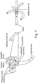
- Control unit 10 utilizes motors and servos for transferring user hand and finger movements at the interface to deflection of the endoscope shaft and operation of a tool provided through the working channel thereof.
- Control unit 10 includes a user interface 14 which includes a palm interface 16, dorsum interface 17 and a finger interface 18. Interface 14 will be described in greater detail below.
- Control unit 10 also includes a first drive mechanism 20 for translating movements of palm interface 16 to rotation of knobs 22 and 22' ( Figure 2b ) of endoscope 12.
- Drive mechanism 20 is an electro-mechanical device, which utilizes motors and gears to rotate knobs 22 and 22'.
- Control unit 10 further includes a second drive mechanism 24 for transforming movements of finger interface 18 into operation of a tool provided through the working channel of endoscope 12.
- Drive mechanism 24 is an electro-mechanical device that includes one or more motors/servos and gears to operate a manually operative end of a tool.
- User interface 14 can include additional interface elements including buttons and levers which enable wireless (WiFi, BT) control over peripheral instruments including a monitor (for displaying the endoscope camera image), a computer (for displaying files related to a procedure) or lighting.
- buttons and levers which enable wireless (WiFi, BT) control over peripheral instruments including a monitor (for displaying the endoscope camera image), a computer (for displaying files related to a procedure) or lighting.
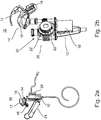
- Figure 2b illustrates control unit 10 with a portion of its housing removed to show gear cluster 30 and chip 32 that enable palm interface 16 to control the rotation of knobs 22.
- Chip 32 is electrically connected to user interface 14 and receives position sensor information therefrom. This information is then translated by chip 32 to command signals for drive mechanisms 20 and 24. Chip 32 can also be connected to external devices via wireless communication modes to enable a surgeon to control peripheral devices via interface 14.
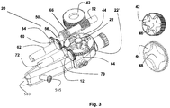
- Figure 3 illustrates first drive mechanism 20 in greater detail.
- Gears 42 and 44 (also shown separately on right) have shaped holes 46 and 48 (respectively) to complement the shape of knobs 22' and 22 of endoscope 12 (respectively).
- Gear 42 is fixed around the wings of knob 22 while gear 44 is fixed around knob 22'.
- a worm gear 50 is coupled to gear 42; and a worm gear 52 is coupled to gear 44.
- a gear 54 is fixed to a shaft 56 of worm gear 50 and engages a gear 60 driven by motor 62.
- Gear 64 is fixed to a shaft 66 (shown detached therefrom for clarity) of worm gear 52 and engages gear 70 driven by motor 72.
- Knobs 22 and 22' each articulates the distal end on a separate plane.
- the articulation planes of the distal end of the flexible endoscope are orthogonal, thus the combined movement of the distal end of the flexible tube produces spatial articulation allowing the surgeon to navigate the surgeon to a desired orientation.
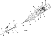
- FIGS 4a-b illustrate second drive mechanism 24, which is actuated by interface 18 in greater detail.
- Drive mechanism 24 includes a housing 70, which includes a neck region 72 and orientation wings 74. Wings 74 engage respective slots in control unit 10 to prevent housing 70 from freely rotating.
- Housing 70 can be fabricated from two halves, which are attached via screws, snaps and the like.
- Figure 4b illustrates the internal components of drive mechanism 24 and the distal end of endoscope 12 showing shaft 82 of tool 80 protruding from distal opening 115.
- the movements of components inside drive mechanism 24 are translated to movements of shaft 82 and grasper 83 as is indicated by R, L and C.
- An engagement element 76 is designed for holding a manual control end of a diagnostic or surgical tool 80 positionable through a working channel 13 of endoscope 12.
- element 76 is configured for holding a loop-type finger hold 78 of a tool 80 having grasper 83 effector end ( Figure 4a ), while opening 77 is designed for holding a barrel-type finger hold 79 of tool 80. Moving finger hold 78 with respect to finger hold 79 opens and closes jaws 83 of tool 80.
- Tool 80 is positioned with holds 76 and 79 as shown in Figure 4b and shaft 82 positioned through a lumen in housing 70 and out from an opening at neck region 72.
- Drive mechanism 24 is capable of 4 separate movements, rotating tool 80 (R) translating shaft 82 of tool 80 forwards and backwards 115 (L), and opening and closing the jaws of grasper 83 (C).
- drive mechanism 24 includes a motor 84 for driving a screw 86 into and out of a thread within cylinder 87.
- screw 86 rotates into cylinder 87 thereby sliding finger hold 76 with respect to finger hold 79 (C).
- An additional motor can rotate cylinder 87 thereby rotating tool 80 within drive mechanism 24.
- a tool 80 having control wires for steering a portion thereof can also be connected to drive mechanism 24.
- the control wires of such a tool can be linked to one or more motors of drive mechanism 24 via, for example, gears and rods to enable the motor(s) to selectively pull one or more control wires and deflect a steerable portion of the tool.
- user interface 14 of the present control unit enables simultaneous control over endoscope tip deflection and tool operation using a single hand.
- FIGS 5a-b describe user interface 14 in greater detail.
- User interface 14 includes a palm interface 16 which is able to pitch (P) and yaw (Y) simultaneously around axis 100 and 101. These rotations are done relative to a ball joint/gimbal pivot point and a sensor mechanism (not shown), located at the top of base 102.
- a hand H
- dorsum interface 17 supporting the back of the surgeon hand as described hereinabove.
- the resulting movement of the distal tip 118 of endoscope 12 is shown in Figure 6a .
- a home (neutral) position of palm interface 16 corresponds to a linear position (L) of distal tip 118, while pitch (P) and yaw (Y) of palm interface 16 results in tip 118 deflection as shown by arrows.
- Control over shaft 82 of tool 80 is effected via finger interface 18.
- Pads 106 of interface 18 are used to control the opening and closing of the jaws. As is shown in Figure 5b , the index finger and thumb of the surgeon engage pads 106 allowing opening and closing of the jaws by pressing in and releasing pads 106. Rotation of the jaws is controlled by rotating housing 108 around base 113. Interface 18 allows the surgeon to simultaneously control both rotation of the jaws and their opening and closing using two fingers. Housing 108 can also be pulled out and pushed in relative to base 113.
- a linear sensor located at base 113 of housing 108 allows the surgeon to control the distance the distal end of shaft 82 protrudes from the distal opening 115 ( Figure 6b ) of the working channel.
- the linear sensor may be simple micro switch with 3 contacts (forward backward and neutral) or may be any analog or digital sensor that measures linear travel.
- Figure 6b illustrates shaft rotation (R), grasper closing and opening (C) and shaft translation (L) of tool 80 in response to rotation of housing 108, pressing in and releasing pads 106 and pushing pulling housing 108 (respectively).
- a prototype of the present control unit was fabricated and tested with a standard flexible endoscope.
- the prototype included a 3D printed body housing a first drive mechanism for driving endoscope steering via a palm interface and a second drive mechanism for rotating and extending/retracting a grasper tool as well as actuating the jaws thereof.
- control unit was attached onto the endoscope and the resulting assembly ( Figure 7 ) was bench tested for functionality including deflection of the endoscope tip, and actuation of a grasper tool positioned through the working channel of the endoscope.
- control unit which are, for clarity, described in the context of separate embodiments, may also be provided in combination in a single embodiment. Conversely, various features of the control unit, which are, for brevity, described in the context of a single embodiment, may also be provided separately or in any suitable subcombination.
Landscapes
- Health & Medical Sciences (AREA)
- Life Sciences & Earth Sciences (AREA)
- Surgery (AREA)
- Engineering & Computer Science (AREA)
- Veterinary Medicine (AREA)
- Public Health (AREA)
- General Health & Medical Sciences (AREA)
- Animal Behavior & Ethology (AREA)
- Biomedical Technology (AREA)
- Heart & Thoracic Surgery (AREA)
- Biophysics (AREA)
- Molecular Biology (AREA)
- Nuclear Medicine, Radiotherapy & Molecular Imaging (AREA)
- Medical Informatics (AREA)
- Physics & Mathematics (AREA)
- Radiology & Medical Imaging (AREA)
- Pathology (AREA)
- Optics & Photonics (AREA)
- Pulmonology (AREA)
- Anesthesiology (AREA)
- Hematology (AREA)
- Ophthalmology & Optometry (AREA)
- Mechanical Engineering (AREA)
- Endoscopes (AREA)
- Instruments For Viewing The Inside Of Hollow Bodies (AREA)
- Surgical Instruments (AREA)
Applications Claiming Priority (2)
| Application Number | Priority Date | Filing Date | Title |
|---|---|---|---|
| US201562203421P | 2015-08-11 | 2015-08-11 | |
| PCT/IL2016/050879 WO2017025969A1 (en) | 2015-08-11 | 2016-08-11 | Control unit for a flexible endoscope |
Publications (3)
| Publication Number | Publication Date |
|---|---|
| EP3334323A1 EP3334323A1 (en) | 2018-06-20 |
| EP3334323A4 EP3334323A4 (en) | 2019-05-15 |
| EP3334323B1 true EP3334323B1 (en) | 2020-06-24 |
Family
ID=57983566
Family Applications (1)
| Application Number | Title | Priority Date | Filing Date |
|---|---|---|---|
| EP16834773.0A Active EP3334323B1 (en) | 2015-08-11 | 2016-08-11 | Control unit attachable to an endoscope having a shaft deflectable via two rotatable knobs to allow one-handed operation of the knobs |
Country Status (13)
Families Citing this family (11)
| Publication number | Priority date | Publication date | Assignee | Title |
|---|---|---|---|---|
| CA2984729C (en) | 2015-08-11 | 2024-02-27 | Mordehai Sholev | Control unit for a flexible endoscope |
| IT201800004478A1 (it) * | 2018-04-13 | 2019-10-13 | Sistema di comando per dispositivo medico utilizzabile nell’ambito di un endoscopio. | |
| US11504147B2 (en) | 2018-05-18 | 2022-11-22 | Vascular Technology, Incorporated | Articulating microsurgical instrument |
| WO2020049718A1 (ja) * | 2018-09-07 | 2020-03-12 | オリンパス株式会社 | マニピュレータシステム |
| WO2020144731A1 (ja) * | 2019-01-07 | 2020-07-16 | オリンパス株式会社 | 内視鏡 |
| DE102019201277A1 (de) | 2019-01-31 | 2020-08-06 | Deutsches Zentrum für Luft- und Raumfahrt e.V. | Vorrichtung zur Führung eines medizinischen flexiblen Schafts |
| KR102793231B1 (ko) * | 2019-11-18 | 2025-04-07 | 한국전기연구원 | 전자동 내시경 시스템 |
| FR3103696B1 (fr) * | 2019-12-03 | 2024-12-20 | Institut Hospitalo Univ De Chirurgie Mini Invasive Guidee Par Limage | Module d’actionnement motorisé d’un instrument endoscopique |
| US20230104573A1 (en) * | 2020-02-26 | 2023-04-06 | Human Xtensions Ltd. | Control system for a colonoscope |
| US12178404B2 (en) * | 2020-09-29 | 2024-12-31 | Boston Scientific Scimed, Inc. | Medical device controller |
| WO2024182350A1 (en) * | 2023-02-28 | 2024-09-06 | Boston Scientific Scimed, Inc. | Medical systems, devices, and related methods for rotatably or pivotably coupling medical devices |
Citations (1)
| Publication number | Priority date | Publication date | Assignee | Title |
|---|---|---|---|---|
| US20040059191A1 (en) * | 2002-06-17 | 2004-03-25 | Robert Krupa | Mechanical steering mechanism for borescopes, endoscopes, catheters, guide tubes, and working tools |
Family Cites Families (37)
| Publication number | Priority date | Publication date | Assignee | Title |
|---|---|---|---|---|
| JPS53873A (en) * | 1976-06-23 | 1978-01-07 | Mitsubishi Electric Corp | Fluid blowwout breaker |
| GB2070715A (en) * | 1980-02-14 | 1981-09-09 | Welch Allyn Inc | Endoscope |
| JPH0255907A (ja) | 1988-08-20 | 1990-02-26 | Juki Corp | 形状認識装置 |
| JPH0642644Y2 (ja) * | 1988-10-15 | 1994-11-09 | オリンパス光学工業株式会社 | 内視鏡湾曲装置 |
| JP3222190B2 (ja) * | 1992-04-28 | 2001-10-22 | オリンパス光学工業株式会社 | 内視鏡用湾曲制御装置 |
| JPH1132977A (ja) * | 1997-07-17 | 1999-02-09 | Olympus Optical Co Ltd | 内視鏡装置 |
| US20020171625A1 (en) | 2001-05-15 | 2002-11-21 | Jona Group, Ltd. | Pistol-grip trackball mouse |
| JP2003010112A (ja) | 2001-06-28 | 2003-01-14 | Olympus Optical Co Ltd | 内視鏡システム |
| JP4615906B2 (ja) * | 2004-06-17 | 2011-01-19 | オリンパス株式会社 | 内視鏡及び内視鏡用湾曲操作補助部材 |
| CN100577085C (zh) * | 2004-12-03 | 2010-01-06 | 奥林巴斯株式会社 | 插入部拆装式电动弯曲内窥镜 |
| WO2006059721A1 (ja) * | 2004-12-03 | 2006-06-08 | Olympus Corporation | 挿入部着脱式電動湾曲内視鏡 |
| US7618413B2 (en) * | 2005-06-22 | 2009-11-17 | Boston Scientific Scimed, Inc. | Medical device control system |
| JP4728075B2 (ja) | 2005-09-28 | 2011-07-20 | オリンパスメディカルシステムズ株式会社 | 内視鏡システム |
| JP2011510789A (ja) * | 2008-02-07 | 2011-04-07 | ザ トラスティーズ オブ コロンビア ユニバーシティ イン ザ シティ オブ ニューヨーク | 遠隔内視鏡ハンドルマニピュレーション |
| US8419623B2 (en) * | 2009-01-28 | 2013-04-16 | Cani Optical Systems, Llc | Portable endoscope for diverse medical disciplines |
| JP5500844B2 (ja) * | 2009-03-18 | 2014-05-21 | 富士フイルム株式会社 | 内視鏡 |
| FR2948594B1 (fr) * | 2009-07-31 | 2012-07-20 | Dexterite Surgical | Manipulateur ergonomique et semi-automatique et applications aux instruments pour chirurgie mini-invasive |
| US8543240B2 (en) * | 2009-11-13 | 2013-09-24 | Intuitive Surgical Operations, Inc. | Master finger tracking device and method of use in a minimally invasive surgical system |
| WO2012117865A1 (ja) | 2011-02-28 | 2012-09-07 | オリンパスメディカルシステムズ株式会社 | 湾曲部付医療装置 |
| WO2012127462A1 (en) * | 2011-03-22 | 2012-09-27 | Human Extensions Ltd. | Motorized surgical instruments |
| US9901412B2 (en) * | 2011-04-29 | 2018-02-27 | Vanderbilt University | Dexterous surgical manipulator and method of use |
| EP2702923A4 (en) * | 2011-06-16 | 2014-11-05 | Olympus Medical Systems Corp | ENDOSCOPE |
| CN103458807B (zh) * | 2011-09-08 | 2016-05-18 | 奥林巴斯株式会社 | 多自由度钳子 |
| DE202013012268U1 (de) * | 2012-02-29 | 2016-02-24 | M.S.T. Medical Surgery Technologies Ltd. | Manuelles Steuersystem zum Manövrieren eines Endoskops |
| US20140275763A1 (en) | 2013-03-15 | 2014-09-18 | Lucent Medical Systems, Inc. | Partially disposable endoscopic device |
| US9949623B2 (en) * | 2013-05-17 | 2018-04-24 | Endochoice, Inc. | Endoscope control unit with braking system |
| US20160271385A1 (en) * | 2013-07-11 | 2016-09-22 | Transenterix Surgical, Inc. | Surgical instruments, systems, and methods for coupling of electrical energy to surgical instruments |
| KR20160052626A (ko) * | 2013-09-01 | 2016-05-12 | 휴먼 익스텐션스 리미티드 | 의료 장치용 제어 유닛 |
| WO2015038290A1 (en) * | 2013-09-12 | 2015-03-19 | Endocon, Inc. | Power-assisted medical scope |
| WO2015077584A2 (en) * | 2013-11-22 | 2015-05-28 | Massachusetts Institute Of Technology | Steering techniques for surgical instruments |
| EP3158910A4 (en) * | 2014-06-20 | 2018-03-14 | Olympus Corporation | Endoscope device |
| JP6110828B2 (ja) * | 2014-09-30 | 2017-04-05 | 富士フイルム株式会社 | 内視鏡装置 |
| JP6013672B1 (ja) * | 2014-12-10 | 2016-10-25 | オリンパス株式会社 | 内視鏡システム |
| US10085622B2 (en) * | 2014-12-15 | 2018-10-02 | Gyrus Acmi, Inc. | Control of a basket retrieval device |
| JP6076556B1 (ja) * | 2015-03-18 | 2017-02-08 | オリンパス株式会社 | 湾曲操作装置及び内視鏡 |
| WO2016199485A1 (ja) * | 2015-06-08 | 2016-12-15 | オリンパス株式会社 | 湾曲操作装置および内視鏡 |
| CA2984729C (en) | 2015-08-11 | 2024-02-27 | Mordehai Sholev | Control unit for a flexible endoscope |
-
2016
- 2016-08-11 CA CA2984729A patent/CA2984729C/en active Active
- 2016-08-11 AU AU2016306164A patent/AU2016306164A1/en not_active Abandoned
- 2016-08-11 ES ES16834773T patent/ES2821101T3/es active Active
- 2016-08-11 EP EP16834773.0A patent/EP3334323B1/en active Active
- 2016-08-11 DK DK16834773.0T patent/DK3334323T3/da active
- 2016-08-11 WO PCT/IL2016/050879 patent/WO2017025969A1/en active Application Filing
- 2016-08-11 US US15/565,177 patent/US10835108B2/en active Active
- 2016-08-11 CN CN201680029036.XA patent/CN107847105B/zh active Active
- 2016-08-11 BR BR112017026204-5A patent/BR112017026204A2/pt not_active Application Discontinuation
- 2016-08-11 MX MX2017014628A patent/MX2017014628A/es unknown
- 2016-08-11 KR KR1020177035356A patent/KR102562929B1/ko active Active
- 2016-08-11 JP JP2017560595A patent/JP6845809B2/ja active Active
-
2017
- 2017-11-22 IL IL255861A patent/IL255861A/en unknown
Patent Citations (1)
| Publication number | Priority date | Publication date | Assignee | Title |
|---|---|---|---|---|
| US20040059191A1 (en) * | 2002-06-17 | 2004-03-25 | Robert Krupa | Mechanical steering mechanism for borescopes, endoscopes, catheters, guide tubes, and working tools |
Also Published As
| Publication number | Publication date |
|---|---|
| KR20180038417A (ko) | 2018-04-16 |
| KR102562929B1 (ko) | 2023-08-03 |
| US20180098687A1 (en) | 2018-04-12 |
| CA2984729C (en) | 2024-02-27 |
| US10835108B2 (en) | 2020-11-17 |
| CN107847105B (zh) | 2021-01-26 |
| WO2017025969A1 (en) | 2017-02-16 |
| MX2017014628A (es) | 2018-06-06 |
| BR112017026204A2 (pt) | 2018-09-04 |
| EP3334323A1 (en) | 2018-06-20 |
| AU2016306164A1 (en) | 2017-11-30 |
| DK3334323T3 (da) | 2020-09-28 |
| JP6845809B2 (ja) | 2021-03-24 |
| ES2821101T3 (es) | 2021-04-23 |
| CN107847105A (zh) | 2018-03-27 |
| JP2018526042A (ja) | 2018-09-13 |
| CA2984729A1 (en) | 2017-02-16 |
| IL255861A (en) | 2018-01-31 |
| EP3334323A4 (en) | 2019-05-15 |
Similar Documents
| Publication | Publication Date | Title |
|---|---|---|
| EP3334323B1 (en) | Control unit attachable to an endoscope having a shaft deflectable via two rotatable knobs to allow one-handed operation of the knobs | |
| US11020197B2 (en) | Control unit for a medical device | |
| AU2017203633C1 (en) | Robotic systems, robotic system user interfaces, human interface devices for controlling robotic systems and methods of controlling robotic systems | |
| US12295604B2 (en) | Control unit for a medical device | |
| JP7187311B2 (ja) | 内視鏡装置 | |
| CN107848106B (zh) | 操纵器系统 | |
| HK1253926B (en) | Control unit attachable to an endoscope having a shaft deflectable via two rotatable knobs to allow one-handed operation of the knobs | |
| HK1253926A1 (en) | Control unit attachable to an endoscope having a shaft deflectable via two rotatable knobs to allow one-handed operation of the knobs | |
| CN110772325A (zh) | 手柄及主操作台 | |
| CN210130920U (zh) | 手柄及主操作台 | |
| CN210130921U (zh) | 手柄及主操作台 | |
| US20230104573A1 (en) | Control system for a colonoscope | |
| HK40008022B (en) | Control unit for a medical device |
Legal Events
| Date | Code | Title | Description |
|---|---|---|---|
| STAA | Information on the status of an ep patent application or granted ep patent |
Free format text: STATUS: THE INTERNATIONAL PUBLICATION HAS BEEN MADE |
|
| PUAI | Public reference made under article 153(3) epc to a published international application that has entered the european phase |
Free format text: ORIGINAL CODE: 0009012 |
|
| STAA | Information on the status of an ep patent application or granted ep patent |
Free format text: STATUS: REQUEST FOR EXAMINATION WAS MADE |
|
| 17P | Request for examination filed |
Effective date: 20171122 |
|
| AK | Designated contracting states |
Kind code of ref document: A1 Designated state(s): AL AT BE BG CH CY CZ DE DK EE ES FI FR GB GR HR HU IE IS IT LI LT LU LV MC MK MT NL NO PL PT RO RS SE SI SK SM TR |
|
| AX | Request for extension of the european patent |
Extension state: BA ME |
|
| DAV | Request for validation of the european patent (deleted) | ||
| DAX | Request for extension of the european patent (deleted) | ||
| A4 | Supplementary search report drawn up and despatched |
Effective date: 20190412 |
|
| RIC1 | Information provided on ipc code assigned before grant |
Ipc: A61M 25/01 20060101ALI20190408BHEP Ipc: A61B 1/005 20060101ALI20190408BHEP Ipc: A61B 17/00 20060101ALI20190408BHEP Ipc: A61B 1/00 20060101AFI20190408BHEP Ipc: A61B 17/29 20060101ALI20190408BHEP |
|
| REG | Reference to a national code |
Ref country code: HK Ref legal event code: DE Ref document number: 1253926 Country of ref document: HK |
|
| GRAP | Despatch of communication of intention to grant a patent |
Free format text: ORIGINAL CODE: EPIDOSNIGR1 |
|
| STAA | Information on the status of an ep patent application or granted ep patent |
Free format text: STATUS: GRANT OF PATENT IS INTENDED |
|
| INTG | Intention to grant announced |
Effective date: 20200122 |
|
| GRAS | Grant fee paid |
Free format text: ORIGINAL CODE: EPIDOSNIGR3 |
|
| GRAA | (expected) grant |
Free format text: ORIGINAL CODE: 0009210 |
|
| STAA | Information on the status of an ep patent application or granted ep patent |
Free format text: STATUS: THE PATENT HAS BEEN GRANTED |
|
| AK | Designated contracting states |
Kind code of ref document: B1 Designated state(s): AL AT BE BG CH CY CZ DE DK EE ES FI FR GB GR HR HU IE IS IT LI LT LU LV MC MK MT NL NO PL PT RO RS SE SI SK SM TR |
|
| REG | Reference to a national code |
Ref country code: GB Ref legal event code: FG4D |
|
| REG | Reference to a national code |
Ref country code: CH Ref legal event code: EP |
|
| REG | Reference to a national code |
Ref country code: AT Ref legal event code: REF Ref document number: 1283049 Country of ref document: AT Kind code of ref document: T Effective date: 20200715 |
|
| REG | Reference to a national code |
Ref country code: DE Ref legal event code: R096 Ref document number: 602016038871 Country of ref document: DE |
|
| REG | Reference to a national code |
Ref country code: IE Ref legal event code: FG4D |
|
| REG | Reference to a national code |
Ref country code: DK Ref legal event code: T3 Effective date: 20200922 |
|
| REG | Reference to a national code |
Ref country code: CH Ref legal event code: NV Representative=s name: IPRIME RENTSCH KAELIN AG, CH Ref country code: NL Ref legal event code: FP |
|
| PG25 | Lapsed in a contracting state [announced via postgrant information from national office to epo] |
Ref country code: GR Free format text: LAPSE BECAUSE OF FAILURE TO SUBMIT A TRANSLATION OF THE DESCRIPTION OR TO PAY THE FEE WITHIN THE PRESCRIBED TIME-LIMIT Effective date: 20200925 Ref country code: SE Free format text: LAPSE BECAUSE OF FAILURE TO SUBMIT A TRANSLATION OF THE DESCRIPTION OR TO PAY THE FEE WITHIN THE PRESCRIBED TIME-LIMIT Effective date: 20200624 Ref country code: LT Free format text: LAPSE BECAUSE OF FAILURE TO SUBMIT A TRANSLATION OF THE DESCRIPTION OR TO PAY THE FEE WITHIN THE PRESCRIBED TIME-LIMIT Effective date: 20200624 Ref country code: FI Free format text: LAPSE BECAUSE OF FAILURE TO SUBMIT A TRANSLATION OF THE DESCRIPTION OR TO PAY THE FEE WITHIN THE PRESCRIBED TIME-LIMIT Effective date: 20200624 |
|
| REG | Reference to a national code |
Ref country code: LT Ref legal event code: MG4D |
|
| REG | Reference to a national code |
Ref country code: NO Ref legal event code: T2 Effective date: 20200624 |
|
| PG25 | Lapsed in a contracting state [announced via postgrant information from national office to epo] |
Ref country code: HR Free format text: LAPSE BECAUSE OF FAILURE TO SUBMIT A TRANSLATION OF THE DESCRIPTION OR TO PAY THE FEE WITHIN THE PRESCRIBED TIME-LIMIT Effective date: 20200624 Ref country code: LV Free format text: LAPSE BECAUSE OF FAILURE TO SUBMIT A TRANSLATION OF THE DESCRIPTION OR TO PAY THE FEE WITHIN THE PRESCRIBED TIME-LIMIT Effective date: 20200624 Ref country code: BG Free format text: LAPSE BECAUSE OF FAILURE TO SUBMIT A TRANSLATION OF THE DESCRIPTION OR TO PAY THE FEE WITHIN THE PRESCRIBED TIME-LIMIT Effective date: 20200924 Ref country code: RS Free format text: LAPSE BECAUSE OF FAILURE TO SUBMIT A TRANSLATION OF THE DESCRIPTION OR TO PAY THE FEE WITHIN THE PRESCRIBED TIME-LIMIT Effective date: 20200624 |
|
| PG25 | Lapsed in a contracting state [announced via postgrant information from national office to epo] |
Ref country code: AL Free format text: LAPSE BECAUSE OF FAILURE TO SUBMIT A TRANSLATION OF THE DESCRIPTION OR TO PAY THE FEE WITHIN THE PRESCRIBED TIME-LIMIT Effective date: 20200624 |
|
| PG25 | Lapsed in a contracting state [announced via postgrant information from national office to epo] |
Ref country code: PT Free format text: LAPSE BECAUSE OF FAILURE TO SUBMIT A TRANSLATION OF THE DESCRIPTION OR TO PAY THE FEE WITHIN THE PRESCRIBED TIME-LIMIT Effective date: 20201026 Ref country code: CZ Free format text: LAPSE BECAUSE OF FAILURE TO SUBMIT A TRANSLATION OF THE DESCRIPTION OR TO PAY THE FEE WITHIN THE PRESCRIBED TIME-LIMIT Effective date: 20200624 Ref country code: RO Free format text: LAPSE BECAUSE OF FAILURE TO SUBMIT A TRANSLATION OF THE DESCRIPTION OR TO PAY THE FEE WITHIN THE PRESCRIBED TIME-LIMIT Effective date: 20200624 Ref country code: EE Free format text: LAPSE BECAUSE OF FAILURE TO SUBMIT A TRANSLATION OF THE DESCRIPTION OR TO PAY THE FEE WITHIN THE PRESCRIBED TIME-LIMIT Effective date: 20200624 Ref country code: SM Free format text: LAPSE BECAUSE OF FAILURE TO SUBMIT A TRANSLATION OF THE DESCRIPTION OR TO PAY THE FEE WITHIN THE PRESCRIBED TIME-LIMIT Effective date: 20200624 |
|
| PG25 | Lapsed in a contracting state [announced via postgrant information from national office to epo] |
Ref country code: IS Free format text: LAPSE BECAUSE OF FAILURE TO SUBMIT A TRANSLATION OF THE DESCRIPTION OR TO PAY THE FEE WITHIN THE PRESCRIBED TIME-LIMIT Effective date: 20201024 Ref country code: SK Free format text: LAPSE BECAUSE OF FAILURE TO SUBMIT A TRANSLATION OF THE DESCRIPTION OR TO PAY THE FEE WITHIN THE PRESCRIBED TIME-LIMIT Effective date: 20200624 Ref country code: PL Free format text: LAPSE BECAUSE OF FAILURE TO SUBMIT A TRANSLATION OF THE DESCRIPTION OR TO PAY THE FEE WITHIN THE PRESCRIBED TIME-LIMIT Effective date: 20200624 |
|
| REG | Reference to a national code |
Ref country code: DE Ref legal event code: R097 Ref document number: 602016038871 Country of ref document: DE |
|
| PG25 | Lapsed in a contracting state [announced via postgrant information from national office to epo] |
Ref country code: MC Free format text: LAPSE BECAUSE OF FAILURE TO SUBMIT A TRANSLATION OF THE DESCRIPTION OR TO PAY THE FEE WITHIN THE PRESCRIBED TIME-LIMIT Effective date: 20200624 |
|
| REG | Reference to a national code |
Ref country code: ES Ref legal event code: FG2A Ref document number: 2821101 Country of ref document: ES Kind code of ref document: T3 Effective date: 20210423 |
|
| PG25 | Lapsed in a contracting state [announced via postgrant information from national office to epo] |
Ref country code: LU Free format text: LAPSE BECAUSE OF NON-PAYMENT OF DUE FEES Effective date: 20200811 |
|
| PLBE | No opposition filed within time limit |
Free format text: ORIGINAL CODE: 0009261 |
|
| STAA | Information on the status of an ep patent application or granted ep patent |
Free format text: STATUS: NO OPPOSITION FILED WITHIN TIME LIMIT |
|
| 26N | No opposition filed |
Effective date: 20210325 |
|
| PG25 | Lapsed in a contracting state [announced via postgrant information from national office to epo] |
Ref country code: SI Free format text: LAPSE BECAUSE OF FAILURE TO SUBMIT A TRANSLATION OF THE DESCRIPTION OR TO PAY THE FEE WITHIN THE PRESCRIBED TIME-LIMIT Effective date: 20200624 |
|
| REG | Reference to a national code |
Ref country code: AT Ref legal event code: UEP Ref document number: 1283049 Country of ref document: AT Kind code of ref document: T Effective date: 20200624 |
|
| PG25 | Lapsed in a contracting state [announced via postgrant information from national office to epo] |
Ref country code: MT Free format text: LAPSE BECAUSE OF FAILURE TO SUBMIT A TRANSLATION OF THE DESCRIPTION OR TO PAY THE FEE WITHIN THE PRESCRIBED TIME-LIMIT Effective date: 20200624 Ref country code: CY Free format text: LAPSE BECAUSE OF FAILURE TO SUBMIT A TRANSLATION OF THE DESCRIPTION OR TO PAY THE FEE WITHIN THE PRESCRIBED TIME-LIMIT Effective date: 20200624 |
|
| PG25 | Lapsed in a contracting state [announced via postgrant information from national office to epo] |
Ref country code: MK Free format text: LAPSE BECAUSE OF FAILURE TO SUBMIT A TRANSLATION OF THE DESCRIPTION OR TO PAY THE FEE WITHIN THE PRESCRIBED TIME-LIMIT Effective date: 20200624 |
|
| PGFP | Annual fee paid to national office [announced via postgrant information from national office to epo] |
Ref country code: TR Payment date: 20220804 Year of fee payment: 7 Ref country code: NO Payment date: 20220824 Year of fee payment: 7 Ref country code: IE Payment date: 20220825 Year of fee payment: 7 Ref country code: DK Payment date: 20220824 Year of fee payment: 7 Ref country code: AT Payment date: 20220822 Year of fee payment: 7 |
|
| PGFP | Annual fee paid to national office [announced via postgrant information from national office to epo] |
Ref country code: BE Payment date: 20220819 Year of fee payment: 7 |
|
| P01 | Opt-out of the competence of the unified patent court (upc) registered |
Effective date: 20230517 |
|
| REG | Reference to a national code |
Ref country code: DK Ref legal event code: EBP Effective date: 20230831 |
|
| REG | Reference to a national code |
Ref country code: AT Ref legal event code: MM01 Ref document number: 1283049 Country of ref document: AT Kind code of ref document: T Effective date: 20230811 |
|
| PG25 | Lapsed in a contracting state [announced via postgrant information from national office to epo] |
Ref country code: AT Free format text: LAPSE BECAUSE OF NON-PAYMENT OF DUE FEES Effective date: 20230811 |
|
| PG25 | Lapsed in a contracting state [announced via postgrant information from national office to epo] |
Ref country code: AT Free format text: LAPSE BECAUSE OF NON-PAYMENT OF DUE FEES Effective date: 20230811 |
|
| REG | Reference to a national code |
Ref country code: BE Ref legal event code: MM Effective date: 20230831 |
|
| REG | Reference to a national code |
Ref country code: IE Ref legal event code: MM4A |
|
| PG25 | Lapsed in a contracting state [announced via postgrant information from national office to epo] |
Ref country code: NO Free format text: LAPSE BECAUSE OF NON-PAYMENT OF DUE FEES Effective date: 20230831 |
|
| PG25 | Lapsed in a contracting state [announced via postgrant information from national office to epo] |
Ref country code: IE Free format text: LAPSE BECAUSE OF NON-PAYMENT OF DUE FEES Effective date: 20230811 |
|
| PG25 | Lapsed in a contracting state [announced via postgrant information from national office to epo] |
Ref country code: DK Free format text: LAPSE BECAUSE OF NON-PAYMENT OF DUE FEES Effective date: 20230831 |
|
| PG25 | Lapsed in a contracting state [announced via postgrant information from national office to epo] |
Ref country code: IE Free format text: LAPSE BECAUSE OF NON-PAYMENT OF DUE FEES Effective date: 20230811 Ref country code: DK Free format text: LAPSE BECAUSE OF NON-PAYMENT OF DUE FEES Effective date: 20230831 |
|
| PG25 | Lapsed in a contracting state [announced via postgrant information from national office to epo] |
Ref country code: BE Free format text: LAPSE BECAUSE OF NON-PAYMENT OF DUE FEES Effective date: 20230831 |
|
| PGFP | Annual fee paid to national office [announced via postgrant information from national office to epo] |
Ref country code: NL Payment date: 20240821 Year of fee payment: 9 |
|
| PGFP | Annual fee paid to national office [announced via postgrant information from national office to epo] |
Ref country code: DE Payment date: 20240821 Year of fee payment: 9 |
|
| PGFP | Annual fee paid to national office [announced via postgrant information from national office to epo] |
Ref country code: GB Payment date: 20240826 Year of fee payment: 9 |
|
| PGFP | Annual fee paid to national office [announced via postgrant information from national office to epo] |
Ref country code: FR Payment date: 20240829 Year of fee payment: 9 |
|
| PGFP | Annual fee paid to national office [announced via postgrant information from national office to epo] |
Ref country code: ES Payment date: 20240927 Year of fee payment: 9 Ref country code: CH Payment date: 20240901 Year of fee payment: 9 |
|
| PGFP | Annual fee paid to national office [announced via postgrant information from national office to epo] |
Ref country code: IT Payment date: 20240827 Year of fee payment: 9 |