US20180098687A1 - Control unit for a flexible endoscope - Google Patents
Control unit for a flexible endoscope Download PDFInfo
- Publication number
- US20180098687A1 US20180098687A1 US15/565,177 US201615565177A US2018098687A1 US 20180098687 A1 US20180098687 A1 US 20180098687A1 US 201615565177 A US201615565177 A US 201615565177A US 2018098687 A1 US2018098687 A1 US 2018098687A1
- Authority
- US
- United States
- Prior art keywords
- interface
- control unit
- endoscope
- shaft
- drive mechanism
- Prior art date
- Legal status (The legal status is an assumption and is not a legal conclusion. Google has not performed a legal analysis and makes no representation as to the accuracy of the status listed.)
- Granted
Links
Images
Classifications
-
- A—HUMAN NECESSITIES
- A61—MEDICAL OR VETERINARY SCIENCE; HYGIENE
- A61B—DIAGNOSIS; SURGERY; IDENTIFICATION
- A61B1/00—Instruments for performing medical examinations of the interior of cavities or tubes of the body by visual or photographical inspection, e.g. endoscopes; Illuminating arrangements therefor
- A61B1/00002—Operational features of endoscopes
- A61B1/00039—Operational features of endoscopes provided with input arrangements for the user
- A61B1/00042—Operational features of endoscopes provided with input arrangements for the user for mechanical operation
-
- A—HUMAN NECESSITIES
- A61—MEDICAL OR VETERINARY SCIENCE; HYGIENE
- A61B—DIAGNOSIS; SURGERY; IDENTIFICATION
- A61B1/00—Instruments for performing medical examinations of the interior of cavities or tubes of the body by visual or photographical inspection, e.g. endoscopes; Illuminating arrangements therefor
- A61B1/00064—Constructional details of the endoscope body
- A61B1/00066—Proximal part of endoscope body, e.g. handles
-
- A—HUMAN NECESSITIES
- A61—MEDICAL OR VETERINARY SCIENCE; HYGIENE
- A61B—DIAGNOSIS; SURGERY; IDENTIFICATION
- A61B1/00—Instruments for performing medical examinations of the interior of cavities or tubes of the body by visual or photographical inspection, e.g. endoscopes; Illuminating arrangements therefor
- A61B1/00131—Accessories for endoscopes
- A61B1/00133—Drive units for endoscopic tools inserted through or with the endoscope
-
- A—HUMAN NECESSITIES
- A61—MEDICAL OR VETERINARY SCIENCE; HYGIENE
- A61B—DIAGNOSIS; SURGERY; IDENTIFICATION
- A61B1/00—Instruments for performing medical examinations of the interior of cavities or tubes of the body by visual or photographical inspection, e.g. endoscopes; Illuminating arrangements therefor
- A61B1/00147—Holding or positioning arrangements
- A61B1/0016—Holding or positioning arrangements using motor drive units
-
- A—HUMAN NECESSITIES
- A61—MEDICAL OR VETERINARY SCIENCE; HYGIENE
- A61B—DIAGNOSIS; SURGERY; IDENTIFICATION
- A61B1/00—Instruments for performing medical examinations of the interior of cavities or tubes of the body by visual or photographical inspection, e.g. endoscopes; Illuminating arrangements therefor
- A61B1/005—Flexible endoscopes
- A61B1/0051—Flexible endoscopes with controlled bending of insertion part
- A61B1/0052—Constructional details of control elements, e.g. handles
-
- A—HUMAN NECESSITIES
- A61—MEDICAL OR VETERINARY SCIENCE; HYGIENE
- A61B—DIAGNOSIS; SURGERY; IDENTIFICATION
- A61B1/00—Instruments for performing medical examinations of the interior of cavities or tubes of the body by visual or photographical inspection, e.g. endoscopes; Illuminating arrangements therefor
- A61B1/04—Instruments for performing medical examinations of the interior of cavities or tubes of the body by visual or photographical inspection, e.g. endoscopes; Illuminating arrangements therefor combined with photographic or television appliances
- A61B1/045—Control thereof
-
- A—HUMAN NECESSITIES
- A61—MEDICAL OR VETERINARY SCIENCE; HYGIENE
- A61B—DIAGNOSIS; SURGERY; IDENTIFICATION
- A61B17/00—Surgical instruments, devices or methods
- A61B17/28—Surgical forceps
- A61B17/29—Forceps for use in minimally invasive surgery
-
- A—HUMAN NECESSITIES
- A61—MEDICAL OR VETERINARY SCIENCE; HYGIENE
- A61M—DEVICES FOR INTRODUCING MEDIA INTO, OR ONTO, THE BODY; DEVICES FOR TRANSDUCING BODY MEDIA OR FOR TAKING MEDIA FROM THE BODY; DEVICES FOR PRODUCING OR ENDING SLEEP OR STUPOR
- A61M25/00—Catheters; Hollow probes
- A61M25/01—Introducing, guiding, advancing, emplacing or holding catheters
- A61M25/0105—Steering means as part of the catheter or advancing means; Markers for positioning
- A61M25/0133—Tip steering devices
- A61M25/0136—Handles therefor
-
- A—HUMAN NECESSITIES
- A61—MEDICAL OR VETERINARY SCIENCE; HYGIENE
- A61B—DIAGNOSIS; SURGERY; IDENTIFICATION
- A61B17/00—Surgical instruments, devices or methods
- A61B17/00234—Surgical instruments, devices or methods for minimally invasive surgery
- A61B2017/00292—Surgical instruments, devices or methods for minimally invasive surgery mounted on or guided by flexible, e.g. catheter-like, means
- A61B2017/003—Steerable
-
- A—HUMAN NECESSITIES
- A61—MEDICAL OR VETERINARY SCIENCE; HYGIENE
- A61B—DIAGNOSIS; SURGERY; IDENTIFICATION
- A61B17/00—Surgical instruments, devices or methods
- A61B17/00234—Surgical instruments, devices or methods for minimally invasive surgery
- A61B2017/00292—Surgical instruments, devices or methods for minimally invasive surgery mounted on or guided by flexible, e.g. catheter-like, means
- A61B2017/0034—Surgical instruments, devices or methods for minimally invasive surgery mounted on or guided by flexible, e.g. catheter-like, means adapted to be inserted through a working channel of an endoscope
-
- A—HUMAN NECESSITIES
- A61—MEDICAL OR VETERINARY SCIENCE; HYGIENE
- A61B—DIAGNOSIS; SURGERY; IDENTIFICATION
- A61B17/00—Surgical instruments, devices or methods
- A61B2017/00367—Details of actuation of instruments, e.g. relations between pushing buttons, or the like, and activation of the tool, working tip, or the like
- A61B2017/00398—Details of actuation of instruments, e.g. relations between pushing buttons, or the like, and activation of the tool, working tip, or the like using powered actuators, e.g. stepper motors, solenoids
-
- A—HUMAN NECESSITIES
- A61—MEDICAL OR VETERINARY SCIENCE; HYGIENE
- A61B—DIAGNOSIS; SURGERY; IDENTIFICATION
- A61B17/00—Surgical instruments, devices or methods
- A61B2017/0042—Surgical instruments, devices or methods with special provisions for gripping
- A61B2017/00424—Surgical instruments, devices or methods with special provisions for gripping ergonomic, e.g. fitting in fist
-
- A—HUMAN NECESSITIES
- A61—MEDICAL OR VETERINARY SCIENCE; HYGIENE
- A61B—DIAGNOSIS; SURGERY; IDENTIFICATION
- A61B17/00—Surgical instruments, devices or methods
- A61B17/28—Surgical forceps
- A61B17/29—Forceps for use in minimally invasive surgery
- A61B17/2909—Handles
- A61B2017/291—Handles the position of the handle being adjustable with respect to the shaft
Definitions
- the present invention relates to a control unit that is attachable to a flexible endoscope and can be used to control both tip deflection and a working channel-positioned tool using a single hand.
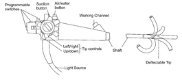
- Flexible endoscopes consist of a control head and a flexible shaft with a maneuverable tip.
- the head is connected to a light source via an ‘umbilical’ cord, through which pass other tubes transmitting air, water and suction, etc.
- the working channel is used for the passage of diagnostic or therapeutic tools.
- Two side-by-side mounted rotatable knobs are mounted on the side of the control head and are used for up/down and right/left movement of the shaft tip.
- knobs can be used to control the angle of the tip in any direction, however, such control requires use of both hands rendering simultaneous control over any other instrument (e.g. diagnostic or therapeutic tool positioned through the working channel) impossible.
- the control knobs of standard flexible endoscopes incorporate a friction braking system, so that the tip can be fixed temporarily in any desired position thus freeing the operator to control other instruments.
- control unit which enables an operator to control the tip of a flexible endoscope as well as a tool positioned through the working channel thereof using a single hand.
- a control unit attachable to an endoscope having a shaft deflectable via two rotatable knobs
- the control unit comprising: (a) a user interface including a first interface being mounted on a pivotal support attached to a housing of the control unit, the first interface being engageable by a palm of a hand; and (b) a drive unit operable via the user interface, the drive unit including a first drive mechanism for engaging the two rotatable knobs thereby allowing a user to control deflection of the shaft of the endoscope via the first interface.
- a first rotatable knob of the two rotatable knobs controls up/down deflection of the shaft and a second rotatable knob of the two rotatable knobs controls left/right deflection of the shaft and further wherein the first interface controls both up/down and left/right deflection of the shaft.
- the first drive mechanism includes at least one motor operable via the first interface.
- the at least one motor operates the two knobs.
- the drive mechanism includes a set of gears interposed between the at least one motor and the two knobs.
- the drive unit further comprises a second drive mechanism for engaging a manually operable end of a surgical tool positionable through a working channel of the endoscope.
- control unit further comprises a second interface being pivotally attached to the first interface and being engageable by one or more fingers of the hand, the second interface being for operating the surgical tool through the second drive mechanism.
- control unit further comprises a restraint being pivotally attached to the first interface and having an element capable of elastically deforming to apply a restraining force to a back of the hand when the palm is engaged with the first interface.
- the pivotal support is gimbaled.
- the second interface includes pads simultaneously operable via thumb and index finger of the hand.
- the second drive mechanism includes a servo.
- control unit further comprising a third interface for wirelessly controlling a remote device.
- the surgical tool includes a steerable shaft and an effector end controllable via the second interface.
- the present invention successfully addresses the shortcomings of the presently known configurations by providing a control unit for a flexible endoscope, which enables an operator to control the endoscope as well as a tool mounted therein via a single hand.
- FIG. 1 is a prior art drawing of a standard flexible endoscope.
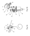
- FIGS. 2 a - b illustrate the present control unit mounted on an endoscope ( FIG. 2 a ) and the interface and drive mechanism components of the control unit ( FIG. 2 b ).
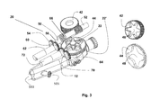
- FIG. 3 illustrates the first drive mechanism for controlling the rotatable knobs of the endoscope.
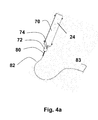
- FIGS. 4 a - b illustrate the second drive mechanism with attached tool.
- FIGS. 5 a - b illustrate the various interfaces of the user interface of the present control unit ( FIG. 5 a ) and their engagement to a user's hand ( FIG. 5 b ).
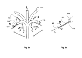
- FIGS. 6 a - b illustrate actuation of the endoscope tip ( FIG. 6 a ) and a working channel tool ( FIG. 6 b ) via the user interface.
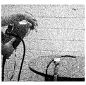
- FIG. 7 is an image of a prototype control unit connected to a standard flexible endoscope.
- the present invention is of a control unit which can be used to control the movement of a flexible endoscope tip, as well as the movement and function of a tool positioned through a working channel thereof.
- Endoscopic procedures require a surgeon to control both the endoscope and its associated tools (e.g. working channel tools). Since standard flexible endoscopes require both hands for tip deflection control, a surgeon cannot simultaneously control both endoscope and a surgical/therapeutic tool positioned through a working channel thereof.
- tools e.g. working channel tools
- control unit which can be attached to a standard flexible endoscope and enable a surgeon to control both endoscope and a diagnostic/therapeutic tool (as well as other additional peripheral tools) using a single hand.
- control unit of the present invention can be retrofitted onto any flexible endoscope without modifications to the endoscope control head.
- a control unit for a standard flexible endoscope encompasses any endoscope with a deflectable tip controllable via rotatable knobs.
- Such an endoscope preferably includes a camera for imaging an anatomical region of interest.
- the control unit includes a drive unit with attached user interface.
- the interface is operated by a single hand of a user and actuates motors and gears/levers/wires within the control unit to thereby control the endoscope and diagnostic/therapeutic tool positioned therethrough.
- the user interface has separate controls for endoscope tip deflection and the diagnostic/therapeutic tool.
- the user interface includes a first interface which is mounted on a pivotal support (e.g. gimbaled) attached to a housing of the control unit.
- the first interface is engageable by a palm of a hand and enables the user to control deflection of the endoscope tip in any direction via a first drive mechanism of the drive unit.
- the control unit further includes a restraint, which forms a part of the first interface and includes an element that is capable of elastically deforming to apply a restraining force to a back of the hand (dorsum) when the palm is engaged with the first interface.
- a restraint which forms a part of the first interface and includes an element that is capable of elastically deforming to apply a restraining force to a back of the hand (dorsum) when the palm is engaged with the first interface.
- the element elastically deforms and applies a downward force to the back of the hand thus maintaining the hand against the first interface and enabling precise control of this interface, as well as, enabling the user to pull up on the endoscope.
- the control unit also includes a second interface, which is pivotally attached to the first interface and is engageable by one or more fingers of the hand.
- the second interface controls the operation of a tool positioned through the working channel and attached to a second drive mechanism of the drive unit.
- the second interface can control an effector end of the tool (e.g., opening and closing a grasper), rotate or translate the shaft thereof and/or deflect a steerable portion thereof.
- the user interface of the present invention provides these three functions via movement of three separate limb joint and muscle groups:
- the endoscope is moved up and down and side to side with respect to body by arm movement (primarily about the elbow and/or shoulder joints).
- the shaft of the endoscope is deflected via hand movement (primarily about the wrist joint). This is achieved by tilting the first interface.
- the working channel tool is actuated via finger movement (primarily about the inter-phalangeal joints and the metacarpal-phalangeal joints). Finger movement can be used to operate the effector end of the tool, translate and roll the shaft and/or deflect a steerable portion of the shaft.
- the control unit of the present invention engages the control knobs of the endoscope to thereby control deflection of the endoscope shaft via these knobs.
- the user interface can be linked to the control knobs through a drive mechanism that includes gears, levers and/or wires which transfer the movement of the interface to rotation of the knob(s).
- the drive mechanism can be a simple mechanical ‘linkage’ or it can include one or motors/servos for enabling fine control as well as decreasing the interface force needed for knob rotation.
- FIGS. 2 a -6 b illustrate one embodiment of the present control unit which is referred to herein as control unit 10 .
- Control unit 10 utilizes motors and servos for transferring user hand and finger movements at the interface to deflection of the endoscope shaft and operation of a tool provided through the working channel thereof.
- FIGS. 2 a - b illustrate control unit 10 with attached endoscope 12 .
- Control unit 10 includes a user interface 14 which includes a palm interface 16 , dorsum interface 17 and a finger interface 18 . Interface 14 will be described in greater detail below.
- Control unit 10 also includes a first drive mechanism 20 for translating movements of palm interface 16 to rotation of knobs 22 and 22 ′ ( FIG. 2 b ) of endoscope 12 .
- Drive mechanism 20 is an electro-mechanical device, which utilizes motors and gears to rotate knobs 22 and 22 ′.
- Control unit 10 further includes a second drive mechanism 24 for transforming movements of finger interface 18 into operation of a tool provided through the working channel of endoscope 12 .
- Drive mechanism 24 is an electro-mechanical device that includes one or more motors/servos and gears to operate a manually operative end of a tool.
- User interface 14 can include additional interface elements including buttons and levers which enable wireless (WiFi, BT) control over peripheral instruments including a monitor (for displaying the endoscope camera image), a computer (for displaying files related to a procedure) or lighting.
- buttons and levers which enable wireless (WiFi, BT) control over peripheral instruments including a monitor (for displaying the endoscope camera image), a computer (for displaying files related to a procedure) or lighting.
- FIG. 2 b illustrates control unit 10 with a portion of its housing removed to show gear cluster 30 and chip 32 that enable palm interface 16 to control the rotation of knobs 22 .
- Chip 32 is electrically connected to user interface 14 and receives position sensor information therefrom. This information is then translated by chip 32 to command signals for drive mechanisms 20 and 24 . Chip 32 can also be connected to external devices via wireless communication modes to enable a surgeon to control peripheral devices via interface 14 .
- FIG. 3 illustrates first drive mechanism 20 in greater detail.
- Gears 42 and 44 (also shown separately on right) have shaped holes 46 and 48 (respectively) to complement the shape of knobs 22 ′ and 22 of endoscope 12 (respectively).
- Gear 42 is fixed around the wings of knob 22 while gear 44 is fixed around knob 22 ′.
- a worm gear 50 is coupled to gear 42 ; and a worm gear 52 is coupled to gear 44 .
- a gear 54 is fixed to a shaft 56 of worm gear 50 and engages a gear 60 driven by motor 62 .
- Gear 64 is fixed to a shaft 66 (shown detached therefrom for clarity) of worm gear 52 and engages gear 70 driven by motor 72 .
- Knobs 22 and 22 ′ each articulates the distal end on a separate plane.
- the articulation planes of the distal end of the flexible endoscope are orthogonal, thus the combined movement of the distal end of the flexible tube produces spatial articulation allowing the surgeon to navigate the surgeon to a desired orientation.
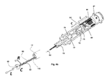
- FIGS. 4 a - b illustrate second drive mechanism 24 , which is actuated by interface 18 in greater detail.
- Drive mechanism 24 includes a housing 70 , which includes a neck region 72 and orientation wings 74 . Wings 74 engage respective slots in control unit 10 to prevent housing 70 from freely rotating.
- Housing 70 can be fabricated from two halves, which are attached via screws, snaps and the like.
- FIG. 4 b illustrates the internal components of drive mechanism 24 and the distal end of endoscope 12 showing shaft 82 of tool 80 protruding from distal opening 115 .
- the movements of components inside drive mechanism 24 are translated to movements of shaft 82 and grasper 83 as is indicated by R, L and C.
- An engagement element 76 is designed for holding a manual control end of a diagnostic or surgical tool 80 positionable through a working channel 13 of endoscope 12 .
- element 76 is configured for holding a loop-type finger hold 78 of a tool 80 having grasper 83 effector end ( FIG. 4 a ), while opening 77 is designed for holding a barrel-type finger hold 79 of tool 80 . Moving finger hold 78 with respect to finger hold 79 opens and closes jaws 83 of tool 80 .
- Tool 80 is positioned with holds 76 and 79 as shown in FIG. 4 b and shaft 82 positioned through a lumen in housing 70 and out from an opening at neck region 72 .
- Drive mechanism 24 is capable of 4 separate movements, rotating tool 80 (R) translating shaft 82 of tool 80 forwards and backwards 115 (L), and opening and closing the jaws of grasper 83 (C).
- drive mechanism 24 includes a motor 84 for driving a screw 86 into and out of a thread within cylinder 87 .
- screw 86 rotates into cylinder 87 thereby sliding finger hold 76 with respect to finger hold 79 (C).
- An additional motor can rotate cylinder 87 thereby rotating tool 80 within drive mechanism 24 .
- a tool 80 having control wires for steering a portion thereof can also be connected to drive mechanism 24 .
- the control wires of such a tool can be linked to one or more motors of drive mechanism 24 via, for example, gears and rods to enable the motor(s) to selectively pull one or more control wires and deflect a steerable portion of the tool.
- user interface 14 of the present invention enables simultaneous control over endoscope tip deflection and tool operation using a single hand.
- FIGS. 5 a - b describe user interface 14 in greater detail.
- User interface 14 includes a palm interface 16 which is able to pitch (P) and yaw (Y) simultaneously around axis 100 and 101 . These rotations are done relative to a ball joint/gimbal pivot point and a sensor mechanism (not shown), located at the top of base 102 .
- a hand (H) within interface 14 as is shown in FIG. 5 b with dorsum interface 17 supporting the back of the surgeon hand as described hereinabove.
- the resulting movement of the distal tip 118 of endoscope 12 is shown in FIG. 6 a .
- a home (neutral) position of palm interface 16 corresponds to a linear position (L) of distal tip 118
- pitch (P) and yaw (Y) of palm interface 16 results in tip 118 deflection as shown by arrows.
- Control over shaft 82 of tool 80 is effected via finger interface 18 .
- Pads 106 of interface 18 are used to control the opening and closing of the jaws. As is shown in FIG. 5 b , the index finger and thumb of the surgeon engage pads 106 allowing opening and closing of the jaws by pressing in and releasing pads 106 . Rotation of the jaws is controlled by rotating housing 108 around base 113 . Interface 18 allows the surgeon to simultaneously control both rotation of the jaws and their opening and closing using two fingers. Housing 108 can also be pulled out and pushed in relative to base 113 .
- a linear sensor located at base 113 of housing 108 allows the surgeon to control the distance the distal end of shaft 82 protrudes from the distal opening 115 ( FIG. 6 b ) of the working channel.
- the linear sensor may be simple micro switch with 3 contacts (forward backward and neutral) or may be any analog or digital sensor that measures linear travel.
- FIG. 6 b illustrates shaft rotation (R), grasper closing and opening (C) and shaft translation (L) of tool 80 in response to rotation of housing 108 , pressing in and releasing pads 106 and pushing pulling housing 108 (respectively).
- a prototype of the present control unit was fabricated and tested with a standard flexible endoscope.
- the prototype included a 3 D printed body housing a first drive mechanism for driving endoscope steering via a palm interface and a second drive mechanism for rotating and extending/retracting a grasper tool as well as actuating the jaws thereof.
- control unit was attached onto the endoscope and the resulting assembly ( FIG. 7 ) was bench tested for functionality including deflection of the endoscope tip, and actuation of a grasper tool positioned through the working channel of the endoscope.
Landscapes
- Health & Medical Sciences (AREA)
- Life Sciences & Earth Sciences (AREA)
- Surgery (AREA)
- Engineering & Computer Science (AREA)
- Veterinary Medicine (AREA)
- Public Health (AREA)
- General Health & Medical Sciences (AREA)
- Animal Behavior & Ethology (AREA)
- Biomedical Technology (AREA)
- Heart & Thoracic Surgery (AREA)
- Biophysics (AREA)
- Molecular Biology (AREA)
- Nuclear Medicine, Radiotherapy & Molecular Imaging (AREA)
- Medical Informatics (AREA)
- Physics & Mathematics (AREA)
- Radiology & Medical Imaging (AREA)
- Pathology (AREA)
- Optics & Photonics (AREA)
- Pulmonology (AREA)
- Anesthesiology (AREA)
- Hematology (AREA)
- Ophthalmology & Optometry (AREA)
- Mechanical Engineering (AREA)
- Endoscopes (AREA)
- Instruments For Viewing The Inside Of Hollow Bodies (AREA)
- Surgical Instruments (AREA)
Abstract
Description
- The present invention relates to a control unit that is attachable to a flexible endoscope and can be used to control both tip deflection and a working channel-positioned tool using a single hand.
- Flexible endoscopes (
FIG. 1 ) consist of a control head and a flexible shaft with a maneuverable tip. The head is connected to a light source via an ‘umbilical’ cord, through which pass other tubes transmitting air, water and suction, etc. The working channel is used for the passage of diagnostic or therapeutic tools. - Two side-by-side mounted rotatable knobs are mounted on the side of the control head and are used for up/down and right/left movement of the shaft tip.
- In experienced hands, these knobs can be used to control the angle of the tip in any direction, however, such control requires use of both hands rendering simultaneous control over any other instrument (e.g. diagnostic or therapeutic tool positioned through the working channel) impossible. To traverse this limitation, the control knobs of standard flexible endoscopes incorporate a friction braking system, so that the tip can be fixed temporarily in any desired position thus freeing the operator to control other instruments.
- Although such a solution enables control of a diagnostic or therapeutic tool positioned through a working channel when the endoscope tip is locked in a specific position, it does not enable endoscope tip repositioning while maintaining control over the tool. The latter is important in cases where a procedure requires maneuvering of an endoscope camera and tool simultaneously.
- In order to address this limitation of standard flexible endoscopes, the present inventor devised a control unit, which enables an operator to control the tip of a flexible endoscope as well as a tool positioned through the working channel thereof using a single hand.
- According to one aspect of the present invention, there is provided a control unit attachable to an endoscope having a shaft deflectable via two rotatable knobs, the control unit comprising: (a) a user interface including a first interface being mounted on a pivotal support attached to a housing of the control unit, the first interface being engageable by a palm of a hand; and (b) a drive unit operable via the user interface, the drive unit including a first drive mechanism for engaging the two rotatable knobs thereby allowing a user to control deflection of the shaft of the endoscope via the first interface.
- According to further features in preferred embodiments of the invention described below, a first rotatable knob of the two rotatable knobs controls up/down deflection of the shaft and a second rotatable knob of the two rotatable knobs controls left/right deflection of the shaft and further wherein the first interface controls both up/down and left/right deflection of the shaft.
- According to still further features in the described preferred embodiments, the first drive mechanism includes at least one motor operable via the first interface.
- According to still further features in the described preferred embodiments, the at least one motor operates the two knobs.
- According to still further features in the described preferred embodiments, the drive mechanism includes a set of gears interposed between the at least one motor and the two knobs.
- According to still further features in the described preferred embodiments, the drive unit further comprises a second drive mechanism for engaging a manually operable end of a surgical tool positionable through a working channel of the endoscope.
- According to still further features in the described preferred embodiments, the control unit further comprises a second interface being pivotally attached to the first interface and being engageable by one or more fingers of the hand, the second interface being for operating the surgical tool through the second drive mechanism.
- According to still further features in the described preferred embodiments, the control unit further comprises a restraint being pivotally attached to the first interface and having an element capable of elastically deforming to apply a restraining force to a back of the hand when the palm is engaged with the first interface.
- According to still further features in the described preferred embodiments, the pivotal support is gimbaled.
- According to still further features in the described preferred embodiments, the second interface includes pads simultaneously operable via thumb and index finger of the hand.
- According to still further features in the described preferred embodiments, the second drive mechanism includes a servo.
- According to still further features in the described preferred embodiments, the control unit further comprising a third interface for wirelessly controlling a remote device.
- According to still further features in the described preferred embodiments, the surgical tool includes a steerable shaft and an effector end controllable via the second interface.
- The present invention successfully addresses the shortcomings of the presently known configurations by providing a control unit for a flexible endoscope, which enables an operator to control the endoscope as well as a tool mounted therein via a single hand.
- Unless otherwise defined, all technical and/or scientific terms used herein have the same meaning as commonly understood by one of ordinary skill in the art to which the invention pertains. Although methods and materials similar or equivalent to those described herein can be used in the practice or testing of embodiments of the invention, exemplary methods and/or materials are described below. In case of conflict, the patent specification, including definitions, will control. In addition, the materials, methods, and examples are illustrative only and are not intended to be necessarily limiting.
- The invention is herein described, by way of example only, with reference to the accompanying drawings. With specific reference now to the drawings in detail, it is stressed that the particulars shown are by way of example and for purposes of illustrative discussion of the preferred embodiments of the present invention only, and are presented in the cause of providing what is believed to be the most useful and readily understood description of the principles and conceptual aspects of the invention. In this regard, no attempt is made to show structural details of the invention in more detail than is necessary for a fundamental understanding of the invention, the description taken with the drawings making apparent to those skilled in the art how the several forms of the invention may be embodied in practice.
- In the Drawings:
-
FIG. 1 is a prior art drawing of a standard flexible endoscope. -
FIGS. 2a-b illustrate the present control unit mounted on an endoscope (FIG. 2a ) and the interface and drive mechanism components of the control unit (FIG. 2b ). -
FIG. 3 illustrates the first drive mechanism for controlling the rotatable knobs of the endoscope. -
FIGS. 4a-b illustrate the second drive mechanism with attached tool. -
FIGS. 5a-b illustrate the various interfaces of the user interface of the present control unit (FIG. 5a ) and their engagement to a user's hand (FIG. 5b ). -
FIGS. 6a-b illustrate actuation of the endoscope tip (FIG. 6a ) and a working channel tool (FIG. 6b ) via the user interface. -
FIG. 7 is an image of a prototype control unit connected to a standard flexible endoscope. - The present invention is of a control unit which can be used to control the movement of a flexible endoscope tip, as well as the movement and function of a tool positioned through a working channel thereof.
- The principles and operation of the present invention may be better understood with reference to the drawings and accompanying descriptions.
- Before explaining at least one embodiment of the invention in detail, it is to be understood that the invention is not limited in its application to the details of construction and the arrangement of the components set forth in the following description or illustrated in the drawings. The invention is capable of other embodiments or of being practiced or carried out in various ways. Also, it is to be understood that the phraseology and terminology employed herein is for the purpose of description and should not be regarded as limiting.
- Endoscopic procedures require a surgeon to control both the endoscope and its associated tools (e.g. working channel tools). Since standard flexible endoscopes require both hands for tip deflection control, a surgeon cannot simultaneously control both endoscope and a surgical/therapeutic tool positioned through a working channel thereof.
- While reducing the present invention to practice, the present inventor devised a control unit which can be attached to a standard flexible endoscope and enable a surgeon to control both endoscope and a diagnostic/therapeutic tool (as well as other additional peripheral tools) using a single hand. As is further described herein, the control unit of the present invention can be retrofitted onto any flexible endoscope without modifications to the endoscope control head.
- Thus, according to one aspect of the present invention there is provided a control unit for a standard flexible endoscope. As used herein, the term “standard flexible endoscope” encompasses any endoscope with a deflectable tip controllable via rotatable knobs. Such an endoscope preferably includes a camera for imaging an anatomical region of interest.
- The control unit includes a drive unit with attached user interface. As is further described hereinunder, the interface is operated by a single hand of a user and actuates motors and gears/levers/wires within the control unit to thereby control the endoscope and diagnostic/therapeutic tool positioned therethrough.
- The user interface has separate controls for endoscope tip deflection and the diagnostic/therapeutic tool. The user interface includes a first interface which is mounted on a pivotal support (e.g. gimbaled) attached to a housing of the control unit. The first interface is engageable by a palm of a hand and enables the user to control deflection of the endoscope tip in any direction via a first drive mechanism of the drive unit.
- To maintain the palm of a user against the first interface through its operation, the control unit further includes a restraint, which forms a part of the first interface and includes an element that is capable of elastically deforming to apply a restraining force to a back of the hand (dorsum) when the palm is engaged with the first interface. When this restraint engages the back of the hand, the element elastically deforms and applies a downward force to the back of the hand thus maintaining the hand against the first interface and enabling precise control of this interface, as well as, enabling the user to pull up on the endoscope.
- The control unit also includes a second interface, which is pivotally attached to the first interface and is engageable by one or more fingers of the hand. The second interface controls the operation of a tool positioned through the working channel and attached to a second drive mechanism of the drive unit. The second interface can control an effector end of the tool (e.g., opening and closing a grasper), rotate or translate the shaft thereof and/or deflect a steerable portion thereof.
- The user interface of the present invention provides these three functions via movement of three separate limb joint and muscle groups:
- (i) The endoscope is moved up and down and side to side with respect to body by arm movement (primarily about the elbow and/or shoulder joints).
- (ii) The shaft of the endoscope is deflected via hand movement (primarily about the wrist joint). This is achieved by tilting the first interface.
- (iii) The working channel tool is actuated via finger movement (primarily about the inter-phalangeal joints and the metacarpal-phalangeal joints). Finger movement can be used to operate the effector end of the tool, translate and roll the shaft and/or deflect a steerable portion of the shaft.
- As is mentioned hereinabove, the control unit of the present invention engages the control knobs of the endoscope to thereby control deflection of the endoscope shaft via these knobs. Several approaches can be used to provide such functionality. For example, the user interface can be linked to the control knobs through a drive mechanism that includes gears, levers and/or wires which transfer the movement of the interface to rotation of the knob(s). The drive mechanism can be a simple mechanical ‘linkage’ or it can include one or motors/servos for enabling fine control as well as decreasing the interface force needed for knob rotation.
-
FIGS. 2a-6b illustrate one embodiment of the present control unit which is referred to herein ascontrol unit 10.Control unit 10 utilizes motors and servos for transferring user hand and finger movements at the interface to deflection of the endoscope shaft and operation of a tool provided through the working channel thereof. -
FIGS. 2a-b illustratecontrol unit 10 with attachedendoscope 12.Control unit 10 includes auser interface 14 which includes apalm interface 16,dorsum interface 17 and afinger interface 18.Interface 14 will be described in greater detail below.Control unit 10 also includes afirst drive mechanism 20 for translating movements ofpalm interface 16 to rotation ofknobs FIG. 2b ) ofendoscope 12.Drive mechanism 20 is an electro-mechanical device, which utilizes motors and gears to rotateknobs -
Control unit 10 further includes asecond drive mechanism 24 for transforming movements offinger interface 18 into operation of a tool provided through the working channel ofendoscope 12.Drive mechanism 24 is an electro-mechanical device that includes one or more motors/servos and gears to operate a manually operative end of a tool. -
User interface 14 can include additional interface elements including buttons and levers which enable wireless (WiFi, BT) control over peripheral instruments including a monitor (for displaying the endoscope camera image), a computer (for displaying files related to a procedure) or lighting. -
FIG. 2b illustratescontrol unit 10 with a portion of its housing removed to showgear cluster 30 andchip 32 that enablepalm interface 16 to control the rotation ofknobs 22. -
Chip 32 is electrically connected touser interface 14 and receives position sensor information therefrom. This information is then translated bychip 32 to command signals fordrive mechanisms Chip 32 can also be connected to external devices via wireless communication modes to enable a surgeon to control peripheral devices viainterface 14. -
FIG. 3 illustratesfirst drive mechanism 20 in greater detail.Gears 42 and 44 (also shown separately on right) have shapedholes 46 and 48 (respectively) to complement the shape ofknobs 22′ and 22 of endoscope 12 (respectively).Gear 42 is fixed around the wings ofknob 22 whilegear 44 is fixed aroundknob 22′. Aworm gear 50 is coupled togear 42; and aworm gear 52 is coupled togear 44. - A
gear 54 is fixed to ashaft 56 ofworm gear 50 and engages agear 60 driven bymotor 62.Gear 64 is fixed to a shaft 66 (shown detached therefrom for clarity) ofworm gear 52 and engagesgear 70 driven bymotor 72. - When chip 32 (
FIG. 2b ) detects a change in the orientation ofpalm interface 16, a signal is sent tomotors 62 and/or 72 to actuateknobs 22 and/or 22′ through the interconnecting gears. -
Knobs -
FIGS. 4a-b illustratesecond drive mechanism 24, which is actuated byinterface 18 in greater detail.Drive mechanism 24 includes ahousing 70, which includes aneck region 72 andorientation wings 74.Wings 74 engage respective slots incontrol unit 10 to preventhousing 70 from freely rotating.Housing 70 can be fabricated from two halves, which are attached via screws, snaps and the like. -
FIG. 4b illustrates the internal components ofdrive mechanism 24 and the distal end ofendoscope 12 showingshaft 82 oftool 80 protruding fromdistal opening 115. The movements of components insidedrive mechanism 24 are translated to movements ofshaft 82 andgrasper 83 as is indicated by R, L and C. - An
engagement element 76 is designed for holding a manual control end of a diagnostic orsurgical tool 80 positionable through a working channel 13 ofendoscope 12. In this embodiment,element 76 is configured for holding a loop-type finger hold 78 of atool 80 havinggrasper 83 effector end (FIG. 4a ), while opening 77 is designed for holding a barrel-type finger hold 79 oftool 80. Moving finger hold 78 with respect to finger hold 79 opens and closesjaws 83 oftool 80. -
Tool 80 is positioned with holds 76 and 79 as shown inFIG. 4b andshaft 82 positioned through a lumen inhousing 70 and out from an opening atneck region 72. -
Drive mechanism 24 is capable of 4 separate movements, rotating tool 80 (R) translatingshaft 82 oftool 80 forwards and backwards 115 (L), and opening and closing the jaws of grasper 83 (C). - To open and close the jaws of
grasper 83,drive mechanism 24 includes amotor 84 for driving ascrew 86 into and out of a thread withincylinder 87. When the shaft ofmotor 84 rotates, screw 86 rotates intocylinder 87 thereby sliding finger hold 76 with respect to finger hold 79 (C). - Forward and backward movement of cylinder 87 (L) moves
assembly 89 thus moving theentire tool 80 without actuatinggrasper 83. Such movement can be controlled bymotor 84 or another motor. - An additional motor can rotate
cylinder 87 thereby rotatingtool 80 withindrive mechanism 24. - A
tool 80 having control wires for steering a portion thereof can also be connected to drivemechanism 24. The control wires of such a tool can be linked to one or more motors ofdrive mechanism 24 via, for example, gears and rods to enable the motor(s) to selectively pull one or more control wires and deflect a steerable portion of the tool. - As is mentioned hereinabove,
user interface 14 of the present invention enables simultaneous control over endoscope tip deflection and tool operation using a single hand. -
FIGS. 5a-b describeuser interface 14 in greater detail.User interface 14 includes apalm interface 16 which is able to pitch (P) and yaw (Y) simultaneously aroundaxis base 102. In order to control the articulation seamlessly the surgeon places a hand (H) withininterface 14 as is shown inFIG. 5b withdorsum interface 17 supporting the back of the surgeon hand as described hereinabove. The resulting movement of thedistal tip 118 ofendoscope 12 is shown inFIG. 6a . A home (neutral) position ofpalm interface 16 corresponds to a linear position (L) ofdistal tip 118, while pitch (P) and yaw (Y) ofpalm interface 16 results intip 118 deflection as shown by arrows. - Control over
shaft 82 oftool 80 is effected viafinger interface 18.Pads 106 ofinterface 18 are used to control the opening and closing of the jaws. As is shown inFIG. 5b , the index finger and thumb of the surgeon engagepads 106 allowing opening and closing of the jaws by pressing in and releasingpads 106. Rotation of the jaws is controlled by rotatinghousing 108 aroundbase 113.Interface 18 allows the surgeon to simultaneously control both rotation of the jaws and their opening and closing using two fingers. Housing 108 can also be pulled out and pushed in relative tobase 113. A linear sensor located atbase 113 ofhousing 108 allows the surgeon to control the distance the distal end ofshaft 82 protrudes from the distal opening 115 (FIG. 6b ) of the working channel. The linear sensor may be simple micro switch with 3 contacts (forward backward and neutral) or may be any analog or digital sensor that measures linear travel. -
FIG. 6b illustrates shaft rotation (R), grasper closing and opening (C) and shaft translation (L) oftool 80 in response to rotation ofhousing 108, pressing in and releasingpads 106 and pushing pulling housing 108 (respectively). - As used herein the term “about” refers to ±10%.
- Additional objects, advantages, and novel features of the present invention will become apparent to one ordinarily skilled in the art upon examination of the following examples, which are not intended to be limiting.
- Reference is now made to the following example, which together with the above descriptions, illustrate the invention in a non limiting fashion.
- A prototype of the present control unit was fabricated and tested with a standard flexible endoscope. The prototype included a 3D printed body housing a first drive mechanism for driving endoscope steering via a palm interface and a second drive mechanism for rotating and extending/retracting a grasper tool as well as actuating the jaws thereof.
- The control unit was attached onto the endoscope and the resulting assembly (
FIG. 7 ) was bench tested for functionality including deflection of the endoscope tip, and actuation of a grasper tool positioned through the working channel of the endoscope. - The user reported smooth and effortless actuation of the endoscope shaft (deflection was tested at 360 degrees) as well as the grasper tool (shaft rotation, tool advancement and retraction and grasper jaw opening and closing). The user was capable of simultaneous deflection of the endoscope shaft and grasper tool actuation.
- It is appreciated that certain features of the invention, which are, for clarity, described in the context of separate embodiments, may also be provided in combination in a single embodiment. Conversely, various features of the invention, which are, for brevity, described in the context of a single embodiment, may also be provided separately or in any suitable subcombination.
- Although the invention has been described in conjunction with specific embodiments thereof, it is evident that many alternatives, modifications and variations will be apparent to those skilled in the art. Accordingly, it is intended to embrace all such alternatives, modifications and variations that fall within the spirit and broad scope of the appended claims. All publications, patents and patent applications mentioned in this specification are herein incorporated in their entirety by reference into the specification, to the same extent as if each individual publication, patent or patent application was specifically and individually indicated to be incorporated herein by reference. In addition, citation or identification of any reference in this application shall not be construed as an admission that such reference is available as prior art to the present invention.
Claims (13)
Priority Applications (1)
| Application Number | Priority Date | Filing Date | Title |
|---|---|---|---|
| US15/565,177 US10835108B2 (en) | 2015-08-11 | 2016-08-11 | Control unit for a flexible endoscope |
Applications Claiming Priority (3)
| Application Number | Priority Date | Filing Date | Title |
|---|---|---|---|
| US201562203421P | 2015-08-11 | 2015-08-11 | |
| US15/565,177 US10835108B2 (en) | 2015-08-11 | 2016-08-11 | Control unit for a flexible endoscope |
| PCT/IL2016/050879 WO2017025969A1 (en) | 2015-08-11 | 2016-08-11 | Control unit for a flexible endoscope |
Publications (2)
| Publication Number | Publication Date |
|---|---|
| US20180098687A1 true US20180098687A1 (en) | 2018-04-12 |
| US10835108B2 US10835108B2 (en) | 2020-11-17 |
Family
ID=57983566
Family Applications (1)
| Application Number | Title | Priority Date | Filing Date |
|---|---|---|---|
| US15/565,177 Active 2037-06-19 US10835108B2 (en) | 2015-08-11 | 2016-08-11 | Control unit for a flexible endoscope |
Country Status (13)
| Country | Link |
|---|---|
| US (1) | US10835108B2 (en) |
| EP (1) | EP3334323B1 (en) |
| JP (1) | JP6845809B2 (en) |
| KR (1) | KR102562929B1 (en) |
| CN (1) | CN107847105B (en) |
| AU (1) | AU2016306164A1 (en) |
| BR (1) | BR112017026204A2 (en) |
| CA (1) | CA2984729C (en) |
| DK (1) | DK3334323T3 (en) |
| ES (1) | ES2821101T3 (en) |
| IL (1) | IL255861A (en) |
| MX (1) | MX2017014628A (en) |
| WO (1) | WO2017025969A1 (en) |
Cited By (5)
| Publication number | Priority date | Publication date | Assignee | Title |
|---|---|---|---|---|
| DE102019201277A1 (en) | 2019-01-31 | 2020-08-06 | Deutsches Zentrum für Luft- und Raumfahrt e.V. | Device for guiding a medical flexible shaft |
| US20210186306A1 (en) * | 2018-09-07 | 2021-06-24 | Olympus Corporation | Manipulator system, and control method of manipulator system |
| WO2021171292A1 (en) * | 2020-02-26 | 2021-09-02 | Human Xtensions Ltd. | Control system for a colonoscope |
| US20220095892A1 (en) * | 2020-09-29 | 2022-03-31 | Boston Scientific Scimed, Inc. | Medical device controller |
| WO2025253295A1 (en) * | 2024-06-04 | 2025-12-11 | Multi-Scale Medical Robotics Center Limited | Handheld surgical system with one handed controller for simultaneous control of endoscope and robotic manipulator |
Families Citing this family (7)
| Publication number | Priority date | Publication date | Assignee | Title |
|---|---|---|---|---|
| BR112017026204A2 (en) | 2015-08-11 | 2018-09-04 | Human Xtensions Ltd. | control unit for a flexible endoscope. |
| IT201800004478A1 (en) * | 2018-04-13 | 2019-10-13 | CONTROL SYSTEM FOR MEDICAL DEVICE THAT CAN BE USED IN THE CONTEXT OF AN ENDOSCOPE. | |
| EP3793458B8 (en) | 2018-05-18 | 2024-09-25 | Vascular Technology, Incorporated | Articulating microsurgical instrument |
| WO2020144731A1 (en) * | 2019-01-07 | 2020-07-16 | オリンパス株式会社 | Endoscope |
| KR102793231B1 (en) * | 2019-11-18 | 2025-04-07 | 한국전기연구원 | Autonomous endoscope system |
| FR3103696B1 (en) * | 2019-12-03 | 2024-12-20 | Institut Hospitalo Univ De Chirurgie Mini Invasive Guidee Par Limage | Motorized actuation module of an endoscopic instrument |
| KR20250155580A (en) * | 2023-02-28 | 2025-10-30 | 보스톤 싸이엔티픽 싸이메드 인코포레이티드 | Medical systems, devices, and related methods for rotatably or pivotally coupling medical devices |
Citations (22)
| Publication number | Priority date | Publication date | Assignee | Title |
|---|---|---|---|---|
| US20070238927A1 (en) * | 2004-12-03 | 2007-10-11 | Olympus Corporation | Power driven bending endoscope with detachable insertion portion |
| US20080119696A1 (en) * | 2004-06-17 | 2008-05-22 | Hiroki Moriyama | Endoscope And Supportive Member For Bending Operation Of The Same |
| US20110065994A1 (en) * | 2009-03-18 | 2011-03-17 | Fujifilm Corporation | Endoscope |
| US20120130401A1 (en) * | 2009-07-31 | 2012-05-24 | Dexterite Surgical | Ergonomic and semi-automatic manipulator, and applications to instruments for minimally invasive surgery |
| WO2012127462A1 (en) * | 2011-03-22 | 2012-09-27 | Human Extensions Ltd. | Motorized surgical instruments |
| US20120277762A1 (en) * | 2011-04-29 | 2012-11-01 | Lathrop Ray A | Dexterous surgical manipulator and method of use |
| US8409080B2 (en) * | 2008-02-07 | 2013-04-02 | The Trustees Of Columbia University In The City Of New York | Remote endoscope handle manipulation |
| US8419623B2 (en) * | 2009-01-28 | 2013-04-16 | Cani Optical Systems, Llc | Portable endoscope for diverse medical disciplines |
| US20130190566A1 (en) * | 2011-06-16 | 2013-07-25 | Olympus Medical Systems Corp. | Endoscope |
| US8543240B2 (en) * | 2009-11-13 | 2013-09-24 | Intuitive Surgical Operations, Inc. | Master finger tracking device and method of use in a minimally invasive surgical system |
| US20130317522A1 (en) * | 2011-09-08 | 2013-11-28 | Olympus Medical Systems Corp. | Multi-degree-of-freedom forceps |
| US20150031953A1 (en) * | 2012-02-29 | 2015-01-29 | M.S.T. Medical Surgery Technologies Ltd. | Manual control system for maneuvering an endoscope |
| WO2015029041A1 (en) * | 2013-09-01 | 2015-03-05 | Human Extensions Ltd. | Control unit for a medical device |
| US20150148602A1 (en) * | 2013-11-22 | 2015-05-28 | Massachusetts Institute Of Technology | Steering techniques for surgical instruments |
| US20150359415A1 (en) * | 2013-05-17 | 2015-12-17 | Endochoice, Inc. | Endoscope Control Unit with Braking System |
| US20160089125A1 (en) * | 2014-09-30 | 2016-03-31 | Fujifilm Corporation | Endoscope apparatus |
| US20160166129A1 (en) * | 2014-12-15 | 2016-06-16 | GYRUS ACMI, INC., d/b/a Olympus Surgical Technologies America | Control of a basket retrieval device |
| US20160271385A1 (en) * | 2013-07-11 | 2016-09-22 | Transenterix Surgical, Inc. | Surgical instruments, systems, and methods for coupling of electrical energy to surgical instruments |
| US20170086651A1 (en) * | 2014-06-20 | 2017-03-30 | Olympus Corporation | Endoscope apparatus |
| US20170215697A1 (en) * | 2015-03-18 | 2017-08-03 | Olympus Corporation | Bending operation device and endoscope |
| US20170215705A1 (en) * | 2014-12-10 | 2017-08-03 | Olympus Corporation | Endoscopic system |
| US20170280973A1 (en) * | 2015-06-08 | 2017-10-05 | Olympus Corporation | Bending operation device and endoscope |
Family Cites Families (16)
| Publication number | Priority date | Publication date | Assignee | Title |
|---|---|---|---|---|
| JPS53873A (en) * | 1976-06-23 | 1978-01-07 | Mitsubishi Electric Corp | Fluid blowwout breaker |
| GB2070715A (en) | 1980-02-14 | 1981-09-09 | Welch Allyn Inc | Endoscope |
| JPH0255907A (en) | 1988-08-20 | 1990-02-26 | Juki Corp | Shape recognition device |
| JPH0642644Y2 (en) * | 1988-10-15 | 1994-11-09 | オリンパス光学工業株式会社 | Endoscopic bending device |
| JP3222190B2 (en) * | 1992-04-28 | 2001-10-22 | オリンパス光学工業株式会社 | Bending control device for endoscope |
| JPH1132977A (en) * | 1997-07-17 | 1999-02-09 | Olympus Optical Co Ltd | Endoscope system |
| US20020171625A1 (en) * | 2001-05-15 | 2002-11-21 | Jona Group, Ltd. | Pistol-grip trackball mouse |
| JP2003010112A (en) | 2001-06-28 | 2003-01-14 | Olympus Optical Co Ltd | Endoscope system |
| US20040059191A1 (en) * | 2002-06-17 | 2004-03-25 | Robert Krupa | Mechanical steering mechanism for borescopes, endoscopes, catheters, guide tubes, and working tools |
| CN100577085C (en) | 2004-12-03 | 2010-01-06 | 奥林巴斯株式会社 | Insertion part detachable electric curved endoscope |
| US7618413B2 (en) | 2005-06-22 | 2009-11-17 | Boston Scientific Scimed, Inc. | Medical device control system |
| JP4728075B2 (en) | 2005-09-28 | 2011-07-20 | オリンパスメディカルシステムズ株式会社 | Endoscope system |
| CN103228194B (en) | 2011-02-28 | 2015-11-25 | 奥林巴斯医疗株式会社 | Medical Devices with Curved Sections |
| US20140275763A1 (en) * | 2013-03-15 | 2014-09-18 | Lucent Medical Systems, Inc. | Partially disposable endoscopic device |
| WO2015038290A1 (en) | 2013-09-12 | 2015-03-19 | Endocon, Inc. | Power-assisted medical scope |
| BR112017026204A2 (en) | 2015-08-11 | 2018-09-04 | Human Xtensions Ltd. | control unit for a flexible endoscope. |
-
2016
- 2016-08-11 BR BR112017026204-5A patent/BR112017026204A2/en not_active Application Discontinuation
- 2016-08-11 ES ES16834773T patent/ES2821101T3/en active Active
- 2016-08-11 EP EP16834773.0A patent/EP3334323B1/en active Active
- 2016-08-11 AU AU2016306164A patent/AU2016306164A1/en not_active Abandoned
- 2016-08-11 CN CN201680029036.XA patent/CN107847105B/en active Active
- 2016-08-11 MX MX2017014628A patent/MX2017014628A/en unknown
- 2016-08-11 CA CA2984729A patent/CA2984729C/en active Active
- 2016-08-11 WO PCT/IL2016/050879 patent/WO2017025969A1/en not_active Ceased
- 2016-08-11 KR KR1020177035356A patent/KR102562929B1/en active Active
- 2016-08-11 JP JP2017560595A patent/JP6845809B2/en active Active
- 2016-08-11 US US15/565,177 patent/US10835108B2/en active Active
- 2016-08-11 DK DK16834773.0T patent/DK3334323T3/en active
-
2017
- 2017-11-22 IL IL255861A patent/IL255861A/en unknown
Patent Citations (24)
| Publication number | Priority date | Publication date | Assignee | Title |
|---|---|---|---|---|
| US20080119696A1 (en) * | 2004-06-17 | 2008-05-22 | Hiroki Moriyama | Endoscope And Supportive Member For Bending Operation Of The Same |
| US20070238927A1 (en) * | 2004-12-03 | 2007-10-11 | Olympus Corporation | Power driven bending endoscope with detachable insertion portion |
| US8409080B2 (en) * | 2008-02-07 | 2013-04-02 | The Trustees Of Columbia University In The City Of New York | Remote endoscope handle manipulation |
| US8419623B2 (en) * | 2009-01-28 | 2013-04-16 | Cani Optical Systems, Llc | Portable endoscope for diverse medical disciplines |
| US20110065994A1 (en) * | 2009-03-18 | 2011-03-17 | Fujifilm Corporation | Endoscope |
| US20120130401A1 (en) * | 2009-07-31 | 2012-05-24 | Dexterite Surgical | Ergonomic and semi-automatic manipulator, and applications to instruments for minimally invasive surgery |
| US8543240B2 (en) * | 2009-11-13 | 2013-09-24 | Intuitive Surgical Operations, Inc. | Master finger tracking device and method of use in a minimally invasive surgical system |
| WO2012127462A1 (en) * | 2011-03-22 | 2012-09-27 | Human Extensions Ltd. | Motorized surgical instruments |
| US20140025089A1 (en) * | 2011-03-22 | 2014-01-23 | Human Extensions Ltd. | Motorized surgical instruments |
| US9649096B2 (en) * | 2011-03-22 | 2017-05-16 | Human Extensions Ltd. | Motorized surgical instruments |
| US20120277762A1 (en) * | 2011-04-29 | 2012-11-01 | Lathrop Ray A | Dexterous surgical manipulator and method of use |
| US20130190566A1 (en) * | 2011-06-16 | 2013-07-25 | Olympus Medical Systems Corp. | Endoscope |
| US20130317522A1 (en) * | 2011-09-08 | 2013-11-28 | Olympus Medical Systems Corp. | Multi-degree-of-freedom forceps |
| US20150031953A1 (en) * | 2012-02-29 | 2015-01-29 | M.S.T. Medical Surgery Technologies Ltd. | Manual control system for maneuvering an endoscope |
| US20150359415A1 (en) * | 2013-05-17 | 2015-12-17 | Endochoice, Inc. | Endoscope Control Unit with Braking System |
| US20160271385A1 (en) * | 2013-07-11 | 2016-09-22 | Transenterix Surgical, Inc. | Surgical instruments, systems, and methods for coupling of electrical energy to surgical instruments |
| WO2015029041A1 (en) * | 2013-09-01 | 2015-03-05 | Human Extensions Ltd. | Control unit for a medical device |
| US20150148602A1 (en) * | 2013-11-22 | 2015-05-28 | Massachusetts Institute Of Technology | Steering techniques for surgical instruments |
| US20170086651A1 (en) * | 2014-06-20 | 2017-03-30 | Olympus Corporation | Endoscope apparatus |
| US20160089125A1 (en) * | 2014-09-30 | 2016-03-31 | Fujifilm Corporation | Endoscope apparatus |
| US20170215705A1 (en) * | 2014-12-10 | 2017-08-03 | Olympus Corporation | Endoscopic system |
| US20160166129A1 (en) * | 2014-12-15 | 2016-06-16 | GYRUS ACMI, INC., d/b/a Olympus Surgical Technologies America | Control of a basket retrieval device |
| US20170215697A1 (en) * | 2015-03-18 | 2017-08-03 | Olympus Corporation | Bending operation device and endoscope |
| US20170280973A1 (en) * | 2015-06-08 | 2017-10-05 | Olympus Corporation | Bending operation device and endoscope |
Cited By (11)
| Publication number | Priority date | Publication date | Assignee | Title |
|---|---|---|---|---|
| US20210186306A1 (en) * | 2018-09-07 | 2021-06-24 | Olympus Corporation | Manipulator system, and control method of manipulator system |
| US12121314B2 (en) * | 2018-09-07 | 2024-10-22 | Olympus Corporation | Manipulator system, and control method of manipulator system |
| DE102019201277A1 (en) | 2019-01-31 | 2020-08-06 | Deutsches Zentrum für Luft- und Raumfahrt e.V. | Device for guiding a medical flexible shaft |
| WO2021171292A1 (en) * | 2020-02-26 | 2021-09-02 | Human Xtensions Ltd. | Control system for a colonoscope |
| CN115334952A (en) * | 2020-02-26 | 2022-11-11 | 人类拓展有限公司 | Control system for colonoscope |
| EP4110160A4 (en) * | 2020-02-26 | 2024-03-27 | Human Xtensions Ltd. | CONTROL SYSTEM FOR A COLONOSCOPE |
| US12433474B2 (en) | 2020-02-26 | 2025-10-07 | Human Xtensions Ltd. | Control system for a colonoscope |
| US20220095892A1 (en) * | 2020-09-29 | 2022-03-31 | Boston Scientific Scimed, Inc. | Medical device controller |
| CN116322464A (en) * | 2020-09-29 | 2023-06-23 | 波士顿科学国际有限公司 | Medical Device Controller |
| US12178404B2 (en) * | 2020-09-29 | 2024-12-31 | Boston Scientific Scimed, Inc. | Medical device controller |
| WO2025253295A1 (en) * | 2024-06-04 | 2025-12-11 | Multi-Scale Medical Robotics Center Limited | Handheld surgical system with one handed controller for simultaneous control of endoscope and robotic manipulator |
Also Published As
| Publication number | Publication date |
|---|---|
| CN107847105A (en) | 2018-03-27 |
| CA2984729C (en) | 2024-02-27 |
| AU2016306164A1 (en) | 2017-11-30 |
| CA2984729A1 (en) | 2017-02-16 |
| DK3334323T3 (en) | 2020-09-28 |
| ES2821101T3 (en) | 2021-04-23 |
| EP3334323A1 (en) | 2018-06-20 |
| BR112017026204A2 (en) | 2018-09-04 |
| EP3334323A4 (en) | 2019-05-15 |
| JP2018526042A (en) | 2018-09-13 |
| US10835108B2 (en) | 2020-11-17 |
| EP3334323B1 (en) | 2020-06-24 |
| JP6845809B2 (en) | 2021-03-24 |
| KR102562929B1 (en) | 2023-08-03 |
| KR20180038417A (en) | 2018-04-16 |
| CN107847105B (en) | 2021-01-26 |
| MX2017014628A (en) | 2018-06-06 |
| IL255861A (en) | 2018-01-31 |
| WO2017025969A1 (en) | 2017-02-16 |
Similar Documents
| Publication | Publication Date | Title |
|---|---|---|
| US10835108B2 (en) | Control unit for a flexible endoscope | |
| US11020197B2 (en) | Control unit for a medical device | |
| US12295604B2 (en) | Control unit for a medical device | |
| US12433474B2 (en) | Control system for a colonoscope | |
| CN110312487A (en) | Controller for Surigical tool | |
| WO2012167043A2 (en) | Robotic systems, robotic system user interfaces, human interface devices for controlling robotic systems and methods of controlling robotic systems | |
| CN108882838B (en) | Endoscopic device and method | |
| CN107848106B (en) | Manipulator system | |
| HK1253926A1 (en) | Control unit attachable to an endoscope having a shaft deflectable via two rotatable knobs to allow one-handed operation of the knobs | |
| HK1253926B (en) | Control unit attachable to an endoscope having a shaft deflectable via two rotatable knobs to allow one-handed operation of the knobs | |
| CN120770937A (en) | Main control equipment capable of single-finger operation and main hand control console | |
| CA3016514C (en) | Control unit for a medical device | |
| HK40008022B (en) | Control unit for a medical device | |
| HK40008022A (en) | Control unit for a medical device | |
| HK1224538A1 (en) | Control unit for a medical device |
Legal Events
| Date | Code | Title | Description |
|---|---|---|---|
| FEPP | Fee payment procedure |
Free format text: ENTITY STATUS SET TO UNDISCOUNTED (ORIGINAL EVENT CODE: BIG.); ENTITY STATUS OF PATENT OWNER: SMALL ENTITY |
|
| FEPP | Fee payment procedure |
Free format text: ENTITY STATUS SET TO SMALL (ORIGINAL EVENT CODE: SMAL); ENTITY STATUS OF PATENT OWNER: SMALL ENTITY |
|
| AS | Assignment |
Owner name: HUMAN XTENSIONS LTD., ISRAEL Free format text: ASSIGNMENT OF ASSIGNORS INTEREST;ASSIGNOR:SHOLEV, MORDEHAI;REEL/FRAME:044310/0097 Effective date: 20171119 |
|
| STPP | Information on status: patent application and granting procedure in general |
Free format text: DOCKETED NEW CASE - READY FOR EXAMINATION |
|
| STPP | Information on status: patent application and granting procedure in general |
Free format text: NON FINAL ACTION MAILED |
|
| STPP | Information on status: patent application and granting procedure in general |
Free format text: RESPONSE TO NON-FINAL OFFICE ACTION ENTERED AND FORWARDED TO EXAMINER |
|
| STPP | Information on status: patent application and granting procedure in general |
Free format text: RESPONSE AFTER FINAL ACTION FORWARDED TO EXAMINER |
|
| STPP | Information on status: patent application and granting procedure in general |
Free format text: AWAITING TC RESP, ISSUE FEE PAYMENT VERIFIED |
|
| STCF | Information on status: patent grant |
Free format text: PATENTED CASE |
|
| MAFP | Maintenance fee payment |
Free format text: PAYMENT OF MAINTENANCE FEE, 4TH YR, SMALL ENTITY (ORIGINAL EVENT CODE: M2551); ENTITY STATUS OF PATENT OWNER: SMALL ENTITY Year of fee payment: 4 |
|
| AS | Assignment |
Owner name: HUMANTOUCH SURGICAL LTD, ISRAEL Free format text: ASSIGNMENT OF ASSIGNORS INTEREST;ASSIGNOR:HUMAN XTENSIONS LTD.;REEL/FRAME:072065/0560 Effective date: 20250728 |