EP3333685A1 - Berührungstafel-nasszustandserkennungsverfahren und kapazitive berührungsvorrichtung - Google Patents
Berührungstafel-nasszustandserkennungsverfahren und kapazitive berührungsvorrichtung Download PDFInfo
- Publication number
- EP3333685A1 EP3333685A1 EP16893797.7A EP16893797A EP3333685A1 EP 3333685 A1 EP3333685 A1 EP 3333685A1 EP 16893797 A EP16893797 A EP 16893797A EP 3333685 A1 EP3333685 A1 EP 3333685A1
- Authority
- EP
- European Patent Office
- Prior art keywords
- feature data
- coupling capacitor
- real
- wet state
- capacitor
- Prior art date
- Legal status (The legal status is an assumption and is not a legal conclusion. Google has not performed a legal analysis and makes no representation as to the accuracy of the status listed.)
- Ceased
Links
Images




Classifications
-
- G—PHYSICS
- G06—COMPUTING OR CALCULATING; COUNTING
- G06F—ELECTRIC DIGITAL DATA PROCESSING
- G06F3/00—Input arrangements for transferring data to be processed into a form capable of being handled by the computer; Output arrangements for transferring data from processing unit to output unit, e.g. interface arrangements
- G06F3/01—Input arrangements or combined input and output arrangements for interaction between user and computer
- G06F3/03—Arrangements for converting the position or the displacement of a member into a coded form
- G06F3/041—Digitisers, e.g. for touch screens or touch pads, characterised by the transducing means
- G06F3/0416—Control or interface arrangements specially adapted for digitisers
- G06F3/0418—Control or interface arrangements specially adapted for digitisers for error correction or compensation, e.g. based on parallax, calibration or alignment
-
- G—PHYSICS
- G06—COMPUTING OR CALCULATING; COUNTING
- G06F—ELECTRIC DIGITAL DATA PROCESSING
- G06F3/00—Input arrangements for transferring data to be processed into a form capable of being handled by the computer; Output arrangements for transferring data from processing unit to output unit, e.g. interface arrangements
- G06F3/01—Input arrangements or combined input and output arrangements for interaction between user and computer
- G06F3/03—Arrangements for converting the position or the displacement of a member into a coded form
- G06F3/041—Digitisers, e.g. for touch screens or touch pads, characterised by the transducing means
- G06F3/044—Digitisers, e.g. for touch screens or touch pads, characterised by the transducing means by capacitive means
-
- G—PHYSICS
- G06—COMPUTING OR CALCULATING; COUNTING
- G06F—ELECTRIC DIGITAL DATA PROCESSING
- G06F3/00—Input arrangements for transferring data to be processed into a form capable of being handled by the computer; Output arrangements for transferring data from processing unit to output unit, e.g. interface arrangements
- G06F3/01—Input arrangements or combined input and output arrangements for interaction between user and computer
- G06F3/03—Arrangements for converting the position or the displacement of a member into a coded form
- G06F3/041—Digitisers, e.g. for touch screens or touch pads, characterised by the transducing means
- G06F3/044—Digitisers, e.g. for touch screens or touch pads, characterised by the transducing means by capacitive means
- G06F3/0446—Digitisers, e.g. for touch screens or touch pads, characterised by the transducing means by capacitive means using a grid-like structure of electrodes in at least two directions, e.g. using row and column electrodes
Definitions
- Embodiments of the present invention relate to the field of touch technologies, and in particular, relate to a touch panel wet state detection method and a capacitive touch apparatus.
- the touch technology when applied to a smart terminal, enables a user to operate the terminal only by means of gesture operations. As such, a traditional mechanical keyboard is not necessary, such that man-machine interaction is simpler and more direct.
- the touch technology may be categorized based on the induction principle into: resistive touch technology, capacitive touch technology, surface acoustic wave touch technology, and optics touch technology. At present, the capacitive touch technology is most commonly used on the smart terminals.
- a capacity touch panel operates based on current induction of a human body.
- a finger of the user forms a coupling capacitor with a working surface, and a series of touch operation functions are implemented by detecting the capacitance value of the coupling capacitor.
- the capacitive touch technology may also be categorized into surface capacitive touch technology and projective capacitive touch technology.
- the projective capacitive touch technology is more widely used by the smart terminal manufacturers.
- upper and lower electrodes are refined to a matrix distribution, and are cross-distributed along the X axis and Y axis to form a capacitor matrix.
- capacitance variations at the touch position may be detected by scanning the X and Y axes, such that the touch position of the finger is calculated, and hence a series touch operation functions are implemented.
- the screen of the terminal may be wetted, such that all the functions of the touch operations are hard to be implemented or some damages may be caused to the terminal. Therefore, it is necessary to disenable all or a part of the touch functions to prevent misoperations caused by accidental touches, or close some power supplies in the circuit to prevent short circuit, for example, power supply of the USB.
- Objectives of embodiments of the present invention are to provide a touch panel wet state detection method and a capacitive touch apparatus, to at least solve the above problem in the prior art.
- embodiments of the present invention provide a touch panel wet state detection method.
- the method includes:
- the capacitive touch apparatus includes: a processor and a capacitor array network; wherein the processor is configured to acquire reference feature data obtained by statistical counting according to sample feature data output by a coupling capacitor when a medium between electrodes of each coupling capacitor in a capacitor array network is air; and acquire real-time feature data output by the coupling capacitor in the capacitor array network, and determine, according to the real-time feature data output by the coupling capacitor and the reference feature data, whether the coupling capacitor is in a wet state.
- reference feature data obtained by statistical counting of sample feature data output by a coupling capacitor when a medium between electrodes of each coupling capacitor in a capacitor array network is air is acquired; and real-time feature data output by the coupling capacitor in the capacitor array network is acquired, and whether the coupling capacitor is in a wet state is determined according to the real-time feature data output by the coupling capacitor and the corresponding reference feature data.
- the touch functions can be selectively adjusted, or a part of power supplies in the circuit can be closed.
- reference feature data counted according to sample feature data output by a coupling capacitor when a medium between electrodes of each coupling capacitor in a capacitor array network is air is acquired; and real-time feature data output by the coupling capacitor in the capacitor array network is acquired, and whether the corresponding coupling capacitor is in a wet state when flooded or immersed in the water is determined according to the real-time feature data output by the coupling capacitor and the corresponding reference feature data.
- the touch functions are selectively adjusted, or a part of power supplies in the circuit are closed.
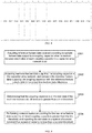
- FIG. 1 is a schematic flowchart of a wet state detection method according to Embodiment 1 of the present invention. As illustrated in FIG. 1 , the method includes the following steps:
- the capacitor array network of a touch panel may be formed of a driving electrode and a sensing electrode
- the coupling capacitor may refer to a capacitor node formed between the driving electrode and the sensing electrode.
- the feature data output by the coupling capacitor may become smaller. Accordingly, the capacitor array network is directly placed into water, and sample feature data output by the coupling capacitor is measured.
- the sample feature data reflects a capacitance value, which for example, may be a voltage signal output by the capacitor or a digitalization result of the voltage signal.
- the sample feature data is statistically collected to obtain the reference feature data.
- S102 acquiring real-time feature data output by the coupling capacitor in the capacitor array network, and determining whether the coupling capacitor is in a wet state according to the real-time feature data output by the coupling capacitor and the reference feature data.
- the real-time feature data output by the same coupling capacitor may become smaller. That is, in case of no touch, before the touch panel enters into the water, the feature data output by the coupling capacitor is the reference feature data, whereas after the touch panel enters into the water, the feature data output by the coupling capacitor may relatively becomes smaller. Therefore, in this embodiment, in step S102, a value of the real-time feature data is compared with a value of the reference feature data; and if the value of the real-time feature data is less than the value of the reference feature data, it is determined that the corresponding coupling capacitor is in the wet state.
- FIG. 2 is a schematic flowchart of a wet state detection method according to Embodiment 2 of the present invention. As illustrated in FIG. 2 , the method includes the following steps:
- the sample feature data output by the coupling capacitor may be acquired by directly placing the capacitor array network into water, and differences between the sample feature data output by the coupling capacitor and the corresponding reference feature data is calculated to obtain sample feature data differences. A statistical calculation is performed for these differences to determine the first threshold. For example, the first threshold is obtained by performing an average operation for the sample feature differences of all the coupling capacitors.
- Table 1 Data of real-time capacitance values of mutual-capacitors in an N x M capacitor array A00 A01 A02 A03 ... ... A0(M-3) A0(M-2) A0(M-1) A10 A11 A12 A13 ... ... A1(M-3) A1(M-2) A1(M-1) A20 A21 A22 A23 ...
- N x M mutual-capacitors there are N rows of driving detection channels and M rows of sensing detection channel, and thus N x M mutual-capacitors are formed.
- Data of real-time capacitance value of the N x M mutual-capacitors is A00 togetherA(N-1)(M-1) respectively.
- the data of these capacitance values may be regarded as the real-time feature data.
- Table 2 Data of real-time capacitance values of self-capacitors in an N x M capacitor array CX0 CX 1 CX 2 CX 3 ... ... CX (N-3) CX (N-2) CX (N-1) CY0 CY 1 CY 2 CY 3 ... ... CY (M-3) CY (M-2) CY (M-1)
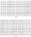
- FIG. 3 to FIG. 5 are tables of data of capacitance reference values, data of real-time capacitance values and data of capacitance differences respectively according to a specific example of a mutual-capacitor according to Embodiment 1 of the present invention.
- the real-time capacitance values output by the mutual-capacitors are partially abruptly reduced.
- the capacitance differences output by the mutual-capacitors not flooded with water are relatively smaller, which may be even ignored.
- the capacitance differences output by the mutual-capacitors flooded with water are relatively greater.
- the first threshold may be defined to 111, such that the wet state may be relatively accurately differentiated.
- the first threshold may be obtained by using the method as described in Embodiment 2, which is thus not described herein any further. It should be noted that, it is only required that the specific data in FIG. 3 to FIG. 5 reflects the capacitance values of the mutual-capacitors, which are related to the specific detection circuit, and are thus not described herein any further.
- FIG. 6 to FIG. 8 are tables of data of capacitance reference values, data of real-time capacitance values and data of capacitance differences according to a specific example of a self-capacitor according to Embodiment 1 of the present invention.
- the first threshold applicable to the situation of self-capacitor may be 2549.
- a wet region position may also be determined according to coordinates of the coupling capacitor in the wet state; and/or a total area of a wet region may be determined according the number of coupling capacitors in the wet state.
- FIG. 9 is a schematic flowchart of a wet state detection method according to Embodiment 3 of the present invention. As illustrated in FIG. 9 , the method may include the following steps:
- steps S301 to S303 may be referenced to the above embodiments, which are thus not described herein any further.
- S304 performing variance statistical counting for the real-time feature data differences output by different coupling capacitors greater than the first threshold, and reporting the wet state to a system of a smart terminal if an acquired variance is less than a second threshold.
- the variance of the variations of the capacitances of the coupling capacitors may be relatively smaller, that is, the variances of the feature data differences are smaller. Therefore, in this embodiment, using the method for statistically calculating the first threshold as described above, the second threshold may be calculated. The variances of the differences of the feature data are compared with the second threshold to further determine the wet state, and further report the wet state to the system.
- the system prevents misoperations by adjusting the touch operation function according to the specific circumstances of the wet state, for example, the total area of the wet region and the position of the wet region, or prevents damages caused to the terminal by further partially closing the power supply of the terminal.
- FIG. 10 is a schematic flowchart of a wet state detection method according to Embodiment 4 of the present invention. As illustrated in FIG. 10 , the method includes the following steps:
- steps S401 to S403 may be referenced to the above embodiments, which are thus not described herein any further.
- S404 reporting the wet state to a system of a smart terminal if the total area of the wet region is greater than a predetermined third threshold.
- the third threshold may be used as a judgment criterion for determining severity of the wet state
- a fourth threshold may be user-defined. If the total area of the wet region is less than the third threshold, it is determined that the current wet state may cause no impact to the terminal. If the total area of the wet region is greater than the third threshold, it is determined that the wet state may cause impacts to the terminal. In this case, the wet state is reported to the system of the smart terminal. The system prevents misoperations by adjusting the touch operation function according to the specific circumstances of the wet state, for example, the total area of the wet region and the position of the wet region, or prevents damages caused to the terminal by further partially closing the power supply of the terminal.
- FIG. 11 is a schematic flowchart of a wet state detection method according to Embodiment 5 of the present invention. As illustrated in FIG. 11 , the method includes the following steps:
- the sampling the real-time feature data output by the coupling capacitor in the capacitor array network for multiple times to generate the average real-time feature data corresponding to the coupling capacitor in step S502 may include: performing de-bounce for the real-time feature data acquired via sampling, and generating the average real-time feature data corresponding to the coupling capacitor according to the de-bounced real-time feature data.
- the sampling frequency for sampling the real-time feature data for multiple times is higher than a sampling frequency before the touch panel is wetted.
- the sampling frequency is improved by controlling a refresh frequency, and thus sampling accuracy of the real-time feature data is improved.
- S503 determining whether the coupling capacitor is in a wet state according to the average real-time feature data output by the coupling capacitor and reference feature data.
- the coupling capacitor is in the wet state if a value of the average real-time feature data is less than a value of the reference feature data.
- a wet region position is determined according to coordinates of the coupling capacitor in the wet state; and/or a total area of a wet region is determined according the number of coupling capacitors in the wet state.
- the average real-time feature data output by the coupling capacitor is compared with the corresponding reference feature data to determine a real-time feature data difference; and it is determined that the corresponding coupling capacitor is in the wet state if the real-time feature data difference is greater than the first threshold.
- the method further includes: performing variance statistical counting for the real-time feature data differences greater than the first threshold output by different coupling capacitors, and reporting the wet state to a system of a smart terminal if the variance is less than the second threshold.
- the wet state is reported to a system of a smart terminal if the total area of the wet region is greater than the third threshold.
- the capacitor array network is a self-capacitor array network, and the coupling capacitor is a self-capacitor; or the capacitor array network is a mutual-capacitor array network, and the coupling capacitor is a mutual-capacitor.
- FIG. 12 is a schematic structural diagram of a capacitive touch apparatus according to Embodiment 6 of the present invention.
- the capacitive touch apparatus includes: a processor 601 and a capacitor array network 602; wherein the processor is configured to acquire reference feature data counted according to sample feature data output by a coupling capacitor when a medium between electrodes of each coupling capacitor in a capacitor array network is air; and acquire real-time feature data output by the coupling capacitor in the capacitor array network, and determine whether the coupling capacitor is in a wet state according to the real-time feature data output by the coupling capacitor and a corresponding reference feature data.
- the processor 601 is further configured to determine that the corresponding coupling capacitor is in the wet state if a value of the real-time feature data is less than a value of the reference feature data.
- the processor is further configured to compare the real-time feature data output by the coupling capacitor with the corresponding reference feature data to determine a real-time feature data difference; and determine that the corresponding coupling capacitor is in the wet state if the real-time feature data difference is greater than a first threshold.
- the processor 601 is further configured to perform variance counting for the real-time feature data output by different coupling capacitor which is greater than the first threshold, and report the wet state to a system of a smart terminal if the acquired variance is less than a second threshold.
- the processor 601 is further configured to determine a wet region position according to coordinates of the coupling capacitor in the wet state; and/or determine a total area of a wet region according the number of coupling capacitors in the wet state.
- the processor 601 is further configured to report the wet state to a system of a smart terminal if the total area of the wet region is greater than a predetermined third threshold.
- the processor 601 is further configured to sample the real-time feature data output by the coupling capacitor in the capacitor array network for multiple times to generate average real-time feature data corresponding to the coupling capacitor, and determine, according to the average real-time feature data output by the coupling capacitor and the reference feature data, whether the corresponding coupling capacitor is in the wet state.
- the processor 601 is further configured to perform de-bouncing for the real-time feature data acquired via sampling, and generate the average real-time feature data corresponding to the coupling capacitor according to the de-bounced real-time feature data.
- the processor 601 is further configured to determine that the corresponding coupling capacitor is in the wet state if a value of the average real-time feature data is less than a value of the reference feature data.
- the processor 601 is further configured to compare the average real-time feature data output by the coupling capacitor with the corresponding reference feature data to determine an average real-time feature data difference; and determine that the corresponding coupling capacitor is in the wet state if the average real-time feature data difference is greater than the first threshold.
- the processor 601 is further configured to perform variance statistical calculation for the real-time feature data greater than the first threshold, and report the wet state to a system of a smart terminal if the acquired variance is less than the second threshold.
- FIG. 13 is a schematic structural diagram of a capacitive touch apparatus according to Embodiment 7 of the present invention.
- this embodiment takes the example where the coupling capacitors are mutual-capacitors as an example. That is, the capacitor array network is a mutual-capacitor array network.
- the capacitor array network includes: a driving channel 701, a sensing channel 702, a multiplexer 703, a controller 704, and a mutual-capacitor array network 705.
- the driving channel 701 is configured to provide a driving signal for the coupling capacitor.
- the sensing channel 702 is configured to receive an output signal from the coupling capacitor.
- the multiplexer 703 is configured to enable a plurality of coupling capacitors to multiplex the same driving channel 701 or the same sensing channel 702.
- the controller 704 is configured to acquire reference feature data obtained by statistical calculation or counting of sample feature data output by a coupling capacitor when a medium between electrodes of each coupling capacitor in the capacitor array network 705 is air; and acquire real-time feature data output by the coupling capacitor in the capacitor array network, and determine, according to the real-time feature data and the corresponding reference feature data, whether the coupling capacitor is in a wet state.
- controller 704 may be referenced to the related disclosure of the processor in the above embodiments, which is thus not described herein any further.
- the apparatus according to the embodiments of the present application may be practiced by a computer program.
- a person skilled in the art should understand the above division of units and modules is only an exemplary one, and if the apparatus is divided into other units or modules or not divided, the technical solution shall also fall within the protection scope of the present application as long as the information object has the above functions.
- the embodiments of the present application may be described to illustrate methods, apparatuses (devices), or computer program products. Therefore, hardware embodiments, software embodiments, or hardware-plus-software embodiments may be used to illustrate the present application.
- the present application may further employ a computer program product which may be implemented by at least one non-transitory computer-readable storage medium with an executable program code stored thereon.
- the non-transitory computer-readable storage medium comprises but not limited to a disk memory, a CD-ROM, and an optical memory.
- the present invention is described based on the flowcharts and/or block diagrams of the method, apparatus (device), and computer program product. It should be understood that each process and/or block in the flowcharts and/or block diagrams, and any combination of the processes and/or blocks in the flowcharts and/or block diagrams may be implemented using computer program instructions. These computer program instructions may be issued to a computer, a dedicated computer, an embedded processor, or processors of other programmable data processing device to generate a machine, which enables the computer or the processors of other programmable data processing devices to execute the instructions to implement an apparatus for implementing specific functions in at least one process in the flowcharts and/or at least one block in the block diagrams.
- These computer program instructions may also be stored a non-transitory computer-readable memory capable of causing a computer or other programmable data processing devices to work in a specific mode, such that the instructions stored on the non-transitory computer-readable memory implement a product comprising an instruction apparatus, where the instruction apparatus implements specific functions in at least one process in the flowcharts and/or at least one block in the block diagrams.
- These computer program instructions may also be stored on a computer or other programmable data processing devices, such that the computer or the other programmable data processing devices execute a series of operations or steps to implement processing of the computer.
- the instructions when executed on the computer or the other programmable data processing devices, implement the specific functions in at least one process in the flowcharts and/or at least one block in the block diagrams.
Landscapes
- Engineering & Computer Science (AREA)
- General Engineering & Computer Science (AREA)
- Theoretical Computer Science (AREA)
- Human Computer Interaction (AREA)
- Physics & Mathematics (AREA)
- General Physics & Mathematics (AREA)
- Position Input By Displaying (AREA)
- Investigating Or Analyzing Materials By The Use Of Electric Means (AREA)
- Examining Or Testing Airtightness (AREA)
Applications Claiming Priority (1)
| Application Number | Priority Date | Filing Date | Title |
|---|---|---|---|
| PCT/CN2016/103984 WO2018076332A1 (zh) | 2016-10-31 | 2016-10-31 | 触摸屏湿水状态检测方法及电容触控装置 |
Publications (2)
| Publication Number | Publication Date |
|---|---|
| EP3333685A1 true EP3333685A1 (de) | 2018-06-13 |
| EP3333685A4 EP3333685A4 (de) | 2018-08-08 |
Family
ID=62021427
Family Applications (1)
| Application Number | Title | Priority Date | Filing Date |
|---|---|---|---|
| EP16893797.7A Ceased EP3333685A4 (de) | 2016-10-31 | 2016-10-31 | Berührungstafel-nasszustandserkennungsverfahren und kapazitive berührungsvorrichtung |
Country Status (5)
| Country | Link |
|---|---|
| US (1) | US10345976B2 (de) |
| EP (1) | EP3333685A4 (de) |
| KR (1) | KR101963995B1 (de) |
| CN (1) | CN108271418B (de) |
| WO (1) | WO2018076332A1 (de) |
Families Citing this family (11)
| Publication number | Priority date | Publication date | Assignee | Title |
|---|---|---|---|---|
| CN110596761A (zh) * | 2018-06-12 | 2019-12-20 | 义隆电子股份有限公司 | 电容式触控面板的液体检测方法及控制器 |
| CN109614016B (zh) * | 2019-01-11 | 2022-05-03 | 中国联合网络通信集团有限公司 | 电容触摸屏的触摸识别方法、装置及电子设备 |
| CN110460723B (zh) * | 2019-08-01 | 2020-11-27 | 珠海格力电器股份有限公司 | 屏幕保护方法、装置、计算机设备和计算机可读存储介质 |
| WO2021060619A1 (en) * | 2019-09-27 | 2021-04-01 | Samsung Electronics Co., Ltd. | Method and system for controlling access of data item |
| CN111143166B (zh) * | 2019-12-24 | 2024-04-23 | 维沃移动通信有限公司 | 一种电子设备及入水检测方法 |
| CN111578439A (zh) * | 2020-05-27 | 2020-08-25 | 珠海格力电器股份有限公司 | 触摸按键的湿手检测装置、线控器及空调 |
| CN115963937A (zh) * | 2021-10-09 | 2023-04-14 | 北京小米移动软件有限公司 | 口袋模式识别方法、装置、电子设备和存储介质 |
| CN116359295B (zh) * | 2021-12-27 | 2026-02-13 | 北京小米移动软件有限公司 | 终端溺水处理方法、装置及可读存储介质 |
| EP4407417A4 (de) | 2022-01-26 | 2025-03-05 | Samsung Electronics Co., Ltd. | Drahtlose stromübertragungsvorrichtung mit benutzerschnittstelle und verfahren zur bestimmung, ob eine berührungseingabe einer drahtlosen stromübertragungsvorrichtung auftritt |
| EP4668073A1 (de) | 2023-04-12 | 2025-12-24 | Samsung Electronics Co., Ltd. | Elektronische vorrichtung zur erfassung des kontakts mit einer flüssigkeit über einen berührungssensor |
| CN120103997B (zh) * | 2023-11-29 | 2026-01-30 | 荣耀终端股份有限公司 | 触控方法、触控面板及电子设备 |
Family Cites Families (11)
| Publication number | Priority date | Publication date | Assignee | Title |
|---|---|---|---|---|
| JPH08123618A (ja) * | 1994-10-21 | 1996-05-17 | Hitachi Ltd | 座標入力装置の座標データ採取方法 |
| JP4994489B2 (ja) * | 2010-10-19 | 2012-08-08 | パナソニック株式会社 | タッチパネル装置 |
| US8976146B2 (en) * | 2012-04-23 | 2015-03-10 | Silicon Integrated Systems Corp. | Method of reducing computation of water tolerance by projecting touch data |
| US9134866B2 (en) * | 2013-07-18 | 2015-09-15 | Sony Corporation | Dry/wet touch screen |
| EP3065035B1 (de) * | 2013-11-25 | 2018-11-14 | Huawei Device (Dongguan) Co., Ltd. | Informationsverarbeitungsverfahren und elektronische vorrichtung |
| US9310934B2 (en) * | 2014-02-21 | 2016-04-12 | Qualcomm Incorporated | Systems and methods of moisture detection and false touch rejection on touch screen devices |
| WO2015199602A1 (en) * | 2014-06-27 | 2015-12-30 | Flatfrog Laboratories Ab | Detection of surface contamination |
| US20160148402A1 (en) * | 2014-11-21 | 2016-05-26 | Kobo Incorporated | Method and system for extraneous object notification interface in mobile device operation |
| CN104391616B (zh) * | 2014-11-27 | 2017-03-22 | 上海天马微电子有限公司 | 一种触摸屏的像素点电容值检测范围的获取方法和装置 |
| US10437384B2 (en) * | 2015-03-13 | 2019-10-08 | Parade Technologies, Ltd. | Water detection and wipe detection algorithms for touchscreen proximity sensing |
| JP6250585B2 (ja) * | 2015-04-16 | 2017-12-20 | 株式会社東海理化電機製作所 | 操作検出装置 |
-
2016
- 2016-10-31 KR KR1020177026725A patent/KR101963995B1/ko not_active Expired - Fee Related
- 2016-10-31 CN CN201680001181.7A patent/CN108271418B/zh active Active
- 2016-10-31 EP EP16893797.7A patent/EP3333685A4/de not_active Ceased
- 2016-10-31 WO PCT/CN2016/103984 patent/WO2018076332A1/zh not_active Ceased
-
2017
- 2017-09-19 US US15/709,443 patent/US10345976B2/en active Active
Also Published As
| Publication number | Publication date |
|---|---|
| EP3333685A4 (de) | 2018-08-08 |
| CN108271418A (zh) | 2018-07-10 |
| CN108271418B (zh) | 2021-03-19 |
| WO2018076332A1 (zh) | 2018-05-03 |
| KR101963995B1 (ko) | 2019-03-29 |
| US10345976B2 (en) | 2019-07-09 |
| US20180120972A1 (en) | 2018-05-03 |
| KR20180053597A (ko) | 2018-05-23 |
Similar Documents
| Publication | Publication Date | Title |
|---|---|---|
| EP3333685A1 (de) | Berührungstafel-nasszustandserkennungsverfahren und kapazitive berührungsvorrichtung | |
| KR101446221B1 (ko) | 투사 정전용량식 터치 패널 스캐닝 방법, 기억 매체, 및 투사 정전용량식 터치 패널 스캐닝 장치 | |
| CN103995627B (zh) | 一种电容触摸屏的检测方法及装置 | |
| US20130342497A1 (en) | Detection method, device and system for detecting self-capacitance touch screen | |
| US10712870B2 (en) | Method for improving fault tolerance of touchscreen and touchscreen terminal | |
| US8866778B2 (en) | Method of detecting floating mode of a touch panel | |
| US9501180B2 (en) | Capacitance sensing apparatus and control method | |
| CN103365510A (zh) | 藉由投影触控数据减少排除手掌误触计算的方法 | |
| JP7225516B2 (ja) | データ検出方法および装置、記憶媒体、タッチ装置 | |
| US20180173366A1 (en) | Apparatus and method for capacitance calibration, and touch display screen | |
| US20200387258A1 (en) | Input device, input method and program | |
| CN108762653B (zh) | 触碰定位方法、装置及电子设备 | |
| US20230289012A1 (en) | Systems, methods, and devices for defect detection in capacitive touch panels | |
| US20130162593A1 (en) | Projected capacitive touch panel and coordinate detecting method thereof | |
| TWI613575B (zh) | 掃描信號頻率決定方法與偵測方法 | |
| US10031633B2 (en) | Touch panel device and method for controlling touch panel device | |
| EP3534238B1 (de) | Verfahren zur handhaltungserkennung, kapazitive berührungsvorrichtung und elektronische vorrichtung | |
| US20180307359A1 (en) | Touch determining device and method, and display device | |
| US9063626B2 (en) | Touch recognition method, touch key structure and touch device | |
| US10444903B2 (en) | Touch detection method | |
| US20160378262A1 (en) | Detection Method, Device And System For Detecting Self-Capacitance Touch Screen | |
| TW201401155A (zh) | 操作裝置 | |
| TW201640291A (zh) | 可攜式電子裝置及其觸控感測晶片與控制方法 | |
| EP4383051A1 (de) | Verfahren und vorrichtung zur bestimmung einer berührungssteuerungsposition und elektronische vorrichtung |
Legal Events
| Date | Code | Title | Description |
|---|---|---|---|
| PUAI | Public reference made under article 153(3) epc to a published international application that has entered the european phase |
Free format text: ORIGINAL CODE: 0009012 |
|
| 17P | Request for examination filed |
Effective date: 20170919 |
|
| AK | Designated contracting states |
Kind code of ref document: A1 Designated state(s): AL AT BE BG CH CY CZ DE DK EE ES FI FR GB GR HR HU IE IS IT LI LT LU LV MC MK MT NL NO PL PT RO RS SE SI SK SM TR |
|
| AX | Request for extension of the european patent |
Extension state: BA ME |
|
| RIN1 | Information on inventor provided before grant (corrected) |
Inventor name: WU, SHUANG Inventor name: FANG, JUN |
|
| A4 | Supplementary search report drawn up and despatched |
Effective date: 20180711 |
|
| RIC1 | Information provided on ipc code assigned before grant |
Ipc: G06F 3/044 20060101ALI20180705BHEP Ipc: G06F 3/041 20060101AFI20180705BHEP |
|
| 17Q | First examination report despatched |
Effective date: 20190621 |
|
| DAV | Request for validation of the european patent (deleted) | ||
| DAX | Request for extension of the european patent (deleted) | ||
| REG | Reference to a national code |
Ref country code: DE Ref legal event code: R003 |
|
| STAA | Information on the status of an ep patent application or granted ep patent |
Free format text: STATUS: THE APPLICATION HAS BEEN REFUSED |
|
| 18R | Application refused |
Effective date: 20200607 |