EP3333343B1 - Filterklappe für automatische poolroboter - Google Patents
Filterklappe für automatische poolroboter Download PDFInfo
- Publication number
- EP3333343B1 EP3333343B1 EP17205988.3A EP17205988A EP3333343B1 EP 3333343 B1 EP3333343 B1 EP 3333343B1 EP 17205988 A EP17205988 A EP 17205988A EP 3333343 B1 EP3333343 B1 EP 3333343B1
- Authority
- EP
- European Patent Office
- Prior art keywords
- filter
- door
- intake port
- debris
- closed position
- Prior art date
- Legal status (The legal status is an assumption and is not a legal conclusion. Google has not performed a legal analysis and makes no representation as to the accuracy of the status listed.)
- Active
Links
Images


Classifications
-
- E—FIXED CONSTRUCTIONS
- E04—BUILDING
- E04H—BUILDINGS OR LIKE STRUCTURES FOR PARTICULAR PURPOSES; SWIMMING OR SPLASH BATHS OR POOLS; MASTS; FENCING; TENTS OR CANOPIES, IN GENERAL
- E04H4/00—Swimming or splash baths or pools
- E04H4/14—Parts, details or accessories not otherwise provided for
- E04H4/16—Parts, details or accessories not otherwise provided for specially adapted for cleaning
- E04H4/1654—Self-propelled cleaners
-
- C—CHEMISTRY; METALLURGY
- C02—TREATMENT OF WATER, WASTE WATER, SEWAGE, OR SLUDGE
- C02F—TREATMENT OF WATER, WASTE WATER, SEWAGE, OR SLUDGE
- C02F1/00—Treatment of water, waste water, or sewage
- C02F1/001—Processes for the treatment of water whereby the filtration technique is of importance
-
- E—FIXED CONSTRUCTIONS
- E04—BUILDING
- E04H—BUILDINGS OR LIKE STRUCTURES FOR PARTICULAR PURPOSES; SWIMMING OR SPLASH BATHS OR POOLS; MASTS; FENCING; TENTS OR CANOPIES, IN GENERAL
- E04H4/00—Swimming or splash baths or pools
- E04H4/14—Parts, details or accessories not otherwise provided for
- E04H4/16—Parts, details or accessories not otherwise provided for specially adapted for cleaning
-
- E—FIXED CONSTRUCTIONS
- E04—BUILDING
- E04H—BUILDINGS OR LIKE STRUCTURES FOR PARTICULAR PURPOSES; SWIMMING OR SPLASH BATHS OR POOLS; MASTS; FENCING; TENTS OR CANOPIES, IN GENERAL
- E04H4/00—Swimming or splash baths or pools
- E04H4/14—Parts, details or accessories not otherwise provided for
- E04H4/16—Parts, details or accessories not otherwise provided for specially adapted for cleaning
- E04H4/1618—Hand-held powered cleaners
- E04H4/1636—Suction cleaners
-
- C—CHEMISTRY; METALLURGY
- C02—TREATMENT OF WATER, WASTE WATER, SEWAGE, OR SLUDGE
- C02F—TREATMENT OF WATER, WASTE WATER, SEWAGE, OR SLUDGE
- C02F2103/00—Nature of the water, waste water, sewage or sludge to be treated
- C02F2103/42—Nature of the water, waste water, sewage or sludge to be treated from bathing facilities, e.g. swimming pools
Definitions
- the present invention relates to the field of swimming pool cleaners and, in particular, to a filter door for a filter included in a swimming pool cleaner, such as a robotic and/or motorized pool cleaner.
- motorized pool cleaners In order to automate pool cleaning, many motorized or automatic pool cleaners have been developed. There are many different types of swimming pool cleaners; however, typically, motorized pool cleaners (which are sometimes also referred to as pool cleaning robots) use a pump or suction system to clean a pool.
- the pump or suction system draws a combination of water and dirt/debris, via an intake, into a filter included or installed in the pool cleaner, such as a filter bag or filter box, that is configured to capture the dirt/debris, thereby cleaning the pool water.
- a pool cleaning robot may include cleaning brushes or pressurized jets to dislodge debris from pool surfaces so that the dislodged dirt/debris can be drawn into the filter (via the intake) by the suction of the pump system.
- U.S. Patent No. 8,434,182 discloses an autonomous pool cleaner with high pressure cleaning jets that dislodge dirt/debris from pool surfaces so that the dirt/debris can be drawn into and captured in a filter bag (due to suction created by a pump system).
- US 4,768,532 A discloses a low profile carriage is mounted on widely spread wheels to roll along the underwater surfaces of a swimming pool.
- the carriage is propelled by a high velocity stream of water projecting from a rearwardly directed thrust nozzle.
- the water so drawn in passes through a screen, trapping the debris in a removable pod or bin depending from the carriage.
- the top of the carriage is relatively flat and the depending debris pod is curved downward to form an inverted air foil, whereby the pressure differential between the top and bottom of the carriage biases the carriage against the swimming pool surface traversed thereby.
- US 5,337,434 A relates to directional control means which are provided for robotic swimming pool or water tank cleaner of the type having an internal filter bag for removing and retaining debris from the pool, an electric pump for drawing water through the filter bag and two parallel motor driven cylindrical brushes for propelling the cleaner along and sweeping the bottom surface of the pool, said control means including one or more water activated hydraulic cylinders located on the side of the cleaner between the brushes, each containing a leg adapted to project downwardly to contact the pool bottom and partially lift one side of the cleaner. As the cleaner moves along the pool bottom it pivots around the projected leg to change direction. Manual or automatic means can be provided to activate the hydraulic legs.
- EP 2 186 970 A2 discloses a pool cleaning vehicle.
- the vehicle includes a housing, a bottom frame (20) and a filter bag between the housing the bottom frame (20) and attached to the bottom frame (20).
- the vehicle includes an intake (22) and an outlet, both of which are in communication with the filter bag.
- the housing is releaseably attached to the bottom frame and the filter bag releaseably connected to the bottom frame (20).
- a V-shaped self locking clip (40) with normally outwardly extending legs (42,44) serves as the attachment member and when urged toward each other with the housing in the locked position allows for easy release.
- At least one of the intake (22) or outlet includes a filter member (32).
- the filter member (32) includes a means for attachment and a particulate filter member for filtering particulates from the water.
- the filter member (32) is attached to the vehicle at or proximate to the perimeter of the intake (22) or outlet.
- a filter for a pool cleaner includes an intake port or mount configured to be installed or placed over the intake port of an autonomous robot.
- the intake port of the filter or the robot may include a flap (also called a "filter door") that is configured to selectively cover the respective intake port.
- the flap may be opened as the pump system initiates suction so that pool water and there debris therein can enter the filter. Then, when the pump system is turned off and/or before the pool cleaner is removed from the pool, the flap may close the intake port to prevent debris from exiting the filter.
- the cover is often pivotally coupled to the filter box or filter bag (or the robot).
- the pivotal coupling leaves at least a small gap between the body of the filter (or the robot) and the flap; this gap allows for rotation of the flap with respect to the filter (or robot). Consequently, collected debris may escape back into the pool via the gap. Additionally or alternatively, dirt and debris may gather in the gap, thereby preventing or inhibiting the flap from rotating to a closed position. Additionally, dirt and debris that gathers in the gap may wear the edge of the flap (which is often formed from a plastic material) as the flap opens and closes. For example, sand, which is very abrasive, could collect in the gap between the body of the filter (or the robot) and the flap and prematurely wear the body or the flap in this gap area as the flap repeatedly opens and closes.
- the flap is attached to the filter box/bag (or robot) via a spring-biased hinge (or other such rotational coupling).
- the spring since the spring is regularly submerged in a body of water, the spring may lose its resiliency and/or corrode. Then, the flap may not close properly and debris may escape the filter and/or robot and re-enter the pool, rendering the pool cleaning robot largely useless (since the cleaner will simply be relocating dirt and debris within a pool).
- a filter and/or pool cleaning robot may include filtered outlets (e.g., sieves) configured to drain the water from filter bag or filter box while limiting the amount of debris that can exit the filter bag or box during this draining. Draining the filter bag or filter box may lighten the filter, reducing the overall weight of the autonomous robot so that a user can easily remove the autonomous robot from a pool.
- filtered outlets e.g., sieves
- Draining the filter bag or filter box may lighten the filter, reducing the overall weight of the autonomous robot so that a user can easily remove the autonomous robot from a pool.
- these additional outlets may increase the complexity, and thus, the cost of the filters and/or robots.
- each additional outlet added to a filter and/or robot increases the chance of debris exiting the filter and dispersing back into the pool.
- an enhanced filter door that prevents debris from escaping a filter and/or better filters the escaping water without generating maintenance issues is desirable. Moreover, an enhanced filter door that increases drainage flow from the filter and/or robot (e.g., during removal of an autonomous pool cleaner in which the filter is installed from a pool) is desirable.
- the present invention relates to an enhanced filter door.
- the filter door includes a living hinge that biases the door to a closed position, eliminating the need for a spring or other such biasing member that might become corroded and/or ineffective after repeated underwater use.
- the filter door may also include mesh that allows water, but not debris, to exit therethrough.
- the mesh extends beyond the periphery of the filter door, over a pivot edge of a panel of the filter door to prevent dirt and debris from escaping around the pivot edge or becoming lodged therein.
- the portion of the mesh extending over the pivoting edge may acts as the living hinge.
- the present invention avoids problems created by known filter doors/covers/flaps (e.g., allowing dirt/debris to escape and malfunctioning due to a build-up of dirt in a gap adjacent a pivot edge of the door and/or issues associated with spring biasing). Consequently, a pool cleaner using a filter with the filter door presented herein may operate for a longer period of time without filter-door related maintenance (as compared to pool cleaners using filters with typical filter doors/covers).
- a pool cleaner using a filter with the filter door presented herein limits the amount of collected debris spilled back into the pool (through or around the filter door)
- the host pool cleaner may more effectively and efficiently clean a pool. More efficient cleaning may, in turn, reduce the amount of run time required for a pool cleaning robot, thereby extending the life span of other parts or components (e.g., the drive system) of the pool cleaning robot and reducing the costs of operation and maintenance for an end-user.
- the filter door may decrease or minimize the number of drains required to be included in the filter box and/or robot, thereby decreasing the complexity (and the cost) of a filter and/or robot. This minimization may also limit the number of parts or pieces that might malfunction, thereby decreasing frustration and maintenance costs for an end-user.
- the present invention relates to a filter door for an intake port of a filter for a swimming pool cleaner, comprising: a support structure with a pivot edge and a distal edge that rotates about the pivot edge in order to selectively move the support structure between a closed position that closes the intake port and an open position that opens the intake port; a mesh attached onto a surface of the support structure; and a living hinge that biases the filter door to the closed position.
- the present invention also relates to an autonomous swimming pool cleaner, comprising: a chassis defining an intake port; a filter that is removably positionable over the intake port, the filter including a door that comprises: a pivot edge and a distal edge that rotates about the pivot edge in order to selectively move the door between a closed position that closes the intake port and an open position that opens the intake port; and a mesh attached onto a surface extending between the pivot edge and the distal edge, the mesh providing a living hinge that biases the door to the closed position.
- an autonomous swing pool cleaner comprising a chassis defining an intake port; a filter that is removably positionable over the intake part, the filter comprising a filter door according to the present invention.
- the filter door and the pool cleaner may be further improved by the following additional features, which are independent of each other and may be freely and independently combined.
- the open position may allow ingress of fluid and debris into the filter and the closed position blocks passage of debris through the intake port while allowing fluid to flow therethrough.
- the support structure may extend across the intake port when the support structure is in the closed position.
- the mesh may be a mesh panel.
- the mesh or mesh panel may comprise an extension that extends beyond a periphery of the support structure.
- the extension may extend beyond the pivot edge to prevent debris from exiting the filter around the pivot edge when the support structure is in the open position, the closed position, and positions therebetween.
- the pivot edge may be disposed in a gap to allow rotation of the support structure with respect to the intake port and the extension prevents debris from entering the gap.
- the extension may provide the living hinge that biases the filter door to the closed position.
- the extension may comprise: a frame member that extends along a distal edge of the extension; and a flexible section disposed between the frame member and the support structure, wherein the flexible section provides the living hinge.
- the support structure may define drainage openings and the mesh spans the drainage openings.
- the filter door may not include a biasing member.
- the filter may be in fluid communication with the intake port and the door is configured to control a flow of debris between the filter and the intake port.
- the autonomous swimming pool cleaner may further comprise: a pump system configured to draw water and debris into the filter via the intake port, wherein, in the open position, the door allows the water and debris to enter the filter via the intake port and, in the closed position, the door retains the debris in the filter while allowing the water to exit the filter.
- a pump system configured to draw water and debris into the filter via the intake port, wherein, in the open position, the door allows the water and debris to enter the filter via the intake port and, in the closed position, the door retains the debris in the filter while allowing the water to exit the filter.
- the living hinge may bias the door to the closed position when pressure from the water and debris drawn into the intake port is below a pressure threshold.
- the mesh may comprise an extension that extends beyond a periphery of the surface.
- the filter door for an autonomous pool cleaner presented herein includes a living hinge that biases the door to a closed position and a mesh that covers openings in the door. Consequently, the openings allow water, but not dirt and debris to pass therethrough when the door is in a closed position.
- the mesh acts a sieve that allows for drainage.
- the mesh that extends beyond the periphery of a panel, which may be formed by overmolding (for example, by overmolding the panel onto the mesh) or other attachment methods, prevents dirt and debris from escaping around a pivot edge of the panel and also creates the living hinge.
- the living hinge may be formed in any manner with any material (e.g., plastic extensions may extend beyond a periphery of the panel).
- Other pool cleaners and or filters may also include filter doors; however, typically, the filter doors are biased by a spring or other such mechanism that may corrode or malfunction over time. Moreover, other filter doors typically allow dirt and debris to pass through and/or enter a gap that allows the filter door to rotate or pivot. This allows dirt and debris back into the pool (which then necessitates additional cleaning) and/or allows dirt and debris to build up in the gap. As referenced above, over time, this build-up may cause the filter door to malfunction, be damaged, and possibly rendering the filter door useless. By comparison, the filter door presented herein prevents dirt and debris from entering or passing through such a gap and does not include any springs or other such mechanisms. Consequently, the filter door presented herein increases the life span of the filter door and the cleaning efficiency of the autonomous, submersible vehicle on which it is utilized.
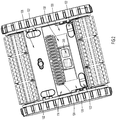
- the autonomous pool cleaner 100 includes a main body 110 with an upper chassis 112 and a lower chassis 114.
- the upper chassis 112 is configured to provide access to an interior cavity 116 that is collectively defined by the upper chassis 112 and the lower chassis 114 (e.g., the upper chassis 112 includes a removable or movable portion that can be removed or moved to provide access to the interior cavity 116).
- the interior cavity 116 is configured to receive a filter, such as filter box 150 and may also house a pump system that is configured to draw fluid (e.g., water), together with any dirt or debris floating therein, into the filter when the filter is installed in the interior cavity 116.
- a filter such as filter box 150
- a pump system that is configured to draw fluid (e.g., water), together with any dirt or debris floating therein, into the filter when the filter is installed in the interior cavity 116.
- the lower chassis 114 of the autonomous vehicle 100 includes a base plate 120.
- the base plate 120 includes a first section 126 and a second section 128.
- the second section 128 is generally configured to support a pump system and/or drive system included in the autonomous vehicle 100 (neither of which are shown for simplicity's sake).
- the pump system need not be disposed in the autonomous robot in order to draw fluid (and debris) into the filter via the intake port.
- the pump system could be disposed in a housing disposed outside of a pool and the suction could be imparted to the autonomous robot via tubing or a tether.
- the first section 126 includes an intake port 130 and is generally configured to support a filter in a position that places the filter in fluid communication with the intake port 130 for a pump system. Consequently, as a pump system draws fluid and dirt/debris into the interior cavity 116, the fluid and dirt/debris enters the filter (e.g., filter box 150).
- the filter e.g., filter box 150
- the filter is configured as a filter box 150 and sits atop of the intake port 130; however, this is merely an example filter that may include the enhanced filter door 200 of the present invention.
- the enhanced filter door 200 may be installed or included on any filter (e.g., a filter box or bag) of any size or shape (including replaceable/removable filters and filters that are permanently installed in an autonomous pool cleaner).
- the filter door 200 is largely described herein in association with a filter, such as filter box 150; however, it is to be understood that the filter door 200 could also be installed directly onto the chassis of an autonomous vehicle, if desired (e.g., the vehicle could collect dirt and debris without a typical filter installed therein).
- the filter door 200 is configured to selectively cover an intake port 130 included on the autonomous vehicle to restrict or control flow of dirt and debris into and out of a filter and/or autonomous pool cleaner. Consequently, the intake port 130 and the filter door 200 may be sized to mate and configured to allow the filter door 200 to selectively seal the intake port 130 (at least with respect to dirt and debris).
- the first section 126 of the base plate 120 may be interchangeable or replaceable (with other first sections/plates 126) to provide intake ports 130 of different shapes/sizes. Consequently, the autonomous robot 100 can utilize filters with doors 200 of different sizes or shapes (since many different filters, such as bags and boxes of different sizes, may require intake ports 130 of different sizes, shapes, and/or locations). Additionally or alternatively, the filter door 200 (and/or the filter) may be sized/shaped for a particular intake port, provided that the intake port 130 and filter door 200 maintain specific points of reference (with respect to each other) that allow the filter door 200 to selectively cover the intake port 130 in a manner that prevents dirt and debris from escaping the filter. That is, a panel 202 (see FIGs. 3-5 ) of the filter door 200 may extend across the intake port 130 when the door 200 is in a closed position (e.g., the panel may span the length and width of a rectangular intake port).
- base plate 120 includes a number of drains 122 covered with one-way valves (e.g., reed valves) and/or screens.
- the first segment 126 includes a drainage vent 124 that may also include a one-way valve (although the one-way valve may be disposed on an interior surface of the base plate 120, instead of the exterior surface of the base plate 120 like the one-way valves or screens included on drains 122).
- drains 122 and vent 124 may assist the filter door 200 in draining water, but not dirt/debris, from the interior cavity 116 of the autonomous robot 100.
- each of drains 122 and vent 124 may include a sieve or filter (such as a fine mesh material) that allows water, but not dirt, to pass therethrough. Then, when the autonomous robot 100 is being removed from a body of water (e.g., a pool), water may drain from the interior cavity 116 to reduce the weight of the robot 100 and make the robot easier to remove from the water.
- a sieve or filter such as a fine mesh material
- the features of the enhanced filter door 200 may eliminate the need for drains 122 and vent 124 (and any other such features); but in other embodiments, these features may assist the filter door 200 in draining the autonomous pool cleaner 100.
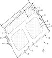
- the enhanced filter door 200 includes a panel 202 with a support structure 208 (e.g., main body) that extends between a first edge 210, that is referred to herein as a pivot edge 210, and a second edge 212, that is referred to herein as a distal or operative edge 212.
- a support structure 208 e.g., main body
- the distal or operative edge 212 is configured to move or rotate about the pivot edge 210 in order to selectively close (e.g., operate) an intake port included on an autonomous pool cleaner and/or filter. That is, the distal or operative edge 212 is configured to move or rotate about the pivot edge 210 in order to selectively move the door 200 into a closed position.
- the support structure 208 also defines one or more drainage openings 204 (the depicted embodiment includes two openings 204) that extend through the panel 202 (e.g., from a top surface 214 to a bottom surface 216) and these drainage openings 204 may be covered by mesh 206.
- the support structure 208 may be overmolded over a panel of mesh 206 so that the mesh 206 is disposed on the bottom surface 216 of the panel 202 and spans the drainage openings 204.
- the mesh 206 may be attached to the bottom surface 216 in any desirable manner.
- the mesh 206 may be attached to the top surface 214 in any desirable manner, provided that the positioning of the filter door 200 is adjusted accordingly (as is discussed in further detail below in connection with FIG. 5 ).
- a portion of mesh 206 also extends beyond the support structure 208 to form an extension 230 that extends beyond a periphery of the panel 202.
- the mesh 206 extends beyond the pivot edge 210 of the support structure 208.
- the extension 230 includes a frame member 236 that may be formed from a rigid plastic material, like that of the support structure 208.
- the frame member 236 extends along the width W of an distal edge (i.e., an exterior edge) of the extension 230 in order to provide at least a portion of the extension 230 with some rigidity or structural definition. However, the frame member 236 does not extend the entire length of the periphery of extension 230. Instead, the extension 230 extends a first distance or length L1 beyond the pivot edge 210 of the support structure 208 of the panel 202 and the frame member 236 extends a distance L2 from the distal edge of the extension 230 (e.g., the edge of the extension 230 furthest from the pivot edge 210). Distance L2 is shorter than distance L1. Consequently, the extension 230 includes a section 238 that is flexible and free to rotate or move (since this section only comprises mesh 206).
- the mesh 206 forming the extension 230 and covering the openings 204 is or acts as a sieve/filter and includes sieve openings that are sized to filter dirt and debris (e.g., retain dirt and debris within the filter area) while allowing fluids, such as water, to pass therethrough. Consequently, when the support structure 208 of the panel 202 is sealed around or onto an intake port 130 (e.g., positioned against the intake port 130), the panel 202 may prevent any dirt and debris from escaping directly through the intake port 130. That is, the mesh 206 may capture or retain dirt and debris. Meanwhile, the mesh 206 of the extension 230 may prevent any dirt or debris from escaping around the pivot edge 210 of the panel 202.
- the filter door 200 may completely seal an intake port 130 with respect to any dirt and debris that is larger than the sieve openings included in the mesh 206.
- the flexible section 238 of the extension 230 provides a living a hinge that biases the door 200 to a closed position with respect to a corresponding intake port 130.
- the flexible section 238 may include or be formed by other materials or components (i.e., plastic components) that provide or enhance the living hinge.
- the filter door 200 may also include a rotatable coupler or couplers 220.
- the filter door 200 includes a rotatable coupler 220 on each side of the panel 202 and each coupler 220 includes a protrusion or hinge 222.
- Each protrusion or hinge 222 is configured to engage a corresponding hole included in a filter to rotatably mount the filter door 200 to the filter. Then, together, the living hinge provided by the flexible section 238 of the extension 230 and the couplers 220 may control the rotation and position of the filter door 200.
- the filter door 200 may not include couplers 220 and, instead, may be rotatably coupled to a filter (or an autonomous vehicle) via only the living hinge provided by the flexible section 238 of the extension 230 (or a living hinge provided by other materials or components disposed in or on the flexible section).
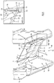
- the filter box 150 includes a mount or engagement portion 152 configured to engage (e.g., be positioned over) the intake port 130 of an autonomous vehicle.
- the mount 152 includes a first section 154 and a second section 156 that extends above the first section 154.
- the mount 152 also includes a support ledge 158 disposed adjacent a transition point between the first section 154 and the second section 156.
- the first section 154 of the mount comprises an annular wall with an inwards taper (e.g., decreasing diameter towards the second section 156) so that the first section 154 defines an opening 140 configured to receive and/or secure the filter 150 to the intake port 130 of the autonomous vehicle 100 (shown in FIG. 1 ).
- the support ledge 158 provides an annular ledge that is disposed in, adjacent to, or abutting the opening 140.
- the support ledge 158 is configured to support the filter door 200 when the filter 200 is in a closed position P1, thereby allowing the filter 200 to control the flow of debris between the intake port 130 and the filter 150.
- the second section 156 of the mount 152 is also an annular wall, but includes generally vertical walls that allow the filter door to rotate out of the closed position P1 (in direction D1) to selectively open the filter box 150 to receive dirt and debris from the intake port 130.
- the filter door 200 is sized to span the entire mount 152 so that, in the closed position P1, the filter door 200 seals the filter 150 and/or intake port 130 and prevents collected dirt and debris from escaping the filter 150 and dispersing back into a pool. Moreover, as can be seen best in the inset view included in FIG. 5 , the extension 230 extends along a wall of the second section 156 of the mount 152 and prevents dirt and debris from entering or escaping through a gap "G" between the pivot edge 210 and the mount 152.
- the mesh 206 is included on the bottom surface 216 of the panel 202 (e.g., the panel is overmolded onto a top surface of the mesh 206), the upward (and substantially vertical) mounting of the extension 230, onto or against the second section 156 of the mount 152, compresses/folds the flexible section 238 of the mesh 206 against its natural resiliency (if the mesh 206 is included on the top surface 214, the door 200 may be mounted upside-down to create the same compression). Consequently, if the panel 202 is rotated open in direction D1, the rotation further compresses/folds the mesh 206 and creates a counteracting force that biases the panel 202 back to its closed position P1.
- the living hinge provided by the flexible section 238 of the extension 230 may bias the door 200 to its closed position P1, in which the door 200 seals/encloses dirt and debris within the filter box 150.
- the frame member 236 of the extension may be secured to the second section 156 of the mount 152 in order to prevent the extension 230 from slipping (with respect to the second section 156 of the mount 152) and ensure that a biasing force is generated by movement of the panel 202 in direction D1 (the biasing force acting in an opposite direction to direction D1).
- the filter door 200 may effectively and efficiently seal dirt and debris within the autonomous robot and/or a filter installed therein. More specifically, once the pump or suction system creates enough suction into the robot (e.g., above a suction threshold), the pressure of the water flow against the straining effect of the mesh 206 of the filter door 200 and/or suction may cause the filter door 200 to rotate in direction D1. With the filter door 200 open, dirt and debris floating in the water may be drawn through opening provided by the open filter door 200, into a robot and/or filter (due to suction from the pump or suction system).
- the biasing force of the living hinge provided by the flexible section 238 will overcome the opening force generated by the pressure and close the door 200, sealing any dirt and debris within the autonomous robot and/or filter.
- the mesh 206 included on the panel 202 may then allow any water in the robot to flow out of the filter and/or robot, as shown by flow Fl, but will prevent any dirt and debris from escaping. Since the door 200 includes its own drainage system, the door 200 may, in some instances, replace at least some drains or vents that are typically included in pool cleaners.
- the filter door 200 is biased to a closed position P1 due to the natural resiliency of the mesh 206 and the positioning of the extension 230. Consequently, biasing members that are liable to malfunction and/or corrode, such as springs, need not be used with the filter door and the filter door may function properly for a long life span. Moreover, since the extension 230 prevents dirt and debris from escaping around the pivot edge 210 of the panel 202 or entering a gap G between the pivot edge 210 and the filter box 150 (or between the pivot edge 210 and the robot 100), the filter door 200 will be less likely to malfunction or deteriorate, as compared to typical filter doors that allow dirt and debris to enter, escape, or be trapped in and around a pivot edge.
- a filter door for an autonomous, submersible vehicle includes mesh material that extends beyond the periphery of a panel to create a living hinge.
- the living hinge biases the panel to a closed position while also allowing water to drain and yet preventing dirt and debris from escaping around a pivot edge of the panel. This increases the life span of the filter door and the cleaning efficiency of the autonomous, submersible vehicle.
- a filter door for an intake port of a filter for a swimming pool cleaner comprises: a support structure with a pivot edge and a distal edge that rotates about the pivot edge in order to selectively move the support structure between a closed position that closes the intake port and an open position that opens the intake port; a mesh attached onto a surface of the support structure; and a living hinge that biases the filter door to the closed position.
- an autonomous swimming pool cleaner comprising: a chassis defining an intake port; a filter that is removably positionable over the intake port, the filter including a door that comprises: a pivot edge and a distal edge that rotates about the pivot edge in order to selectively move the door between a closed position that closes the intake port and an open position that opens the intake port; and a mesh attached onto a surface extending between the pivot edge and the distal edge, the mesh providing a living hinge that biases the door to the closed position.
- the pool cleaner described herein, or portions thereof may be fabricated from any suitable material or combination of materials, such as plastic, foamed plastic, wood, cardboard, pressed paper, metal, supple natural or synthetic materials including, but not limited to, cotton, elastomers, polyester, plastic, rubber, derivatives thereof, and combinations thereof.
- Suitable plastics may include high-density polyethylene (HDPE), low-density polyethylene (LDPE), polystyrene, acrylonitrile butadiene styrene (ABS), polycarbonate, polyethylene terephthalate (PET), polypropylene, ethylene-vinyl acetate (EVA), or the like.
- Suitable foamed plastics may include expanded or extruded polystyrene, expanded or extruded polypropylene, EVA foam, derivatives thereof, and combinations thereof.
- the term “comprises” and its derivations should not be understood in an excluding sense, that is, these terms should not be interpreted as excluding the possibility that what is described and defined may include further elements, steps, etc.
- the term “approximately” and terms of its family should be understood as indicating values very near to those which accompany the aforementioned term. That is to say, a deviation within reasonable limits from an exact value should be accepted, because a skilled person in the art will understand that such a deviation from the values indicated is inevitable due to measurement inaccuracies, etc. The same applies to the terms “about” and “around” and “substantially”.
Landscapes
- Engineering & Computer Science (AREA)
- Architecture (AREA)
- Civil Engineering (AREA)
- Structural Engineering (AREA)
- Life Sciences & Earth Sciences (AREA)
- Hydrology & Water Resources (AREA)
- Environmental & Geological Engineering (AREA)
- Water Supply & Treatment (AREA)
- Chemical & Material Sciences (AREA)
- Organic Chemistry (AREA)
- Filters For Electric Vacuum Cleaners (AREA)
- Filtering Materials (AREA)
- Cleaning By Liquid Or Steam (AREA)
Claims (15)
- Filtertür (200) für eine Einlassöffnung (130) eines Filters für eine Schwimmbecken-Reinigungsvorrichtung (100), die umfasst:eine Trage-Struktur (208) mit einer Schwenk-Kante (210) und einer vorderen Kante (212), die sich um die Schwenk-Kante (210) herum dreht, um die Trage-Struktur (208) selektiv zwischen einer geschlossenen Position (P1), in der die Einlassöffnung (130) geschlossen ist, und einer geöffneten Position zu bewegen, in der die Einlassöffnung (130) geöffnet ist;ein Netz (206), das an einer Oberfläche der Trage-Struktur (208) angebracht ist; gekennzeichnet durchein Filmscharnier, das die Filtertür (200) in die geschlossene Position (P1) spannt.
- Filtertür (200) nach Anspruch 1, wobei die geöffnete Position Eindringen von Flüssigkeit und Schmutz in den Filter zulässt und die geschlossene Position (P1) Durchlass von Schmutz durch die Einlassöffnung (130) verhindert und dabei zulässt, dass das Fluid durch diese hindurchströmt.
- Filtertür (200) nach Anspruch 1 oder 2, wobei sich die Trage-Struktur (208) über die Einlassöffnung (130) erstreckt, wenn sich die Trage-Struktur (208) in der geschlossenen Position (P1) befindet.
- Filtertür (200) nach einem der Ansprüche 1-3, wobei das Netz (206) eine Verlängerung (230) umfasst, die sich über einen äußeren Rand der Trage-Struktur (208) hinaus erstreckt.
- Filtertür (200) nach Anspruch 4, wobei sich die Verlängerung (230) über die Schwenk-Kante (210) hinaus erstreckt, um zu verhindern, dass Schmutz um die Schwenk-Kante (210) herum aus dem Filter austritt, wenn sich die Trage-Struktur (208) in der geöffneten Position, der geschlossenen Position (P1) und dazwischen liegenden Positionen befindet.
- Filtertür (200) nach Anspruch 4 oder 5, wobei die Schwenk-Kante (210) in einem Spalt (G) angeordnet ist, um Drehung der Trage-Struktur (208) in Bezug auf die Einlassöffnung (130) zu ermöglichen, und die Verlängerung (230) verhindert, dass Schmutz in den Spalt (G) gelangt.
- Filtertür (200) nach einem der Ansprüche 4-6, wobei die Verlängerung (230) das Filmscharnier aufweist, das die Filtertür (200) in die geschlossene Position (P1) spannt.
- Filtertür (200) nach einem der Ansprüche 4-7, wobei die Verlängerung (230) umfasst:ein Rahmen-Element (236), das sich entlang einer vorderen Kante der Verlängerung (230) erstreckt; sowieeinen flexiblen Teilabschnitt (238), der zwischen dem Rahmen-Element (236) und der Trage-Struktur (208) angeordnet ist, wobei der flexible Teilabschnitt (238) das Filmscharnier aufweist.
- Filtertür (200) nach einem der Ansprüche 1-8, wobei die Trage-Struktur (208) Ablauf-Öffnungen (204) aufweist und das Netz (206) die Ablauf-Öffnungen (204) überspannt.
- Filtertür (200) nach einem der Ansprüche 1-9, wobei die Filtertür (200) kein SpannElement enthält.
- Autonome Schwimmbecken-Reinigungsvorrichtung (100), die umfasst:ein Chassis (110, 112, 114), das eine Einlassöffnung (130) aufweist;einen Filter, der abnehmbar über der Einlassöffnung (130) positioniert werden kann, wobei der Filter eine Tür (200) enthält, die umfasst:eine Schwenk-Kante (210) sowie eine vordere Kante (212), die sich um die Schwenk-Kante (210) herum dreht, um die Tür (200) selektiv zwischen einer geschlossenen Position (P1), in der die Einlassöffnung (130) geschlossen ist, und einer geöffneten Position zu bewegen, in der die Einlassöffnung (130) geöffnet ist; sowieein Netz (206), das an einer Oberfläche angebracht ist, die sich zwischen der Schwenk-Kante (210) und der vorderen Kante (212) erstreckt, dadurch gekennzeichnet, dass das Netz (206) ein Filmscharnier aufweist, das die Tür (200) in die geschlossene Position (P1) spannt.
- Autonome Schwimmbecken-Reinigungsvorrichtung nach Anspruch 11, wobei der Filter in Fluidverbindung mit der Einlassöffnung (130) steht und die Tür (200) so eingerichtet ist, dass sie einen Strom von Schmutz zwischen dem Filter und der Einlassöffnung (130) steuert.
- Autonome Schwimmbecken-Reinigungsvorrichtung nach Anspruch 11 oder 12, die des Weiteren umfasst:
ein Pump-System, das zum Ansaugen von Wasser und Schmutz in den Filter über die Einlassöffnung (130) eingerichtet ist, wobei die Tür (200) in der geöffneten Position zulässt, dass das Wasser und der Schmutz über die Einlassöffnung (130) in den Filter gelangen, und die Tür (200) in der geschlossenen Position (P1) den Schmutz in dem Filter zurückhält und dabei zulässt, dass das Wasser aus dem Filter austritt - Autonome Schwimmbecken-Reinigungsvorrichtung nach Anspruch 13, wobei das Filmscharnier die Tür (200) in die geschlossene Position (P1) spannt, wenn Druck von dem Wasser und dem Schmutz, die in die Einlassöffnung (130) angesaugt werden, unter einem DruckSchwellenwert liegt.
- Autonome Schwimmbecken-Reinigungsvorrichtung (100) nach einem der Ansprüche 11-14, wobei das Netz (206) umfasst:
eine Verlängerung (230), die sich über einen äußeren Rand der Oberfläche hinaus erstreckt.
Applications Claiming Priority (1)
| Application Number | Priority Date | Filing Date | Title |
|---|---|---|---|
| US201662431576P | 2016-12-08 | 2016-12-08 |
Publications (2)
| Publication Number | Publication Date |
|---|---|
| EP3333343A1 EP3333343A1 (de) | 2018-06-13 |
| EP3333343B1 true EP3333343B1 (de) | 2019-07-24 |
Family
ID=60629525
Family Applications (1)
| Application Number | Title | Priority Date | Filing Date |
|---|---|---|---|
| EP17205988.3A Active EP3333343B1 (de) | 2016-12-08 | 2017-12-07 | Filterklappe für automatische poolroboter |
Country Status (3)
| Country | Link |
|---|---|
| US (1) | US10844621B2 (de) |
| EP (1) | EP3333343B1 (de) |
| ES (1) | ES2744530T3 (de) |
Cited By (1)
| Publication number | Priority date | Publication date | Assignee | Title |
|---|---|---|---|---|
| EP3959397A1 (de) * | 2019-05-29 | 2022-03-02 | Zodiac Pool Care Europe | Bürstenanordnungen, hauptsächlich für automatische schwimmbeckenreiniger |
Families Citing this family (16)
| Publication number | Priority date | Publication date | Assignee | Title |
|---|---|---|---|---|
| US10844621B2 (en) | 2016-12-08 | 2020-11-24 | Zodiac Pool Systems Llc | Enhanced filter door |
| US10364905B2 (en) | 2017-05-11 | 2019-07-30 | Hayward Industries, Inc. | Pool cleaner check valve |
| US10260249B2 (en) * | 2017-07-31 | 2019-04-16 | Maytronics Ltd. | Pool cleaning robot with directional jet thrusts |
| EP3973117B1 (de) * | 2019-05-21 | 2025-02-12 | Intex Marketing Ltd. | Schwimmbeckenreiniger mit beweglichem wasserlauf |
| CN210239261U (zh) * | 2019-05-21 | 2020-04-03 | 明达实业(厦门)有限公司 | 一种水池清洁器的轮刷固定结构 |
| USD950172S1 (en) * | 2020-02-02 | 2022-04-26 | Maytronics Ltd. | Swimming pool cleaner |
| US11161753B1 (en) * | 2021-05-17 | 2021-11-02 | Lisa Rousha Wang | Solar-powered autonomous robotic water surface maintenance and cleaning system |
| USD995018S1 (en) * | 2021-11-19 | 2023-08-08 | Beijing Smorobot Technology Co., Ltd. | Swimming pool cleaning robot |
| CN115248602B (zh) * | 2022-06-13 | 2025-02-07 | 北京众清科技有限公司 | 自动靠岸方法、泳池机器人、电子设备及计算机存储介质 |
| USD1045289S1 (en) * | 2022-10-28 | 2024-10-01 | Yituo Electric Co., Ltd | Underwater cleaner |
| USD1022362S1 (en) * | 2022-11-22 | 2024-04-09 | Degrii Co., Ltd. | Swimming pool cleaner with controller |
| CN116060396B (zh) | 2023-03-20 | 2024-12-13 | 星迈创新科技(苏州)有限公司 | 水池机器人 |
| USD1036034S1 (en) * | 2023-04-18 | 2024-07-16 | Thunder Host Limited | Automatic cleaner for swimming pools |
| USD1060904S1 (en) * | 2023-10-24 | 2025-02-04 | Xingmai Innovation Technology (Suzhou) Co., Ltd. | Automatic swimming pool cleaner |
| USD1109463S1 (en) * | 2024-01-31 | 2026-01-13 | Suzhou Smorobot Technology Co., Ltd. | Robotic pool cleaner |
| USD1123277S1 (en) * | 2024-09-23 | 2026-04-21 | Ningbo POWERFUL Pool Equipment Co., Ltd | Swimming pool cleaning robot |
Family Cites Families (18)
| Publication number | Priority date | Publication date | Assignee | Title |
|---|---|---|---|---|
| US3994260A (en) | 1975-01-15 | 1976-11-30 | Fleshman Roger L | Universal poultry cage |
| ZA767474B (en) | 1976-12-15 | 1978-08-30 | W Rasch | Pool cleaners |
| US4105557A (en) | 1977-03-09 | 1978-08-08 | Weatherholt Brian R | Pool skimmer |
| US4768532A (en) | 1987-01-23 | 1988-09-06 | Jandy Industries | Underwater pool cleaner |
| FR2665209A1 (fr) | 1990-07-25 | 1992-01-31 | Chandler Michael | Dispositif de balai hydraulique pour bassin de piscine et analogue. |
| US5337434A (en) * | 1993-04-12 | 1994-08-16 | Aqua Products, Inc. | Directional control means for robotic swimming pool cleaners |
| US8434182B2 (en) | 1999-01-25 | 2013-05-07 | Aqua Products, Inc. | Pool cleaner with high pressure cleaning jets |
| ES2365729T3 (es) | 2002-01-18 | 2011-10-10 | Smartpool Incorporated | Dispositivo para la limpieza de piscinas. |
| US20080099409A1 (en) | 2006-10-26 | 2008-05-01 | Aquatron Robotic Systems Ltd. | Swimming pool robot |
| CN101285348A (zh) | 2007-04-10 | 2008-10-15 | 胜利宝有限公司 | 一种水池清洁机 |
| US8110098B2 (en) | 2008-11-18 | 2012-02-07 | Pool Bag Limited | Pool cleaning vehicle with filter element and self locking clip |
| US9091093B2 (en) | 2012-07-10 | 2015-07-28 | Aqua Products, Inc. | Internal backwash system for robotic swimming pool cleaner |
| TW201427631A (zh) * | 2013-01-08 | 2014-07-16 | Uni Ring Tech Co Ltd | 自走式清潔裝置 |
| US10378229B2 (en) | 2013-09-08 | 2019-08-13 | .Maytronics Ltd | Pool cleaning robot with bypass mechanism |
| EP2835478B1 (de) | 2014-01-07 | 2016-04-13 | Aquatron Robotic Technology Ltd. | Schwimmbeckenreiniger |
| US9856669B2 (en) | 2014-11-24 | 2018-01-02 | Compurobot Technology Company | Advanced pool cleaner construction |
| US9366049B1 (en) * | 2014-11-24 | 2016-06-14 | Zhibao Pools Company | Jet propelled pool cleaner |
| US10844621B2 (en) | 2016-12-08 | 2020-11-24 | Zodiac Pool Systems Llc | Enhanced filter door |
-
2017
- 2017-12-05 US US15/831,619 patent/US10844621B2/en active Active
- 2017-12-07 ES ES17205988T patent/ES2744530T3/es active Active
- 2017-12-07 EP EP17205988.3A patent/EP3333343B1/de active Active
Non-Patent Citations (1)
| Title |
|---|
| None * |
Cited By (2)
| Publication number | Priority date | Publication date | Assignee | Title |
|---|---|---|---|---|
| EP3959397A1 (de) * | 2019-05-29 | 2022-03-02 | Zodiac Pool Care Europe | Bürstenanordnungen, hauptsächlich für automatische schwimmbeckenreiniger |
| US11795718B2 (en) | 2019-05-29 | 2023-10-24 | Zodiac Pool Care Europe | Brush assemblies principally for automatic swimming pool cleaners |
Also Published As
| Publication number | Publication date |
|---|---|
| US10844621B2 (en) | 2020-11-24 |
| ES2744530T3 (es) | 2020-02-25 |
| EP3333343A1 (de) | 2018-06-13 |
| US20180163422A1 (en) | 2018-06-14 |
Similar Documents
| Publication | Publication Date | Title |
|---|---|---|
| US10844621B2 (en) | Enhanced filter door | |
| US8307485B2 (en) | Apparatus for facilitating maintenance of a pool cleaning device | |
| US12366083B2 (en) | Automatic pool cleaner with edge engagement assembly | |
| EP3082539B1 (de) | Staubbehälter | |
| US20160302637A1 (en) | Autononmous cleaner | |
| US20110088182A1 (en) | Pool cleaning vehicle having an advanced drain system | |
| US20180155946A1 (en) | Docking station for a pool cleaner in a pool | |
| US6054045A (en) | Skimmer filters for ponds | |
| CN111910970B (zh) | 用于游泳池清洁的双重过滤扫帚真空吸尘器 | |
| US20160168872A1 (en) | Advanced pool cleaner construction | |
| CN215836404U (zh) | 一种全自动猫厕所 | |
| CN114587219A (zh) | 自清洁集尘座及集尘系统 | |
| US9951537B2 (en) | Top-bottom pool cleaner including a nose | |
| CN218715549U (zh) | 一种使用方便的水下清洁机器人 | |
| KR20090014689A (ko) | 맨홀 커버장치 | |
| CN115336941B (zh) | 一种吸污装置及清洁设备 | |
| CN216495160U (zh) | 自清洁集尘座及集尘系统 | |
| KR101271141B1 (ko) | 휴대용 어항 청소기 | |
| KR20000069837A (ko) | 유체 베어링 용기의 라이너의 높낮이를 조절하기 위한 장치 | |
| EP4433191B1 (de) | Tragbare fluidfiltervorrichtung | |
| CN119423640A (zh) | 基站的水箱组件以及基站 | |
| CN115306727A (zh) | 一种水泵以及移动消防站 | |
| KR20110053765A (ko) | 로봇청소기의 먼지통 및 이를 구비한 로봇청소기 | |
| CN101392603A (zh) | 水下作业自动清洗设备 | |
| KR101997195B1 (ko) | 이물질 거름팬부를 구비한 하수구 맨홀 장치 |
Legal Events
| Date | Code | Title | Description |
|---|---|---|---|
| PUAI | Public reference made under article 153(3) epc to a published international application that has entered the european phase |
Free format text: ORIGINAL CODE: 0009012 |
|
| STAA | Information on the status of an ep patent application or granted ep patent |
Free format text: STATUS: THE APPLICATION HAS BEEN PUBLISHED |
|
| AK | Designated contracting states |
Kind code of ref document: A1 Designated state(s): AL AT BE BG CH CY CZ DE DK EE ES FI FR GB GR HR HU IE IS IT LI LT LU LV MC MK MT NL NO PL PT RO RS SE SI SK SM TR |
|
| AX | Request for extension of the european patent |
Extension state: BA ME |
|
| STAA | Information on the status of an ep patent application or granted ep patent |
Free format text: STATUS: REQUEST FOR EXAMINATION WAS MADE |
|
| 17P | Request for examination filed |
Effective date: 20181122 |
|
| RBV | Designated contracting states (corrected) |
Designated state(s): AL AT BE BG CH CY CZ DE DK EE ES FI FR GB GR HR HU IE IS IT LI LT LU LV MC MK MT NL NO PL PT RO RS SE SI SK SM TR |
|
| GRAP | Despatch of communication of intention to grant a patent |
Free format text: ORIGINAL CODE: EPIDOSNIGR1 |
|
| STAA | Information on the status of an ep patent application or granted ep patent |
Free format text: STATUS: GRANT OF PATENT IS INTENDED |
|
| INTG | Intention to grant announced |
Effective date: 20190220 |
|
| GRAS | Grant fee paid |
Free format text: ORIGINAL CODE: EPIDOSNIGR3 |
|
| GRAA | (expected) grant |
Free format text: ORIGINAL CODE: 0009210 |
|
| STAA | Information on the status of an ep patent application or granted ep patent |
Free format text: STATUS: THE PATENT HAS BEEN GRANTED |
|
| AK | Designated contracting states |
Kind code of ref document: B1 Designated state(s): AL AT BE BG CH CY CZ DE DK EE ES FI FR GB GR HR HU IE IS IT LI LT LU LV MC MK MT NL NO PL PT RO RS SE SI SK SM TR |
|
| REG | Reference to a national code |
Ref country code: GB Ref legal event code: FG4D |
|
| REG | Reference to a national code |
Ref country code: CH Ref legal event code: EP |
|
| REG | Reference to a national code |
Ref country code: DE Ref legal event code: R096 Ref document number: 602017005534 Country of ref document: DE |
|
| REG | Reference to a national code |
Ref country code: AT Ref legal event code: REF Ref document number: 1158370 Country of ref document: AT Kind code of ref document: T Effective date: 20190815 |
|
| REG | Reference to a national code |
Ref country code: IE Ref legal event code: FG4D |
|
| REG | Reference to a national code |
Ref country code: NL Ref legal event code: MP Effective date: 20190724 |
|
| REG | Reference to a national code |
Ref country code: LT Ref legal event code: MG4D |
|
| REG | Reference to a national code |
Ref country code: AT Ref legal event code: MK05 Ref document number: 1158370 Country of ref document: AT Kind code of ref document: T Effective date: 20190724 |
|
| PG25 | Lapsed in a contracting state [announced via postgrant information from national office to epo] |
Ref country code: FI Free format text: LAPSE BECAUSE OF FAILURE TO SUBMIT A TRANSLATION OF THE DESCRIPTION OR TO PAY THE FEE WITHIN THE PRESCRIBED TIME-LIMIT Effective date: 20190724 Ref country code: LT Free format text: LAPSE BECAUSE OF FAILURE TO SUBMIT A TRANSLATION OF THE DESCRIPTION OR TO PAY THE FEE WITHIN THE PRESCRIBED TIME-LIMIT Effective date: 20190724 Ref country code: HR Free format text: LAPSE BECAUSE OF FAILURE TO SUBMIT A TRANSLATION OF THE DESCRIPTION OR TO PAY THE FEE WITHIN THE PRESCRIBED TIME-LIMIT Effective date: 20190724 Ref country code: SE Free format text: LAPSE BECAUSE OF FAILURE TO SUBMIT A TRANSLATION OF THE DESCRIPTION OR TO PAY THE FEE WITHIN THE PRESCRIBED TIME-LIMIT Effective date: 20190724 Ref country code: NO Free format text: LAPSE BECAUSE OF FAILURE TO SUBMIT A TRANSLATION OF THE DESCRIPTION OR TO PAY THE FEE WITHIN THE PRESCRIBED TIME-LIMIT Effective date: 20191024 Ref country code: PT Free format text: LAPSE BECAUSE OF FAILURE TO SUBMIT A TRANSLATION OF THE DESCRIPTION OR TO PAY THE FEE WITHIN THE PRESCRIBED TIME-LIMIT Effective date: 20191125 Ref country code: NL Free format text: LAPSE BECAUSE OF FAILURE TO SUBMIT A TRANSLATION OF THE DESCRIPTION OR TO PAY THE FEE WITHIN THE PRESCRIBED TIME-LIMIT Effective date: 20190724 Ref country code: AT Free format text: LAPSE BECAUSE OF FAILURE TO SUBMIT A TRANSLATION OF THE DESCRIPTION OR TO PAY THE FEE WITHIN THE PRESCRIBED TIME-LIMIT Effective date: 20190724 Ref country code: BG Free format text: LAPSE BECAUSE OF FAILURE TO SUBMIT A TRANSLATION OF THE DESCRIPTION OR TO PAY THE FEE WITHIN THE PRESCRIBED TIME-LIMIT Effective date: 20191024 |
|
| REG | Reference to a national code |
Ref country code: ES Ref legal event code: FG2A Ref document number: 2744530 Country of ref document: ES Kind code of ref document: T3 Effective date: 20200225 |
|
| PG25 | Lapsed in a contracting state [announced via postgrant information from national office to epo] |
Ref country code: AL Free format text: LAPSE BECAUSE OF FAILURE TO SUBMIT A TRANSLATION OF THE DESCRIPTION OR TO PAY THE FEE WITHIN THE PRESCRIBED TIME-LIMIT Effective date: 20190724 Ref country code: LV Free format text: LAPSE BECAUSE OF FAILURE TO SUBMIT A TRANSLATION OF THE DESCRIPTION OR TO PAY THE FEE WITHIN THE PRESCRIBED TIME-LIMIT Effective date: 20190724 Ref country code: RS Free format text: LAPSE BECAUSE OF FAILURE TO SUBMIT A TRANSLATION OF THE DESCRIPTION OR TO PAY THE FEE WITHIN THE PRESCRIBED TIME-LIMIT Effective date: 20190724 Ref country code: GR Free format text: LAPSE BECAUSE OF FAILURE TO SUBMIT A TRANSLATION OF THE DESCRIPTION OR TO PAY THE FEE WITHIN THE PRESCRIBED TIME-LIMIT Effective date: 20191025 Ref country code: IS Free format text: LAPSE BECAUSE OF FAILURE TO SUBMIT A TRANSLATION OF THE DESCRIPTION OR TO PAY THE FEE WITHIN THE PRESCRIBED TIME-LIMIT Effective date: 20191124 |
|
| PG25 | Lapsed in a contracting state [announced via postgrant information from national office to epo] |
Ref country code: TR Free format text: LAPSE BECAUSE OF FAILURE TO SUBMIT A TRANSLATION OF THE DESCRIPTION OR TO PAY THE FEE WITHIN THE PRESCRIBED TIME-LIMIT Effective date: 20190724 |
|
| PG25 | Lapsed in a contracting state [announced via postgrant information from national office to epo] |
Ref country code: EE Free format text: LAPSE BECAUSE OF FAILURE TO SUBMIT A TRANSLATION OF THE DESCRIPTION OR TO PAY THE FEE WITHIN THE PRESCRIBED TIME-LIMIT Effective date: 20190724 Ref country code: PL Free format text: LAPSE BECAUSE OF FAILURE TO SUBMIT A TRANSLATION OF THE DESCRIPTION OR TO PAY THE FEE WITHIN THE PRESCRIBED TIME-LIMIT Effective date: 20190724 Ref country code: RO Free format text: LAPSE BECAUSE OF FAILURE TO SUBMIT A TRANSLATION OF THE DESCRIPTION OR TO PAY THE FEE WITHIN THE PRESCRIBED TIME-LIMIT Effective date: 20190724 Ref country code: IT Free format text: LAPSE BECAUSE OF FAILURE TO SUBMIT A TRANSLATION OF THE DESCRIPTION OR TO PAY THE FEE WITHIN THE PRESCRIBED TIME-LIMIT Effective date: 20190724 Ref country code: DK Free format text: LAPSE BECAUSE OF FAILURE TO SUBMIT A TRANSLATION OF THE DESCRIPTION OR TO PAY THE FEE WITHIN THE PRESCRIBED TIME-LIMIT Effective date: 20190724 |
|
| PG25 | Lapsed in a contracting state [announced via postgrant information from national office to epo] |
Ref country code: SK Free format text: LAPSE BECAUSE OF FAILURE TO SUBMIT A TRANSLATION OF THE DESCRIPTION OR TO PAY THE FEE WITHIN THE PRESCRIBED TIME-LIMIT Effective date: 20190724 Ref country code: IS Free format text: LAPSE BECAUSE OF FAILURE TO SUBMIT A TRANSLATION OF THE DESCRIPTION OR TO PAY THE FEE WITHIN THE PRESCRIBED TIME-LIMIT Effective date: 20200224 Ref country code: SM Free format text: LAPSE BECAUSE OF FAILURE TO SUBMIT A TRANSLATION OF THE DESCRIPTION OR TO PAY THE FEE WITHIN THE PRESCRIBED TIME-LIMIT Effective date: 20190724 Ref country code: CZ Free format text: LAPSE BECAUSE OF FAILURE TO SUBMIT A TRANSLATION OF THE DESCRIPTION OR TO PAY THE FEE WITHIN THE PRESCRIBED TIME-LIMIT Effective date: 20190724 |
|
| REG | Reference to a national code |
Ref country code: DE Ref legal event code: R097 Ref document number: 602017005534 Country of ref document: DE |
|
| PLBE | No opposition filed within time limit |
Free format text: ORIGINAL CODE: 0009261 |
|
| STAA | Information on the status of an ep patent application or granted ep patent |
Free format text: STATUS: NO OPPOSITION FILED WITHIN TIME LIMIT |
|
| PG2D | Information on lapse in contracting state deleted |
Ref country code: IS |
|
| 26N | No opposition filed |
Effective date: 20200603 |
|
| REG | Reference to a national code |
Ref country code: BE Ref legal event code: MM Effective date: 20191231 |
|
| PG25 | Lapsed in a contracting state [announced via postgrant information from national office to epo] |
Ref country code: SI Free format text: LAPSE BECAUSE OF FAILURE TO SUBMIT A TRANSLATION OF THE DESCRIPTION OR TO PAY THE FEE WITHIN THE PRESCRIBED TIME-LIMIT Effective date: 20190724 Ref country code: MC Free format text: LAPSE BECAUSE OF FAILURE TO SUBMIT A TRANSLATION OF THE DESCRIPTION OR TO PAY THE FEE WITHIN THE PRESCRIBED TIME-LIMIT Effective date: 20190724 |
|
| PG25 | Lapsed in a contracting state [announced via postgrant information from national office to epo] |
Ref country code: IE Free format text: LAPSE BECAUSE OF NON-PAYMENT OF DUE FEES Effective date: 20191207 Ref country code: LU Free format text: LAPSE BECAUSE OF NON-PAYMENT OF DUE FEES Effective date: 20191207 |
|
| PG25 | Lapsed in a contracting state [announced via postgrant information from national office to epo] |
Ref country code: BE Free format text: LAPSE BECAUSE OF NON-PAYMENT OF DUE FEES Effective date: 20191231 |
|
| PG25 | Lapsed in a contracting state [announced via postgrant information from national office to epo] |
Ref country code: CY Free format text: LAPSE BECAUSE OF FAILURE TO SUBMIT A TRANSLATION OF THE DESCRIPTION OR TO PAY THE FEE WITHIN THE PRESCRIBED TIME-LIMIT Effective date: 20190724 |
|
| PG25 | Lapsed in a contracting state [announced via postgrant information from national office to epo] |
Ref country code: HU Free format text: LAPSE BECAUSE OF FAILURE TO SUBMIT A TRANSLATION OF THE DESCRIPTION OR TO PAY THE FEE WITHIN THE PRESCRIBED TIME-LIMIT; INVALID AB INITIO Effective date: 20171207 Ref country code: MT Free format text: LAPSE BECAUSE OF FAILURE TO SUBMIT A TRANSLATION OF THE DESCRIPTION OR TO PAY THE FEE WITHIN THE PRESCRIBED TIME-LIMIT Effective date: 20190724 |
|
| REG | Reference to a national code |
Ref country code: CH Ref legal event code: PL |
|
| PG25 | Lapsed in a contracting state [announced via postgrant information from national office to epo] |
Ref country code: CH Free format text: LAPSE BECAUSE OF NON-PAYMENT OF DUE FEES Effective date: 20201231 Ref country code: LI Free format text: LAPSE BECAUSE OF NON-PAYMENT OF DUE FEES Effective date: 20201231 |
|
| PG25 | Lapsed in a contracting state [announced via postgrant information from national office to epo] |
Ref country code: MK Free format text: LAPSE BECAUSE OF FAILURE TO SUBMIT A TRANSLATION OF THE DESCRIPTION OR TO PAY THE FEE WITHIN THE PRESCRIBED TIME-LIMIT Effective date: 20190724 |
|
| GBPC | Gb: european patent ceased through non-payment of renewal fee |
Effective date: 20211207 |
|
| PG25 | Lapsed in a contracting state [announced via postgrant information from national office to epo] |
Ref country code: GB Free format text: LAPSE BECAUSE OF NON-PAYMENT OF DUE FEES Effective date: 20211207 |
|
| P01 | Opt-out of the competence of the unified patent court (upc) registered |
Effective date: 20230526 |
|
| PGFP | Annual fee paid to national office [announced via postgrant information from national office to epo] |
Ref country code: FR Payment date: 20251226 Year of fee payment: 9 |
|
| PGFP | Annual fee paid to national office [announced via postgrant information from national office to epo] |
Ref country code: ES Payment date: 20260102 Year of fee payment: 9 |
|
| PGFP | Annual fee paid to national office [announced via postgrant information from national office to epo] |
Ref country code: DE Payment date: 20251229 Year of fee payment: 9 |