EP3333285B1 - Electrolytic apparatus - Google Patents
Electrolytic apparatus Download PDFInfo
- Publication number
- EP3333285B1 EP3333285B1 EP16832312.9A EP16832312A EP3333285B1 EP 3333285 B1 EP3333285 B1 EP 3333285B1 EP 16832312 A EP16832312 A EP 16832312A EP 3333285 B1 EP3333285 B1 EP 3333285B1
- Authority
- EP
- European Patent Office
- Prior art keywords
- electrodes
- electrolytic
- case
- holes
- upper plate
- Prior art date
- Legal status (The legal status is an assumption and is not a legal conclusion. Google has not performed a legal analysis and makes no representation as to the accuracy of the status listed.)
- Active
Links
Images


Classifications
-
- C—CHEMISTRY; METALLURGY
- C25—ELECTROLYTIC OR ELECTROPHORETIC PROCESSES; APPARATUS THEREFOR
- C25B—ELECTROLYTIC OR ELECTROPHORETIC PROCESSES FOR THE PRODUCTION OF COMPOUNDS OR NON-METALS; APPARATUS THEREFOR
- C25B1/00—Electrolytic production of inorganic compounds or non-metals
- C25B1/01—Products
- C25B1/02—Hydrogen or oxygen
- C25B1/04—Hydrogen or oxygen by electrolysis of water
-
- C—CHEMISTRY; METALLURGY
- C25—ELECTROLYTIC OR ELECTROPHORETIC PROCESSES; APPARATUS THEREFOR
- C25B—ELECTROLYTIC OR ELECTROPHORETIC PROCESSES FOR THE PRODUCTION OF COMPOUNDS OR NON-METALS; APPARATUS THEREFOR
- C25B11/00—Electrodes; Manufacture thereof not otherwise provided for
-
- C—CHEMISTRY; METALLURGY
- C25—ELECTROLYTIC OR ELECTROPHORETIC PROCESSES; APPARATUS THEREFOR
- C25B—ELECTROLYTIC OR ELECTROPHORETIC PROCESSES FOR THE PRODUCTION OF COMPOUNDS OR NON-METALS; APPARATUS THEREFOR
- C25B11/00—Electrodes; Manufacture thereof not otherwise provided for
- C25B11/02—Electrodes; Manufacture thereof not otherwise provided for characterised by shape or form
- C25B11/036—Bipolar electrodes
-
- C—CHEMISTRY; METALLURGY
- C25—ELECTROLYTIC OR ELECTROPHORETIC PROCESSES; APPARATUS THEREFOR
- C25B—ELECTROLYTIC OR ELECTROPHORETIC PROCESSES FOR THE PRODUCTION OF COMPOUNDS OR NON-METALS; APPARATUS THEREFOR
- C25B11/00—Electrodes; Manufacture thereof not otherwise provided for
- C25B11/04—Electrodes; Manufacture thereof not otherwise provided for characterised by the material
- C25B11/051—Electrodes formed of electrocatalysts on a substrate or carrier
- C25B11/073—Electrodes formed of electrocatalysts on a substrate or carrier characterised by the electrocatalyst material
- C25B11/075—Electrodes formed of electrocatalysts on a substrate or carrier characterised by the electrocatalyst material consisting of a single catalytic element or catalytic compound
- C25B11/081—Electrodes formed of electrocatalysts on a substrate or carrier characterised by the electrocatalyst material consisting of a single catalytic element or catalytic compound the element being a noble metal
-
- C—CHEMISTRY; METALLURGY
- C25—ELECTROLYTIC OR ELECTROPHORETIC PROCESSES; APPARATUS THEREFOR
- C25B—ELECTROLYTIC OR ELECTROPHORETIC PROCESSES FOR THE PRODUCTION OF COMPOUNDS OR NON-METALS; APPARATUS THEREFOR
- C25B9/00—Cells or assemblies of cells; Constructional parts of cells; Assemblies of constructional parts, e.g. electrode-diaphragm assemblies; Process-related cell features
- C25B9/17—Cells comprising dimensionally-stable non-movable electrodes; Assemblies of constructional parts thereof
-
- C—CHEMISTRY; METALLURGY
- C25—ELECTROLYTIC OR ELECTROPHORETIC PROCESSES; APPARATUS THEREFOR
- C25B—ELECTROLYTIC OR ELECTROPHORETIC PROCESSES FOR THE PRODUCTION OF COMPOUNDS OR NON-METALS; APPARATUS THEREFOR
- C25B9/00—Cells or assemblies of cells; Constructional parts of cells; Assemblies of constructional parts, e.g. electrode-diaphragm assemblies; Process-related cell features
- C25B9/60—Constructional parts of cells
- C25B9/63—Holders for electrodes; Positioning of the electrodes
-
- C—CHEMISTRY; METALLURGY
- C25—ELECTROLYTIC OR ELECTROPHORETIC PROCESSES; APPARATUS THEREFOR
- C25B—ELECTROLYTIC OR ELECTROPHORETIC PROCESSES FOR THE PRODUCTION OF COMPOUNDS OR NON-METALS; APPARATUS THEREFOR
- C25B9/00—Cells or assemblies of cells; Constructional parts of cells; Assemblies of constructional parts, e.g. electrode-diaphragm assemblies; Process-related cell features
- C25B9/70—Assemblies comprising two or more cells
- C25B9/73—Assemblies comprising two or more cells of the filter-press type
- C25B9/75—Assemblies comprising two or more cells of the filter-press type having bipolar electrodes
-
- A—HUMAN NECESSITIES
- A61—MEDICAL OR VETERINARY SCIENCE; HYGIENE
- A61K—PREPARATIONS FOR MEDICAL, DENTAL OR TOILETRY PURPOSES
- A61K33/00—Medicinal preparations containing inorganic active ingredients
-
- Y—GENERAL TAGGING OF NEW TECHNOLOGICAL DEVELOPMENTS; GENERAL TAGGING OF CROSS-SECTIONAL TECHNOLOGIES SPANNING OVER SEVERAL SECTIONS OF THE IPC; TECHNICAL SUBJECTS COVERED BY FORMER USPC CROSS-REFERENCE ART COLLECTIONS [XRACs] AND DIGESTS
- Y02—TECHNOLOGIES OR APPLICATIONS FOR MITIGATION OR ADAPTATION AGAINST CLIMATE CHANGE
- Y02E—REDUCTION OF GREENHOUSE GAS [GHG] EMISSIONS, RELATED TO ENERGY GENERATION, TRANSMISSION OR DISTRIBUTION
- Y02E60/00—Enabling technologies; Technologies with a potential or indirect contribution to GHG emissions mitigation
- Y02E60/30—Hydrogen technology
- Y02E60/36—Hydrogen production from non-carbon containing sources, e.g. by water electrolysis
Definitions
- the present invention relates to an electrolytic system, and more particularly, to an electrolytic system having a water tank and an electrolytic device for electrolyzing liquid water and generating hydrogen-oxygen gas.
- instable oxygen species also known as free radicals
- the free radicals are usually generated due to diseases, diet, environment and one's lifestyle, but can be excreted in the form of water by reacting with the inhaled hydrogen.
- the amount of free radicals in the human body can be reduced, thereby restoring the body condition from an acidic state to an alkaline state, achieving an anti-oxidation, anti-aging and beauty health effect, and even eliminating chronic diseases.
- hydrogencontaining gas can be regarded as a kind of health gas, and be generated by liquid water.
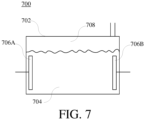
- FIG. 7 shows a schematic diagram of the structure of the traditional hydrogen-oxygen electrolytic device 700.
- the electrolytic device 700 comprises an electrolytic tank 702.
- the electrolytic tank 702 comprises electrodes 706A and 706B.
- the electrodes 706A and 706B are a negative electrode and a positive electrode respectively, coupled to a power source (not shown in FIG. 7 ) for supplying power to electrolyze water.
- the electrolytic water 704 in the electrolytic tank 702 is going to be electrolyzed when going through the electrified electrodes 706A and 706B. And then the negative pole will generate hydrogen and the positive pole will generate oxygen.
- the generated hydrogen and oxygen will be released on the top of the electrolytic tank 702 and then forms a hydrogen-oxygen mixed gas 708.
- the hydrogen-oxygen mixed gas 708 is outputted from the outputting tube of the electrolytic tank 702 for consequent use.
- the quantity of the hydrogen-oxygen gas generated from this kind of electrolytic device is normally limited by the shape and structure of the electro
- the present invention provides an electrolytic system according to independent claim 1.
- the dependent claims show further embodiments of the said electrolytic system.
- the electrolytic system comprises a water tank having a housing forming a hollow space for accommodating water; and an electrolytic device disposed in the hollow space of the water tank.
- the electrolytic device includes: an electrolytic tank comprising a case and a cover coupled to the case, an inner wall of the case having a plurality of engagement structures; a plurality of electrodes coupled to the plurality of engagement structures and arranged separately, wherein the plurality of electrodes comprise a negative pole, a positive pole, and a plurality of bipolar electrodes configured between the negative pole and the positive pole; and an upper plate disposed above the plurality of electrodes and positioned under the cover, wherein the upper plate is made of insulation material and comprises a plurality of protrusions and a plurality of upper holes penetrating through the upper plate, and the upper holes of the upper plate being penetrated by the negative pole and the positive pole; wherein the plurality of electrodes are fixed to the case by injection molding, and the case and the cover defines an inside space of the electrolytic tank.
- the case can be used for accommodating liquid water.
- the plurality of electrodes can be set in the engagement structures respectively to be arranged at intervals in the case.
- the upper plate comprises a plurality of protrusions that can be configured in a gap between the two corresponding electrodes.
- the upper plate can selectively comprise a plurality of holes, corresponded to the gap between the two electrodes.
- the insulation material can selectively be rubber.
- the electrolytic tank can selectively comprise a lower plate, configured on each bottom of the electrodes, and the lower plate is made of insulation material.
- An interval between the bottom of the case and the electrodes might be equal to or greater than 1cm.
- the interval between the bottom of the case and the electrodes can selectively be between 3cm to 4cm.
- the electrolytic tank can selectively comprise a plurality of upper holes, and an electrode channel is formed between the two adjacent electrodes, wherein the electrode channel is corresponded to at least one of the upper holes respectively, and the electrode channel is connected to the outside through corresponding upper holes respectively.
- the electrolytic tank can selectively comprise a plurality of lower holes, and an electrode channel can be formed between the two adjacent electrodes, wherein the electrode channel is corresponded to at least one of the lower holes respectively, and the electrode channel is connected to the outside through the corresponding lower holes respectively.
- the voltage difference of a set of electrolytic electrodes constituted by the two adjacent bipolar electrodes might be between 1.5V to 3V.
- the negative pole and the positive pole might have a rough surface respectively.
- the negative pole and the positive pole can comprise a gold-plated bulge respectively, and the negative pole and the positive pole are connected to a power source through the bulge respectively.
- the distance between the two adjacent electrodes can selectively be between 2mm to 4mm.
- the distance between the two adjacent electrodes can selectively be 3mm.
- an object of the present invention is to provide an electrolytic system having a water tank and an electrolytic device, wherein the electrolytic device can reduce power consumption and the volume of the case through setting the plurality of electrodes in the engagement structures respectively to be arranged at intervals in the case, and the distance between the two adjacent electrodes might be between 2mm to 4mm.
- the interval between the bottom of the case and the electrodes might be equal to or greater than 1cm to avoid the electrodes point discharging within the electrolytic tank.
- the case can be combined closely with the plurality of electrodes to reduce the volume of the case through configuring the plurality of electrodes in the mold and then forming the case by injection molding.
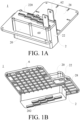
- FIG. 1A and FIG. 1B show a schematic diagram of the electrolytic device 1 in an embodiment with different visual angles of the present invention.
- FIG. 1A and FIG. 1B show the overall appearance of the electrolytic device.
- the electrolytic device 1 comprises an electrolytic tank 2 and a plurality of electrodes 6.
- the plurality of electrodes 6 comprise a negative pole 60 and a positive pole 62.
- the negative pole 60 and the positive pole 62 are connected to an external power source (not shown in the figure) respectively, and the negative pole is connected to the cathode and the positive pole is connected to the anode.
- the plurality of electrodes 6 electrolyze the liquid water between the plurality of electrodes 6 and the electrolytic tank 2 to generate hydrogen-oxygen gas.
- the following statement will explain the design of each unit of the present invention respectively.
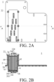
- FIG. 2A and FIG. 2B show a top view diagram and a cross-section diagram crossing along to the A-A line in the top view diagram of the electrolytic device in the embodiment in FIG. 1A of the present invention.
- the electrolytic tank 2 comprises a case 20 used for accommodating liquid water.
- the plurality of electrodes 6 are arranged at intervals in the case 20.
- FIG. 3A and FIG. 3B show a schematic diagram of the case with engagement structures of the electrolytic device in an embodiment with different visual angles of the present invention.
- the case 20 is connected to the plurality of electrodes 6 by injection molding.
- the case 20 can be formed by configuring the plurality of electrodes 6 in the mold and then proceeding injection molding. Namely, by injecting the case material which the designer needs, such as rubber, into the mold contacting with the electrodes closely to form the case 20 combined closely with one or a plurality of electrodes, the problem of time-consuming and labour-consuming due to inserting the electrodes piece by piece into the accommodating space of the case is solved.
- the problem of the difficulty of inserting the electrodes piece by piece into the case because of the requirement of the smaller electrode interval is solved as well. Therefore, the assembly and production of the electrolytic device are more convenient, the low-cost mass production is easier, and the even electrode interval is provided so that the electrode arrangement is easier to be in the precise position. Besides, the reduction of power consumption can reduce the volume of the case when the electrode interval reduces.
- the inner wall of the case 20 comprises a plurality of engagement structures 200, wherein the plurality of electrodes 6 are set in the engagement structures 200 respectively to be arranged at intervals in the case 20 to form a plurality of electrode channels S1.
- the interval between the two adjacent electrodes is 3mm so that not only power consumption but also volume of the case can be reduced; moverover, electrolytic efficiency can be raised. But in application, it is not limited to the above mentioned description; the interval between the two adjacent electrodes can also be between 2mm to 4mm.
- the plurality of engagement structures 200 can be one-piece formed with the case 20 by injection molding.
- FIG. 4A and FIG. 4B show a schematic diagram of the case set with part of the electrodes of the electrolytic device in an embodiment with different visual angles of the present invention. Compared FIG. 2A and FIG. 2B with FIG. 4A and FIG. 4B , it is easier to observe the overall appearance of the engagement structures without the electrodes. But the number or the appearance of the engagement structures is not limited to FIG. 4A and FIG. 4B . In application, the number of the engagement structures can be adjusted according to the number of the electrodes, or the designer can choose the number or the appearance of the engagement structures according to practical requirements.
- the engagement structures 200 can be a bump or a groove.
- the bump is formed by extending from the inner wall of the case 20 to the outside.
- the groove is formed by indenting from the inner wall of the case 20.
- the plurality of electrodes 6 can be set between the two bumps at the both sides of the inner wall of the case respectively by being arranged at intervals in the case to form a plurality of electrode channels S1 .
- the diameter of the bump is between 2mm to 4mm; namely, the interval between the two adj acent electrodes is between 2mm to 4mm.
- the diameter of the bump is 3mm; namely, the interval between the two adjacent electrodes is 3mm.
- the plurality of electrodes 6 can be set between the two grooves at the both sides of the inner wall of the case respectively by being arranged at intervals in the case to form a plurality of electrode channels S1.
- the distance between the two grooves is between 2mm to 4mm; namely, the interval between the two adjacent electrodes is between 2mm to 4mm.
- the distance between the two grooves is 3mm; namely, the interval between the two adjacent electrodes is 3mm.
- FIG. 5A and FIG. 5B show a schematic diagram of the electrolytic tank with the upper plate 24 of the electrolytic device in an embodiment with different visual angles of the present invention.
- the top of the case 20 comprises an opening, and the electrode channels can be connected to the outside through the opening.
- the electrolytic tank further comprises an upper plate 24. The upper plate is configured on the top of the electrolytic tank above the each upper surface F1 of the electrodes to close the opening.
- the upper plate comprises a plurality of protrusions, and the plurality of protrusions can be formed on the surface of the upper plate relatively to the electrode channels.
- the protrusions can be configured between the gap of the two electrodes to isolate the two adjacent electrodes.
- the gap between the two electrodes is the electrode channels S1 .
- the upper plate can be, but not limited to, a rubber mat;
- the upper plate is anything that is made of insulation material.
- the upper plate 24 further comprises a plurality of upper holes 240 corresponded to the gap between the two electrodes. In an embodiment of the present invention, the gap between the two electrodes is the electrode channels S1.
- the electrode channels S1 are corresponded to at least one of the upper holes 240, and the electrode channels S1 are connected to the corresponding upper holes 240 independently.
- the upper holes 240 of the upper plate 24 are connected to the outside, so each electrode channel S1 can be connected to the outside independently. Therefore, the upper holes can output the hydrogen-oxygen gas generated by electrolyzing the liquid water from the case, but not limited to this.
- the upper holes 240 can even allow the liquid water from the outside to get inside the case and then flow into the electrode channels S1 .
- the upper holes 240 are penetrated by the negative pole and the positive pole, so that the negative pole and the positive pole can be connected to the power source (not shown in the figure).
- the lower plate comprises a plurality of protrusions, and the plurality of protrusions can be formed on the surface of the lower plate relatively to the electrode channels.
- the protrusions can be configured between the gap of the two electrodes to isolate the two adjacent electrodes.
- the gap between the two electrodes is the electrode channels S1.
- the lower plate can be, but not limited to, a rubber mat; in application, the lower plate can be anything that is made of insulation material.
- the lower plate further comprises a plurality of lower holes corresponded to the gap between the two electrodes. In an embodiment of the present invention, the gap between the two electrodes is the electrode channels S1.
- the electrode channels S1 are corresponded to at least one of the lower holes, and the electrode channels S1 are connected to the corresponding lower holes independently.
- the lower holes of the lower plate are connected to the outside, so each electrode channel S1 can be connected to the outside independently. Therefore, the lower holes can allow the liquid water from the outside to get inside the case 20 and then flow into the electrode channels S1.
- the electrolytic device is configured in the water tank, and might even set firmly in the water tank dangly.
- the water tank comprises a hollow space for accommodating liquid water.
- the hollow space of the water tank can be connected to the electrode channels through the upper holes of the electrolytic tank so that the hydrogen-oxygen gas generated by electrolyzing the liquid water can be outputted from the case through the upper holes, and the liquid water can even enter the case and then get into the electrode channels S1 through the upper holes and the water tank.
- the hollow space of the water tank can be connected to the lower holes, so the liquid water can get inside the case and then flow into the electrode channels S1 through the lower holes and the water tank.
- the case is a groove.
- the electrolytic tank 2 further comprises a plurality of lower holes 202.
- the lower holes 202 can penetrate through the inside surface and the outside surface of the case 20.
- an electrode channel S1 is formed between the two adjacent electrodes 6.
- the electrode channels S1 are corresponded to lower holes 202 respectively and connected to the corresponding lower holes on the bottom of the case 20 independently. But it is not limited to the above and the lower holes shown in FIG. 2B .
- the electrode channels can also be corresponded to at least one of the lower holes respectively; namely, the designer can choose the exterior and the number of the lower holes corresponded to the electrode channels according to the actual demand.
- Each electrode channel can be connected to the outside through the corresponding lower holes 202 independently, so the lower holes 202 can allow the liquid water from the outside to get inside the case 20 and then flow into the electrode channels S1.
- the thickness of the lower plate is, but not limited to, between 3cm to 4cm, so that the distance between the bottom of the case and the electrodes is between 3cm to 4cm.
- the thickness of the lower plate can be greater than 1cm, so that the distance between the bottom of the case and the electrodes can be greater than 1cm.
- the lower plate 26 further comprises a plurality of lower holes 260.
- the electrode channels S1 can be connected to the lower holes 202 of the bottom of the case 20 through the lower holes 260 of the lower plate 26 and can also be connected to the outside through the lower holes 260 and the lower holes 202. Therefore, the liquid water can enter inside the case 20 and then flow into the electrode channels S1 from the outside through the lower holes 202 and the lower holes 260.
- the electrolytic tank further comprises a plurality of upper holes.
- the electrolytic tank further comprises a upper plate 24 configured on each upper surface of the electrodes 6, wherein the upper plate 24 comprises a plurality of upper holes 240.
- the electrode channels S1 are corresponded to at least one of the upper holes 240 respectively, and the electrode channels S1 are connected to the corresponding upper holes 240 independently.
- the upper holes 240 of the upper plate 24 are connected to the outside, so each electrode channel S1 can be connected to the outside independently. Therefore, the upper holes can output the hydrogen-oxygen gas generated by electrolyzing the liquid water from the case, but not limited to this.
- the upper holes can even allow the liquid water from the outside to get inside the case and then flow into the electrode channels S1. Beside, the upper holes can be penetrated by the negative pole and the positive pole, so that the negative pole and the positive pole can be connected to the power source (not shown in the figure).
- the electrolytic tank 2 further comprises a cover 22, wherein the cover 22 comprises a plurality of upper holes 220. But the number and the exterior of the upper holes 220 are not limited to FIG. 1A .
- the cover 22 is configured on the case 20 and the upper plate 24, and the upper holes 220 of the cover 22 are connected to the upper holes 240 of the upper plate 24.
- the electrode channels S1 can be connected to the upper holes 220 of the cover 22 through the upper holes 240 of the upper plate 24, and the electrode channels S1 are connected to the outside through the upper holes 220, so that each electrode channel S1 can be connected to the outside independently.
- the upper holes 240 of the upper plate 24 and the upper holes 220 of the cover 22 can output the hydrogen-oxygen gas generated by electrolyzing the liquid water from the case, but not limited to this.
- the upper holes 240 of the upper plate 24 and the upper holes 220 of the cover 22 can even allow the liquid water from the outside to get inside the case and then flow into the electrode channels S1 .
- the upper holes 240 of the upper plate 24 and the upper holes 220 of the cover 22 can be penetrated by the negative pole and the positive pole, so that the negative pole and the positive pole can be connected to the power source.
- the electrolytic device is configured in the water tank, and might be even set firmly in the water tank dangly.
- the water tank comprises a hollow space for accommodating liquid water.
- the hollow space of the water tank can be connected to the electrode channels through the upper holes of the electrolytic tank so that the hydrogen-oxygen gas generated by electrolyzing the liquid water can be outputted from the case through the upper holes, and the liquid water can even enter the case and then flow into the electrode channels S1 through the upper holes and the water tank.
- the hollow space of the water tank can be connected to the lower holes, and the liquid water can enter the case and then flow into the electrode channels S1 through the lower holes and the water tank.
- the electrolytic tank 2 can comprise a separator 28 (shown in FIG. 1A ).
- the separator 28 is formed from the side surface of the case 2 corresponded to the water tank extending to the outside.
- the exterior of the separator 28 is not limited to the figures, in application, the exterior form can be chosen depending on the internal structure of the water tank.
- the separator 28 is, but not limited to, a one-piece formed with the case 20.
- the user can also decide whether to configure the separator on the outside of the case according to the demand.
- the case and the separator are formed as a one-piece by a mold with the separator and the case construction processing injection molding.
- the electrolytic tank 2 when the electrolytic tank is configured in the water tank, the electrolytic tank 2 can split the hollow space of the water tank into upper part and lower part through the separator 28.
- the upper part of the hollow space of the water tank can be connected to the upper holes of the electrolytic tank, and the hydrogen-oxygen gas generated by electrolyzing the liquid water can be outputted from the case through the upper holes, and the liquid water can even enter the case and then flow into the electrode channels S1 through the upper holes and the upper part of the hollow space of the water tank.
- the lower part of the hollow space of the water tank can be connected to the lower holes of the electrolytic tank, and the liquid water can enter the case and then flow into the electrode channels S1 through the lower holes and the lower part of the hollow space of the water tank.
- the plurality of electrodes 6 are the negative pole 60, the positive pole 62, and the plurality of bipolar electrodes 64.
- the plurality of bipolar electrodes 64 are configured between the negative pole 60 and the positive pole 62 arranged at intervals.
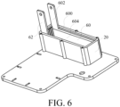
- the negative pole 60 might have a rough surface (shown in FIG. 6 ) and the positive pole 62 might also have a rough surface (not shown in the figure).
- the electrolytic area of the negative pole 60 and the positive pole 62 are increased by the brushing method to roughen the surface of the negative pole and the positive pole.
- FIG. 6 shows a schematic diagram of the case of the electrolytic device configured with positive pole and negative pole in an embodiment of the present invention.
- the negative pole 60 comprises a metal layer 600 (shown in FIG. 3B and FIG. 6 ) and the positive pole 62 comprises a metal layer 620 (shown in FIG. 3A ).
- the negative pole 60 and the positive pole 62 are connected to the power source (not shown in the figure) through the metal layer respectively.
- the area size of the metal layer is not limited to FIG. 6 and can be adjust according to practical application.
- the negative pole and the positive pole can comprise a gold-plated bulge 602, 622 (shown in FIG. 3A and FIG. 3B ) respectively, and the negative pole 60 and the positive pole 62 are connected to the power source through the bulge 602, 622 respectively.
- the negative pole 60 can be connected to the cathode and the positive pole 62 can be connected to the anode, wherein the voltage difference of a set of electrolytic electrodes constituted by the two adjacent bipolar electrodes 64 is between 1.5V to 3V.
- the voltage difference of a set of electrolytic electrodes constituted by the negative pole 60 and the bipolar electrodes 64 is between 1.5V to 3V.
- the voltage difference of a set of electrolytic electrodes constituted by the bipolar electrodes 64 and the bipolar electrodes 64 is between 1.5V to 3V.
- the voltage difference of a set of electrolytic electrodes constituted by the bipolar electrodes 64 and the positive pole 62 is between 1.5V to 3V.
- the output voltage difference of the power source is between 17V to 27V, and the output electric current of the power source is between 30A to 40A; namely, the electrolytic device generates air output between 1.5L to 4.0L per minute.
- the voltage difference of a set of electrolytic electrodes (between the cathode and the anode) in use is between 1.5V to 3V; for example, the voltage difference of eight sets of electrolytic electrodes in use is between 12V to 24V. But it is not limited to the above mentioned description.
- the output voltage difference of the power source is between 5V to 27V, and the output electric current of the power source is between 2A to 150A; namely, the power of the power source is between 10W (5V*2A) and 3600W (24V*150A), and the electrolytic device generates air output between 0.01L and 12L per minute.
- an object of the present invention is to provide an electrolytic system having a water tank and an electrolytic device.
- the electrolytic device of the present invention can reduce power consumption and reduce the volume of the case and increase overall efficiency through setting the plurality of electrodes in the engagement structures respectively to be arranged at intervals in the case, and the distance between the two adjacent electrodes might be between 2mm to 4mm.
- the interval between the bottom of the case and the electrodes might be equal to or greater than 1cm to avoid the electrodes point discharging within the electrolytic tank.
- the case combined closely with the plurality of electrodes through configuring the plurality of electrodes in the mold and then forming the case by injection molding can solve the problem of time-consuming and labour-consuming due to inserting the electrodes piece by piece into the accommodating space of the case. Therefore, the assembly and production of the electrolytic device are more convenient, the low-cost mass production is easier, and the even electrode interval is provided so that the electrode arrangement is easier to be in the precise position.
Landscapes
- Chemical & Material Sciences (AREA)
- Engineering & Computer Science (AREA)
- Organic Chemistry (AREA)
- Metallurgy (AREA)
- Materials Engineering (AREA)
- Electrochemistry (AREA)
- Chemical Kinetics & Catalysis (AREA)
- Inorganic Chemistry (AREA)
- Health & Medical Sciences (AREA)
- Epidemiology (AREA)
- Veterinary Medicine (AREA)
- Public Health (AREA)
- General Health & Medical Sciences (AREA)
- Animal Behavior & Ethology (AREA)
- Life Sciences & Earth Sciences (AREA)
- Pharmacology & Pharmacy (AREA)
- Medicinal Chemistry (AREA)
- Electrolytic Production Of Non-Metals, Compounds, Apparatuses Therefor (AREA)
- Water Treatment By Electricity Or Magnetism (AREA)
- Filling, Topping-Up Batteries (AREA)
Description
- The present invention relates to an electrolytic system, and more particularly, to an electrolytic system having a water tank and an electrolytic device for electrolyzing liquid water and generating hydrogen-oxygen gas.
- People are always paying much attention on health developments. Many developments in medical technology are often targeted towards treating diseases and prolonging human life. Most of the treatments in the past are passive, which means that the disease is only treated when the disease occurs. The medical treatments include an operation, a medication treatment, a radiation therapy, or even medical treatment for cancer. But in recent years, most of the researches from medical experts are gradually moving towards preventive medical methods, such as research on healthy food, screening and preventing inherited diseases, which actively prevents diseases from occurring in the future. Because of this focus on prolonging human life, many anti-aging and anti-oxidation technologies including skin care products and anti-oxidation food/medicine are gradually being developed and have become increasingly popular to the general public.
- Studies have found that there are instable oxygen species (O+), also known as free radicals, in the human body. The free radicals are usually generated due to diseases, diet, environment and one's lifestyle, but can be excreted in the form of water by reacting with the inhaled hydrogen. With this method, the amount of free radicals in the human body can be reduced, thereby restoring the body condition from an acidic state to an alkaline state, achieving an anti-oxidation, anti-aging and beauty health effect, and even eliminating chronic diseases. Furthermore, there are also clinical experiments showing that patients who need to inhale a high concentration of oxygen for an extended period of time would experience lung damage and the lung damage could be ameliorated by inhaling hydrogen. In conclusion, hydrogencontaining gas can be regarded as a kind of health gas, and be generated by liquid water.
- Please refer to
FIG. 7, FIG. 7 shows a schematic diagram of the structure of the traditional hydrogen-oxygenelectrolytic device 700. Theelectrolytic device 700 comprises anelectrolytic tank 702. Theelectrolytic tank 702 compriseselectrodes electrodes FIG. 7 ) for supplying power to electrolyze water. Theelectrolytic water 704 in theelectrolytic tank 702 is going to be electrolyzed when going through theelectrified electrodes electrolytic tank 702 and then forms a hydrogen-oxygen mixedgas 708. The hydrogen-oxygen mixedgas 708 is outputted from the outputting tube of theelectrolytic tank 702 for consequent use. However, the quantity of the hydrogen-oxygen gas generated from this kind of electrolytic device is normally limited by the shape and structure of the electrolytic tank. -
- The present invention provides an electrolytic system according to
independent claim 1. The dependent claims show further embodiments of the said electrolytic system. - The electrolytic system comprises a water tank having a housing forming a hollow space for accommodating water; and an electrolytic device disposed in the hollow space of the water tank.
- The electrolytic device includes: an electrolytic tank comprising a case and a cover coupled to the case, an inner wall of the case having a plurality of engagement structures; a plurality of electrodes coupled to the plurality of engagement structures and arranged separately, wherein the plurality of electrodes comprise a negative pole, a positive pole, and a plurality of bipolar electrodes configured between the negative pole and the positive pole; and an upper plate disposed above the plurality of electrodes and positioned under the cover, wherein the upper plate is made of insulation material and comprises a plurality of protrusions and a plurality of upper holes penetrating through the upper plate, and the upper holes of the upper plate being penetrated by the negative pole and the positive pole; wherein the plurality of electrodes are fixed to the case by injection molding, and the case and the cover defines an inside space of the electrolytic tank.
- The case can be used for accommodating liquid water. The plurality of electrodes can be set in the engagement structures respectively to be arranged at intervals in the case.
- The upper plate comprises a plurality of protrusions that can be configured in a gap between the two corresponding electrodes.
- The upper plate can selectively comprise a plurality of holes, corresponded to the gap between the two electrodes. The insulation material can selectively be rubber.
- The electrolytic tank can selectively comprise a lower plate, configured on each bottom of the electrodes, and the lower plate is made of insulation material.
- An interval between the bottom of the case and the electrodes might be equal to or greater than 1cm.
- The interval between the bottom of the case and the electrodes can selectively be between 3cm to 4cm.
- The electrolytic tank can selectively comprise a plurality of upper holes, and an electrode channel is formed between the two adjacent electrodes, wherein the electrode channel is corresponded to at least one of the upper holes respectively, and the electrode channel is connected to the outside through corresponding upper holes respectively.
- The electrolytic tank can selectively comprise a plurality of lower holes, and an electrode channel can be formed between the two adjacent electrodes, wherein the electrode channel is corresponded to at least one of the lower holes respectively, and the electrode channel is connected to the outside through the corresponding lower holes respectively.
- The voltage difference of a set of electrolytic electrodes constituted by the two adjacent bipolar electrodes might be between 1.5V to 3V.
- The negative pole and the positive pole might have a rough surface respectively.
- The negative pole and the positive pole can comprise a gold-plated bulge respectively, and the negative pole and the positive pole are connected to a power source through the bulge respectively.
- The distance between the two adjacent electrodes can selectively be between 2mm to 4mm.
- The distance between the two adjacent electrodes can selectively be 3mm.
- In conclusion, an object of the present invention is to provide an electrolytic system having a water tank and an electrolytic device, wherein the electrolytic device can reduce power consumption and the volume of the case through setting the plurality of electrodes in the engagement structures respectively to be arranged at intervals in the case, and the distance between the two adjacent electrodes might be between 2mm to 4mm. The interval between the bottom of the case and the electrodes might be equal to or greater than 1cm to avoid the electrodes point discharging within the electrolytic tank. The case can be combined closely with the plurality of electrodes to reduce the volume of the case through configuring the plurality of electrodes in the mold and then forming the case by injection molding.
- Some of the embodiments will be described in detail, with reference to the following figures, wherein like designations denote like members, wherein:
-
FIG. 1A and FIG. 1B show a schematic diagram of the electrolytic device in an embodiment with different visual angles of the present invention. -
FIG. 2A and FIG. 2B show a top view diagram and a cross-section diagram crossing along to the A-A line in the top view diagram of the electrolytic device in the embodiment inFIG. 1A of the present invention. -
FIG. 3A and FIG. 3B show a schematic diagram of the case with engagement structures of the electrolytic device in an embodiment with different visual angles of the present invention. -
FIG. 4A and FIG. 4B show a schematic diagram of the case set with part of the electrodes of the electrolytic device in an embodiment with different visual angles of the present invention. -
FIG. 5A and FIG. 5B show a schematic diagram of the electrolytic tank with an upper plate of the electrolytic device in an embodiment with different visual angles of the present invention. -
FIG. 6 shows a schematic diagram of the case of the electrolytic device configured with positive pole and negative pole in an embodiment of the present invention. -
FIG. 7 shows a schematic diagram of the structure of the traditional electrolytic device. - A detailed description of the hereinafter described embodiments of the disclosed apparatus and method are presented herein by way of exemplification and not limitation with reference to the Figures. Although certain embodiments are shown and described in detail, it should be understood that various changes and modifications may be made without departing from the scope of the appended claims. The scope of the present invention will in no way be limited to the number of constituting components, the materials thereof, the shapes thereof, the relative arrangement thereof, etc., and are disclosed simply as an example of embodiments of the present invention.
- Please refer to
FIG. 1A and FIG. 1B. FIG. 1A and FIG. 1B show a schematic diagram of theelectrolytic device 1 in an embodiment with different visual angles of the present invention.FIG. 1A and FIG. 1B show the overall appearance of the electrolytic device. Theelectrolytic device 1 comprises anelectrolytic tank 2 and a plurality ofelectrodes 6. The plurality ofelectrodes 6 comprise anegative pole 60 and apositive pole 62. In application, thenegative pole 60 and thepositive pole 62 are connected to an external power source (not shown in the figure) respectively, and the negative pole is connected to the cathode and the positive pole is connected to the anode. The plurality ofelectrodes 6 electrolyze the liquid water between the plurality ofelectrodes 6 and theelectrolytic tank 2 to generate hydrogen-oxygen gas. The following statement will explain the design of each unit of the present invention respectively. - First, please refer to
FIG. 2A and FIG. 2B. FIG. 2A and FIG. 2B show a top view diagram and a cross-section diagram crossing along to the A-A line in the top view diagram of the electrolytic device in the embodiment inFIG. 1A of the present invention. Theelectrolytic tank 2 comprises acase 20 used for accommodating liquid water. The plurality ofelectrodes 6 are arranged at intervals in thecase 20. - Please refer to
FIG. 3A and FIG. 3B. FIG. 3A and FIG. 3B show a schematic diagram of the case with engagement structures of the electrolytic device in an embodiment with different visual angles of the present invention. Thecase 20 is connected to the plurality ofelectrodes 6 by injection molding. In an embodiment of the present invention, thecase 20 can be formed by configuring the plurality ofelectrodes 6 in the mold and then proceeding injection molding. Namely, by injecting the case material which the designer needs, such as rubber, into the mold contacting with the electrodes closely to form thecase 20 combined closely with one or a plurality of electrodes, the problem of time-consuming and labour-consuming due to inserting the electrodes piece by piece into the accommodating space of the case is solved. At the same time, the problem of the difficulty of inserting the electrodes piece by piece into the case because of the requirement of the smaller electrode interval is solved as well. Therefore, the assembly and production of the electrolytic device are more convenient, the low-cost mass production is easier, and the even electrode interval is provided so that the electrode arrangement is easier to be in the precise position. Besides, the reduction of power consumption can reduce the volume of the case when the electrode interval reduces. - Please refer to
FIG. 3A and FIG. 3B . The inner wall of thecase 20 comprises a plurality ofengagement structures 200, wherein the plurality ofelectrodes 6 are set in theengagement structures 200 respectively to be arranged at intervals in thecase 20 to form a plurality of electrode channels S1. The interval between the two adjacent electrodes is 3mm so that not only power consumption but also volume of the case can be reduced; moverover, electrolytic efficiency can be raised. But in application, it is not limited to the above mentioned description; the interval between the two adjacent electrodes can also be between 2mm to 4mm. In an embodiment of the present invention, the plurality ofengagement structures 200 can be one-piece formed with thecase 20 by injection molding. - Please refer to
FIG. 4A and FIG. 4B. FIG. 4A and FIG. 4B show a schematic diagram of the case set with part of the electrodes of the electrolytic device in an embodiment with different visual angles of the present invention. ComparedFIG. 2A and FIG. 2B withFIG. 4A and FIG. 4B , it is easier to observe the overall appearance of the engagement structures without the electrodes. But the number or the appearance of the engagement structures is not limited toFIG. 4A and FIG. 4B . In application, the number of the engagement structures can be adjusted according to the number of the electrodes, or the designer can choose the number or the appearance of the engagement structures according to practical requirements. - In an embodiment of the present invention, the
engagement structures 200 can be a bump or a groove. The bump is formed by extending from the inner wall of thecase 20 to the outside. The groove is formed by indenting from the inner wall of thecase 20. In an embodiment of the present invention, the plurality ofelectrodes 6 can be set between the two bumps at the both sides of the inner wall of the case respectively by being arranged at intervals in the case to form a plurality of electrode channels S1. The diameter of the bump is between 2mm to 4mm; namely, the interval between the two adj acent electrodes is between 2mm to 4mm. In a better embodiment of the present invention, the diameter of the bump is 3mm; namely, the interval between the two adjacent electrodes is 3mm. In another embodiment of the present invention, the plurality ofelectrodes 6 can be set between the two grooves at the both sides of the inner wall of the case respectively by being arranged at intervals in the case to form a plurality of electrode channels S1. The distance between the two grooves is between 2mm to 4mm; namely, the interval between the two adjacent electrodes is between 2mm to 4mm. In a better embodiment of the present invention, the distance between the two grooves is 3mm; namely, the interval between the two adjacent electrodes is 3mm. - Please refer to
FIG. 3A, FIG. 3B ,FIG. 5A and FIG. 5B. FIG. 5A and FIG. 5B show a schematic diagram of the electrolytic tank with theupper plate 24 of the electrolytic device in an embodiment with different visual angles of the present invention. AsFIG. 3A and FIG. 3B show, in an embodiment of the present invention, the top of thecase 20 comprises an opening, and the electrode channels can be connected to the outside through the opening. Please refer toFIG. 5A and FIG. 5B , the electrolytic tank further comprises anupper plate 24. The upper plate is configured on the top of the electrolytic tank above the each upper surface F1 of the electrodes to close the opening. The upper plate comprises a plurality of protrusions, and the plurality of protrusions can be formed on the surface of the upper plate relatively to the electrode channels. When the upper plate is configured above the each upper surface F1 of the electrodes, the protrusions can be configured between the gap of the two electrodes to isolate the two adjacent electrodes. In an embodiment of the present invention, the gap between the two electrodes is the electrode channels S1. The upper plate can be, but not limited to, a rubber mat; The upper plate is anything that is made of insulation material. Theupper plate 24 further comprises a plurality ofupper holes 240 corresponded to the gap between the two electrodes. In an embodiment of the present invention, the gap between the two electrodes is the electrode channels S1. But the exterior and the number of theupper holes 240 is not limited toFIG. 5A and FIG. 5B . The electrode channels S1 are corresponded to at least one of theupper holes 240, and the electrode channels S1 are connected to the correspondingupper holes 240 independently. Theupper holes 240 of theupper plate 24 are connected to the outside, so each electrode channel S1 can be connected to the outside independently. Therefore, the upper holes can output the hydrogen-oxygen gas generated by electrolyzing the liquid water from the case, but not limited to this. Theupper holes 240 can even allow the liquid water from the outside to get inside the case and then flow into the electrode channels S1. Theupper holes 240 are penetrated by the negative pole and the positive pole, so that the negative pole and the positive pole can be connected to the power source (not shown in the figure). - In an embodiment of the present invention, the bottom of the
case 20 comprises an opening (not shown inFIG. 3A and FIG. 3B , and the exterior is the same as the opening on the top inFIG. 3A and FIG. 3B ), and the electrode channels can be connected to the outside through the opening. In an embodiment of the present invention, the electrolytic tank further comprises a lower plate (not shown inFIG. 5A and FIG. 5B , and the exterior and the setting way are the same as the upper plate inFIG. 5A and FIG. 5B ). The lower plate can be configured on the bottom of the electrolytic tank below the each lower surface of the electrodes (relative to the lower surface of the electrodes) to close the opening. In an embodiment of the present invention, the lower plate comprises a plurality of protrusions, and the plurality of protrusions can be formed on the surface of the lower plate relatively to the electrode channels. When the lower plate is configured below the each lower surface of the electrodes, the protrusions can be configured between the gap of the two electrodes to isolate the two adjacent electrodes. In an embodiment of the present invention, the gap between the two electrodes is the electrode channels S1. The lower plate can be, but not limited to, a rubber mat; in application, the lower plate can be anything that is made of insulation material. The lower plate further comprises a plurality of lower holes corresponded to the gap between the two electrodes. In an embodiment of the present invention, the gap between the two electrodes is the electrode channels S1. The electrode channels S1 are corresponded to at least one of the lower holes, and the electrode channels S1 are connected to the corresponding lower holes independently. The lower holes of the lower plate are connected to the outside, so each electrode channel S1 can be connected to the outside independently. Therefore, the lower holes can allow the liquid water from the outside to get inside thecase 20 and then flow into the electrode channels S1. - The electrolytic device is configured in the water tank, and might even set firmly in the water tank dangly. The water tank comprises a hollow space for accommodating liquid water. The hollow space of the water tank can be connected to the electrode channels through the upper holes of the electrolytic tank so that the hydrogen-oxygen gas generated by electrolyzing the liquid water can be outputted from the case through the upper holes, and the liquid water can even enter the case and then get into the electrode channels S1 through the upper holes and the water tank. The hollow space of the water tank can be connected to the lower holes, so the liquid water can get inside the case and then flow into the electrode channels S1 through the lower holes and the water tank.
- Please refer to
FIG. 1B andFIG. 2B again. In another embodiment of the present invention, the case is a groove. AsFIG. 1B shows, theelectrolytic tank 2 further comprises a plurality oflower holes 202. Thelower holes 202 can penetrate through the inside surface and the outside surface of thecase 20. AsFIG. 2B shows, an electrode channel S1 is formed between the twoadjacent electrodes 6. The electrode channels S1 are corresponded tolower holes 202 respectively and connected to the corresponding lower holes on the bottom of thecase 20 independently. But it is not limited to the above and the lower holes shown inFIG. 2B . In application, the electrode channels can also be corresponded to at least one of the lower holes respectively; namely, the designer can choose the exterior and the number of the lower holes corresponded to the electrode channels according to the actual demand. Each electrode channel can be connected to the outside through the correspondinglower holes 202 independently, so thelower holes 202 can allow the liquid water from the outside to get inside thecase 20 and then flow into the electrode channels S1. - Please refer to
FIG. 2B again. AsFIG. 2B shows, the distance between the bottom of thecase 20 and theelectrodes 6 is between 3cm to 4cm to avoid the electrodes point discharging within the electrolytic tank. But it is not limited to the above, in application, the distance between the bottom of the case and the electrodes can be greater than 1cm. In an embodiment of the present invention, alower plate 26 is configured between the bottom of thecase 20 and theelectrodes 6. Thelower plate 26 is set between the inner surface of the bottom of thecase 20 and the lower surface of theelectrodes 6 to avoid the distance between theelectrodes 6 and the bottom of thecase 20 being too close to cause the electrodes point discharging. In the embodiment of the present invention, the thickness of the lower plate is, but not limited to, between 3cm to 4cm, so that the distance between the bottom of the case and the electrodes is between 3cm to 4cm. In application, the thickness of the lower plate can be greater than 1cm, so that the distance between the bottom of the case and the electrodes can be greater than 1cm. - Furthermore, please refer to
FIG. 1B andFIG. 2B again. AsFIG. 2B shows, thelower plate 26 further comprises a plurality oflower holes 260. The electrode channels S1can be connected to thelower holes 202 of the bottom of thecase 20 through thelower holes 260 of thelower plate 26 and can also be connected to the outside through thelower holes 260 and thelower holes 202. Therefore, the liquid water can enter inside thecase 20 and then flow into the electrode channels S1 from the outside through thelower holes 202 and thelower holes 260. - The electrolytic tank further comprises a plurality of upper holes. As
FIG. 2B shows, in an embodiment of the present invention, the electrolytic tank further comprises aupper plate 24 configured on each upper surface of theelectrodes 6, wherein theupper plate 24 comprises a plurality ofupper holes 240. AsFIG. 2B shows, the electrode channels S1 are corresponded to at least one of theupper holes 240 respectively, and the electrode channels S1 are connected to the correspondingupper holes 240 independently. Furthermore, theupper holes 240 of theupper plate 24 are connected to the outside, so each electrode channel S1 can be connected to the outside independently. Therefore, the upper holes can output the hydrogen-oxygen gas generated by electrolyzing the liquid water from the case, but not limited to this. The upper holes can even allow the liquid water from the outside to get inside the case and then flow into the electrode channels S1. Beside, the upper holes can be penetrated by the negative pole and the positive pole, so that the negative pole and the positive pole can be connected to the power source (not shown in the figure). - Please refer to
FIG. 1A and FIG. 1B again. In an embodiment of the present invention, asFIG. 1A shows, theelectrolytic tank 2 further comprises acover 22, wherein thecover 22 comprises a plurality ofupper holes 220. But the number and the exterior of theupper holes 220 are not limited toFIG. 1A . AsFIG. 2B shows, thecover 22 is configured on thecase 20 and theupper plate 24, and theupper holes 220 of thecover 22 are connected to theupper holes 240 of theupper plate 24. The electrode channels S1 can be connected to theupper holes 220 of thecover 22 through theupper holes 240 of theupper plate 24, and the electrode channels S1 are connected to the outside through theupper holes 220, so that each electrode channel S1 can be connected to the outside independently. Therefore, theupper holes 240 of theupper plate 24 and theupper holes 220 of thecover 22 can output the hydrogen-oxygen gas generated by electrolyzing the liquid water from the case, but not limited to this. Theupper holes 240 of theupper plate 24 and theupper holes 220 of thecover 22 can even allow the liquid water from the outside to get inside the case and then flow into the electrode channels S1. Beside, theupper holes 240 of theupper plate 24 and theupper holes 220 of thecover 22 can be penetrated by the negative pole and the positive pole, so that the negative pole and the positive pole can be connected to the power source. - The electrolytic device is configured in the water tank, and might be even set firmly in the water tank dangly. The water tank comprises a hollow space for accommodating liquid water. The hollow space of the water tank can be connected to the electrode channels through the upper holes of the electrolytic tank so that the hydrogen-oxygen gas generated by electrolyzing the liquid water can be outputted from the case through the upper holes, and the liquid water can even enter the case and then flow into the electrode channels S1 through the upper holes and the water tank. The hollow space of the water tank can be connected to the lower holes, and the liquid water can enter the case and then flow into the electrode channels S1 through the lower holes and the water tank.
- In an embodiment of the present invention, the
electrolytic tank 2 can comprise a separator 28 (shown inFIG. 1A ). Theseparator 28 is formed from the side surface of thecase 2 corresponded to the water tank extending to the outside. But the exterior of theseparator 28 is not limited to the figures, in application, the exterior form can be chosen depending on the internal structure of the water tank. In an embodiment of the present invention, theseparator 28 is, but not limited to, a one-piece formed with thecase 20. In application, the user can also decide whether to configure the separator on the outside of the case according to the demand. In an embodiment of the present invention, the case and the separator are formed as a one-piece by a mold with the separator and the case construction processing injection molding. In an embodiment of the present invention, when the electrolytic tank is configured in the water tank, theelectrolytic tank 2 can split the hollow space of the water tank into upper part and lower part through theseparator 28. The upper part of the hollow space of the water tank can be connected to the upper holes of the electrolytic tank, and the hydrogen-oxygen gas generated by electrolyzing the liquid water can be outputted from the case through the upper holes, and the liquid water can even enter the case and then flow into the electrode channels S1 through the upper holes and the upper part of the hollow space of the water tank. The lower part of the hollow space of the water tank can be connected to the lower holes of the electrolytic tank, and the liquid water can enter the case and then flow into the electrode channels S1 through the lower holes and the lower part of the hollow space of the water tank. - Please refer to
FIG. 2B andFIG. 6 again. The plurality ofelectrodes 6 are thenegative pole 60, thepositive pole 62, and the plurality ofbipolar electrodes 64. The plurality ofbipolar electrodes 64 are configured between thenegative pole 60 and thepositive pole 62 arranged at intervals. Thenegative pole 60 might have a rough surface (shown inFIG. 6 ) and thepositive pole 62 might also have a rough surface (not shown in the figure). In an embodiment of the present invention, the electrolytic area of thenegative pole 60 and thepositive pole 62 are increased by the brushing method to roughen the surface of the negative pole and the positive pole. - Please refer to
FIG. 3A, FIG. 3B andFIG. 6. FIG. 6 shows a schematic diagram of the case of the electrolytic device configured with positive pole and negative pole in an embodiment of the present invention. In an embodiment of the present invention, thenegative pole 60 comprises a metal layer 600 (shown inFIG. 3B andFIG. 6 ) and thepositive pole 62 comprises a metal layer 620 (shown inFIG. 3A ). Thenegative pole 60 and thepositive pole 62 are connected to the power source (not shown in the figure) through the metal layer respectively. But the area size of the metal layer is not limited toFIG. 6 and can be adjust according to practical application. In an embodiment of the present invention, the negative pole and the positive pole can comprise a gold-platedbulge 602, 622 (shown inFIG. 3A and FIG. 3B ) respectively, and thenegative pole 60 and thepositive pole 62 are connected to the power source through thebulge - When the electrolytic device is connected to the outside power source, the
negative pole 60 can be connected to the cathode and thepositive pole 62 can be connected to the anode, wherein the voltage difference of a set of electrolytic electrodes constituted by the two adjacentbipolar electrodes 64 is between 1.5V to 3V. The voltage difference of a set of electrolytic electrodes constituted by thenegative pole 60 and thebipolar electrodes 64 is between 1.5V to 3V. The voltage difference of a set of electrolytic electrodes constituted by thebipolar electrodes 64 and thebipolar electrodes 64 is between 1.5V to 3V. The voltage difference of a set of electrolytic electrodes constituted by thebipolar electrodes 64 and thepositive pole 62 is between 1.5V to 3V. - When the electrolytic device is connected to the outside power source, the output voltage difference of the power source is between 17V to 27V, and the output electric current of the power source is between 30A to 40A; namely, the electrolytic device generates air output between 1.5L to 4.0L per minute. The voltage difference of a set of electrolytic electrodes (between the cathode and the anode) in use is between 1.5V to 3V; for example, the voltage difference of eight sets of electrolytic electrodes in use is between 12V to 24V. But it is not limited to the above mentioned description. In application, when the electrolytic device is connected to the outside power source, the output voltage difference of the power source is between 5V to 27V, and the output electric current of the power source is between 2A to 150A; namely, the power of the power source is between 10W (5V*2A) and 3600W (24V*150A), and the electrolytic device generates air output between 0.01L and 12L per minute.
- In conclusion, an object of the present invention is to provide an electrolytic system having a water tank and an electrolytic device. The electrolytic device of the present invention can reduce power consumption and reduce the volume of the case and increase overall efficiency through setting the plurality of electrodes in the engagement structures respectively to be arranged at intervals in the case, and the distance between the two adjacent electrodes might be between 2mm to 4mm. The interval between the bottom of the case and the electrodes might be equal to or greater than 1cm to avoid the electrodes point discharging within the electrolytic tank.
- The case combined closely with the plurality of electrodes through configuring the plurality of electrodes in the mold and then forming the case by injection molding can solve the problem of time-consuming and labour-consuming due to inserting the electrodes piece by piece into the accommodating space of the case. Therefore, the assembly and production of the electrolytic device are more convenient, the low-cost mass production is easier, and the even electrode interval is provided so that the electrode arrangement is easier to be in the precise position.
- With the examples and explanations mentioned above, the features of the invention are hopefully well described. More importantly, the present invention is not limited to the embodiment described herein. Those skilled in the art will readily observe that numerous modifications and alterations of the device may be made while retaining the teachings of the invention. Accordingly, the above disclosure should be construed as limited only by the metes and bounds of the appended claims.
Claims (12)
- An electrolytic system comprising:a water tank having a housing forming a hollow space for accommodating water; andan electrolytic device disposed in the hollow space of the water tank, comprising:an electrolytic tank (2) comprising a case (20) and a cover (22) coupled to the case, an inner wall of the case having a plurality of engagement structures (200);a plurality of electrodes (6) coupled to the plurality of engagement structures and arranged separately, wherein the plurality of electrodes comprise a negative pole (60), a positive pole (62), and a plurality of bipolar electrodes (64) configured between the negative pole and the positive pole; andan upper plate (24) disposed above the plurality of electrodes and positioned under the cover, wherein the upper plate is made of insulation material and comprises a plurality of protrusions and a plurality of upper holes (240) penetrating through the upper plate, and the upper holes (240) of the upper plate (24) being penetrated by the negative pole (60) and the positive pole (62);wherein the plurality of electrodes are fixed to the case by injection molding, and the case and the cover defines an inside space of the electrolytic tank.
- The electrolytic system of claim 1, wherein the upper plate comprises a plurality of protrusions disposed in a set of gaps formed within the plurality of electrodes.
- The electrolytic system of claim 2, wherein the plurality of holes are corresponding to the set of gaps within the plurality of electrodes.
- The electrolytic system of claim 1, wherein the electrolytic tank further comprises a lower plate (26) made of insulation material and disposed below the plurality of electrodes, and an interval between the bottom of the case and the electrodes is equal to or greater than 1 cm.
- The electrolytic system of claim 1, wherein the cover (22) has a plurality of upper holes (220), and an electrode channel (S1) is formed between the two adjacent electrodes such that a set of electrode channels are formed within the plurality of electrodes, and the set of electrode channels are corresponding to the plurality of upper holes.
- The electrolytic system of claim 5, wherein the upper plate (24) is disposed between the cover and the plurality of electrodes, the upper plate comprises a plurality of protrusions disposed in the set of electrode channels, and the plurality of upper holes (240) of the upper plate (24) corresponding to the set of electrode channels.
- The electrolytic system of claim 1, wherein the negative pole and the positive pole have a rough surface respectively, the negative pole and the positive pole comprise a gold-plated bulge respectively, and the negative pole and the positive pole are connected to a power source through the bulge respectively.
- The electrolytic system of claim 7, wherein the voltage difference of a set of electrolytic electrodes constituted by the two adjacent bipolar electrodes is between 1.5 V to 3 V, and the distance between the two adjacent electrodes is between 2 mm to 4 mm.
- The electrolytic system of claim 1, a bottom of the electrolytic tank comprising a plurality of lower holes (202) fluidly coupled to the hollow space of the water tank.
- The electrolytic system of claim 1, wherein an electrode channel (S1) is formed between the two adjacent electrodes such that a set of electrode channels are formed within the plurality of electrodes, and the set of electrode channels are fluidly coupled the plurality of lower holes.
- The electrolytic system of claim 2, wherein the cover (22) is configured above the upper plate, and the cover comprises a plurality of upper holes (220) corresponding to the plurality of holes of the upper plate.
- The electrolytic system of claim 11, wherein the electrolytic tank further
comprises a separator (28) extended from a side surface of the case, the separator splits the hollow space of the water tank into an upper part and a lower part, and the upper part of the hollow space of the water tank is fluidly coupled to the upper holes of the cover.
Applications Claiming Priority (2)
| Application Number | Priority Date | Filing Date | Title |
|---|---|---|---|
| CN201520581251.3U CN204999979U (en) | 2015-08-05 | 2015-08-05 | An electrolysis apparatus |
| PCT/CN2016/092997 WO2017020824A1 (en) | 2015-08-05 | 2016-08-03 | Electrolytic apparatus |
Publications (4)
| Publication Number | Publication Date |
|---|---|
| EP3333285A1 EP3333285A1 (en) | 2018-06-13 |
| EP3333285A4 EP3333285A4 (en) | 2019-05-01 |
| EP3333285B1 true EP3333285B1 (en) | 2025-06-25 |
| EP3333285C0 EP3333285C0 (en) | 2025-06-25 |
Family
ID=55156876
Family Applications (1)
| Application Number | Title | Priority Date | Filing Date |
|---|---|---|---|
| EP16832312.9A Active EP3333285B1 (en) | 2015-08-05 | 2016-08-03 | Electrolytic apparatus |
Country Status (11)
| Country | Link |
|---|---|
| US (2) | US11021800B2 (en) |
| EP (1) | EP3333285B1 (en) |
| JP (1) | JP6731473B2 (en) |
| KR (2) | KR102277185B1 (en) |
| CN (1) | CN204999979U (en) |
| AU (1) | AU2016302961B2 (en) |
| CA (1) | CA2994358C (en) |
| MY (1) | MY197576A (en) |
| RU (1) | RU2719640C2 (en) |
| SG (1) | SG11201800843PA (en) |
| WO (1) | WO2017020824A1 (en) |
Families Citing this family (4)
| Publication number | Priority date | Publication date | Assignee | Title |
|---|---|---|---|---|
| CN204999979U (en) * | 2015-08-05 | 2016-01-27 | 林信涌 | An electrolysis apparatus |
| DK3386951T3 (en) * | 2015-12-09 | 2020-04-27 | Hoffmann La Roche | Phenylderivater som cannabinoidreceptor-2-agonister |
| KR102342065B1 (en) * | 2017-04-12 | 2021-12-21 | 아쿠아 뱅크 주식회사 | Electrolytic gas suction device |
| CN108624901B (en) | 2017-08-25 | 2020-09-15 | 林信涌 | Water electrolysis device |
Family Cites Families (35)
| Publication number | Priority date | Publication date | Assignee | Title |
|---|---|---|---|---|
| NL129705C (en) * | 1963-11-04 | |||
| US3766045A (en) * | 1970-09-08 | 1973-10-16 | Daiki Engineering Co | Electrolytic cell for electrolysis of sea water |
| US4107023A (en) * | 1976-07-09 | 1978-08-15 | Hooker Chemicals & Plastics Corporation | Filter press halate cell |
| SU637463A1 (en) * | 1977-06-21 | 1978-12-15 | Предприятие П/Я Р-6878 | Filter-press electrolyzer |
| US4336122A (en) | 1980-09-08 | 1982-06-22 | Ernst Spirig | Electrolysis apparatus |
| CH672142A5 (en) * | 1985-07-17 | 1989-10-31 | Metkon Sa | |
| US5292405A (en) | 1992-06-17 | 1994-03-08 | Baker Hughes Incorporated | Electrolytic cell and method |
| JP2605708Y2 (en) * | 1993-02-04 | 2000-08-07 | ペルメレック電極株式会社 | Electrolytic cell |
| JP3193251B2 (en) * | 1994-12-22 | 2001-07-30 | シャープ株式会社 | Electrolyzed water generator |
| JP3220607B2 (en) * | 1995-01-18 | 2001-10-22 | 三菱商事株式会社 | Hydrogen / oxygen gas generator |
| TW347417B (en) * | 1996-05-08 | 1998-12-11 | Shinkohan Gigyutsu Kk | An apparatus for producing hydrogen and oxygen |
| US5845485A (en) * | 1996-07-16 | 1998-12-08 | Lynntech, Inc. | Method and apparatus for injecting hydrogen into a catalytic converter |
| US6458257B1 (en) * | 1999-02-09 | 2002-10-01 | Lynntech International Ltd | Microorganism control of point-of-use potable water sources |
| DE69905766T2 (en) * | 1998-12-16 | 2003-09-18 | Lynntech, Inc. | DEVICE FOR TREATING DRINKING WATER AT THE PLACE OF USE |
| JP2001321769A (en) | 2000-05-17 | 2001-11-20 | Hoshizaki Electric Co Ltd | Diaphragm electrolytic cell |
| CN2448850Y (en) * | 2000-11-13 | 2001-09-19 | 张志明 | Structure improved electrolytic bath |
| JP3733463B2 (en) * | 2002-05-29 | 2006-01-11 | 日立造船株式会社 | Hydrogen supply device using solid polymer water electrolyzer |
| CA2400775C (en) * | 2002-08-28 | 2010-12-07 | Fatpower Inc. | Electrolyzer |
| JP4302386B2 (en) | 2002-10-22 | 2009-07-22 | 日研システム株式会社 | Electrolyzer |
| WO2005077058A2 (en) * | 2004-02-05 | 2005-08-25 | Hydrogen Innnovations, Llc | Fuel system for internal combustion engine |
| CN101365826A (en) * | 2006-01-10 | 2009-02-11 | 海德罗克斯控股有限公司 | Method and apparatus for producing flammable fluids |
| KR20090109218A (en) * | 2008-04-15 | 2009-10-20 | 이한봉 | Electrode Material and Electrode Arrangement Method of Water Electrolysis Device for Fuel Reduction |
| US8591708B2 (en) * | 2008-06-12 | 2013-11-26 | Michael Jones | Electrolytic cell and related methods of making and use |
| US8449737B2 (en) * | 2008-09-13 | 2013-05-28 | David Thomas Richardson | Hydrogen and oxygen generator having semi-isolated series cell construction |
| US20100276279A1 (en) * | 2008-11-17 | 2010-11-04 | Etorus, Inc. | Electrolytic hydrogen generating system |
| JP2010126769A (en) * | 2008-11-27 | 2010-06-10 | Toyohiko Doi | Composite electrolytic bath |
| JP2010150590A (en) * | 2008-12-25 | 2010-07-08 | Kurita Water Ind Ltd | Electrode for water electrolysis apparatus |
| JP2011012325A (en) * | 2009-07-05 | 2011-01-20 | Bisansei Denkaisui Kenkyusho:Kk | Electrolytic cell |
| JP2011056452A (en) * | 2009-09-11 | 2011-03-24 | Daiki Ataka Engineering Co Ltd | Method and apparatus for disinfecting tap water |
| JP2012091981A (en) * | 2010-10-28 | 2012-05-17 | Tsurumi Soda Co Ltd | Method for purifying sodium hydroxide |
| CN102618881A (en) | 2011-01-31 | 2012-08-01 | 张敦杰 | Electrolytic tank |
| WO2012125683A2 (en) * | 2011-03-15 | 2012-09-20 | Maetec, Llc | Energy creation and energy storage device |
| WO2014083509A2 (en) * | 2012-11-27 | 2014-06-05 | Datech Asia Limited | Electrolysis gas generating apparatus |
| CN103255432B (en) * | 2013-04-03 | 2017-01-04 | 氢动力能源科技有限公司 | An electrolyzed water device |
| CN204999979U (en) | 2015-08-05 | 2016-01-27 | 林信涌 | An electrolysis apparatus |
-
2015
- 2015-08-05 CN CN201520581251.3U patent/CN204999979U/en not_active Expired - Lifetime
-
2016
- 2016-08-03 KR KR1020207027114A patent/KR102277185B1/en active Active
- 2016-08-03 WO PCT/CN2016/092997 patent/WO2017020824A1/en not_active Ceased
- 2016-08-03 KR KR1020187004701A patent/KR20180052609A/en not_active Ceased
- 2016-08-03 RU RU2018107442A patent/RU2719640C2/en active
- 2016-08-03 SG SG11201800843PA patent/SG11201800843PA/en unknown
- 2016-08-03 CA CA2994358A patent/CA2994358C/en active Active
- 2016-08-03 AU AU2016302961A patent/AU2016302961B2/en active Active
- 2016-08-03 US US15/750,148 patent/US11021800B2/en active Active
- 2016-08-03 MY MYPI2018700414A patent/MY197576A/en unknown
- 2016-08-03 EP EP16832312.9A patent/EP3333285B1/en active Active
- 2016-08-03 JP JP2018504981A patent/JP6731473B2/en active Active
-
2021
- 2021-04-28 US US17/243,235 patent/US12043907B2/en active Active
Also Published As
| Publication number | Publication date |
|---|---|
| JP2018529023A (en) | 2018-10-04 |
| EP3333285A4 (en) | 2019-05-01 |
| US11021800B2 (en) | 2021-06-01 |
| US20180223440A1 (en) | 2018-08-09 |
| CN204999979U (en) | 2016-01-27 |
| WO2017020824A1 (en) | 2017-02-09 |
| EP3333285A1 (en) | 2018-06-13 |
| SG11201800843PA (en) | 2018-02-27 |
| CA2994358A1 (en) | 2017-02-09 |
| AU2016302961A2 (en) | 2018-03-15 |
| CA2994358C (en) | 2020-12-22 |
| JP6731473B2 (en) | 2020-07-29 |
| KR20180052609A (en) | 2018-05-18 |
| EP3333285C0 (en) | 2025-06-25 |
| MY197576A (en) | 2023-06-26 |
| RU2018107442A3 (en) | 2019-11-11 |
| RU2719640C2 (en) | 2020-04-21 |
| AU2016302961A1 (en) | 2018-02-22 |
| AU2016302961B2 (en) | 2018-12-13 |
| KR102277185B1 (en) | 2021-07-14 |
| KR20200111290A (en) | 2020-09-28 |
| RU2018107442A (en) | 2019-09-06 |
| US20210246563A1 (en) | 2021-08-12 |
| US12043907B2 (en) | 2024-07-23 |
Similar Documents
| Publication | Publication Date | Title |
|---|---|---|
| US12043907B2 (en) | Electrolytic device | |
| US11890245B2 (en) | Skin care device | |
| EP3336220B1 (en) | Gas generator | |
| KR101380620B1 (en) | Alopecia preventing apparatus | |
| KR101548693B1 (en) | Massager device for improving of rhinitis | |
| US10072341B2 (en) | Liquid electrolytic device | |
| KR101423241B1 (en) | Produce micro-current patch | |
| KR20140001514A (en) | Radio frequency therapeutic apparatus | |
| KR101695096B1 (en) | Apparatus for hybrid electromagnetic therapy | |
| CN105163798B (en) | For producing the generator of electricity and micro-current | |
| CN208212295U (en) | A kind of skin beautifying device | |
| CN201105089Y (en) | Back cushion type back therapeutic electrode | |
| TWM518229U (en) | Electrolytic device | |
| CN108014418A (en) | Blackhead-removing device | |
| CN201052338Y (en) | Therapeutic cap for calvities | |
| CN118767321A (en) | Microcurrent drug delivery system to improve the osteogenic function of teriparatide | |
| HK40053432B (en) | Skin care device | |
| CN104857634A (en) | Blood adhesion therapeutic instrument | |
| HK40053432A (en) | Skin care device | |
| KR20120070341A (en) | Cupping device using micro electrical current | |
| CN102135815A (en) | Novel mouse | |
| RU2011119745A (en) | METHOD FOR TREATING VISUAL DISEASES IN PATIENTS WITH MULTIPLE SCLEROSIS |
Legal Events
| Date | Code | Title | Description |
|---|---|---|---|
| STAA | Information on the status of an ep patent application or granted ep patent |
Free format text: STATUS: THE INTERNATIONAL PUBLICATION HAS BEEN MADE |
|
| PUAI | Public reference made under article 153(3) epc to a published international application that has entered the european phase |
Free format text: ORIGINAL CODE: 0009012 |
|
| STAA | Information on the status of an ep patent application or granted ep patent |
Free format text: STATUS: REQUEST FOR EXAMINATION WAS MADE |
|
| 17P | Request for examination filed |
Effective date: 20180227 |
|
| AK | Designated contracting states |
Kind code of ref document: A1 Designated state(s): AL AT BE BG CH CY CZ DE DK EE ES FI FR GB GR HR HU IE IS IT LI LT LU LV MC MK MT NL NO PL PT RO RS SE SI SK SM TR |
|
| AX | Request for extension of the european patent |
Extension state: BA ME |
|
| DAV | Request for validation of the european patent (deleted) | ||
| DAX | Request for extension of the european patent (deleted) | ||
| A4 | Supplementary search report drawn up and despatched |
Effective date: 20190402 |
|
| RIC1 | Information provided on ipc code assigned before grant |
Ipc: C25B 1/04 20060101ALI20190327BHEP Ipc: C25B 15/08 20060101ALI20190327BHEP Ipc: C25B 1/08 20060101ALI20190327BHEP Ipc: C25B 9/00 20060101ALI20190327BHEP Ipc: C25B 13/00 20060101ALI20190327BHEP Ipc: C25B 1/06 20060101AFI20190327BHEP Ipc: C25B 9/18 20060101ALI20190327BHEP Ipc: C25B 9/06 20060101ALI20190327BHEP |
|
| STAA | Information on the status of an ep patent application or granted ep patent |
Free format text: STATUS: EXAMINATION IS IN PROGRESS |
|
| 17Q | First examination report despatched |
Effective date: 20200604 |
|
| REG | Reference to a national code |
Ref country code: DE Free format text: PREVIOUS MAIN CLASS: C25B0001060000 Ref country code: DE Ref legal event code: R079 Ref document number: 602016092682 Country of ref document: DE Free format text: PREVIOUS MAIN CLASS: C25B0001060000 Ipc: C25B0001040000 |
|
| GRAP | Despatch of communication of intention to grant a patent |
Free format text: ORIGINAL CODE: EPIDOSNIGR1 |
|
| STAA | Information on the status of an ep patent application or granted ep patent |
Free format text: STATUS: GRANT OF PATENT IS INTENDED |
|
| RIC1 | Information provided on ipc code assigned before grant |
Ipc: A61K 33/00 20060101ALI20241217BHEP Ipc: C25B 11/081 20210101ALI20241217BHEP Ipc: C25B 11/036 20210101ALI20241217BHEP Ipc: C25B 11/00 20060101ALI20241217BHEP Ipc: C25B 9/75 20210101ALI20241217BHEP Ipc: C25B 9/63 20210101ALI20241217BHEP Ipc: C25B 1/04 20060101AFI20241217BHEP |
|
| INTG | Intention to grant announced |
Effective date: 20250114 |
|
| GRAS | Grant fee paid |
Free format text: ORIGINAL CODE: EPIDOSNIGR3 |
|
| GRAA | (expected) grant |
Free format text: ORIGINAL CODE: 0009210 |
|
| STAA | Information on the status of an ep patent application or granted ep patent |
Free format text: STATUS: THE PATENT HAS BEEN GRANTED |
|
| AK | Designated contracting states |
Kind code of ref document: B1 Designated state(s): AL AT BE BG CH CY CZ DE DK EE ES FI FR GB GR HR HU IE IS IT LI LT LU LV MC MK MT NL NO PL PT RO RS SE SI SK SM TR |
|
| REG | Reference to a national code |
Ref country code: GB Ref legal event code: FG4D |
|
| REG | Reference to a national code |
Ref country code: CH Ref legal event code: EP |
|
| REG | Reference to a national code |
Ref country code: DE Ref legal event code: R096 Ref document number: 602016092682 Country of ref document: DE |
|
| REG | Reference to a national code |
Ref country code: CH Ref legal event code: EP |
|
| REG | Reference to a national code |
Ref country code: IE Ref legal event code: FG4D |
|
| U01 | Request for unitary effect filed |
Effective date: 20250723 |
|
| U07 | Unitary effect registered |
Designated state(s): AT BE BG DE DK EE FI FR IT LT LU LV MT NL PT RO SE SI Effective date: 20250730 |
|
| PG25 | Lapsed in a contracting state [announced via postgrant information from national office to epo] |
Ref country code: GR Free format text: LAPSE BECAUSE OF FAILURE TO SUBMIT A TRANSLATION OF THE DESCRIPTION OR TO PAY THE FEE WITHIN THE PRESCRIBED TIME-LIMIT Effective date: 20250926 Ref country code: NO Free format text: LAPSE BECAUSE OF FAILURE TO SUBMIT A TRANSLATION OF THE DESCRIPTION OR TO PAY THE FEE WITHIN THE PRESCRIBED TIME-LIMIT Effective date: 20250925 |
|
| PG25 | Lapsed in a contracting state [announced via postgrant information from national office to epo] |
Ref country code: HR Free format text: LAPSE BECAUSE OF FAILURE TO SUBMIT A TRANSLATION OF THE DESCRIPTION OR TO PAY THE FEE WITHIN THE PRESCRIBED TIME-LIMIT Effective date: 20250625 |
|
| PG25 | Lapsed in a contracting state [announced via postgrant information from national office to epo] |
Ref country code: RS Free format text: LAPSE BECAUSE OF FAILURE TO SUBMIT A TRANSLATION OF THE DESCRIPTION OR TO PAY THE FEE WITHIN THE PRESCRIBED TIME-LIMIT Effective date: 20250925 |
|
| PG25 | Lapsed in a contracting state [announced via postgrant information from national office to epo] |
Ref country code: IS Free format text: LAPSE BECAUSE OF FAILURE TO SUBMIT A TRANSLATION OF THE DESCRIPTION OR TO PAY THE FEE WITHIN THE PRESCRIBED TIME-LIMIT Effective date: 20251025 |
|
| PG25 | Lapsed in a contracting state [announced via postgrant information from national office to epo] |
Ref country code: SM Free format text: LAPSE BECAUSE OF FAILURE TO SUBMIT A TRANSLATION OF THE DESCRIPTION OR TO PAY THE FEE WITHIN THE PRESCRIBED TIME-LIMIT Effective date: 20250625 |
|
| PG25 | Lapsed in a contracting state [announced via postgrant information from national office to epo] |
Ref country code: CZ Free format text: LAPSE BECAUSE OF FAILURE TO SUBMIT A TRANSLATION OF THE DESCRIPTION OR TO PAY THE FEE WITHIN THE PRESCRIBED TIME-LIMIT Effective date: 20250625 |
|
| PG25 | Lapsed in a contracting state [announced via postgrant information from national office to epo] |
Ref country code: PL Free format text: LAPSE BECAUSE OF FAILURE TO SUBMIT A TRANSLATION OF THE DESCRIPTION OR TO PAY THE FEE WITHIN THE PRESCRIBED TIME-LIMIT Effective date: 20250625 |
|
| PG25 | Lapsed in a contracting state [announced via postgrant information from national office to epo] |
Ref country code: SK Free format text: LAPSE BECAUSE OF FAILURE TO SUBMIT A TRANSLATION OF THE DESCRIPTION OR TO PAY THE FEE WITHIN THE PRESCRIBED TIME-LIMIT Effective date: 20250625 |
|
| PG25 | Lapsed in a contracting state [announced via postgrant information from national office to epo] |
Ref country code: ES Free format text: LAPSE BECAUSE OF FAILURE TO SUBMIT A TRANSLATION OF THE DESCRIPTION OR TO PAY THE FEE WITHIN THE PRESCRIBED TIME-LIMIT Effective date: 20250625 |
|
| U21 | Renewal fee for the european patent with unitary effect paid with additional fee |
Year of fee payment: 10 Effective date: 20260119 |
|
| REG | Reference to a national code |
Ref country code: CH Ref legal event code: H13 Free format text: ST27 STATUS EVENT CODE: U-0-0-H10-H13 (AS PROVIDED BY THE NATIONAL OFFICE) Effective date: 20260324 |