EP3333107B1 - Anordnung zum abrollen eines auf einer trommel aufgerollten kabels - Google Patents
Anordnung zum abrollen eines auf einer trommel aufgerollten kabels Download PDFInfo
- Publication number
- EP3333107B1 EP3333107B1 EP17191966.5A EP17191966A EP3333107B1 EP 3333107 B1 EP3333107 B1 EP 3333107B1 EP 17191966 A EP17191966 A EP 17191966A EP 3333107 B1 EP3333107 B1 EP 3333107B1
- Authority
- EP
- European Patent Office
- Prior art keywords
- flange
- arrangement according
- arrangement
- reel
- independent
- Prior art date
- Legal status (The legal status is an assumption and is not a legal conclusion. Google has not performed a legal analysis and makes no representation as to the accuracy of the status listed.)
- Active
Links
Images


Classifications
-
- B—PERFORMING OPERATIONS; TRANSPORTING
- B65—CONVEYING; PACKING; STORING; HANDLING THIN OR FILAMENTARY MATERIAL
- B65H—HANDLING THIN OR FILAMENTARY MATERIAL, e.g. SHEETS, WEBS, CABLES
- B65H49/00—Unwinding or paying-out filamentary material; Supporting, storing or transporting packages from which filamentary material is to be withdrawn or paid-out
- B65H49/18—Methods or apparatus in which packages rotate
- B65H49/20—Package-supporting devices
- B65H49/32—Stands or frameworks
- B65H49/321—Stands or frameworks characterised by features enabling their folding or dismantling
-
- B—PERFORMING OPERATIONS; TRANSPORTING
- B65—CONVEYING; PACKING; STORING; HANDLING THIN OR FILAMENTARY MATERIAL
- B65H—HANDLING THIN OR FILAMENTARY MATERIAL, e.g. SHEETS, WEBS, CABLES
- B65H49/00—Unwinding or paying-out filamentary material; Supporting, storing or transporting packages from which filamentary material is to be withdrawn or paid-out
- B65H49/18—Methods or apparatus in which packages rotate
- B65H49/20—Package-supporting devices
- B65H49/32—Stands or frameworks
- B65H49/324—Constructional details
- B65H49/325—Arrangements or adaptations for supporting the shafts, e.g. saddle type shaft bearings
Definitions
- the invention relates to a winding arrangement of the cable wound on a drum.
- It relates to the unwinding of a cable wound on a drum, consisting of a central cylindrical drum and two circular lateral flanges.
- This type of structure is of a particularly complex constitution, heavy and bulky.
- the invention solves this problem by proposing an arrangement of particularly simple and light constitution and easy to integrate with the drum.
- the invention proposes a unwinding arrangement of the cable wound on a drum as described in claim 1 and consisting of a central cylindrical drum and two circular side plates, an arrangement comprising two tenons each adapted to be nested in one central orifice of each flange, an arrangement characterized in that it comprises only two independent parts, respectively carrying each pin adapted to be fixed in said central orifice of each flange while allowing its rotation, in that said two independent parts are suitable for covering each flange while having a lower front surface to the circular front surface of each flange and in that each said independent piece carries an element articulated support, a rest position, where it is integrated with the corresponding independent piece by full frontal engagement with clipping in a corresponding groove carried by said independent piece, to an active position, where it comes to rest on the supporting plane the drum and lift it.
- the support element of each independent piece When it is desired to unwind the cable wound on the drum, the support element of each independent piece is deployed in the active position, where it is placed on the plane supporting the drum and raises it.
- the drum In this position, the drum is carried by the two independent parts and the cable wound on the drum can easily be unrolled, the drum can be rotated around the tenons to allow this unwinding.
- said support member is articulated on said independent piece, rotating about an axis parallel to the plane of said independent piece, at one of its ends.
- said support member is articulated in rotation on said independent piece, by the end of two branches symmetrical with respect to a central transverse plane of said piece.
- each said branch comprises at its other end a foot portion adapted to land on the plane supporting the drum.
- said foot portions are connected by a cross member connecting the two said branches.
- Said foot parts preferably comprise a rounded edge, at their front edge adapted to come into contact first with the support plane.
- Each said pin preferably comprises a clipping member adapted to be clipped on the inner face of each flange, when said pin is fitted into said central orifice of each flange.
- said clipping element is able to be clipped onto the internal face of each flange, by means of a key ensuring the expansion of said clipping arrangement on the internal face of each flange and operable from outside the said arrangement.
- said key ensures the expansion of said clipping arrangement on the inner face of each flange, during its rotation, by means of a radial flange carrying inclined planes.
- the said inclined planes are advantageously rounded.
- said key comprises an end stop, locking on a hooking part carried by said arrangement.
- Each said independent piece preferably has a front surface inscribed in the circular front surface of each flange.
- each said independent piece has a substantially square front surface.
- each said pin is cylindrical with a circular section adapted to fit into said central orifice of each flange.
- each said tenon comprises radial flanges able to move in at least one groove carried by each flange and directed parallel to the plane of each flange, to allow said rotation of each flange.
- the invention also relates to a cable drum comprising such an arrangement, a said independent piece being fixed on each of its flanges.
- said central orifice of each flange comprises an outer cavity of frontal shape substantially circumscribed to the section of said stud and its radial flanges and carrying said groove.
- Said outer cavity is preferably of square-shaped frontal shape with rounded corners and carries said groove on its rectilinear sides.
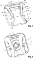
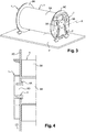
- a winding arrangement of the cable wound on a drum comprises two independent parts as shown in FIGS. Figures 1 and 2 .
- This independent piece 1 made of plastic, for example polypropylene or ABS, has a lower front surface than the circular front surface of each drum flange and carries an articulated support element 2, a rest position, where it is integrated into the corresponding independent part as shown in the Figures 1 and 2 , at an active position, where it comes to rest on the plane supporting the drum and lift it as it will be seen further.
- the independent part 2 has a substantially square front surface inscribed in the circular front surface of the flange of the drum.
- the support element 2 is articulated on the independent part 1, in rotation about an axis A parallel to the plane of this independent part, by one of its ends. It is articulated in rotation on the independent part 1, by the end of two branches 2A, 2B symmetrical with respect to a central transverse plane of the part 1.
- Each branch 2A, 2B has at its other end a foot portion 2A1, 2B1 adapted to land on the plane supporting the drum. These foot parts are connected by a crossbar 2C connecting the two branches 2A, 2B.
- the support element 2 is integrated with the corresponding independent part 1, by full frontal engagement with clipping in a corresponding groove 3A carried by the independent part 1.
- the support element 2 In its deployed active position, it is pivoted about the axis A of its articulation and partially nested with clipping in another groove 3B carried by the independent part 1.
- the independent piece 1 On his other face visible on the figure 2 , the independent piece 1 carries a central pin 4 adapted to be fixed in the central hole of the flange while allowing its rotation, as will be specified below.
- the part 1 also has a through hole 1A.
- the unwinding arrangement of the cable wound on a drum according to the invention comprises two such symmetrical independent pieces intended to be each fixed on a flange of the drum as shown in FIG. figure 3 , where the independent pieces cover each puddle.
- the drum 5 consists of a central cylindrical drum 5A and two circular lateral flanges 5B, 5C. Each independent piece 1, 1 'is fixed on the outer face of each flange 5B, 5C with its pin 4 fixed in the central orifice of each flange while allowing its rotation as visible on the figure 4 .
- the drum 5A is hollow and has a longitudinal cavity 5E open on the central orifice 5D of the flange 5C.
- the pin 4 comprises a clipping element 4A clipped on the inner face of the flange 5C, when the pin 4 is engaged in the central orifice 5D of the flange 5C.
- the pieces will be dimensioned in correspondence.
- the support element 2 is deployed in the active position, by rotation about the axis A of its articulation and it is placed on the plane P supporting the drum and raises the latter.
- the drum 5 is carried on this plane P by the two pieces 1, 1 ' independent and the cable wound on the drum 5A can easily be unwound, the drum 5 can be rotated around the pads 4 to allow this unwinding.
- the Figure 5A represents the support element 2 in detail.
- the foot parts 2A1, 2B1 comprise a rounded edge 2A10, at their front edge adapted to come into contact first with the support plane P. They also have grooves 2A11 on their end face ensuring a hooking on the support plane P or on the ground.
- An independent piece 1, 1 ' is fixed on each of the flanges 5B, 5C of the drum, the support member 2 being in the rest position, where it is integrated with the corresponding independent piece by complete front clipping in the corresponding groove 3A carried by the independent room.
- the drum 5 can then be manipulated independently of these parts 1, 1 ', in particular, it can be moved by rotation on the ground or equivalent.
- the through hole 1A then ensures the possibility of easily grasping the drum 5 in the manner of a handle.
- the support member 2 of each independent piece When it is desired to unwind the cable wound on the drum, the support member 2 of each independent piece is deployed in the active position, where is placed on the plane supporting the drum and raises the latter, this lifting being assisted by the edge rounded 2A10 of each foot portion 2A1, 2B1 and the support member 2 being clipped into the corresponding groove 3B carried by the independent piece.
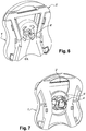
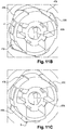
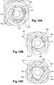
- FIGS. 6 to 12C represent a variant of the invention, wherein the connection of the unwinding arrangement on the flange of a drum is designed differently.
- the independent part 1 ' carries its hinged support member 2', in the rest position, where it is integrated with the corresponding independent part.
- each lug 4 'always has a clipping element 4'A capable of being clipped onto the internal face of each flange, when the cylindrical post 4' of circular section is fitted into the central orifice 5'D of each flange 5 ' B, 5'C represented on the figure 9 .
- the clipping element 4'A is able to be clipped on the internal face of each flange, by means of a key 6 'ensuring the expansion of the clipping arrangement on the inner face of each flange and operable from the outside of the arrangement, by rotation of a ratchet 6'A visible on the figure 6 .
- this key 6 ensures the expansion of the clipping arrangement 4'A on the inner face of each flange, during its rotation, thanks to a radial flange 6'B bearing rounded inclined planes 6'C.
- the key 6 ' also comprises a limit stop 6'D, locking on a hooking portion carried by the unwinding arrangement.
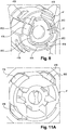
- the tenon 4 ' has meanwhile 4'B radial flanges able to move in at least one groove carried by each flange and directed parallel to the plane of each flange, to allow the rotation of each flange.
- each flange comprises an outer cavity 5'E of frontal shape substantially circumscribed to the section of the tenon 4 'and its radial flanges 4'B and bearing the groove.
- the outer cavity 5'E is of square frontal shape with rounded corners and carries the groove 5'F on its rectilinear sides.
- the tenon 4 ' is introduced from the outside into the orifice 5'F of the flange and it fits with its four radial flanges 4'B in the outer cavity 5'E of frontal square shape with rounded corners.
- the radial flanges 4'B can be introduced and move in the groove 5'F on the rectilinear sides of the outer cavity 5'E, as visible on the figure 11C .
Landscapes
- Storage Of Web-Like Or Filamentary Materials (AREA)
Claims (18)
- Anordnung zum Abrollen eines Kabels auf einer Trommel (5), die aus einer mittleren zylindrischen Walze (5A) und zwei runden seitlichen Flanschen (5B, 5C) besteht, wobei die Anordnung zwei Zapfen (4) umfasst, die ausgelegt sind, um jeweils in eine mittlere Öffnung (5D) jedes Flansches eingefügt zu werden, wobei die Anordnung dadurch gekennzeichnet ist, dass sie lediglich zwei unabhängige Teile umfasst, die jeweils jeden Stift (4) tragen, der ausgelegt ist, um in die mittlere Öffnung (5D) jedes Flansches fixiert zu sein wobei gleichzeitig seine Rotation ermöglicht wird, dadurch, dass die zwei unabhängigen Teile (1, 1') ausgelegt sind, jeden Flansch abzudecken und gleichzeitig eine untere frontale Fläche zur kreisförmigen frontalen Fläche jedes Flansches aufzuweisen, und dadurch, dass jeder unabhängige Teil (1, 1') ein Stützelement (2) aus einer Ruheposition, wo er in den entsprechenden unabhängigen Teil durch komplettes frontales Einführen mit Einrasten in eine entsprechende Nut (3A) integriert ist, der vom unabhängigen Teil (1) getragen wird, in eine aktive Position trägt, wo er auf der Ebene (P) liegt, die die Trommel stützt, und dieses Letztere anhebt.
- Anordnung nach dem vorhergehenden Anspruch, dadurch gekennzeichnet, dass das Sützelement (2) auf dem unabhängigen Teil (1) in Rotation um eine Achse (A), die parallel zur Ebene des unabhängigen Teils ist, durch eines seiner Enden gelenkig verbunden ist.
- Anordnung nach dem vorhergehenden Anspruch, dadurch gekennzeichnet, dass das Stützelement (2) in Rotation auf dem unabhängigen Teil (1) durch das Ende von zwei Armen (2A, 2B) symmetrisch mit Bezug auf eine mittlere Querebene des Stücks gelenkig verbunden ist.
- Anordnung nach dem vorhergehenden Anspruch, dadurch gekennzeichnet, dass der Arm (2A, 2B) an seinem anderen Ende einen Fußteil (2A1, 2B1) umfasst, der ausgelegt ist, um auf der Ebene (P) zu liegen, die die Trommel stützt.
- Anordnung nach dem vorhergehenden Anspruch, dadurch gekennzeichnet, dass die Fußteile (2A1, 2B1) durch eine Querstrebe (2C) verbunden sind, die die zwei Arme verbindet (2A, 2B).
- Anordnung nach Anspruch 4 oder 5, dadurch gekennzeichnet, dass die Fußteile (2A1, 2B1) einen abgerundeten Rand (2A10) an ihrem frontalen Rand umfassen, der ausgelegt ist, um zuerst mit der Stützebene (P) in Kontakt zu kommen.
- Anordnung nach einem der vorhergehenden Ansprüche, dadurch gekennzeichnet, dass jeder Stift (4) ein Einrastelement (4A) umfasst, das ausgelegt ist, um auf der inneren Seite jedes Flansches eingerastet zu sein, wenn der Stift (4) in die mittlere Öffnung (5D) jedes Flansches eingeführt ist.
- Anordnung nach dem vorhergehenden Anspruch, dadurch gekennzeichnet, dass das Einrastelement (4A) ausgelegt ist, um auf der inneren Seite jedes Flansches mit Hilfe eines Schlüssels eingerastet zu sein, der die Erweiterung der Einrastanordnung auf der inneren Seite jedes Flansches sicherstellt und von der Außenseite der Anordnung betätigt werden kann.
- Anordnung nach dem vorhergehenden Anspruch, dadurch gekennzeichnet, dass der Schlüssel die Erweiterung der Einrastanordnung auf der inneren Seite jedes Flansches bei seiner Rotation dank eines radialen Bügels sicherstellt, der die geneigten Ebenen trägt.
- Anordnung nach dem vorhergehenden Anspruch, dadurch gekennzeichnet, dass die geneigten Ebenen abgerundet sind.
- Anordnung nach Anspruch 9 oder 10, dadurch gekennzeichnet, dass der Schlüssel einen Anschlag in der Endlage zur Blockierung auf einem Befestigungsteil umfasst, der von der Anordnung getragen wird.
- Anordnung nach einem der vorhergehenden Ansprüche, dadurch gekennzeichnet, dass jeder unabhängige Teil (1, 1') eine frontale Fläche aufweist, die in die runde frontale Fläche jedes Flansches (5B, 5C) eingeschrieben ist.
- Anordnung nach dem vorhergehenden Anspruch, dadurch gekennzeichnet, dass jeder unabhängige Teil (1, 1') eine im Wesentlichen quadratische frontale Fläche aufweist.
- Anordnung nach einem der vorhergehenden Ansprüche, dadurch gekennzeichnet, dass jeder Stift (4) zylindrisch mit rundem Schnitt ist, der ausgelegt ist, um in die mittlere Öffnung (5D) jedes Flansches eingeführt zu sein.
- Anordnung nach dem vorhergehenden Anspruch, dadurch gekennzeichnet, dass jeder Stift (4) radiale Bügel umfasst, die ausgelegt sind, um sich wenigstens in einer Nut zu verschieben, die von jedem Flansch getragen wirdund parallel zur Ebene jedes Flansches ausgerichtet ist, um die Rotation jedes Flansches zu ermöglichen.
- Kabeltrommel umfassend eine Anordnung nach einem der vorhergehenden Ansprüche, wobei ein unabhängiger Teil (1, 1') auf jeden seiner Flansche (5B, 5C) fixiert ist.
- Kabeltrommel, umfassend eine Anordnung nach Anspruch 15, dadurch gekennzeichnet, dass die mittlere Öffnung (5D) jedes Flansches einen äußeren Hohlraum mit einer frontalen Form umfasst, die im Wesentlichen dem Schnitt des Stifts und seiner radialen Bügel umschrieben ist und die Nut trägt.
- Trommel nach dem vorhergehenden Anspruch, dadurch gekennzeichnet, dass der äußere Hohlraum eine quaratische frontale Form mit abgerundeten Ecken aufweist und die Nut auf geradlinigen Seiten trägt.
Applications Claiming Priority (1)
| Application Number | Priority Date | Filing Date | Title |
|---|---|---|---|
| FR1661981A FR3059656B1 (fr) | 2016-12-06 | 2016-12-06 | Agencement de deroulement du cable enroule sur un touret |
Publications (2)
| Publication Number | Publication Date |
|---|---|
| EP3333107A1 EP3333107A1 (de) | 2018-06-13 |
| EP3333107B1 true EP3333107B1 (de) | 2019-07-24 |
Family
ID=57861138
Family Applications (1)
| Application Number | Title | Priority Date | Filing Date |
|---|---|---|---|
| EP17191966.5A Active EP3333107B1 (de) | 2016-12-06 | 2017-09-19 | Anordnung zum abrollen eines auf einer trommel aufgerollten kabels |
Country Status (4)
| Country | Link |
|---|---|
| EP (1) | EP3333107B1 (de) |
| ES (1) | ES2746854T3 (de) |
| FR (1) | FR3059656B1 (de) |
| PT (1) | PT3333107T (de) |
Cited By (1)
| Publication number | Priority date | Publication date | Assignee | Title |
|---|---|---|---|---|
| EP3964466A1 (de) | 2020-09-08 | 2022-03-09 | Nexans | Vorrichtung zum abwickeln eines auf eine spule aufgewickelten kabels |
Families Citing this family (2)
| Publication number | Priority date | Publication date | Assignee | Title |
|---|---|---|---|---|
| CN109775451B (zh) * | 2019-01-16 | 2023-10-03 | 浙江凯成智能设备股份有限公司 | 一种空气变形丝机 |
| US12221313B2 (en) * | 2022-02-28 | 2025-02-11 | Leviton Manufacturing Co., Inc. | Interlocked pay off reel design |
Family Cites Families (5)
| Publication number | Priority date | Publication date | Assignee | Title |
|---|---|---|---|---|
| JPS61229780A (ja) * | 1985-04-03 | 1986-10-14 | Nippon Atom Ind Group Co Ltd | ケ−ブルドラム |
| ATE110690T1 (de) * | 1989-06-09 | 1994-09-15 | Katimex Cielker Gmbh | Vorrichtung zum anheben einer kabeltrommel. |
| SE463919B (sv) | 1990-03-30 | 1991-02-11 | Maillefer Nokia Holding | Anordning vid en automatisk kabelspolare, innefattande rotationsanordning och hoejdavkaenningsorgan foer kabeltrumman |
| US7077368B1 (en) * | 2003-06-30 | 2006-07-18 | John Karoly | Spindle support stand |
| US9731921B2 (en) * | 2014-07-02 | 2017-08-15 | The Boeing Company | Web roll handling and loading system |
-
2016
- 2016-12-06 FR FR1661981A patent/FR3059656B1/fr not_active Expired - Fee Related
-
2017
- 2017-09-19 EP EP17191966.5A patent/EP3333107B1/de active Active
- 2017-09-19 ES ES17191966T patent/ES2746854T3/es active Active
- 2017-09-19 PT PT171919665T patent/PT3333107T/pt unknown
Non-Patent Citations (1)
| Title |
|---|
| None * |
Cited By (1)
| Publication number | Priority date | Publication date | Assignee | Title |
|---|---|---|---|---|
| EP3964466A1 (de) | 2020-09-08 | 2022-03-09 | Nexans | Vorrichtung zum abwickeln eines auf eine spule aufgewickelten kabels |
Also Published As
| Publication number | Publication date |
|---|---|
| EP3333107A1 (de) | 2018-06-13 |
| FR3059656B1 (fr) | 2019-06-07 |
| PT3333107T (pt) | 2019-10-31 |
| FR3059656A1 (fr) | 2018-06-08 |
| ES2746854T3 (es) | 2020-03-09 |
Similar Documents
| Publication | Publication Date | Title |
|---|---|---|
| FR2783737A1 (fr) | Dispositif de serrage et desserrage de sangle | |
| FR3004739A3 (fr) | Ensemble d'ancrage | |
| EP3333107A1 (de) | Anordnung zum abrollen eines auf einer trommel aufgerollten kabels | |
| EP0219385A2 (de) | Papierkorb | |
| FR2756792A1 (fr) | Cale amovible pour l'immobilisation d'une roue d'un vehicule sur une structure porteuse perforee | |
| EP0216683B1 (de) | Ein Magazin bildendes Werkzeug zum Anbringen irgend eines Artikels, insbesondere für Verkabelungskennzeichnungen | |
| FR2467115A1 (fr) | Dispositif d'arrimage d'objets divers, notamment sacs et valises dans un coffre de vehicule | |
| EP3025054B1 (de) | Segmentierte windturbinenschaufel mit einer montagevorrichtung | |
| EP0807730B1 (de) | Vorrichtung die den Zugang zu einer bestimmten gesicherten Zone erlaubt | |
| EP0366571A1 (de) | Fahrzeugfestlegeeinrichtung auf dem Boden von Anhängern oder von Eisenbahnwagen oder dergleichen | |
| WO1985000328A1 (fr) | Essuie-glace comportant un axe d'articulation du balai sur le bras a verrouillage transversal | |
| EP1319586B1 (de) | Unterbodenbefestigung für ein Kraftfahrzeugersatzrad | |
| EP0322299B1 (de) | Halterung für ein Reserverad eines Kraftfahrzeuges | |
| EP1183434B1 (de) | Vorrichtung zur verriegelung eines abdeckelementes auf einem stützrahmen | |
| FR2960228A1 (fr) | Dispositif a manivelle pour enrouler les sangles de transport | |
| FR2597920A1 (fr) | Dispositif permettant d'accrocher et de deplacer une echelle sur un toit, et echelle munie de ses elements | |
| EP3512742B1 (de) | Vorrichtung zur befestigung einer leiter am fahrzeugdach | |
| FR3012013A1 (fr) | Rouleau a deboiter | |
| FR2781383A1 (fr) | Perfectionnement pour dispositif de support de devidoir mobile de tuyau | |
| FR3106354A1 (fr) | Abri repliable de type tonnelle pliante | |
| EP1716832B1 (de) | Verbesserte Tragbahre | |
| FR2792302A1 (fr) | Dispositif enrouleur de sangle | |
| FR3140895A1 (fr) | Dispositif de verrouillage d’une table de coffrage sur une fourche de translation | |
| WO2002032710A1 (fr) | Dispositif demontable et transportable pour l"enroulement et le deroulement d"un element couvrant de protection au-dessus d"une benne ou conteneur | |
| FR2850639A1 (fr) | Bac de collecte de dechets equipe de tourillons de prehension pour un dispositif de levage, de convoyage et/ou de guidage |
Legal Events
| Date | Code | Title | Description |
|---|---|---|---|
| PUAI | Public reference made under article 153(3) epc to a published international application that has entered the european phase |
Free format text: ORIGINAL CODE: 0009012 |
|
| STAA | Information on the status of an ep patent application or granted ep patent |
Free format text: STATUS: THE APPLICATION HAS BEEN PUBLISHED |
|
| AK | Designated contracting states |
Kind code of ref document: A1 Designated state(s): AL AT BE BG CH CY CZ DE DK EE ES FI FR GB GR HR HU IE IS IT LI LT LU LV MC MK MT NL NO PL PT RO RS SE SI SK SM TR |
|
| AX | Request for extension of the european patent |
Extension state: BA ME |
|
| STAA | Information on the status of an ep patent application or granted ep patent |
Free format text: STATUS: REQUEST FOR EXAMINATION WAS MADE |
|
| 17P | Request for examination filed |
Effective date: 20181213 |
|
| RBV | Designated contracting states (corrected) |
Designated state(s): AL AT BE BG CH CY CZ DE DK EE ES FI FR GB GR HR HU IE IS IT LI LT LU LV MC MK MT NL NO PL PT RO RS SE SI SK SM TR |
|
| GRAP | Despatch of communication of intention to grant a patent |
Free format text: ORIGINAL CODE: EPIDOSNIGR1 |
|
| STAA | Information on the status of an ep patent application or granted ep patent |
Free format text: STATUS: GRANT OF PATENT IS INTENDED |
|
| INTG | Intention to grant announced |
Effective date: 20190222 |
|
| GRAS | Grant fee paid |
Free format text: ORIGINAL CODE: EPIDOSNIGR3 |
|
| GRAA | (expected) grant |
Free format text: ORIGINAL CODE: 0009210 |
|
| STAA | Information on the status of an ep patent application or granted ep patent |
Free format text: STATUS: THE PATENT HAS BEEN GRANTED |
|
| AK | Designated contracting states |
Kind code of ref document: B1 Designated state(s): AL AT BE BG CH CY CZ DE DK EE ES FI FR GB GR HR HU IE IS IT LI LT LU LV MC MK MT NL NO PL PT RO RS SE SI SK SM TR |
|
| REG | Reference to a national code |
Ref country code: GB Ref legal event code: FG4D Free format text: NOT ENGLISH |
|
| REG | Reference to a national code |
Ref country code: CH Ref legal event code: EP |
|
| REG | Reference to a national code |
Ref country code: DE Ref legal event code: R096 Ref document number: 602017005490 Country of ref document: DE |
|
| REG | Reference to a national code |
Ref country code: AT Ref legal event code: REF Ref document number: 1157928 Country of ref document: AT Kind code of ref document: T Effective date: 20190815 |
|
| REG | Reference to a national code |
Ref country code: IE Ref legal event code: FG4D Free format text: LANGUAGE OF EP DOCUMENT: FRENCH |
|
| REG | Reference to a national code |
Ref country code: SE Ref legal event code: TRGR |
|
| REG | Reference to a national code |
Ref country code: NL Ref legal event code: FP |
|
| REG | Reference to a national code |
Ref country code: PT Ref legal event code: SC4A Ref document number: 3333107 Country of ref document: PT Date of ref document: 20191031 Kind code of ref document: T Free format text: AVAILABILITY OF NATIONAL TRANSLATION Effective date: 20191022 |
|
| REG | Reference to a national code |
Ref country code: NO Ref legal event code: T2 Effective date: 20190724 |
|
| REG | Reference to a national code |
Ref country code: LT Ref legal event code: MG4D |
|
| REG | Reference to a national code |
Ref country code: AT Ref legal event code: MK05 Ref document number: 1157928 Country of ref document: AT Kind code of ref document: T Effective date: 20190724 |
|
| PG25 | Lapsed in a contracting state [announced via postgrant information from national office to epo] |
Ref country code: FI Free format text: LAPSE BECAUSE OF FAILURE TO SUBMIT A TRANSLATION OF THE DESCRIPTION OR TO PAY THE FEE WITHIN THE PRESCRIBED TIME-LIMIT Effective date: 20190724 Ref country code: LT Free format text: LAPSE BECAUSE OF FAILURE TO SUBMIT A TRANSLATION OF THE DESCRIPTION OR TO PAY THE FEE WITHIN THE PRESCRIBED TIME-LIMIT Effective date: 20190724 Ref country code: AT Free format text: LAPSE BECAUSE OF FAILURE TO SUBMIT A TRANSLATION OF THE DESCRIPTION OR TO PAY THE FEE WITHIN THE PRESCRIBED TIME-LIMIT Effective date: 20190724 Ref country code: BG Free format text: LAPSE BECAUSE OF FAILURE TO SUBMIT A TRANSLATION OF THE DESCRIPTION OR TO PAY THE FEE WITHIN THE PRESCRIBED TIME-LIMIT Effective date: 20191024 Ref country code: HR Free format text: LAPSE BECAUSE OF FAILURE TO SUBMIT A TRANSLATION OF THE DESCRIPTION OR TO PAY THE FEE WITHIN THE PRESCRIBED TIME-LIMIT Effective date: 20190724 |
|
| PG25 | Lapsed in a contracting state [announced via postgrant information from national office to epo] |
Ref country code: RS Free format text: LAPSE BECAUSE OF FAILURE TO SUBMIT A TRANSLATION OF THE DESCRIPTION OR TO PAY THE FEE WITHIN THE PRESCRIBED TIME-LIMIT Effective date: 20190724 Ref country code: IS Free format text: LAPSE BECAUSE OF FAILURE TO SUBMIT A TRANSLATION OF THE DESCRIPTION OR TO PAY THE FEE WITHIN THE PRESCRIBED TIME-LIMIT Effective date: 20191124 Ref country code: LV Free format text: LAPSE BECAUSE OF FAILURE TO SUBMIT A TRANSLATION OF THE DESCRIPTION OR TO PAY THE FEE WITHIN THE PRESCRIBED TIME-LIMIT Effective date: 20190724 Ref country code: AL Free format text: LAPSE BECAUSE OF FAILURE TO SUBMIT A TRANSLATION OF THE DESCRIPTION OR TO PAY THE FEE WITHIN THE PRESCRIBED TIME-LIMIT Effective date: 20190724 |
|
| REG | Reference to a national code |
Ref country code: GR Ref legal event code: EP Ref document number: 20190403265 Country of ref document: GR Effective date: 20200213 |
|
| REG | Reference to a national code |
Ref country code: ES Ref legal event code: FG2A Ref document number: 2746854 Country of ref document: ES Kind code of ref document: T3 Effective date: 20200309 |
|
| REG | Reference to a national code |
Ref country code: DE Ref legal event code: R119 Ref document number: 602017005490 Country of ref document: DE |
|
| PG25 | Lapsed in a contracting state [announced via postgrant information from national office to epo] |
Ref country code: EE Free format text: LAPSE BECAUSE OF FAILURE TO SUBMIT A TRANSLATION OF THE DESCRIPTION OR TO PAY THE FEE WITHIN THE PRESCRIBED TIME-LIMIT Effective date: 20190724 Ref country code: PL Free format text: LAPSE BECAUSE OF FAILURE TO SUBMIT A TRANSLATION OF THE DESCRIPTION OR TO PAY THE FEE WITHIN THE PRESCRIBED TIME-LIMIT Effective date: 20190724 Ref country code: DK Free format text: LAPSE BECAUSE OF FAILURE TO SUBMIT A TRANSLATION OF THE DESCRIPTION OR TO PAY THE FEE WITHIN THE PRESCRIBED TIME-LIMIT Effective date: 20190724 Ref country code: RO Free format text: LAPSE BECAUSE OF FAILURE TO SUBMIT A TRANSLATION OF THE DESCRIPTION OR TO PAY THE FEE WITHIN THE PRESCRIBED TIME-LIMIT Effective date: 20190724 |
|
| PG25 | Lapsed in a contracting state [announced via postgrant information from national office to epo] |
Ref country code: SK Free format text: LAPSE BECAUSE OF FAILURE TO SUBMIT A TRANSLATION OF THE DESCRIPTION OR TO PAY THE FEE WITHIN THE PRESCRIBED TIME-LIMIT Effective date: 20190724 Ref country code: CZ Free format text: LAPSE BECAUSE OF FAILURE TO SUBMIT A TRANSLATION OF THE DESCRIPTION OR TO PAY THE FEE WITHIN THE PRESCRIBED TIME-LIMIT Effective date: 20190724 Ref country code: MC Free format text: LAPSE BECAUSE OF FAILURE TO SUBMIT A TRANSLATION OF THE DESCRIPTION OR TO PAY THE FEE WITHIN THE PRESCRIBED TIME-LIMIT Effective date: 20190724 Ref country code: IS Free format text: LAPSE BECAUSE OF FAILURE TO SUBMIT A TRANSLATION OF THE DESCRIPTION OR TO PAY THE FEE WITHIN THE PRESCRIBED TIME-LIMIT Effective date: 20200224 Ref country code: SM Free format text: LAPSE BECAUSE OF FAILURE TO SUBMIT A TRANSLATION OF THE DESCRIPTION OR TO PAY THE FEE WITHIN THE PRESCRIBED TIME-LIMIT Effective date: 20190724 |
|
| PLBE | No opposition filed within time limit |
Free format text: ORIGINAL CODE: 0009261 |
|
| STAA | Information on the status of an ep patent application or granted ep patent |
Free format text: STATUS: NO OPPOSITION FILED WITHIN TIME LIMIT |
|
| PG2D | Information on lapse in contracting state deleted |
Ref country code: IS |
|
| PG25 | Lapsed in a contracting state [announced via postgrant information from national office to epo] |
Ref country code: DE Free format text: LAPSE BECAUSE OF NON-PAYMENT OF DUE FEES Effective date: 20200401 Ref country code: IE Free format text: LAPSE BECAUSE OF NON-PAYMENT OF DUE FEES Effective date: 20190919 Ref country code: LU Free format text: LAPSE BECAUSE OF NON-PAYMENT OF DUE FEES Effective date: 20190919 |
|
| 26N | No opposition filed |
Effective date: 20200603 |
|
| PG25 | Lapsed in a contracting state [announced via postgrant information from national office to epo] |
Ref country code: SI Free format text: LAPSE BECAUSE OF FAILURE TO SUBMIT A TRANSLATION OF THE DESCRIPTION OR TO PAY THE FEE WITHIN THE PRESCRIBED TIME-LIMIT Effective date: 20190724 |
|
| REG | Reference to a national code |
Ref country code: CH Ref legal event code: PL |
|
| PG25 | Lapsed in a contracting state [announced via postgrant information from national office to epo] |
Ref country code: CY Free format text: LAPSE BECAUSE OF FAILURE TO SUBMIT A TRANSLATION OF THE DESCRIPTION OR TO PAY THE FEE WITHIN THE PRESCRIBED TIME-LIMIT Effective date: 20190724 |
|
| PG25 | Lapsed in a contracting state [announced via postgrant information from national office to epo] |
Ref country code: MT Free format text: LAPSE BECAUSE OF FAILURE TO SUBMIT A TRANSLATION OF THE DESCRIPTION OR TO PAY THE FEE WITHIN THE PRESCRIBED TIME-LIMIT Effective date: 20190724 Ref country code: HU Free format text: LAPSE BECAUSE OF FAILURE TO SUBMIT A TRANSLATION OF THE DESCRIPTION OR TO PAY THE FEE WITHIN THE PRESCRIBED TIME-LIMIT; INVALID AB INITIO Effective date: 20170919 |
|
| PG25 | Lapsed in a contracting state [announced via postgrant information from national office to epo] |
Ref country code: LI Free format text: LAPSE BECAUSE OF NON-PAYMENT OF DUE FEES Effective date: 20200930 Ref country code: CH Free format text: LAPSE BECAUSE OF NON-PAYMENT OF DUE FEES Effective date: 20200930 |
|
| GBPC | Gb: european patent ceased through non-payment of renewal fee |
Effective date: 20210919 |
|
| PG25 | Lapsed in a contracting state [announced via postgrant information from national office to epo] |
Ref country code: MK Free format text: LAPSE BECAUSE OF FAILURE TO SUBMIT A TRANSLATION OF THE DESCRIPTION OR TO PAY THE FEE WITHIN THE PRESCRIBED TIME-LIMIT Effective date: 20190724 |
|
| PG25 | Lapsed in a contracting state [announced via postgrant information from national office to epo] |
Ref country code: GB Free format text: LAPSE BECAUSE OF NON-PAYMENT OF DUE FEES Effective date: 20210919 |
|
| PGFP | Annual fee paid to national office [announced via postgrant information from national office to epo] |
Ref country code: GR Payment date: 20230921 Year of fee payment: 7 |
|
| PG25 | Lapsed in a contracting state [announced via postgrant information from national office to epo] |
Ref country code: GR Free format text: LAPSE BECAUSE OF NON-PAYMENT OF DUE FEES Effective date: 20250407 |
|
| PGFP | Annual fee paid to national office [announced via postgrant information from national office to epo] |
Ref country code: PT Payment date: 20250911 Year of fee payment: 9 |
|
| PGFP | Annual fee paid to national office [announced via postgrant information from national office to epo] |
Ref country code: NO Payment date: 20250923 Year of fee payment: 9 |
|
| PGFP | Annual fee paid to national office [announced via postgrant information from national office to epo] |
Ref country code: TR Payment date: 20250915 Year of fee payment: 9 Ref country code: IT Payment date: 20250923 Year of fee payment: 9 Ref country code: NL Payment date: 20250918 Year of fee payment: 9 |
|
| PGFP | Annual fee paid to national office [announced via postgrant information from national office to epo] |
Ref country code: BE Payment date: 20250918 Year of fee payment: 9 |
|
| PGFP | Annual fee paid to national office [announced via postgrant information from national office to epo] |
Ref country code: FR Payment date: 20250922 Year of fee payment: 9 |
|
| PGFP | Annual fee paid to national office [announced via postgrant information from national office to epo] |
Ref country code: SE Payment date: 20250918 Year of fee payment: 9 |
|
| PGFP | Annual fee paid to national office [announced via postgrant information from national office to epo] |
Ref country code: ES Payment date: 20251028 Year of fee payment: 9 |