EP3333007B1 - Pantograph wearing strip for railway vehicle - Google Patents
Pantograph wearing strip for railway vehicle Download PDFInfo
- Publication number
- EP3333007B1 EP3333007B1 EP17204665.8A EP17204665A EP3333007B1 EP 3333007 B1 EP3333007 B1 EP 3333007B1 EP 17204665 A EP17204665 A EP 17204665A EP 3333007 B1 EP3333007 B1 EP 3333007B1
- Authority
- EP
- European Patent Office
- Prior art keywords
- metal insert
- collector support
- longitudinal extension
- electricity
- support
- Prior art date
- Legal status (The legal status is an assumption and is not a legal conclusion. Google has not performed a legal analysis and makes no representation as to the accuracy of the status listed.)
- Active
Links
- 229910052751 metal Inorganic materials 0.000 claims description 156
- 239000002184 metal Substances 0.000 claims description 156
- 230000005611 electricity Effects 0.000 claims description 127
- OKTJSMMVPCPJKN-UHFFFAOYSA-N Carbon Chemical compound [C] OKTJSMMVPCPJKN-UHFFFAOYSA-N 0.000 claims description 66
- 229910052799 carbon Inorganic materials 0.000 claims description 66
- 230000000295 complement effect Effects 0.000 claims description 3
- 210000002105 tongue Anatomy 0.000 description 58
- 230000005489 elastic deformation Effects 0.000 description 6
- 238000010438 heat treatment Methods 0.000 description 4
- 229910001018 Cast iron Inorganic materials 0.000 description 2
- 229910052782 aluminium Inorganic materials 0.000 description 2
- XAGFODPZIPBFFR-UHFFFAOYSA-N aluminium Chemical compound [Al] XAGFODPZIPBFFR-UHFFFAOYSA-N 0.000 description 2
- OKTJSMMVPCPJKN-BJUDXGSMSA-N carbon-11 Chemical compound [11C] OKTJSMMVPCPJKN-BJUDXGSMSA-N 0.000 description 2
- 230000000694 effects Effects 0.000 description 2
- 239000003292 glue Substances 0.000 description 2
- 238000003780 insertion Methods 0.000 description 2
- 230000037431 insertion Effects 0.000 description 2
- 238000004519 manufacturing process Methods 0.000 description 2
- 230000036961 partial effect Effects 0.000 description 2
- 238000013519 translation Methods 0.000 description 2
- 241000826860 Trapezium Species 0.000 description 1
- 239000000853 adhesive Substances 0.000 description 1
- 230000001070 adhesive effect Effects 0.000 description 1
- 239000012298 atmosphere Substances 0.000 description 1
- 230000008901 benefit Effects 0.000 description 1
- 238000005266 casting Methods 0.000 description 1
- 239000004020 conductor Substances 0.000 description 1
- 238000002788 crimping Methods 0.000 description 1
- 230000006866 deterioration Effects 0.000 description 1
- 230000001976 improved effect Effects 0.000 description 1
- 230000000670 limiting effect Effects 0.000 description 1
- 230000009021 linear effect Effects 0.000 description 1
- 238000003754 machining Methods 0.000 description 1
- 230000014759 maintenance of location Effects 0.000 description 1
- 239000000463 material Substances 0.000 description 1
- 238000000034 method Methods 0.000 description 1
- 238000000465 moulding Methods 0.000 description 1
- 229920003023 plastic Polymers 0.000 description 1
- 239000004033 plastic Substances 0.000 description 1
- 230000008569 process Effects 0.000 description 1
- 230000001737 promoting effect Effects 0.000 description 1
- 238000000926 separation method Methods 0.000 description 1
- 238000010008 shearing Methods 0.000 description 1
- 238000003892 spreading Methods 0.000 description 1
- 230000007480 spreading Effects 0.000 description 1
Images


Classifications
-
- B—PERFORMING OPERATIONS; TRANSPORTING
- B60—VEHICLES IN GENERAL
- B60L—PROPULSION OF ELECTRICALLY-PROPELLED VEHICLES; SUPPLYING ELECTRIC POWER FOR AUXILIARY EQUIPMENT OF ELECTRICALLY-PROPELLED VEHICLES; ELECTRODYNAMIC BRAKE SYSTEMS FOR VEHICLES IN GENERAL; MAGNETIC SUSPENSION OR LEVITATION FOR VEHICLES; MONITORING OPERATING VARIABLES OF ELECTRICALLY-PROPELLED VEHICLES; ELECTRIC SAFETY DEVICES FOR ELECTRICALLY-PROPELLED VEHICLES
- B60L5/00—Current collectors for power supply lines of electrically-propelled vehicles
- B60L5/18—Current collectors for power supply lines of electrically-propelled vehicles using bow-type collectors in contact with trolley wire
- B60L5/20—Details of contact bow
- B60L5/205—Details of contact bow with carbon contact members
Definitions
- the invention relates to a friction strip for a pantograph of a railway vehicle, such as a train or a tram.
- a catenary conventionally comprises a horizontal carrying cable on which is suspended a horizontal contact wire in which the electric power current flows and through which the pantograph captures the electric power current.
- the pantograph comprises a bow comprising one or more friction bands extending parallel to a direction of longitudinal, horizontal extension and generally orthogonal to the direction in which the rail vehicle moves and an electricity collector support to which is assembled the friction strip.
- the friction strip is provided for rubbing the catenary, in particular the contact wire, so as to capture the current of electrical supply.
- the large dimension of the friction strip in the direction of longitudinal extension makes it possible to absorb the zigzag of the catenary and the movements of the railway vehicle like the catenary in said direction of longitudinal extension.
- the small dimension of the friction strip in a transverse direction, horizontal and orthogonal to the direction of longitudinal extension allows a linear contact to be made between the friction strip and the contact wire, thus ensuring the passage of the current d power supply of the contact wire from the catenary to the friction strip and therefore to the railway vehicle.
- the electric current flowing through the friction strip may amount to more than 1000 A, thereby causing problems with the heating of the friction strip.
- the metallic insert which is more conductive than the friction strip, for example made of carbon, deflects part of the electric current, so as to reduce the amount of electric current flowing through the friction strip and thus limit their heating.
- the document FR 1 110 518 A describes an example of a friction strip in which the electricity collector support and the metal insert are assembled by screwing.
- This solution requires the use of small screws which are fragile.
- this solution lacks reliability in the sense that it is necessary to tighten the screws so that the current flows, which reduces the freedom of sliding which is necessary to compensate for the differential thermal expansions between the electricity collector support and the metal insert. .
- the document DE 10 2010 042 027 A1 describes another example of a friction strip with a metal insert.
- the metal insert generally comprises a U shape, the branches of which alternately have discontinuities.
- the metal insert is also fixed to the electricity collector support at the core of said U by means of a plurality of screws. This solution is complicated and costly to implement.
- the object of the present invention is to overcome the drawbacks mentioned above, in particular by proposing a friction strip for a pantograph of a railway vehicle having a shorter assembly time, a cost of lower manufacturing and a more robust assembly quality while ensuring good control of the passage of electric current between the carbon strips, the metal insert and the electricity collector support.
- the present invention also relates to a metal insert for a friction strip as previously described.
- the present invention also relates to an electricity collector support for a friction strip as previously described.
- the present invention also relates to a pantograph bow comprising at least one friction strip as previously described.
- the present invention further relates to a pantograph for a railway vehicle comprising a bow comprising at least one friction strip as previously described.
- the Figures 1 to 7 show a friction strip 10 for a pantograph bow (not shown) of a rail vehicle (not shown), in particular of a train or a tram, according to a first embodiment of the invention .
- the Figures 8 to 12 show a friction strip 10A for a rail vehicle pantograph according to a second embodiment of the invention.
- the figures 13 to 16 show a friction strip 10B for a rail vehicle pantograph according to a third embodiment of the invention.
- the common elements between these different embodiments have the same references.
- An orthogonal coordinate system comprising a direction of longitudinal extension X, a transverse direction Y and a vertical direction Z. It will be noted that the transverse direction Y corresponds to the direction in which the rail vehicle moves.
- a plane P X comprising the direction of longitudinal extension X is further defined.
- the plane P X is for example defined by the direction of longitudinal extension X and by the vertical direction Z.
- the metal insert 13 can be arranged in contact with the first carbon strip 11 on the one hand and the second carbon strip 12 on the other hand.
- the metal insert 13 can also be formed with clearance between the first and second strips 11, 12 of carbon.
- the electricity collector support 14 is made from an electrically conductive material.
- the electricity collecting support 14 may be metallic. It can in particular be made from aluminum.
- the electricity collecting support 14 and / or the metal insert 13 comprise elastic interlocking means 18, 35, 39 cooperating with the metal insert 13 and / or the electricity collecting support 14, so as to ensure the assembly of the metal insert 13 to the electricity collector support 14 ( figures 2 , 9, 10 and 11 ) and the passage of electric current between the metal insert 13 and the electricity collecting support 14 via said elastic interlocking means 18, 35, 39.
- the metal insert 13 is assembled to the electricity collecting support 14 by elastic interlocking.
- Such an assembly by elastic interlocking is more industrial. It in fact makes it possible to limit the time necessary for assembling the metal insert 13 and the electricity collector support 14. Furthermore, it represents a low manufacturing cost for the metal insert 13 and the collector support. electricity 14. Finally, it ensures a robust assembly between the metal insert 13 and the electricity collector support 14. It imposes a contact between the metal insert 13 and the electricity collector support 14 which guarantees good control of the passage electrical current between the metal insert 13 and the electricity collecting support 14. This assembly also allows differential thermal expansion between the metal insert 13 and the electricity collecting support 14.
- the Figures 1 to 7 show the friction strip 10 according to the first embodiment of the invention.
- the electricity collector support 14 extends parallel to the direction of longitudinal extension X ( figure 1 ).
- the electricity collector support 14 is shown in more detail in the figure 7 .
- the electricity collector support 14 comprises a lower wall 15 and an upper wall 16 in the vertical direction Z.
- the upper wall 16 is arranged opposite the first and second strips 11, 12 of carbon and the metal insert 13.
- the lower 15 and upper 16 walls are for example connected to each other via a plurality of side walls 17a, 17b.
- the side walls 17a, 17b can be vertical (parallel to the plane P x ) or slightly inclined relative to the plane P x , for example up to 10 °.
- the electricity collector support 14 comprises two first side walls 17a arranged on either side of the plane P X and connecting between them longitudinal edges of the lower 15 and upper walls 16.
- the electricity collector support 14 comprises further two second side walls 17b also arranged on either side of the plane P X and each connecting the bottom wall 15 and the top wall 16 between one of the first side walls 17a and the plane P X.
- the upper wall 16 of the electricity collector support 14 comprises a pair of elastically deformable tongues 18 extending from the upper wall 16 facing each other and together defining a space 19 accommodating the metal insert 13 ( figure 7 ).
- the tongues 18 ensure the assembly of the metal insert 13 to the electricity collector support 14 by elastic fitting ( figures 2 and 3 ).
- the metal insert 13 is forcibly inserted between the tongues 18 in the space 19, the tongues 18 moving apart. one relative to the other by elastic deformation as the metal insert 13 sinks into the space 19.
- the elastic deformation of said tongues 18 tends to exert a elastic return force towards the metal insert 13, enclosing the latter and thus ensuring the assembly of the metal insert 13 to the electricity collector support 14 ( figure 3 ).
- the metal insert 13 is for example inserted by force by means of a press.
- the contact between the tongues 18 and the metal insert 13 ensures the passage of electric current between the metal insert 13 and the electricity collecting support 14.
- the tongues 18 extend for example from the upper wall 16, generally parallel to the plane P x .
- the tongues 18 are arranged on either side of the plane P x .
- Each of the tongues 18 further comprises an elastically and plastically deformable tooth 20 extending from a free end 21 of said tongue 18, in the space 19 defined between the pair of tongues 18 and accommodating the metal insert 13 ( figures 2, 3 and 7 ).
- the teeth 20 of the tongues 18 extend from the free end 21 of said tongues 18 in the direction of one another.
- the teeth 20 cooperate with the metal insert 13.
- the tongues 18 and the teeth 20 together ensure the assembly of the metal insert 13 to the electricity collector support 14 by elastic interlocking.
- the teeth 20 partially retain their elastic property in contact with the metal insert 13.
- the tongues 18 deform elastically as the metal insert 13 is introduced into the space 19, spreading the one with respect to the other, while the teeth 20 are partially crushed by the metal insert 13.
- the elastic deformation of said tongues 18 and the partial crushing of the teeth 20 together tend to exert an elastic return force in the direction of the metal insert 13, enclosing the latter and thus ensuring the assembly of the metal insert 13 to the electricity collector support 14 ( figure 3 ).
- the tightening of the tongues 18 and more precisely of their teeth 20 against the metal insert 13 ensures the passage of the electric current between the metal insert 13 and the electricity collecting support 14.
- the passage of the electric current is further improved by the teeth 20 of the tongues 18 which have been slightly blunted by the forceful passage of the metal insert 13 and thus increase the contact surface between the metal insert 13 and the electricity collector support 14 ( figure 3 ).
- the metal insert 13 retains a freedom of sliding in the direction of longitudinal extension X relative to the electricity collector support 14 making it possible to compensate for any difference in thermal expansion between the metal insert 13 and the collector support electricity 14. This is particularly the case, when the metal insert 13 and the electricity collector support 14 are made from a different material.
- the metal insert 13 is for example made from of cast iron, while the electricity collector support 14 is for example made from aluminum.
- the metal insert 13 has a generally parallelepiped shape, in particular a generally straight block shape.
- the metal insert 13 is shown in more detail on the figure 5 .
- the metal insert 13 comprises a lower portion and an upper portion in the vertical direction Z.
- the lower portion is arranged opposite the upper wall 16 of the electricity collecting support 14.
- the lower portion of the metal insert 13 comprises for example at least one opening 27 of elongated shape extending in the direction of longitudinal extension X ( figure 5 ).
- the opening or openings 27 engage with the teeth 20 of the tongues 18 of the electricity collecting support 14, so as to block the metal insert 13 in translation in the vertical direction Z in a direction opposite to the electricity collecting support 14 (( figure 2 ).
- the teeth 20 each form a stop which, when it cooperates with an opening 27, prevents the metal insert 13 from being withdrawn from the space 19 of the collector support d electricity 14.
- the openings 27 are for example produced by oxycutting, in particular when the metal insert 13 is produced from sheet metal.
- the openings 27 can alternatively be made during the molding of the metal insert 13, in particular when the metal insert 13 is made from cast iron.
- the opening or openings 27 may be replaced by one or more grooves extending on either side of the plane P x , parallel to the direction of longitudinal extension X ( figure 5 ).
- the metal insert 13 can be produced in several sections distributed in the longitudinal direction X and assembled with the same electricity collector support 14. In this case, a slight clearance can be provided in the direction of extension longitudinal X between the sections of the metal insert 13, in order to reduce the stresses due to the expansion of each of the sections. This variant is shown on the figure 6 .
- the first and second strips 11, 12 of carbon have a generally parallelepiped shape, in particular a shape of a straight block ( figures 2 and 3 ).
- the first and second carbon strips 11, 12 comprise a lower portion and an upper portion in the vertical direction Z.
- the lower portion is arranged opposite the upper wall 16 of the electricity collector support 14.
- the lower portion comprises a lower surface 30 installed against the upper wall 16 of the electricity collecting support 14 ( figure 2 ).
- the lower surface 30 of the first and second strips 11, 12 of carbon is for example glued to the upper wall 16 of the electricity collecting support 14.
- the tongues 18 of the electricity collecting support 14 also have the advantage of forming an obstacle to the glue which does not risk coming to immobilize the metal insert 13 and thus leaves free the sliding by thermal expansion of the metal insert 13 relative to the following collector of electricity 14 the direction of longitudinal extension X.
- each of the first and second carbon strips 11, 12 are for example delimited by a first shoulder 31 extending parallel to the direction of longitudinal extension X and forming a housing accommodating the corresponding tongue 18 of the electricity collector support 14 ( figure 2 ).
- the transverse dimension of the cross section of the lower portion of the first and second strips 11, 12 of carbon, with respect to the direction of longitudinal extension X, is less than that of the upper portion of said first and second strips 11 , 12 carbon.
- This allows, as required, to ensure contact between the first and second strips 11, 12 of carbon and the metal insert 13, at the upper portion of said first and second strips 11, 12 of carbon and the upper portion of the metal insert 13 or to control a useful clearance between the first and second strips 11, 12 of carbon and the metal insert 13.
- This also makes it possible to limit the elastic deformation of the tongues 18 during the mounting the metal insert 13 in the electricity collector support 14 and, if necessary, promoting the blunting of the teeth 20 against the metal insert 13.
- the first side walls 17a of the electricity collector support 14 extend for example beyond the upper wall 16 of said electricity collector support 14 ( figure 2 ).
- the extension of each of the first side walls 17a forms, with the tongue 18 opposite which it extends, a groove 32 extending parallel to the direction of longitudinal extension X and housing one of the first and second strips of carbon 11, 12, in particular the lower portion of one of the first and second strips of carbon 11, 12 ( figure 2 ).
- the extension of the first side walls 17a forms a stop which makes it possible to reduce the shearing of the glue, during the assembly of the metal insert 13 under the effect of the force applied by the tongues 18 on the first and second strips. 11, 12 of carbon. The quality of the assembly and the flow of current between the metal insert 13 and the electricity collecting support 14 are thus better controlled.
- the first and second carbon strips 11, 12 each comprise for example a second shoulder 33 extending parallel to the direction of longitudinal extension X and forming a housing accommodating the extension of the first corresponding side wall 17a of the electricity collector support 14 ( figure 2 ).
- the first and second strips 11, 12 of carbon are pinched in the transverse direction Y, on either side of the longitudinal extension axis, parallel to the longitudinal extension direction X, of said first and second carbon bands 11, 12. This makes it possible to further increase the elastic return force applied by the tongues 18 to the metal insert 13 and therefore to further improve the quality of the assembly between the metal insert 13 and the electricity collector support 14.
- the friction strip 10 is for example symmetrical with respect to the pan P x .
- the upper wall 16 of the electricity collecting support 14 comprises at least one opening 34 generally of elongated shape extending in the direction of longitudinal extension X, inside which the metal insert 13 is housed ( Figures 9, 10 and 11 ).
- the opening (s) 34 are delimited by an elastically deformable rim 35.
- the rim 35 of the opening or openings 34 provide guidance during the assembly of the metal insert 13 and the electricity collecting support 14 and the tightening of the metal insert 13 to the electricity collecting support 14 by elastic interlocking .
- the metal insert 13 is forcibly inserted into the opening or openings 34 of the electricity collecting support 14, the flange 35 of said opening or openings 34 deforming elastically as the metal insert 13 sinks.
- the progression of the insertion of the metal insert 13 causes it to be tightened at the rim 35 of the opening or openings 34 of the electricity collecting support 14.
- the elastic deformation of the rim 35 of said opening (s) 34 tends to exert an elastic return force towards the metal insert 13.
- the latter is enclosed by the rim 35 of the opening (s) 34 ( figure 11 ).
- the tightening of the rim 35 and therefore the contact between the metal insert 13 and the rim 35 of the electricity collecting support 14 makes it possible to ensure the passage of electric current between the metal insert 13 and the electricity collecting support 14.
- This second embodiment of the invention is particularly advantageous because it makes it possible to use standard electricity collector support profiles 14 and to make cutouts so as to form the openings 34.
- the upper wall 16 of the electricity collector support 14 comprises a plurality of openings 34 extending successively in the direction of longitudinal extension X.
- the opening or openings 34 of the electricity collecting support 14 are for example produced by machining in the upper wall 16 of the electricity collecting support 14.
- the lower portion of the metal insert 13 successively comprises in the direction of longitudinal extension X, at least one heel 36 cooperating with the flange 35 of the opening or openings 34 of the electricity collector support 14 and at least one housing 37 at level at which the lower portion of the metal insert 13 follows the upper wall 16 of the electricity collecting support 14 ( figure 8 ).
- each opening 34 of the electricity collecting support 14 is associated with a heel 36 of the lower portion of the metal insert 13 which, during assembly of the metal insert 13 and the electricity collecting support 14 is pressed into said opening 34.
- the lower portion of the metal insert 13 is for example chamfered ( figures 10 and 11 ).
- the rim 35 of the opening or openings 34 of the electricity collector support 14 may comprise, on each side of the plane P x , a pair of notches 38 together defining an elastically deformable tongue 39 cooperating with the metal insert 13 ( figure 9 ).
- the tongues 39 ensure, with the rim 35 of the opening (s) 34, the assembly of the metal insert 13 to the electricity collecting support 14 by elastic interlocking ( figure 10 ) as well as its tightening ( figure 11 ). It will be noted that the elasticity of the tongues 39 is greater than that of the rim 35, in particular much greater than that of the rim 35.
- the tongues 39 of the electricity collector support 14 cooperate for example with the opening (s) 27 or the groove (s) of the lower portion of the insert metal 13.
- the opening (s) 27 of the metal insert 13 engage with the tongues 39 of the electricity collector support 14, so as to block the metal insert 13 in translation in the vertical direction Z in a direction opposite to the electricity collector support 14 ( figure 10 ).
- the tongues 39 each form a stop which, when it cooperates with an opening 27 of the metal insert 13, prevents the metal insert 13 from being withdrawn from the opening or openings 34 of the electricity collector support 14.
- the engagement of the tongues 39 of the electricity collecting support 14 and of the opening (s) 27 of the metal insert 13 thus compensates for the elastic return force applied by the flange 35 of the opening (s) 34 of the collecting manifold. electricity 14 on the metal insert 13.
- the notches 38 extending for example substantially perpendicular to the plane P x .
- the rim 35 of the opening or openings 34 of the electricity collecting support 14 is for example set back relative to the tongues 39 ( figure 9 ).
- the tongues 39 of each of the openings 34 of the electricity collecting support 14 protrude in the direction of the tongue 39 which is opposite to it, relative to the rim 35 of the associated opening 34. This makes it possible to ensure the engagement of the tongue or tongues 39 of the opening or openings 34 of the electricity collecting support 14 in the opening or openings 27 or of the groove or grooves of the metal insert 13.
- the notches 24 are for example made symmetrically with respect to the plane P x .
- the opening (s) 27 or the groove (s) of the metal insert 13 are for example formed on the heel (s) 36 of said metal insert 13.
- the figures 13 to 16 show the friction strip 10B according to the third embodiment of the invention. Description of common elements and variants common with the first embodiment of the invention will not be repeated here.
- the grooves 32 formed by the extension of the first side walls 17a and the tongues 18 have a cross section relative to the direction of longitudinal extension X of generally trapezoidal shape ( Figures 14 and 15 ).
- the first and second shoulders 31, 33 formed in the first and second strips 11, 12 of carbon are further produced so that the lower portion of the first and second strips 11, 12 of carbon has a cross section of trapezoidal shape, complementary with that of the grooves 32 formed between the tongues 18 and the extension of the first side walls 17a of the electricity collector support 14.
- the first and second strips 11, 12 of carbon can thus be assembled to the electricity collecting support 14 by sliding of said strips 11, 12 of carbon parallel to the direction of longitudinal extension X in their respective grooves 32.
- the crimping of the tongues 18 of the electricity collecting support 14 against the lower portion of the first and second strips 11, 12 of carbon is carried out when the metal insert 13 is inserted between the tongues 18 of the electricity collecting support 14, causing their separation from one another by elastic deformation.
- the metal insert 13 thus makes it possible, via the tongues 18, to apply a tightening force to the first and the second carbon strips 11, 12. This clamping force allows the electric current to pass from the first and second strips (11, 12) of carbon to the electricity collecting support 14.
- the extension of the first side walls 17a of the electricity collecting support 14 is for example inclined relative to the plane P x , so as to form grooves 32 having a cross section relative to the direction of longitudinal extension X of generally trapezoidal shape ( Figures 14 and 15 ).
- the upper wall 16 of the electricity collecting support 14 is for example, at each of the grooves 32 formed between the tongues 18 and the extension of the first side walls 17a, curved in the direction of the lower wall 15 ( Figures 14 and 15 ). This makes it possible to give each of the grooves 32 a transverse elasticity which promotes elastic retention by tightening the first and second strips 11, 12 of carbon. This also makes it possible to improve the passage of the electric current between the first and second strips 11, 12 of carbon and the electricity collecting support 14.
- spoilers 40 and housings 41 may also be provided in correspondence on the free ends 21, 42 of the tongues 18 and of the extension of the first side walls 17a and the lower portion of the first and second carbon strips 11, 12.
- the spoilers 40 and the housings 41 make it possible, when engaged together, to secure the assembly between the electricity collector support 14 and the first and second carbon strips 11, 12, in particular against impacts.
- the metal insert 13 may also have a cross section, with respect to the longitudinal extension direction X, in the shape of a trapezoid, the lower portion of the metal insert 13 comprising the small base and the upper portion of the metal insert 13 comprising the large base of said trapezium ( Figures 14 and 15 ). In this way, the metal insert 13 favors the tightening of the first and second strips 11, 12 of carbon against the extension of the first side walls 17a and therefore the dovetail assembly between the electricity collector support 14 and the first and second strips 11, 12 of carbon.
- the friction strips 10, 10A, 10B described above are particularly advantageous because they allow an assembly to be made between the metal insert 13 and the electricity collector support 14 by interlocking elastic. Thus, the friction strips 10, 10A, 10B can be assembled more quickly and at lower cost.
Landscapes
- Engineering & Computer Science (AREA)
- Power Engineering (AREA)
- Transportation (AREA)
- Mechanical Engineering (AREA)
- Current-Collector Devices For Electrically Propelled Vehicles (AREA)
Description
L'invention concerne une bande de frottement pour pantographe de véhicule ferroviaire, tel qu'un train ou un tramway.The invention relates to a friction strip for a pantograph of a railway vehicle, such as a train or a tram.
Il est connu d'équiper les véhicules ferroviaires, tel que les trains ou les tramways, d'un pantographe adapté pour capter un courant d'alimentation électrique circulant dans une caténaire disposée en hauteur au-dessus d'une voie ferroviaire sur laquelle circule le véhicule ferroviaire.It is known to equip rail vehicles, such as trains or trams, with a pantograph adapted to capture an electric power current flowing in a catenary arranged in height above a rail track on which the railway vehicle.
Une caténaire comprend de manière classique un câble porteur horizontal sur lequel est suspendu un fil de contact horizontal dans lequel circule le courant d'alimentation électrique et par l'intermédiaire duquel le pantographe capte le courant d'alimentation électrique.A catenary conventionally comprises a horizontal carrying cable on which is suspended a horizontal contact wire in which the electric power current flows and through which the pantograph captures the electric power current.
Pour cela, le pantographe comprend un archet comprenant une ou plusieurs bandes de frottement s'étendant parallèlement à une direction d'extension longitudinale, horizontale et globalement orthogonale à la direction suivant laquelle le véhicule ferroviaire se déplace et un support collecteur d'électricité auquel est assemblée la bande de frottement. La bande de frottement est prévue pour frotter la caténaire, notamment le fil de contact, de sorte à capter le courant d'alimentation électrique. La grande dimension de la bande de frottement suivant la direction d'extension longitudinale permet d'absorber le zigzag de la caténaire et les mouvements du véhicule ferroviaire comme de la caténaire suivant ladite direction d'extension longitudinale. En revanche, la petite dimension de la bande de frottement suivant une direction transversale, horizontale et orthogonale à la direction d'extension longitudinale, permet de réaliser un contact linéique la bande de frottement et le fil de contact, assurant ainsi le passage du courant d'alimentation électrique du fil de contact de la caténaire à la bande de frottement et donc au véhicule ferroviaire.For this, the pantograph comprises a bow comprising one or more friction bands extending parallel to a direction of longitudinal, horizontal extension and generally orthogonal to the direction in which the rail vehicle moves and an electricity collector support to which is assembled the friction strip. The friction strip is provided for rubbing the catenary, in particular the contact wire, so as to capture the current of electrical supply. The large dimension of the friction strip in the direction of longitudinal extension makes it possible to absorb the zigzag of the catenary and the movements of the railway vehicle like the catenary in said direction of longitudinal extension. On the other hand, the small dimension of the friction strip in a transverse direction, horizontal and orthogonal to the direction of longitudinal extension, allows a linear contact to be made between the friction strip and the contact wire, thus ensuring the passage of the current d power supply of the contact wire from the catenary to the friction strip and therefore to the railway vehicle.
Or, pour certaines applications, l'intensité électrique parcourant la bande de frottement peut s'élever à plus de 1000A, entraînant de ce fait des problèmes d'échauffement de la bande de frottement.However, for certain applications, the electric current flowing through the friction strip may amount to more than 1000 A, thereby causing problems with the heating of the friction strip.
Pour résoudre ce problème, il a été proposé d'insérer un insert métallique au sein de la bande de frottement. En effet, l'insert métallique, qui est plus conducteur que la bande de frottement, par exemple en carbone, dévie une partie du courant électrique, de sorte à réduire la quantité de courant électrique parcourant la bande de frottement et ainsi limiter leur échauffement.To solve this problem, it has been proposed to insert a metal insert within the friction strip. Indeed, the metallic insert, which is more conductive than the friction strip, for example made of carbon, deflects part of the electric current, so as to reduce the amount of electric current flowing through the friction strip and thus limit their heating.
Plusieurs solutions ont en outre été proposées pour assembler l'insert métallique au support collecteur d'électricité et ainsi assurer le passage du courant électrique parcourant l'insert métallique vers le support collecteur d'électricité.Several solutions have also been proposed for assembling the metal insert to the electricity collecting support and thus ensuring the passage of electric current flowing through the metal insert to the electricity collecting support.
Le document
Le document
Encore un autre exemple de bande de frottement est décrit dans le document
La présente invention a pour but de pallier les inconvénients précédemment cités, notamment en proposant une bande de frottement pour pantographe de véhicule ferroviaire présentant un temps d'assemblage plus court, un coût de fabrication plus faible et une qualité d'assemblage plus robuste tout en garantissant une bonne maîtrise du passage du courant électrique entre les bandes de carbone, l'insert métallique et le support collecteur d'électricité.The object of the present invention is to overcome the drawbacks mentioned above, in particular by proposing a friction strip for a pantograph of a railway vehicle having a shorter assembly time, a cost of lower manufacturing and a more robust assembly quality while ensuring good control of the passage of electric current between the carbon strips, the metal insert and the electricity collector support.
Plus précisément, l'invention a pour objet une bande de frottement pour un pantographe de véhicule ferroviaire, comprenant :
- une première et une deuxième bande de carbone s'étendant parallèlement à une direction d'extension longitudinale et de part et d'autre d'un plan d'extension longitudinal comprenant ladite direction d'extension longitudinale,
- un insert métallique s'étendant suivant la direction d'extension longitudinale dans le plan d'extension longitudinal et ménagé entre la première bande de carbone et la deuxième bande de carbone, et
- un support collecteur d'électricité auquel sont assemblés les première et deuxième bandes de carbone et l'insert métallique,
- a first and a second carbon strip extending parallel to a direction of longitudinal extension and on either side of a longitudinal extension plane comprising said direction of longitudinal extension,
- a metal insert extending in the direction of longitudinal extension in the longitudinal extension plane and formed between the first carbon strip and the second carbon strip, and
- an electricity collector support to which the first and second carbon strips and the metal insert are assembled,
Selon différents modes de réalisation de l'invention, qui pourront être pris ensemble ou séparément :
- le support collecteur d'électricité comprend une paroi, dite paroi supérieure, agencée en regard des première et deuxième bandes de carbone et de l'insert métallique ;
- les moyens d'emboitement élastique comprennent une paire de languettes déformables élastiquement s'étendant depuis la paroi supérieure en regard l'une de l'autre et définissant ensemble un espace accueillant l'insert métallique ;
- les languettes comprennent chacune une dent déformable élastiquement et plastiquement s'étendant depuis une extrémité libre de ladite languette, dans l'espace défini entre lesdites languettes et accueillant l'insert métallique, lesdites dents coopérant avec l'insert métallique ;
- le support collecteur d'électricité comprend deux parois, dites parois latérales, globalement orthogonales par rapport à la paroi supérieure, lesdites parois latérales se prolongeant au-delà de la paroi supérieure dudit support collecteur d'électricité, en direction des première et deuxième bandes de carbone ;
- ledit prolongement de chacune des parois latérales forme, avec l'une des languettes, une rainure s'étendant parallèlement à la direction d'extension longitudinale et logeant l'une des première et deuxième bandes de carbone ;
- lesdites rainures présentent une section transversale par rapport à la direction d'extension longitudinale de forme globalement trapézoïdale, les première et deuxième bandes de carbone comprenant une portion, dite portion inférieure, présentant une section transversale par rapport à la direction d'extension longitudinale de forme complémentaire avec celle desdites rainures, l'insert métallique appliquant via les languettes un effort de serrage sur la première et la deuxième bandes de carbone. ;
- la paroi supérieure du support collecteur d'électricité est plate, par exemple dans une configuration où les première et deuxième bandes de carbone sont collées sur le support collecteur d'électricité, ou bombée dans un sens opposé aux première et deuxième bandes de carbone, au niveau de chacune des rainures, par exemple dans une configuration où les première et deuxième bandes de carbone sont serties sur le support collecteur d'électricité, afin de conserver une élasticité de serrage ;
- des béquets et des logements sont prévus en correspondance sur les languettes et prolongements des parois latérales et sur la portion inférieure des première et deuxième bandes de carbone ;
- l'insert métallique présente une section transversale par rapport à la direction d'extension longitudinale en forme de rectangle, de carré ou de trapèze ;
- la paroi supérieure du support collecteur d'électricité comprend au moins une ouverture de forme allongée s'étendant suivant la direction d'extension longitudinale, à l'intérieur de laquelle l'insert métallique est logé, les moyens d'emboitement élastique comprenant un rebord déformable élastiquement délimitant la ou les ouvertures ;
- l'insert métallique comprend successivement suivant la direction d'extension longitudinale, au moins un talon coopérant avec le rebord de la ou des ouvertures du support collecteur d'électricité et au moins un logement au niveau duquel l'insert métallique vient buter sur la paroi supérieure du support collecteur d'électricité ;
- les moyens d'emboitement élastique comprennent en outre des languettes déformables élastiquement chacune définie par une paire d'encoches s'étendant sensiblement perpendiculairement au plan et ménagée sur le rebord de la ou des ouvertures ;
- le rebord de la ou des ouvertures du support collecteur d'électricité est en retrait par rapport aux languettes ;
- l'insert métallique comprend une portion, dite portion inférieure, comprenant au moins une rainure ou une ouverture de forme allongée s'étendant suivant la direction d'extension longitudinale et coopérant avec les moyens d'emboitement élastique du support collecteur d'électricité.
- the electricity collector support comprises a wall, called upper wall, arranged opposite the first and second carbon strips and the metal insert;
- the elastic interlocking means comprise a pair of elastically deformable tongues extending from the upper wall opposite one another and together defining a space accommodating the metal insert;
- the tongues each comprise an elastically and plastically deformable tooth extending from a free end of said tongue, in the space defined between said tongues and receiving the metal insert, said teeth cooperating with the metal insert;
- the electricity collector support comprises two walls, said side walls, generally orthogonal to the upper wall, said side walls extending beyond the upper wall of said support electricity collector, towards the first and second carbon bands;
- said extension of each of the side walls forms, with one of the tongues, a groove extending parallel to the direction of longitudinal extension and housing one of the first and second carbon strips;
- said grooves have a cross section relative to the direction of longitudinal extension of generally trapezoidal shape, the first and second carbon strips comprising a portion, called lower portion, having a cross section relative to the direction of longitudinal extension of shape complementary to that of said grooves, the metal insert applying via the tongues a clamping force on the first and second carbon strips. ;
- the upper wall of the electricity collecting support is flat, for example in a configuration where the first and second carbon strips are glued to the electric collecting support, or curved in a direction opposite to the first and second carbon strips, level of each of the grooves, for example in a configuration where the first and second carbon strips are crimped onto the electricity collecting support, in order to maintain a tightening elasticity;
- spoilers and housings are provided in correspondence on the tabs and extensions of the side walls and on the lower portion of the first and second carbon strips;
- the metal insert has a cross section with respect to the direction of longitudinal extension in the shape of a rectangle, square or trapezoid;
- the upper wall of the electricity collector support comprises at least one elongated opening extending in the direction of longitudinal extension, inside which the metal insert is housed, the elastic interlocking means comprising a flange elastically deformable defining the opening (s);
- the metal insert successively comprises in the direction of longitudinal extension, at least one heel cooperating with the rim of the opening (s) of the electricity collector support and at least one housing at which the metal insert abuts on the wall upper of the electricity collector support;
- the elastic interlocking means further comprise elastically deformable tongues each defined by a pair of notches extending substantially perpendicular to the plane and formed on the edge of the opening (s);
- the edge of the opening or openings of the electricity collector support is set back relative to the tongues;
- the metal insert comprises a portion, called the lower portion, comprising at least one groove or an opening of elongated shape extending in the direction of longitudinal extension and cooperating with the elastic interlocking means of the electricity collector support.
La présente invention a également pour objet un insert métallique pour une bande de frottement telle que précédemment décrite.The present invention also relates to a metal insert for a friction strip as previously described.
La présente invention a aussi pour objet un support collecteur d'électricité pour une bande de frottement telle que précédemment décrite.The present invention also relates to an electricity collector support for a friction strip as previously described.
La présente invention a encore pour objet un archet de pantographe comprenant au moins une bande de frottement telle que précédemment décrite.The present invention also relates to a pantograph bow comprising at least one friction strip as previously described.
La présente invention a en outre pour objet un pantographe pour véhicule ferroviaire comportant un archet comprenant au moins une bande de frottement telle que précédemment décrite.The present invention further relates to a pantograph for a railway vehicle comprising a bow comprising at least one friction strip as previously described.
L'invention sera mieux comprise, et d'autres buts, détails, caractéristiques et avantages de celle-ci apparaîtront plus clairement au cours de la description explicative détaillée qui va suivre, d'au moins un mode de réalisation de l'invention donné à titre d'exemple purement illustratif et non limitatif, en référence aux dessins schématiques annexés, sur lesquels :
- la
figure 1 est une vue de côté d'une bande de frottement pour pantographe de véhicule ferroviaire selon un premier mode de réalisation de l'invention ; - la
figure 2 est une vue en coupe de la bande de frottement selon le premier mode de réalisation de l'invention, suivant le plan A-A défini sur lafigure 1 ; - la
figure 3 est une vue coupe de la bande de frottement selon le premier mode de réalisation de l'invention, suivant le plan B-B défini sur lafigure 1 ; - la
figure 4 est une vue de dessus de la bande de frottement selon le premier mode de réalisation de l'invention, suivant la flèche C représentée sur lafigure 1 ; - la
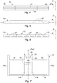
figure 5 est une vue de côté d'un insert métallique de la bande de frottement selon le premier mode de réalisation de l'invention ; - la
figure 6 est une vue de côté d'une variante du premier mode de réalisation dans lequel la bande de frottement comprend un insert métallique en plusieurs tronçons ; - la
figure 7 est une vue en coupe d'un support collecteur d'électricité de la bande de frottement selon le premier mode de réalisation de l'invention ; - la
figure 8 est une vue de côté d'un insert métallique d'une bande de frottement pour pantographe de véhicule ferroviaire selon un deuxième mode de réalisation de l'invention : - la
figure 9 est une vue de dessus et de détail d'un support collecteur d'électricité de la bande de frottement selon le deuxième mode de réalisation de l'invention ; - la
figure 10 est une vue de détail, en coupe suivant le plan D-D défini sur lesfigures 8 et 9 , de la bande de frottement selon le deuxième mode de réalisation de l'invention ; - la
figure 11 une vue de détail, en coupe suivant le plan E-E illustré auxfigures 8 et 9 , de la bande de frottement selon le deuxième mode de réalisation de l'invention ; - la
figure 12 est une vue de détail, en coupe suivant le plan F-F défini sur lesfigures 8 et 9 , de la bande de frottement selon le deuxième mode de réalisation de l'invention ; - la
figure 13 est une vue de côté d'une bande de frottement pour pantographe de véhicule ferroviaire selon un troisième mode de réalisation de l'invention ; - la
figure 14 est une vue en coupe de la bande de frottement selon le troisième mode de réalisation de l'invention, suivant le plan G-G défini sur lafigure 13 ; - la
figure 15 est une vue en coupe de la bande de frottement selon le troisième mode de réalisation de l'invention, suivant le plan H-H défini sur lafigure 13 ; - la
figure 16 est une vue partielle, en coupe, d'une variante de réalisation de la bande de frottement illustrée à lafigure 14 .
- the
figure 1 is a side view of a friction strip for a rail vehicle pantograph according to a first embodiment of the invention; - the
figure 2 is a sectional view of the friction strip according to the first embodiment of the invention, along the plane AA defined on thefigure 1 ; - the
figure 3 is a sectional view of the friction strip according to the first embodiment of the invention, along the plane BB defined on thefigure 1 ; - the
figure 4 is a top view of the friction strip according to the first embodiment of the invention, according to arrow C shown in thefigure 1 ; - the
figure 5 is a side view of a metal insert of the friction strip according to the first embodiment of the invention; - the
figure 6 is a side view of a variant of the first embodiment in which the friction strip comprises a metal insert in several sections; - the
figure 7 is a sectional view of an electrical collector support of the friction strip according to the first embodiment of the invention; - the
figure 8 is a side view of a metal insert of a friction strip for a rail vehicle pantograph according to a second embodiment of the invention: - the
figure 9 is a top view and in detail of an electrical collector support of the friction strip according to the second embodiment of the invention; - the
figure 10 is a detail view, in section along the DD plane defined on theFigures 8 and 9 , of the friction strip according to the second embodiment of the invention; - the
figure 11 a detail view, in section along the EE plan illustrated inFigures 8 and 9 , of the friction strip according to the second embodiment of the invention; - the
figure 12 is a detail view, in section along the FF plane defined on theFigures 8 and 9 , of the friction strip according to the second embodiment of the invention; - the
figure 13 is a side view of a friction strip for a rail vehicle pantograph according to a third embodiment of the invention; - the
figure 14 is a sectional view of the friction strip according to the third embodiment of the invention, along the plane GG defined on thefigure 13 ; - the
figure 15 is a sectional view of the friction strip according to the third embodiment of the invention, along the HH plane defined on thefigure 13 ; - the
figure 16 is a partial view, in section, of an alternative embodiment of the friction strip illustrated in thefigure 14 .
Les
On définit un repère orthogonal comprenant une direction d'extension longitudinale X, une direction transversale Y et une direction verticale Z. On notera que la direction transversale Y correspond à la direction suivant laquelle le véhicule ferroviaire se déplace.An orthogonal coordinate system is defined comprising a direction of longitudinal extension X, a transverse direction Y and a vertical direction Z. It will be noted that the transverse direction Y corresponds to the direction in which the rail vehicle moves.
On définit en outre un plan PX comprenant la direction d'extension longitudinale X. Le plan PX est par exemple défini par la direction d'extension longitudinale X et par la direction verticale Z.A plane P X comprising the direction of longitudinal extension X is further defined. The plane P X is for example defined by the direction of longitudinal extension X and by the vertical direction Z.
La bande de frottement 10, 10A, 10B comprend :
- une première et une deuxième bande 11, 12 de carbone s'étendant parallèlement à la direction d'extension longitudinale X, de part et d'autre du plan PX,
un insert métallique 13 s'étendant suivant la direction d'extension longitudinale X dans le plan PX et ménagé entre la première bande 11 de carbone et la deuxième bande 12 de carbone d'autre part, et- un support collecteur d'électricité 14 auquel sont assemblés les première et deuxième bandes 11, 12 de carbone et l'insert métallique 13 (
figures 2, 3 ,10 à12 et 14 à 15 ).
- a first and a
second strip - a
metal insert 13 extending in the direction of longitudinal extension X in the plane P X and formed between thefirst strip 11 of carbon and thesecond strip 12 of carbon on the other hand, and - an
electricity collector support 14 to which the first and second carbon strips 11, 12 and the metal insert 13 (figures 2, 3 ,10 at12 and 14 to 15 ).
L'insert métallique 13 peut être ménagé au contact de la première bande 11 de carbone d'une part et de la deuxième bande 12 de carbone d'autre part. L'insert métallique 13 peut aussi être ménagé avec jeu entre les première et deuxième bandes 11, 12 de carbone.The
Le support collecteur d'électricité 14 est réalisé à partir d'un matériau électriquement conducteur.The
En particulier, le support collecteur d'électricité 14 peut être métallique. Il peut notamment être réalisé à partir d'aluminium.In particular, the
Le support collecteur d'électricité 14 et/ou l'insert métallique 13 comprennent des moyens d'emboîtement élastique 18, 35, 39 coopérant avec l'insert métallique 13 et/ou le support collecteur d'électricité 14, de sorte à assurer l'assemblage de l'insert métallique 13 au support collecteur d'électricité 14 (
Ainsi, l'insert métallique 13 est assemblé au support collecteur d'électricité 14 par emboitement élastique.Thus, the
Un tel assemblage par emboitement élastique est plus industriel. Il permet en effet de limiter le temps nécessaire pour l'assemblage de l'insert métallique 13 et du support collecteur d'électricité 14. Par ailleurs, il représente un coût de fabrication faible pour l'insert métallique 13 et le support collecteur d'électricité 14. Enfin, il assure un assemblage robuste entre l'insert métallique 13 et le support collecteur d'électricité 14. Il impose un contact entre l'insert métallique 13 et le support collecteur d'électricité 14 qui garantit une bonne maîtrise du passage du courant électrique entre l'insert métallique 13 et le support collecteur d'électricité 14. Cet assemblage autorise en outre des dilatations thermiques différentielles entre l'insert métallique 13 et le support collecteur d'électricité 14.Such an assembly by elastic interlocking is more industrial. It in fact makes it possible to limit the time necessary for assembling the
Les
Le support collecteur d'électricité 14 s'étend parallèlement à la direction d'extension longitudinale X (
Le support collecteur d'électricité 14 est montré plus en détail à la
Le support collecteur d'électricité 14 comprend une paroi inférieure 15 et une paroi supérieure 16 suivant la direction verticale Z. La paroi supérieure 16 est agencée en regard des première et deuxième bandes 11, 12 de carbone et de l'insert métallique 13. Les parois inférieure 15 et supérieure 16 sont par exemple reliées l'une à l'autre par l'intermédiaire d'une pluralité de parois latérales 17a, 17b. Les parois latérales 17a, 17b peuvent être verticales (parallèles au plan Px) ou légèrement inclinées par rapport au plan Px, par exemple jusqu'à 10°.The
Par exemple, le support collecteur d'électricité 14 comprend deux premières parois latérales 17a agencées de part et d'autre du plan PX et reliant entre eux des bords longitudinaux des parois inférieure 15 et supérieure 16. Le support collecteur d'électricité 14 comprend en outre deux deuxièmes parois latérales 17b également agencées de part et d'autre du plan PX et reliant chacune la paroi inférieure 15 et la paroi supérieure 16 entre l'une des premières parois latérales 17a et le plan PX.For example, the
La paroi supérieure 16 du support collecteur d'électricité 14 comprend une paire de languettes 18 déformables élastiquement s'étendant depuis la paroi supérieure 16 en regard l'une de l'autre et définissant ensemble un espace 19 accueillant l'insert métallique 13 (
Plus précisément, lors de l'assemblage de l'insert métallique 13 et du support collecteur d'électricité 14, l'insert métallique 13 est inséré en force entre les languettes 18 dans l'espace 19, les languettes 18 s'écartant l'une par rapport à l'autre par déformation élastique à mesure que l'insert métallique 13 s'enfonce dans l'espace 19. Une fois l'insert métallique 13 installé entre les languettes 18, la déformation élastique desdites languettes 18 tend à exercer un effort de retour élastique en direction de l'insert métallique 13, enserrant ce dernier et assurant ainsi l'assemblage de l'insert métallique 13 au support collecteur d'électricité 14 (
En outre, le contact entre les languettes 18 et l'insert métallique 13 assure le passage du courant électrique entre l'insert métallique 13 et le support collecteur d'électricité 14.In addition, the contact between the
Les languettes 18 s'étendent par exemple depuis la paroi supérieure 16, globalement parallèlement au plan Px. Les languettes 18 sont agencées de part et d'autre du plan Px.The
Chacune des languettes 18 comprend en outre une dent 20 déformable élastiquement et plastiquement s'étendant depuis une extrémité libre 21 de ladite languette 18, dans l'espace 19 défini entre la paire de languettes 18 et accueillant l'insert métallique 13 (
Plus précisément, lors de l'assemblage de l'insert métallique 13 et du support collecteur d'électricité 14, les languettes 18 se déforment élastiquement à mesure que l'insert métallique 13 est introduit dans l'espace 19, s'écartant l'une par rapport à l'autre, tandis que les dents 20 sont partiellement écrasées par l'insert métallique 13. Une fois l'insert métallique 13 installé entre les languettes 18, la déformation élastique desdites languettes 18 et l'écrasement partiel des dents 20 (déformation plastique locale) tendent ensemble à exercer un effort de retour élastique en direction de l'insert métallique 13, enserrant ce dernier et assurant ainsi l'assemblage de l'insert métallique 13 au support collecteur d'électricité 14 (
Le serrage des languettes 18 et plus précisément de leurs dents 20 contre l'insert métallique 13 assure le passage du courant électrique entre l'insert métallique 13 et le support collecteur d'électricité 14. Le passage du courant électrique est en outre amélioré par les dents 20 des languettes 18 qui ont été légèrement émoussées par le passage en force de l'insert métallique 13 et augmentent ainsi la surface de contact entre l'insert métallique 13 et le support collecteur d'électricité 14 (
Par ailleurs, l'insert métallique 13 conserve une liberté de glissement suivant la direction d'extension longitudinale X par rapport au support collecteur d'électricité 14 permettant de compenser l'éventuel écart de dilatation thermique entre l'insert métallique 13 et le support collecteur d'électricité 14. Cela est notamment le cas, lorsque l'insert métallique 13 et le support collecteur d'électricité 14 sont réalisés à partir d'un matériau différent. L'insert métallique 13 est par exemple réalisé à partir de fonte, tandis que le support collecteur d'électricité 14 est par exemple réalisé à partir d'aluminium.Furthermore, the
L'insert métallique 13 présente une forme globalement parallélépipédique, notamment une forme globalement de pavé droit.The
L'insert métallique 13 est montré plus en détail sur la
L'insert métallique 13 comprend une portion inférieure et une portion supérieure suivant la direction verticale Z. La portion inférieure est agencée en regard de la paroi supérieure 16 du support collecteur d'électricité 14.The
La portion inférieure de l'insert métallique 13 comprend par exemple au moins une ouverture 27 de forme allongée s'étendant suivant la direction d'extension longitudinale X (
Les ouvertures 27 sont par exemple réalisées par oxydécoupage, notamment lorsque l'insert métallique 13 est réalisé à partir de tôle. Les ouvertures 27 peuvent alternativement être réalisées lors du moulage de l'insert métallique 13, notamment lorsque l'insert métallique 13 est réalisé à partir de fonte.The
En variante, la ou les ouvertures 27 peuvent être remplacées par une ou des rainures s'étendant, de part et d'autre du plan Px, parallèlement à la direction d'extension longitudinale X (
L'insert métallique 13 peut être réalisé en plusieurs tronçons répartis suivant la direction longitudinale X et assemblés à un même support collecteur d'électricité 14. Dans ce cas, il peut être prévu un léger jeu suivant la direction d'extension longitudinale X entre les tronçons de l'insert métallique 13, afin de réduire les contraintes dues à la dilatation de chacun des tronçons. Cette variante est représentée sur la
Les première et deuxième bandes 11, 12 de carbone présentent une forme globalement parallélépipédique, notamment une forme globalement de pavé droit (
Les première et deuxième bandes 11, 12 de carbone comprennent une portion inférieure et une portion supérieure suivant la direction verticale Z. La portion inférieure est agencée en regard de la paroi supérieure 16 du support collecteur d'électricité 14.The first and second carbon strips 11, 12 comprise a lower portion and an upper portion in the vertical direction Z. The lower portion is arranged opposite the
La portion inférieure comprend une surface inférieure 30 installée contre la paroi supérieure 16 du support collecteur d'électricité 14 (
La portion inférieure et la portion supérieure de chacune des première et deuxième bandes 11, 12 de carbone sont par exemple délimitées par un premier épaulement 31 s'étendant parallèlement à la direction d'extension longitudinale X et formant un logement accueillant la languette 18 correspondante du support collecteur d'électricité 14 (
Les premières parois latérales 17a du support collecteur d'électricité 14 se prolongent par exemple au-delà de la paroi supérieure 16 dudit support collecteur d'électricité 14 (
Le prolongement des premières parois latérales 17a forme une butée qui permet de réduire le cisaillement de la colle, lors de l'assemblage de l'insert métallique 13 sous l'effet de l'effort appliqué par les languettes 18 sur les première et deuxième bandes 11, 12 de carbone. La qualité de l'assemblage et le passage du courant entre l'insert métallique 13 et le support collecteur d'électricité 14 sont ainsi mieux maitrisés.The extension of the
Les première et deuxième bandes 11, 12 de carbone comprennent par exemple chacune un deuxième épaulement 33 s'étendant parallèlement à la direction d'extension longitudinale X et formant un logement accueillant le prolongement de la première paroi latérale 17a correspondant du support collecteur d'électricité 14 (
La bande de frottement 10 est par exemple symétrique par rapport au pan Px.The
Les
Selon ce mode de réalisation de l'invention, la paroi supérieure 16 du support collecteur d'électricité 14 comprend au moins une ouverture 34 globalement de forme allongée s'étendant suivant la direction d'extension longitudinale X, à l'intérieur de laquelle l'insert métallique 13 est logé (
Plus précisément, lors de l'assemblage de l'insert métallique 13 sur le support collecteur d'électricité 14, l'insert métallique 13 est inséré en force dans la ou les ouvertures 34 du support collecteur d'électricité 14, le rebord 35 de ladite ou desdites ouvertures 34 se déformant élastiquement à mesure que l'insert métallique 13 s'enfonce. La progression de l'enfoncement l'insert métallique 13 occasionne son serrage au niveau du rebord 35 de la ou des ouvertures 34 du support collecteur d'électricité 14. Une fois l'insert métallique 13 installé dans la ou les ouvertures 34 du support collecteur d'électricité 14, la déformation élastique du rebord 35 de ladite ou desdites ouvertures 34 tend à exercer un effort de retour élastique en direction de l'insert métallique 13. Ce dernier est enserré par le rebord 35 de la ou des ouvertures 34 (
Ce deuxième mode de réalisation de l'invention est particulièrement avantageux car il permet d'utiliser des profilés de support collecteur d'électricité 14 standard et de réaliser des découpes de sorte à former les ouvertures 34.This second embodiment of the invention is particularly advantageous because it makes it possible to use standard electricity collector support profiles 14 and to make cutouts so as to form the
De préférence, la paroi supérieure 16 du support collecteur d'électricité 14 comprend une pluralité d'ouvertures 34 s'étendant successivement suivant la direction d'extension longitudinale X.Preferably, the
La ou les ouvertures 34 du support collecteur d'électricité 14 sont par exemple réalisées par usinage dans la paroi supérieure 16 du support collecteur d'électricité 14.The opening or
La portion inférieure de l'insert métallique 13 comprend successivement suivant la direction d'extension longitudinale X, au moins un talon 36 coopérant avec le rebord 35 de la ou des ouvertures 34 du support collecteur d'électricité 14 et au moins un logement 37 au niveau duquel la portion inférieure de l'insert métallique 13 épouse la paroi supérieure 16 du support collecteur d'électricité 14 (
Afin de faciliter l'insertion de l'insert métallique 13 dans la ou les ouvertures 34 du support collecteur d'électricité 14, notamment le centrage de l'insert métallique 13 par rapport à la ou aux ouvertures 34 du support collecteur d'électricité 14, la portion inférieure de l'insert métallique 13 est par exemple chanfreinée (
Le rebord 35 de la ou des ouvertures 34 du support collecteur d'électricité 14 pourra comprendre, de chaque côté du plan Px, une paire d'encoches 38 définissant ensemble une languette 39 déformable élastiquement coopérant avec l'insert métallique 13 (
Les languettes 39 du support collecteur d'électricité 14 coopèrent par exemple avec la ou les ouvertures 27 ou la ou les rainures de la portion inférieure de l'insert métallique 13. La ou les ouvertures 27 de l'insert métallique 13 s'engagent avec les languettes 39 du support collecteur d'électricité 14, de sorte à bloquer l'insert métallique 13 en translation suivant la direction verticale Z dans un sens opposée au support collecteur d'électricité 14 (
Les encoches 38 s'étendant par exemple sensiblement perpendiculairement au plan Px.The
Le rebord 35 de la ou des ouvertures 34 du support collecteur d'électricité 14 est par exemple en retrait par rapport aux languettes 39 (
Les encoches 24 sont par exemple réalisées symétriquement par rapport au plan Px.The notches 24 are for example made symmetrically with respect to the plane P x .
La ou les ouvertures 27 ou la ou les rainures de l'insert métallique 13 sont par exemple ménagées sur le ou les talons 36 dudit insert métallique 13.The opening (s) 27 or the groove (s) of the
Les
Dans ce mode de réalisation de l'invention, les rainures 32 formées par le prolongement des premières parois latérales 17a et les languettes 18 présentent une section transversale par rapport à la direction d'extension longitudinale X de forme globalement trapézoïdale (
Les première et deuxième bandes 11, 12 de carbone peuvent ainsi être assemblées au support collecteur d'électricité 14 par glissement desdites bandes 11, 12 de carbone parallèlement à la direction d'extension longitudinale X dans leurs rainures 32 respectives.The first and
Le sertissage des languettes 18 du support collecteur d'électricité 14 contre la portion inférieure des première et deuxième bandes 11, 12 de carbone est réalisé lorsque l'insert métallique 13 est inséré entre les languettes 18 du support collecteur d'électricité 14, entraînant leur écartement l'une par rapport à l'autre par déformation élastique. L'insert métallique 13 permet ainsi via les languettes 18 d'appliquer un effort de serrage sur la première et la deuxième bandes 11, 12 de carbone. Cet effort de serrage permet au courant électrique de passer des première et deuxième bandes (11, 12) de carbone au support collecteur d'électricité 14.The crimping of the
Il est ainsi possible de s'affranchir du collage des première et deuxième bandes 11, 12 au support collecteur d'électricité 14. Cela permet de supprimer les risques de décollage des première et deuxième bandes 11, 12 de carbone, notamment en cas d'échauffement trop important desdites bandes 11, 12 de carbone, échauffement qui serait transmis à la colle.It is thus possible to dispense with the bonding of the first and
Le prolongement des premières parois latérales 17a du support collecteur d'électricité 14 est par exemple incliné par rapport au plan Px, de sorte à former des rainures 32 présentant une section transversale par rapport à la direction d'extension longitudinale X de forme globalement trapézoïdale (
La paroi supérieure 16 du support collecteur d'électricité 14 est par exemple, au niveau de chacune des rainures 32 formées entre les languettes 18 et le prolongement des premières parois latérales 17a, bombée en direction de la paroi inférieure 15 (
Comme illustré à la
L'insert métallique 13 peut aussi présenter une section transversale, par rapport à la direction d'extension longitudinale X, en forme de trapèze, la portion inférieure de l'insert métallique 13 comprenant la petite base et la portion supérieure de l'insert métallique 13 comprenant la grande base dudit trapèze (
Les bandes de frottement 10, 10A, 10B décrites ci-dessus sont particulièrement avantageuses car elles permettent de réaliser un assemblage entre l'insert métallique 13 et le support collecteur d'électricité 14 par emboitement élastique. Ainsi, les bandes de frottement 10, 10A, 10B peuvent être assemblées plus rapidement et à moindre coût.The friction strips 10, 10A, 10B described above are particularly advantageous because they allow an assembly to be made between the
Claims (15)
- Contact strip (10, 10A, 10B) for a rail vehicle pantograph, comprising:- a first and a second carbon strip (11, 12) extending parallel to a longitudinal extension direction (X) and on either side of a longitudinal extension plane (Px) comprising said longitudinal extension direction,- a metal insert (13) extending along the longitudinal extension direction (X) in the longitudinal extension plane (Px) and arranged between the first carbon strip (11) and the second carbon strip (12), and- an electricity collector support (14) to which are assembled the first and second carbon strips (11, 12) and the metal insert (13),the contact strip (10, 10A, 10B) being characterised in that the electricity collector support (14) and/or the metal insert (13) comprise elastic interlocking means (18, 15, 39) engaging with the metal insert (13) and/or the electricity collector support (14), so as to ensure the assembly of the metal insert (13) to the electricity collector support (14) and the passage of the electric current between the metal insert (13) and the electricity collector support (14).
- Contact strip (10, 10B) according to claim 1, wherein the electricity collector support comprises a wall (16), termed upper wall, arranged facing the first and second carbon strips (11, 12) and the metal insert (13), and wherein the elastic interlocking means comprise a pair of elastically deformable flaps (18) extending from the upper wall (16) facing one another and together defining a space (17) receiving the metal insert (13).
- Contact strip (10, 10B) according to claim 2, wherein the flaps (18) each comprise an elastically and plastically deformable tooth (20) extending from a free end (21) of said flap, into the space (17) defined between said flaps and receiving the metal insert (13), said teeth (20) engaging with the metal insert (13).
- Contact strip (10, 10B) according to claim 2 or 3, wherein the electricity collector support (14) comprises two walls (17a), termed side walls, mainly orthogonal with respect to the upper wall (16), said side walls being extended beyond the upper wall (16) of said electricity collector support (14), in the direction of the first and second carbon strips (11, 12), and wherein said extension of each of the side walls (17a) forms, with one of the flaps (18), a groove (32) extending parallel to the longitudinal extension direction (X) and housing one of the first and second carbon strips (11, 12).
- Contact strip (10B) according to claim 4, wherein said grooves (32) have a transversal cross-section with respect to the longitudinal extension direction (X) of mainly trapezoidal shape, the first and second carbon strips (11, 12) comprising a portion, termed lower portion, facing the upper wall (16) having a transverse cross-section with respect to the longitudinal extension direction (X) of complementary shape with that of said grooves (32), the metal insert (13) applying via the flaps (18), a clamping force on the first and the second carbon strips (11, 12).
- Contact strip (10B) according to claim 5, wherein the upper wall (16) of the electricity collector support (14) is curved in a direction opposite the first and second carbon strips (11, 12), at the level of each of the grooves (32).
- Contact strip (10B) according to claim 5 or 6, wherein spoilers (40) and housings (41) are correspondingly provided on the flaps (18) and extensions of the side walls (17a) and on the lower portion of the first and second carbon strips (11, 12).
- Contact strip (10, 10B) according to one of claims 5 to 7, wherein the metal insert (13) has a transverse cross-section with respect to the trapezium-shaped longitudinal extension direction (X).
- Contact strip (10A) according to claim 1, wherein the electricity collector support (14) comprises a wall (16), termed upper wall, arranged facing the first and second carbon strips (11, 12) and the metal insert (13), wherein the upper wall (16) of the electricity collector support (14) comprises at least one opening (34) of elongate shape, extending along the longitudinal extension direction (X), inside which the metal insert (13) is housed, and wherein the elastic interlocking means comprise an elastically deformable edge (35) delimiting the opening(s) (34).
- Contact strip (10A) according to claim 9, wherein the metal insert (13) successively comprises along the longitudinal extension direction (X), at least one stub (36) engaging with the edge (35) of the opening(s) (34) of the electricity collector support (14) and at least one housing (37) at the level of which the metal insert (13) abuts on the upper wall (16) of the electricity collector support (14).
- Contact strip (10A) according to claim 9 or 10, wherein the elastic interlocking means further comprise elastically deformable flaps (39), each defined by a pair of notches (38) extending substantially perpendicularly to the plane (Px) and arranged on the edge (35) of the opening(s) (34).
- Contact strip (10A) according to claim 11, wherein the edge (35) of the opening(s) (34) of the electricity collector support (14) is recessed with respect to the flaps (39).
- Contact strip (10, 10A, 10B) according to any one of claims 1 to 12, wherein the metal insert (13) comprises a portion termed lower portion, comprising at least one groove or one opening (27) of elongate shape, extending along the longitudinal extension direction (X) and engaging with the elastic interlocking means (18, 39) of the electricity collector support (14).
- Pantograph collector head comprising at least one contact strip (10B) according to one of claims 1 to 13.
- Pantograph for rail vehicle comprising a collector head according to claim 14.
Priority Applications (1)
| Application Number | Priority Date | Filing Date | Title |
|---|---|---|---|
| PL17204665T PL3333007T3 (en) | 2016-12-09 | 2017-11-30 | Pantograph wearing strip for railway vehicle |
Applications Claiming Priority (1)
| Application Number | Priority Date | Filing Date | Title |
|---|---|---|---|
| FR1662227A FR3059950B1 (en) | 2016-12-09 | 2016-12-09 | FRICTION TAPE FOR A RAIL VEHICLE PANTOGRAPH |
Publications (2)
| Publication Number | Publication Date |
|---|---|
| EP3333007A1 EP3333007A1 (en) | 2018-06-13 |
| EP3333007B1 true EP3333007B1 (en) | 2020-04-08 |
Family
ID=58010039
Family Applications (1)
| Application Number | Title | Priority Date | Filing Date |
|---|---|---|---|
| EP17204665.8A Active EP3333007B1 (en) | 2016-12-09 | 2017-11-30 | Pantograph wearing strip for railway vehicle |
Country Status (6)
| Country | Link |
|---|---|
| EP (1) | EP3333007B1 (en) |
| ES (1) | ES2799703T3 (en) |
| FR (1) | FR3059950B1 (en) |
| PL (1) | PL3333007T3 (en) |
| RU (1) | RU2748523C2 (en) |
| ZA (1) | ZA201707921B (en) |
Cited By (1)
| Publication number | Priority date | Publication date | Assignee | Title |
|---|---|---|---|---|
| EP4265465A1 (en) * | 2022-03-31 | 2023-10-25 | Conductix-Wampfler GmbH | Sliding contact holder, sliding contact, current collector and sliding contact system |
Family Cites Families (5)
| Publication number | Priority date | Publication date | Assignee | Title |
|---|---|---|---|---|
| FR1110518A (en) * | 1954-09-10 | 1956-02-14 | Improvements to power outlet devices | |
| US3405240A (en) * | 1967-01-04 | 1968-10-08 | Insul 8 Corp | Mobile electrification collector head |
| FR2412183A1 (en) * | 1977-12-13 | 1979-07-13 | Tourtellier Sa Ets | BROOM FOR MANIFOLD |
| SU1481103A1 (en) * | 1987-05-04 | 1989-05-23 | Всесоюзный Научно-Исследовательский Институт Железнодорожного Транспорта | Device for attaching vehicle current collector insert |
| DE102010003874A1 (en) * | 2010-04-12 | 2011-10-13 | Hoffmann & Co. Elektrokohle Ag | Sanding strip for a sliding contact device and method for producing a sanding strip |
-
2016
- 2016-12-09 FR FR1662227A patent/FR3059950B1/en active Active
-
2017
- 2017-11-22 ZA ZA2017/07921A patent/ZA201707921B/en unknown
- 2017-11-30 EP EP17204665.8A patent/EP3333007B1/en active Active
- 2017-11-30 ES ES17204665T patent/ES2799703T3/en active Active
- 2017-11-30 PL PL17204665T patent/PL3333007T3/en unknown
- 2017-12-08 RU RU2017142971A patent/RU2748523C2/en active
Non-Patent Citations (1)
| Title |
|---|
| None * |
Cited By (1)
| Publication number | Priority date | Publication date | Assignee | Title |
|---|---|---|---|---|
| EP4265465A1 (en) * | 2022-03-31 | 2023-10-25 | Conductix-Wampfler GmbH | Sliding contact holder, sliding contact, current collector and sliding contact system |
Also Published As
| Publication number | Publication date |
|---|---|
| FR3059950B1 (en) | 2019-05-17 |
| RU2017142971A (en) | 2019-06-10 |
| ES2799703T3 (en) | 2020-12-21 |
| RU2748523C2 (en) | 2021-05-26 |
| EP3333007A1 (en) | 2018-06-13 |
| RU2017142971A3 (en) | 2021-03-16 |
| FR3059950A1 (en) | 2018-06-15 |
| PL3333007T3 (en) | 2020-09-07 |
| ZA201707921B (en) | 2018-11-28 |
Similar Documents
| Publication | Publication Date | Title |
|---|---|---|
| EP0679565B1 (en) | Front end of an automobile | |
| FR2622956A1 (en) | PROFILE IN TWO SECTIONS, ESPECIALLY BODY CHUTE AND COVER | |
| CA2660635C (en) | Method for manufacturing a panel assembly | |
| FR2730521A1 (en) | WINDOW REGULATOR | |
| FR2759636A1 (en) | ELECTRIC HEATING DEVICE, PARTICULARLY FOR A MOTOR VEHICLE | |
| EP3333007B1 (en) | Pantograph wearing strip for railway vehicle | |
| FR2988412A1 (en) | IMPROVED MODULAR ASSEMBLY FOR REALIZING A FLOOR COVER | |
| FR2947331A1 (en) | Heat exchanger, has bundle of tubes arranged between collector boxes for circulation of fluid, where sealing joint of one collector box includes obturation part partially closing end of inactive tube opening in collector box | |
| FR2984475A1 (en) | HEAT EXCHANGER COLLECTOR BOX, IN PARTICULAR FOR MOTOR VEHICLE, COVER OF SAID BOX AND HEAT EXCHANGER COMPRISING SUCH A BOX | |
| FR2693040A1 (en) | Connector for electric cables. | |
| EP0028951A2 (en) | Heat exchanger comprising a bundle of tubes opening into collector panels mechanically associated with water vessels | |
| FR3129645A1 (en) | Wiper blade comprising a heating element | |
| EP1753096B1 (en) | Rail arrangement for an electrical power source device with mobile electrical connector | |
| FR2775766A1 (en) | HEAT EXCHANGER WITH PROTECTED FINS, ESPECIALLY FOR MOTOR VEHICLES | |
| WO2010133491A1 (en) | Header box for a heat exchanger, in particular a multiple flow heat exchanger | |
| FR3017831A1 (en) | VEHICLE SEAT ADJUSTMENT SLIDER, DEFLECTOR FOR SUCH A SLIDER AND VEHICLE THUS EQUIPPED | |
| EP3356686B1 (en) | Assembly of sheet metal elements comprising a shiplap | |
| FR2967764A1 (en) | COLLECTOR BOX AND CORRESPONDING HEAT EXCHANGER | |
| EP3138140A1 (en) | Spring support for a tube, in particular a tube of a heat exchanger intended to come into contact with a motor vehicle battery | |
| EP3997759B1 (en) | Connection device for grounding an electrical apparatus and/or creating an equipotential link between conductive elements | |
| FR2770934A1 (en) | CONNECTOR WITH JAWS LIKELY TO INTERLOCK | |
| FR2634070A1 (en) | INSULATED CONNECTOR FOR ELECTRIC CABLES | |
| FR2974676A1 (en) | CONNECTING SLEEVE FOR ELECTRIC CABLES | |
| FR2679186A1 (en) | Windscreen wiper equipped with an aerodynamic deflector | |
| FR2841203A1 (en) | GLASS PAVILION FOR MOTOR VEHICLE |
Legal Events
| Date | Code | Title | Description |
|---|---|---|---|
| PUAI | Public reference made under article 153(3) epc to a published international application that has entered the european phase |
Free format text: ORIGINAL CODE: 0009012 |
|
| STAA | Information on the status of an ep patent application or granted ep patent |
Free format text: STATUS: THE APPLICATION HAS BEEN PUBLISHED |
|
| AK | Designated contracting states |
Kind code of ref document: A1 Designated state(s): AL AT BE BG CH CY CZ DE DK EE ES FI FR GB GR HR HU IE IS IT LI LT LU LV MC MK MT NL NO PL PT RO RS SE SI SK SM TR |
|
| AX | Request for extension of the european patent |
Extension state: BA ME |
|
| STAA | Information on the status of an ep patent application or granted ep patent |
Free format text: STATUS: REQUEST FOR EXAMINATION WAS MADE |
|
| 17P | Request for examination filed |
Effective date: 20181113 |
|
| RBV | Designated contracting states (corrected) |
Designated state(s): AL AT BE BG CH CY CZ DE DK EE ES FI FR GB GR HR HU IE IS IT LI LT LU LV MC MK MT NL NO PL PT RO RS SE SI SK SM TR |
|
| GRAP | Despatch of communication of intention to grant a patent |
Free format text: ORIGINAL CODE: EPIDOSNIGR1 |
|
| STAA | Information on the status of an ep patent application or granted ep patent |
Free format text: STATUS: GRANT OF PATENT IS INTENDED |
|
| INTG | Intention to grant announced |
Effective date: 20191031 |
|
| GRAS | Grant fee paid |
Free format text: ORIGINAL CODE: EPIDOSNIGR3 |
|
| GRAA | (expected) grant |
Free format text: ORIGINAL CODE: 0009210 |
|
| STAA | Information on the status of an ep patent application or granted ep patent |
Free format text: STATUS: THE PATENT HAS BEEN GRANTED |
|
| AK | Designated contracting states |
Kind code of ref document: B1 Designated state(s): AL AT BE BG CH CY CZ DE DK EE ES FI FR GB GR HR HU IE IS IT LI LT LU LV MC MK MT NL NO PL PT RO RS SE SI SK SM TR |
|
| REG | Reference to a national code |
Ref country code: CH Ref legal event code: EP Ref country code: AT Ref legal event code: REF Ref document number: 1253920 Country of ref document: AT Kind code of ref document: T Effective date: 20200415 |
|
| REG | Reference to a national code |
Ref country code: DE Ref legal event code: R096 Ref document number: 602017014315 Country of ref document: DE |
|
| REG | Reference to a national code |
Ref country code: IE Ref legal event code: FG4D Free format text: LANGUAGE OF EP DOCUMENT: FRENCH |
|
| REG | Reference to a national code |
Ref country code: NL Ref legal event code: FP |
|
| REG | Reference to a national code |
Ref country code: LT Ref legal event code: MG4D |
|
| PG25 | Lapsed in a contracting state [announced via postgrant information from national office to epo] |
Ref country code: LT Free format text: LAPSE BECAUSE OF FAILURE TO SUBMIT A TRANSLATION OF THE DESCRIPTION OR TO PAY THE FEE WITHIN THE PRESCRIBED TIME-LIMIT Effective date: 20200408 Ref country code: NO Free format text: LAPSE BECAUSE OF FAILURE TO SUBMIT A TRANSLATION OF THE DESCRIPTION OR TO PAY THE FEE WITHIN THE PRESCRIBED TIME-LIMIT Effective date: 20200708 Ref country code: SE Free format text: LAPSE BECAUSE OF FAILURE TO SUBMIT A TRANSLATION OF THE DESCRIPTION OR TO PAY THE FEE WITHIN THE PRESCRIBED TIME-LIMIT Effective date: 20200408 Ref country code: FI Free format text: LAPSE BECAUSE OF FAILURE TO SUBMIT A TRANSLATION OF THE DESCRIPTION OR TO PAY THE FEE WITHIN THE PRESCRIBED TIME-LIMIT Effective date: 20200408 Ref country code: IS Free format text: LAPSE BECAUSE OF FAILURE TO SUBMIT A TRANSLATION OF THE DESCRIPTION OR TO PAY THE FEE WITHIN THE PRESCRIBED TIME-LIMIT Effective date: 20200808 Ref country code: GR Free format text: LAPSE BECAUSE OF FAILURE TO SUBMIT A TRANSLATION OF THE DESCRIPTION OR TO PAY THE FEE WITHIN THE PRESCRIBED TIME-LIMIT Effective date: 20200709 Ref country code: PT Free format text: LAPSE BECAUSE OF FAILURE TO SUBMIT A TRANSLATION OF THE DESCRIPTION OR TO PAY THE FEE WITHIN THE PRESCRIBED TIME-LIMIT Effective date: 20200817 |
|
| REG | Reference to a national code |
Ref country code: AT Ref legal event code: MK05 Ref document number: 1253920 Country of ref document: AT Kind code of ref document: T Effective date: 20200408 |
|
| PG25 | Lapsed in a contracting state [announced via postgrant information from national office to epo] |
Ref country code: RS Free format text: LAPSE BECAUSE OF FAILURE TO SUBMIT A TRANSLATION OF THE DESCRIPTION OR TO PAY THE FEE WITHIN THE PRESCRIBED TIME-LIMIT Effective date: 20200408 Ref country code: HR Free format text: LAPSE BECAUSE OF FAILURE TO SUBMIT A TRANSLATION OF THE DESCRIPTION OR TO PAY THE FEE WITHIN THE PRESCRIBED TIME-LIMIT Effective date: 20200408 Ref country code: LV Free format text: LAPSE BECAUSE OF FAILURE TO SUBMIT A TRANSLATION OF THE DESCRIPTION OR TO PAY THE FEE WITHIN THE PRESCRIBED TIME-LIMIT Effective date: 20200408 Ref country code: BG Free format text: LAPSE BECAUSE OF FAILURE TO SUBMIT A TRANSLATION OF THE DESCRIPTION OR TO PAY THE FEE WITHIN THE PRESCRIBED TIME-LIMIT Effective date: 20200708 |
|
| REG | Reference to a national code |
Ref country code: ES Ref legal event code: FG2A Ref document number: 2799703 Country of ref document: ES Kind code of ref document: T3 Effective date: 20201221 |
|
| PG25 | Lapsed in a contracting state [announced via postgrant information from national office to epo] |
Ref country code: AL Free format text: LAPSE BECAUSE OF FAILURE TO SUBMIT A TRANSLATION OF THE DESCRIPTION OR TO PAY THE FEE WITHIN THE PRESCRIBED TIME-LIMIT Effective date: 20200408 |
|
| REG | Reference to a national code |
Ref country code: DE Ref legal event code: R097 Ref document number: 602017014315 Country of ref document: DE |
|
| PG25 | Lapsed in a contracting state [announced via postgrant information from national office to epo] |
Ref country code: RO Free format text: LAPSE BECAUSE OF FAILURE TO SUBMIT A TRANSLATION OF THE DESCRIPTION OR TO PAY THE FEE WITHIN THE PRESCRIBED TIME-LIMIT Effective date: 20200408 Ref country code: DK Free format text: LAPSE BECAUSE OF FAILURE TO SUBMIT A TRANSLATION OF THE DESCRIPTION OR TO PAY THE FEE WITHIN THE PRESCRIBED TIME-LIMIT Effective date: 20200408 Ref country code: AT Free format text: LAPSE BECAUSE OF FAILURE TO SUBMIT A TRANSLATION OF THE DESCRIPTION OR TO PAY THE FEE WITHIN THE PRESCRIBED TIME-LIMIT Effective date: 20200408 Ref country code: EE Free format text: LAPSE BECAUSE OF FAILURE TO SUBMIT A TRANSLATION OF THE DESCRIPTION OR TO PAY THE FEE WITHIN THE PRESCRIBED TIME-LIMIT Effective date: 20200408 Ref country code: SM Free format text: LAPSE BECAUSE OF FAILURE TO SUBMIT A TRANSLATION OF THE DESCRIPTION OR TO PAY THE FEE WITHIN THE PRESCRIBED TIME-LIMIT Effective date: 20200408 |
|
| PLBE | No opposition filed within time limit |
Free format text: ORIGINAL CODE: 0009261 |
|
| STAA | Information on the status of an ep patent application or granted ep patent |
Free format text: STATUS: NO OPPOSITION FILED WITHIN TIME LIMIT |
|
| PG25 | Lapsed in a contracting state [announced via postgrant information from national office to epo] |
Ref country code: SK Free format text: LAPSE BECAUSE OF FAILURE TO SUBMIT A TRANSLATION OF THE DESCRIPTION OR TO PAY THE FEE WITHIN THE PRESCRIBED TIME-LIMIT Effective date: 20200408 |
|
| 26N | No opposition filed |
Effective date: 20210112 |
|
| PG25 | Lapsed in a contracting state [announced via postgrant information from national office to epo] |
Ref country code: SI Free format text: LAPSE BECAUSE OF FAILURE TO SUBMIT A TRANSLATION OF THE DESCRIPTION OR TO PAY THE FEE WITHIN THE PRESCRIBED TIME-LIMIT Effective date: 20200408 |
|
| PG25 | Lapsed in a contracting state [announced via postgrant information from national office to epo] |
Ref country code: MC Free format text: LAPSE BECAUSE OF FAILURE TO SUBMIT A TRANSLATION OF THE DESCRIPTION OR TO PAY THE FEE WITHIN THE PRESCRIBED TIME-LIMIT Effective date: 20200408 |
|
| REG | Reference to a national code |
Ref country code: CH Ref legal event code: PL |
|
| PG25 | Lapsed in a contracting state [announced via postgrant information from national office to epo] |
Ref country code: LU Free format text: LAPSE BECAUSE OF NON-PAYMENT OF DUE FEES Effective date: 20201130 |
|
| PG25 | Lapsed in a contracting state [announced via postgrant information from national office to epo] |
Ref country code: CH Free format text: LAPSE BECAUSE OF NON-PAYMENT OF DUE FEES Effective date: 20201130 Ref country code: LI Free format text: LAPSE BECAUSE OF NON-PAYMENT OF DUE FEES Effective date: 20201130 |
|
| REG | Reference to a national code |
Ref country code: IE Ref legal event code: MM4A |
|
| PG25 | Lapsed in a contracting state [announced via postgrant information from national office to epo] |
Ref country code: IE Free format text: LAPSE BECAUSE OF NON-PAYMENT OF DUE FEES Effective date: 20201130 |
|
| REG | Reference to a national code |
Ref country code: BE Ref legal event code: PD Owner name: SNCF VOYAGEURS; FR Free format text: DETAILS ASSIGNMENT: CHANGE OF OWNER(S), ASSIGNMENT; FORMER OWNER NAME: GEVERS & ORES Effective date: 20210916 Ref country code: BE Ref legal event code: HC Owner name: SOCIETE NATIONALE SNCF; FR Free format text: DETAILS ASSIGNMENT: CHANGE OF OWNER(S), CHANGE OF OWNER(S) NAME; FORMER OWNER NAME: SNCF MOBILITES Effective date: 20210916 |
|
| PG25 | Lapsed in a contracting state [announced via postgrant information from national office to epo] |
Ref country code: TR Free format text: LAPSE BECAUSE OF FAILURE TO SUBMIT A TRANSLATION OF THE DESCRIPTION OR TO PAY THE FEE WITHIN THE PRESCRIBED TIME-LIMIT Effective date: 20200408 Ref country code: MT Free format text: LAPSE BECAUSE OF FAILURE TO SUBMIT A TRANSLATION OF THE DESCRIPTION OR TO PAY THE FEE WITHIN THE PRESCRIBED TIME-LIMIT Effective date: 20200408 Ref country code: CY Free format text: LAPSE BECAUSE OF FAILURE TO SUBMIT A TRANSLATION OF THE DESCRIPTION OR TO PAY THE FEE WITHIN THE PRESCRIBED TIME-LIMIT Effective date: 20200408 |
|
| PG25 | Lapsed in a contracting state [announced via postgrant information from national office to epo] |
Ref country code: MK Free format text: LAPSE BECAUSE OF FAILURE TO SUBMIT A TRANSLATION OF THE DESCRIPTION OR TO PAY THE FEE WITHIN THE PRESCRIBED TIME-LIMIT Effective date: 20200408 |
|
| GBPC | Gb: european patent ceased through non-payment of renewal fee |
Effective date: 20211130 |
|
| PG25 | Lapsed in a contracting state [announced via postgrant information from national office to epo] |
Ref country code: GB Free format text: LAPSE BECAUSE OF NON-PAYMENT OF DUE FEES Effective date: 20211130 |
|
| REG | Reference to a national code |
Ref country code: DE Ref legal event code: R081 Ref document number: 602017014315 Country of ref document: DE Owner name: SNCF VOYAGEURS, FR Free format text: FORMER OWNER: SNCF MOBILITES, SAINT-DENIS, FR |
|
| PGFP | Annual fee paid to national office [announced via postgrant information from national office to epo] |
Ref country code: NL Payment date: 20231023 Year of fee payment: 7 |
|
| PGFP | Annual fee paid to national office [announced via postgrant information from national office to epo] |
Ref country code: ES Payment date: 20231218 Year of fee payment: 7 |
|
| PGFP | Annual fee paid to national office [announced via postgrant information from national office to epo] |
Ref country code: IT Payment date: 20231110 Year of fee payment: 7 Ref country code: FR Payment date: 20231124 Year of fee payment: 7 Ref country code: DE Payment date: 20231107 Year of fee payment: 7 Ref country code: CZ Payment date: 20231020 Year of fee payment: 7 |
|
| PGFP | Annual fee paid to national office [announced via postgrant information from national office to epo] |
Ref country code: PL Payment date: 20231030 Year of fee payment: 7 Ref country code: BE Payment date: 20231113 Year of fee payment: 7 |
|
| REG | Reference to a national code |
Ref country code: ES Ref legal event code: PC2A Owner name: SNCF VOYAGEURS Effective date: 20240528 |