EP3333007B1 - Schleifleiste für einen stromabnehmer eines schienenfahrzeugs - Google Patents
Schleifleiste für einen stromabnehmer eines schienenfahrzeugs Download PDFInfo
- Publication number
- EP3333007B1 EP3333007B1 EP17204665.8A EP17204665A EP3333007B1 EP 3333007 B1 EP3333007 B1 EP 3333007B1 EP 17204665 A EP17204665 A EP 17204665A EP 3333007 B1 EP3333007 B1 EP 3333007B1
- Authority
- EP
- European Patent Office
- Prior art keywords
- metal insert
- collector support
- longitudinal extension
- electricity
- support
- Prior art date
- Legal status (The legal status is an assumption and is not a legal conclusion. Google has not performed a legal analysis and makes no representation as to the accuracy of the status listed.)
- Active
Links
- 229910052751 metal Inorganic materials 0.000 claims description 156
- 239000002184 metal Substances 0.000 claims description 156
- 230000005611 electricity Effects 0.000 claims description 127
- OKTJSMMVPCPJKN-UHFFFAOYSA-N Carbon Chemical compound [C] OKTJSMMVPCPJKN-UHFFFAOYSA-N 0.000 claims description 66
- 229910052799 carbon Inorganic materials 0.000 claims description 66
- 230000000295 complement effect Effects 0.000 claims description 3
- 210000002105 tongue Anatomy 0.000 description 58
- 230000005489 elastic deformation Effects 0.000 description 6
- 238000010438 heat treatment Methods 0.000 description 4
- 229910001018 Cast iron Inorganic materials 0.000 description 2
- 229910052782 aluminium Inorganic materials 0.000 description 2
- XAGFODPZIPBFFR-UHFFFAOYSA-N aluminium Chemical compound [Al] XAGFODPZIPBFFR-UHFFFAOYSA-N 0.000 description 2
- OKTJSMMVPCPJKN-BJUDXGSMSA-N carbon-11 Chemical compound [11C] OKTJSMMVPCPJKN-BJUDXGSMSA-N 0.000 description 2
- 230000000694 effects Effects 0.000 description 2
- 239000003292 glue Substances 0.000 description 2
- 238000003780 insertion Methods 0.000 description 2
- 230000037431 insertion Effects 0.000 description 2
- 238000004519 manufacturing process Methods 0.000 description 2
- 230000036961 partial effect Effects 0.000 description 2
- 238000013519 translation Methods 0.000 description 2
- 241000826860 Trapezium Species 0.000 description 1
- 239000000853 adhesive Substances 0.000 description 1
- 230000001070 adhesive effect Effects 0.000 description 1
- 239000012298 atmosphere Substances 0.000 description 1
- 230000008901 benefit Effects 0.000 description 1
- 238000005266 casting Methods 0.000 description 1
- 239000004020 conductor Substances 0.000 description 1
- 238000002788 crimping Methods 0.000 description 1
- 230000006866 deterioration Effects 0.000 description 1
- 230000001976 improved effect Effects 0.000 description 1
- 230000000670 limiting effect Effects 0.000 description 1
- 230000009021 linear effect Effects 0.000 description 1
- 238000003754 machining Methods 0.000 description 1
- 230000014759 maintenance of location Effects 0.000 description 1
- 239000000463 material Substances 0.000 description 1
- 238000000034 method Methods 0.000 description 1
- 238000000465 moulding Methods 0.000 description 1
- 229920003023 plastic Polymers 0.000 description 1
- 239000004033 plastic Substances 0.000 description 1
- 230000008569 process Effects 0.000 description 1
- 230000001737 promoting effect Effects 0.000 description 1
- 238000000926 separation method Methods 0.000 description 1
- 238000010008 shearing Methods 0.000 description 1
- 238000003892 spreading Methods 0.000 description 1
- 230000007480 spreading Effects 0.000 description 1
Images


Classifications
-
- B—PERFORMING OPERATIONS; TRANSPORTING
- B60—VEHICLES IN GENERAL
- B60L—PROPULSION OF ELECTRICALLY-PROPELLED VEHICLES; SUPPLYING ELECTRIC POWER FOR AUXILIARY EQUIPMENT OF ELECTRICALLY-PROPELLED VEHICLES; ELECTRODYNAMIC BRAKE SYSTEMS FOR VEHICLES IN GENERAL; MAGNETIC SUSPENSION OR LEVITATION FOR VEHICLES; MONITORING OPERATING VARIABLES OF ELECTRICALLY-PROPELLED VEHICLES; ELECTRIC SAFETY DEVICES FOR ELECTRICALLY-PROPELLED VEHICLES
- B60L5/00—Current collectors for power supply lines of electrically-propelled vehicles
- B60L5/18—Current collectors for power supply lines of electrically-propelled vehicles using bow-type collectors in contact with trolley wire
- B60L5/20—Details of contact bow
- B60L5/205—Details of contact bow with carbon contact members
Definitions
- the invention relates to a friction strip for a pantograph of a railway vehicle, such as a train or a tram.
- a catenary conventionally comprises a horizontal carrying cable on which is suspended a horizontal contact wire in which the electric power current flows and through which the pantograph captures the electric power current.
- the pantograph comprises a bow comprising one or more friction bands extending parallel to a direction of longitudinal, horizontal extension and generally orthogonal to the direction in which the rail vehicle moves and an electricity collector support to which is assembled the friction strip.
- the friction strip is provided for rubbing the catenary, in particular the contact wire, so as to capture the current of electrical supply.
- the large dimension of the friction strip in the direction of longitudinal extension makes it possible to absorb the zigzag of the catenary and the movements of the railway vehicle like the catenary in said direction of longitudinal extension.
- the small dimension of the friction strip in a transverse direction, horizontal and orthogonal to the direction of longitudinal extension allows a linear contact to be made between the friction strip and the contact wire, thus ensuring the passage of the current d power supply of the contact wire from the catenary to the friction strip and therefore to the railway vehicle.
- the electric current flowing through the friction strip may amount to more than 1000 A, thereby causing problems with the heating of the friction strip.
- the metallic insert which is more conductive than the friction strip, for example made of carbon, deflects part of the electric current, so as to reduce the amount of electric current flowing through the friction strip and thus limit their heating.
- the document FR 1 110 518 A describes an example of a friction strip in which the electricity collector support and the metal insert are assembled by screwing.
- This solution requires the use of small screws which are fragile.
- this solution lacks reliability in the sense that it is necessary to tighten the screws so that the current flows, which reduces the freedom of sliding which is necessary to compensate for the differential thermal expansions between the electricity collector support and the metal insert. .
- the document DE 10 2010 042 027 A1 describes another example of a friction strip with a metal insert.
- the metal insert generally comprises a U shape, the branches of which alternately have discontinuities.
- the metal insert is also fixed to the electricity collector support at the core of said U by means of a plurality of screws. This solution is complicated and costly to implement.
- the object of the present invention is to overcome the drawbacks mentioned above, in particular by proposing a friction strip for a pantograph of a railway vehicle having a shorter assembly time, a cost of lower manufacturing and a more robust assembly quality while ensuring good control of the passage of electric current between the carbon strips, the metal insert and the electricity collector support.
- the present invention also relates to a metal insert for a friction strip as previously described.
- the present invention also relates to an electricity collector support for a friction strip as previously described.
- the present invention also relates to a pantograph bow comprising at least one friction strip as previously described.
- the present invention further relates to a pantograph for a railway vehicle comprising a bow comprising at least one friction strip as previously described.
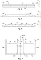
- the Figures 1 to 7 show a friction strip 10 for a pantograph bow (not shown) of a rail vehicle (not shown), in particular of a train or a tram, according to a first embodiment of the invention .
- the Figures 8 to 12 show a friction strip 10A for a rail vehicle pantograph according to a second embodiment of the invention.
- the figures 13 to 16 show a friction strip 10B for a rail vehicle pantograph according to a third embodiment of the invention.
- the common elements between these different embodiments have the same references.
- An orthogonal coordinate system comprising a direction of longitudinal extension X, a transverse direction Y and a vertical direction Z. It will be noted that the transverse direction Y corresponds to the direction in which the rail vehicle moves.
- a plane P X comprising the direction of longitudinal extension X is further defined.
- the plane P X is for example defined by the direction of longitudinal extension X and by the vertical direction Z.
- the metal insert 13 can be arranged in contact with the first carbon strip 11 on the one hand and the second carbon strip 12 on the other hand.
- the metal insert 13 can also be formed with clearance between the first and second strips 11, 12 of carbon.
- the electricity collector support 14 is made from an electrically conductive material.
- the electricity collecting support 14 may be metallic. It can in particular be made from aluminum.
- the electricity collecting support 14 and / or the metal insert 13 comprise elastic interlocking means 18, 35, 39 cooperating with the metal insert 13 and / or the electricity collecting support 14, so as to ensure the assembly of the metal insert 13 to the electricity collector support 14 ( figures 2 , 9, 10 and 11 ) and the passage of electric current between the metal insert 13 and the electricity collecting support 14 via said elastic interlocking means 18, 35, 39.
- the metal insert 13 is assembled to the electricity collecting support 14 by elastic interlocking.
- Such an assembly by elastic interlocking is more industrial. It in fact makes it possible to limit the time necessary for assembling the metal insert 13 and the electricity collector support 14. Furthermore, it represents a low manufacturing cost for the metal insert 13 and the collector support. electricity 14. Finally, it ensures a robust assembly between the metal insert 13 and the electricity collector support 14. It imposes a contact between the metal insert 13 and the electricity collector support 14 which guarantees good control of the passage electrical current between the metal insert 13 and the electricity collecting support 14. This assembly also allows differential thermal expansion between the metal insert 13 and the electricity collecting support 14.
- the Figures 1 to 7 show the friction strip 10 according to the first embodiment of the invention.
- the electricity collector support 14 extends parallel to the direction of longitudinal extension X ( figure 1 ).
- the electricity collector support 14 is shown in more detail in the figure 7 .
- the electricity collector support 14 comprises a lower wall 15 and an upper wall 16 in the vertical direction Z.
- the upper wall 16 is arranged opposite the first and second strips 11, 12 of carbon and the metal insert 13.
- the lower 15 and upper 16 walls are for example connected to each other via a plurality of side walls 17a, 17b.
- the side walls 17a, 17b can be vertical (parallel to the plane P x ) or slightly inclined relative to the plane P x , for example up to 10 °.
- the electricity collector support 14 comprises two first side walls 17a arranged on either side of the plane P X and connecting between them longitudinal edges of the lower 15 and upper walls 16.
- the electricity collector support 14 comprises further two second side walls 17b also arranged on either side of the plane P X and each connecting the bottom wall 15 and the top wall 16 between one of the first side walls 17a and the plane P X.
- the upper wall 16 of the electricity collector support 14 comprises a pair of elastically deformable tongues 18 extending from the upper wall 16 facing each other and together defining a space 19 accommodating the metal insert 13 ( figure 7 ).
- the tongues 18 ensure the assembly of the metal insert 13 to the electricity collector support 14 by elastic fitting ( figures 2 and 3 ).
- the metal insert 13 is forcibly inserted between the tongues 18 in the space 19, the tongues 18 moving apart. one relative to the other by elastic deformation as the metal insert 13 sinks into the space 19.
- the elastic deformation of said tongues 18 tends to exert a elastic return force towards the metal insert 13, enclosing the latter and thus ensuring the assembly of the metal insert 13 to the electricity collector support 14 ( figure 3 ).
- the metal insert 13 is for example inserted by force by means of a press.
- the contact between the tongues 18 and the metal insert 13 ensures the passage of electric current between the metal insert 13 and the electricity collecting support 14.
- the tongues 18 extend for example from the upper wall 16, generally parallel to the plane P x .
- the tongues 18 are arranged on either side of the plane P x .
- Each of the tongues 18 further comprises an elastically and plastically deformable tooth 20 extending from a free end 21 of said tongue 18, in the space 19 defined between the pair of tongues 18 and accommodating the metal insert 13 ( figures 2, 3 and 7 ).
- the teeth 20 of the tongues 18 extend from the free end 21 of said tongues 18 in the direction of one another.
- the teeth 20 cooperate with the metal insert 13.
- the tongues 18 and the teeth 20 together ensure the assembly of the metal insert 13 to the electricity collector support 14 by elastic interlocking.
- the teeth 20 partially retain their elastic property in contact with the metal insert 13.
- the tongues 18 deform elastically as the metal insert 13 is introduced into the space 19, spreading the one with respect to the other, while the teeth 20 are partially crushed by the metal insert 13.
- the elastic deformation of said tongues 18 and the partial crushing of the teeth 20 together tend to exert an elastic return force in the direction of the metal insert 13, enclosing the latter and thus ensuring the assembly of the metal insert 13 to the electricity collector support 14 ( figure 3 ).
- the tightening of the tongues 18 and more precisely of their teeth 20 against the metal insert 13 ensures the passage of the electric current between the metal insert 13 and the electricity collecting support 14.
- the passage of the electric current is further improved by the teeth 20 of the tongues 18 which have been slightly blunted by the forceful passage of the metal insert 13 and thus increase the contact surface between the metal insert 13 and the electricity collector support 14 ( figure 3 ).
- the metal insert 13 retains a freedom of sliding in the direction of longitudinal extension X relative to the electricity collector support 14 making it possible to compensate for any difference in thermal expansion between the metal insert 13 and the collector support electricity 14. This is particularly the case, when the metal insert 13 and the electricity collector support 14 are made from a different material.
- the metal insert 13 is for example made from of cast iron, while the electricity collector support 14 is for example made from aluminum.
- the metal insert 13 has a generally parallelepiped shape, in particular a generally straight block shape.
- the metal insert 13 is shown in more detail on the figure 5 .
- the metal insert 13 comprises a lower portion and an upper portion in the vertical direction Z.
- the lower portion is arranged opposite the upper wall 16 of the electricity collecting support 14.
- the lower portion of the metal insert 13 comprises for example at least one opening 27 of elongated shape extending in the direction of longitudinal extension X ( figure 5 ).
- the opening or openings 27 engage with the teeth 20 of the tongues 18 of the electricity collecting support 14, so as to block the metal insert 13 in translation in the vertical direction Z in a direction opposite to the electricity collecting support 14 (( figure 2 ).
- the teeth 20 each form a stop which, when it cooperates with an opening 27, prevents the metal insert 13 from being withdrawn from the space 19 of the collector support d electricity 14.
- the openings 27 are for example produced by oxycutting, in particular when the metal insert 13 is produced from sheet metal.
- the openings 27 can alternatively be made during the molding of the metal insert 13, in particular when the metal insert 13 is made from cast iron.
- the opening or openings 27 may be replaced by one or more grooves extending on either side of the plane P x , parallel to the direction of longitudinal extension X ( figure 5 ).
- the metal insert 13 can be produced in several sections distributed in the longitudinal direction X and assembled with the same electricity collector support 14. In this case, a slight clearance can be provided in the direction of extension longitudinal X between the sections of the metal insert 13, in order to reduce the stresses due to the expansion of each of the sections. This variant is shown on the figure 6 .
- the first and second strips 11, 12 of carbon have a generally parallelepiped shape, in particular a shape of a straight block ( figures 2 and 3 ).
- the first and second carbon strips 11, 12 comprise a lower portion and an upper portion in the vertical direction Z.
- the lower portion is arranged opposite the upper wall 16 of the electricity collector support 14.
- the lower portion comprises a lower surface 30 installed against the upper wall 16 of the electricity collecting support 14 ( figure 2 ).
- the lower surface 30 of the first and second strips 11, 12 of carbon is for example glued to the upper wall 16 of the electricity collecting support 14.
- the tongues 18 of the electricity collecting support 14 also have the advantage of forming an obstacle to the glue which does not risk coming to immobilize the metal insert 13 and thus leaves free the sliding by thermal expansion of the metal insert 13 relative to the following collector of electricity 14 the direction of longitudinal extension X.
- each of the first and second carbon strips 11, 12 are for example delimited by a first shoulder 31 extending parallel to the direction of longitudinal extension X and forming a housing accommodating the corresponding tongue 18 of the electricity collector support 14 ( figure 2 ).
- the transverse dimension of the cross section of the lower portion of the first and second strips 11, 12 of carbon, with respect to the direction of longitudinal extension X, is less than that of the upper portion of said first and second strips 11 , 12 carbon.
- This allows, as required, to ensure contact between the first and second strips 11, 12 of carbon and the metal insert 13, at the upper portion of said first and second strips 11, 12 of carbon and the upper portion of the metal insert 13 or to control a useful clearance between the first and second strips 11, 12 of carbon and the metal insert 13.
- This also makes it possible to limit the elastic deformation of the tongues 18 during the mounting the metal insert 13 in the electricity collector support 14 and, if necessary, promoting the blunting of the teeth 20 against the metal insert 13.
- the first side walls 17a of the electricity collector support 14 extend for example beyond the upper wall 16 of said electricity collector support 14 ( figure 2 ).
- the extension of each of the first side walls 17a forms, with the tongue 18 opposite which it extends, a groove 32 extending parallel to the direction of longitudinal extension X and housing one of the first and second strips of carbon 11, 12, in particular the lower portion of one of the first and second strips of carbon 11, 12 ( figure 2 ).
- the extension of the first side walls 17a forms a stop which makes it possible to reduce the shearing of the glue, during the assembly of the metal insert 13 under the effect of the force applied by the tongues 18 on the first and second strips. 11, 12 of carbon. The quality of the assembly and the flow of current between the metal insert 13 and the electricity collecting support 14 are thus better controlled.
- the first and second carbon strips 11, 12 each comprise for example a second shoulder 33 extending parallel to the direction of longitudinal extension X and forming a housing accommodating the extension of the first corresponding side wall 17a of the electricity collector support 14 ( figure 2 ).
- the first and second strips 11, 12 of carbon are pinched in the transverse direction Y, on either side of the longitudinal extension axis, parallel to the longitudinal extension direction X, of said first and second carbon bands 11, 12. This makes it possible to further increase the elastic return force applied by the tongues 18 to the metal insert 13 and therefore to further improve the quality of the assembly between the metal insert 13 and the electricity collector support 14.
- the friction strip 10 is for example symmetrical with respect to the pan P x .
- the upper wall 16 of the electricity collecting support 14 comprises at least one opening 34 generally of elongated shape extending in the direction of longitudinal extension X, inside which the metal insert 13 is housed ( Figures 9, 10 and 11 ).
- the opening (s) 34 are delimited by an elastically deformable rim 35.
- the rim 35 of the opening or openings 34 provide guidance during the assembly of the metal insert 13 and the electricity collecting support 14 and the tightening of the metal insert 13 to the electricity collecting support 14 by elastic interlocking .
- the metal insert 13 is forcibly inserted into the opening or openings 34 of the electricity collecting support 14, the flange 35 of said opening or openings 34 deforming elastically as the metal insert 13 sinks.
- the progression of the insertion of the metal insert 13 causes it to be tightened at the rim 35 of the opening or openings 34 of the electricity collecting support 14.
- the elastic deformation of the rim 35 of said opening (s) 34 tends to exert an elastic return force towards the metal insert 13.
- the latter is enclosed by the rim 35 of the opening (s) 34 ( figure 11 ).
- the tightening of the rim 35 and therefore the contact between the metal insert 13 and the rim 35 of the electricity collecting support 14 makes it possible to ensure the passage of electric current between the metal insert 13 and the electricity collecting support 14.
- This second embodiment of the invention is particularly advantageous because it makes it possible to use standard electricity collector support profiles 14 and to make cutouts so as to form the openings 34.
- the upper wall 16 of the electricity collector support 14 comprises a plurality of openings 34 extending successively in the direction of longitudinal extension X.
- the opening or openings 34 of the electricity collecting support 14 are for example produced by machining in the upper wall 16 of the electricity collecting support 14.
- the lower portion of the metal insert 13 successively comprises in the direction of longitudinal extension X, at least one heel 36 cooperating with the flange 35 of the opening or openings 34 of the electricity collector support 14 and at least one housing 37 at level at which the lower portion of the metal insert 13 follows the upper wall 16 of the electricity collecting support 14 ( figure 8 ).
- each opening 34 of the electricity collecting support 14 is associated with a heel 36 of the lower portion of the metal insert 13 which, during assembly of the metal insert 13 and the electricity collecting support 14 is pressed into said opening 34.
- the lower portion of the metal insert 13 is for example chamfered ( figures 10 and 11 ).
- the rim 35 of the opening or openings 34 of the electricity collector support 14 may comprise, on each side of the plane P x , a pair of notches 38 together defining an elastically deformable tongue 39 cooperating with the metal insert 13 ( figure 9 ).
- the tongues 39 ensure, with the rim 35 of the opening (s) 34, the assembly of the metal insert 13 to the electricity collecting support 14 by elastic interlocking ( figure 10 ) as well as its tightening ( figure 11 ). It will be noted that the elasticity of the tongues 39 is greater than that of the rim 35, in particular much greater than that of the rim 35.
- the tongues 39 of the electricity collector support 14 cooperate for example with the opening (s) 27 or the groove (s) of the lower portion of the insert metal 13.
- the opening (s) 27 of the metal insert 13 engage with the tongues 39 of the electricity collector support 14, so as to block the metal insert 13 in translation in the vertical direction Z in a direction opposite to the electricity collector support 14 ( figure 10 ).
- the tongues 39 each form a stop which, when it cooperates with an opening 27 of the metal insert 13, prevents the metal insert 13 from being withdrawn from the opening or openings 34 of the electricity collector support 14.
- the engagement of the tongues 39 of the electricity collecting support 14 and of the opening (s) 27 of the metal insert 13 thus compensates for the elastic return force applied by the flange 35 of the opening (s) 34 of the collecting manifold. electricity 14 on the metal insert 13.
- the notches 38 extending for example substantially perpendicular to the plane P x .
- the rim 35 of the opening or openings 34 of the electricity collecting support 14 is for example set back relative to the tongues 39 ( figure 9 ).
- the tongues 39 of each of the openings 34 of the electricity collecting support 14 protrude in the direction of the tongue 39 which is opposite to it, relative to the rim 35 of the associated opening 34. This makes it possible to ensure the engagement of the tongue or tongues 39 of the opening or openings 34 of the electricity collecting support 14 in the opening or openings 27 or of the groove or grooves of the metal insert 13.
- the notches 24 are for example made symmetrically with respect to the plane P x .
- the opening (s) 27 or the groove (s) of the metal insert 13 are for example formed on the heel (s) 36 of said metal insert 13.
- the figures 13 to 16 show the friction strip 10B according to the third embodiment of the invention. Description of common elements and variants common with the first embodiment of the invention will not be repeated here.
- the grooves 32 formed by the extension of the first side walls 17a and the tongues 18 have a cross section relative to the direction of longitudinal extension X of generally trapezoidal shape ( Figures 14 and 15 ).
- the first and second shoulders 31, 33 formed in the first and second strips 11, 12 of carbon are further produced so that the lower portion of the first and second strips 11, 12 of carbon has a cross section of trapezoidal shape, complementary with that of the grooves 32 formed between the tongues 18 and the extension of the first side walls 17a of the electricity collector support 14.
- the first and second strips 11, 12 of carbon can thus be assembled to the electricity collecting support 14 by sliding of said strips 11, 12 of carbon parallel to the direction of longitudinal extension X in their respective grooves 32.
- the crimping of the tongues 18 of the electricity collecting support 14 against the lower portion of the first and second strips 11, 12 of carbon is carried out when the metal insert 13 is inserted between the tongues 18 of the electricity collecting support 14, causing their separation from one another by elastic deformation.
- the metal insert 13 thus makes it possible, via the tongues 18, to apply a tightening force to the first and the second carbon strips 11, 12. This clamping force allows the electric current to pass from the first and second strips (11, 12) of carbon to the electricity collecting support 14.
- the extension of the first side walls 17a of the electricity collecting support 14 is for example inclined relative to the plane P x , so as to form grooves 32 having a cross section relative to the direction of longitudinal extension X of generally trapezoidal shape ( Figures 14 and 15 ).
- the upper wall 16 of the electricity collecting support 14 is for example, at each of the grooves 32 formed between the tongues 18 and the extension of the first side walls 17a, curved in the direction of the lower wall 15 ( Figures 14 and 15 ). This makes it possible to give each of the grooves 32 a transverse elasticity which promotes elastic retention by tightening the first and second strips 11, 12 of carbon. This also makes it possible to improve the passage of the electric current between the first and second strips 11, 12 of carbon and the electricity collecting support 14.
- spoilers 40 and housings 41 may also be provided in correspondence on the free ends 21, 42 of the tongues 18 and of the extension of the first side walls 17a and the lower portion of the first and second carbon strips 11, 12.
- the spoilers 40 and the housings 41 make it possible, when engaged together, to secure the assembly between the electricity collector support 14 and the first and second carbon strips 11, 12, in particular against impacts.
- the metal insert 13 may also have a cross section, with respect to the longitudinal extension direction X, in the shape of a trapezoid, the lower portion of the metal insert 13 comprising the small base and the upper portion of the metal insert 13 comprising the large base of said trapezium ( Figures 14 and 15 ). In this way, the metal insert 13 favors the tightening of the first and second strips 11, 12 of carbon against the extension of the first side walls 17a and therefore the dovetail assembly between the electricity collector support 14 and the first and second strips 11, 12 of carbon.
- the friction strips 10, 10A, 10B described above are particularly advantageous because they allow an assembly to be made between the metal insert 13 and the electricity collector support 14 by interlocking elastic. Thus, the friction strips 10, 10A, 10B can be assembled more quickly and at lower cost.
Landscapes
- Engineering & Computer Science (AREA)
- Power Engineering (AREA)
- Transportation (AREA)
- Mechanical Engineering (AREA)
- Current-Collector Devices For Electrically Propelled Vehicles (AREA)
Claims (15)
- Schleifleiste (10, 10A, 10B) für einen Stromabnehmer eines Schienenfahrzeugs, Folgendes umfassend:- eine erste und eine zweite Carbonleiste (11, 12), die sich parallel zu einer Längsausdehnungsrichtung (X) und zu beiden Seiten einer Längsausdehnungsebene (Px), die die Längsausdehnungsrichtung umfasst, ausdehnt,- einen Metalleinsatz (13), der sich entlang der Längsausdehnungsrichtung (X) in der Längsausdehnungsebene (Px) ausdehnt und zwischen der ersten Carbonleiste (11) und der zweiten Carbonleiste (12) eingerichtet ist und- einen Stromkollektorträger (14), an den die erste und die zweite Carbonleiste (11, 12) und der Metalleinsatz (13) angebaut sind,wobei die Schleifleiste (10, 10A, 10B) dadurch gekennzeichnet ist, dass der Stromkollektorträger (14) und/oder der Metalleinsatz (13) Mittel zum elastischen Einrasten (18, 35, 39) umfassen, die mit dem Metalleinsatz (13) und/oder dem Stromkollektorträger (14) derart zusammenwirken, um für das Anbauen des Metalleinsatzes (13) an den Stromkollektorträger (14) und das Durchgehen des elektrischen Stroms durch den Metalleinsatz (13) und den Stromkollektorträger (14) zu sorgen.
- Schleifleiste (10, 10B) nach Anspruch 1, wobei der Stromkollektorträger eine Wand (16), obere Wand genannt, umfasst, die gegenüber der ersten und zweiten Carbonleiste (11, 12) und dem Metalleinsatz (13) eingerichtet ist, und wobei die Mittel zum elastischen Einrasten ein Paar elastisch verformbare Laschen (18) umfassen, die sich von der oberen Wand (16) einander gegenüber ausdehnen und gemeinsam einen Raum (17), der den Metalleinsatz (13) aufnimmt, definieren.
- Schleifleiste (10, 10B) nach Anspruch 2, wobei die Laschen (18) jeweils einen elastisch und plastisch verformbaren Zahn (20) umfassen, der sich von einem freien Ende (21) der Lasche in dem Raum (17), der zwischen den Laschen definiert ist und den Metalleinsatz (13) aufnimmt, ausdehnt, wobei die Zähne (20) mit dem Metalleinsatz (13) zusammenwirken.
- Schleifleiste (10, 10B) nach Anspruch 2 oder Anspruch 3, wobei der Stromkollektorträger (14) zwei Wände (17a), Seitenwände genannt, umfasst, die im Allgemeinen in Bezug auf die obere Wand (16) orthogonal sind, wobei sich die Seitenwände über die obere Wand (16) des Stromkollektorträgers (14) hinaus in Richtung der ersten und der zweiten Carbonleiste (11, 12) verlängern, und wobei die Verlängerung jeder der Seitenwände (17a) mit einer der Laschen (18) eine Nut (32) bildet, die sich parallel zu der Längsausdehnungsrichtung (X) ausdehnt und eine der ersten und zweiten Carbonleiste (11, 12) aufnimmt.
- Schleifleiste (10B) nach Anspruch 4, wobei die Nuten (32) einen Querschnitt in Bezug auf die Längsausdehnungsrichtung (X) in einer im Allgemeinen Trapezform aufweisen, wobei die erste und die zweite Carbonleiste (11, 12) einen Abschnitt, unterer Abschnitt genannt, gegenüber der oberen Wand (16) umfassen, der einen Querschnitt in Bezug auf die Längsausdehnung (X) in komplementärer Form zu jener der Nuten (32) aufweist, wobei der Metalleinsatz (13) über die Laschen (18) eine Spannkraft auf die erste und die zweite Carbonleiste (11, 12) anlegt.
- Schleifleiste (10B) nach Anspruch 5, wobei die obere Wand (16) des Stromkollektorträgers (14) in eine Richtung entgegengesetzt zu der ersten und zweiten Carbonleiste (11, 12) im Bereich jeder der Nuten (32) gewölbt ist.
- Schleifleiste (10B) nach Anspruch 5 oder Anspruch 6, wobei Ausschnitte (40) und Aufnahmen (41) in Übereinstimmung auf den Laschen (18) und Verlängerungen der Seitenwände (17a) und auf dem unteren Abschnitt der ersten und zweiten Carbonleiste (11, 12) vorgesehen sind.
- Schleifleiste (10, 10B) nach einem der Ansprüche 5 bis 7, wobei der Metalleinsatz (13) einen Querschnitt in Bezug auf die Längsausdehnungsrichtung (X) in Trapezform aufweist.
- Schleifleiste (10A) nach Anspruch 1, wobei der Stromkollektorträger (14) eine Wand (16), obere Wand genannt, umfasst, die gegenüber der ersten und der zweiten Carbonleiste (11, 12) und des Metalleinsatzes (13) eingerichtet ist, wobei die obere Wand (16) des Stromkollektorträgers (14) mindestens eine Öffnung (34) in länglicher Form umfasst, die sich entlang der Längsausdehnungsrichtung (X) ausdehnt, in deren Innerem der Metalleinsatz (13) aufgenommen ist, und wobei die Mittel zum elastischen Einrasten einen elastisch verformbaren Rand (35) umfassen, der die Öffnung(en) (34) abgrenzt.
- Schleifleiste (10A) nach Anspruch 9, wobei der Metalleinsatz (13) nacheinander entlang der Längsausdehnungsebene (X) mindestens einen Absatz (36) umfasst, der mit dem Rand (35) der Öffnung(en) (34) des Stromkollektorträgers (14) und mindestens einer Aufnahme (37), auf deren Ebene der Metalleinsatz (13) auf der oberen Wand (16) des Stromkollektorträgers (14) zum Anschlagen kommt, zusammenwirkt.
- Schleifleiste (10A) nach Anspruch 9 oder Anspruch 10, wobei die Mittel zum elastischen Einrasten weiter elastisch verformbare Laschen (39) umfassen, die jeweils von einem Paar von Kerben (38) definiert sind, die sich im Wesentlichen senkrecht zu der Ebene (Px) ausdehnen und auf dem Rand (35) der Öffnung(en) (34) eingerichtet sind.
- Schleifleiste (10A) nach Anspruch 11, wobei der Rand (35) der Öffnung(en) (34) des Stromkollektorträgers (14) in Bezug auf die Laschen (39) nach hinten versetzt ist.
- Schleifleiste (10, 10A, 10B) nach einem der Ansprüche 1 bis 12, wobei der Metalleinsatz (13) einen Abschnitt, unterer Abschnitt genannt, umfasst, der mindestens eine Nut oder eine Öffnung (27) in länglicher Form umfasst, die sich entlang der Längsausdehnungsrichtung (X) ausdehnt und mit den Mitteln zum elastischen Einrasten (18, 39) des Stromkollektorträgers (14) zusammenwirkt.
- Stromabnehmerbügel, der mindestens eine Schleifleiste (10B) nach einem der Ansprüche 1 bis 13 umfasst.
- Stromabnehmer für ein Schienenfahrzeug, der einen Bügel nach Anspruch 14 beinhaltet.
Priority Applications (1)
| Application Number | Priority Date | Filing Date | Title |
|---|---|---|---|
| PL17204665T PL3333007T3 (pl) | 2016-12-09 | 2017-11-30 | Nakładka ślizgowa do pantografu pojazdu szynowego |
Applications Claiming Priority (1)
| Application Number | Priority Date | Filing Date | Title |
|---|---|---|---|
| FR1662227A FR3059950B1 (fr) | 2016-12-09 | 2016-12-09 | Bande de frottement pour un pantographe de vehicule ferroviaire |
Publications (2)
| Publication Number | Publication Date |
|---|---|
| EP3333007A1 EP3333007A1 (de) | 2018-06-13 |
| EP3333007B1 true EP3333007B1 (de) | 2020-04-08 |
Family
ID=58010039
Family Applications (1)
| Application Number | Title | Priority Date | Filing Date |
|---|---|---|---|
| EP17204665.8A Active EP3333007B1 (de) | 2016-12-09 | 2017-11-30 | Schleifleiste für einen stromabnehmer eines schienenfahrzeugs |
Country Status (6)
| Country | Link |
|---|---|
| EP (1) | EP3333007B1 (de) |
| ES (1) | ES2799703T3 (de) |
| FR (1) | FR3059950B1 (de) |
| PL (1) | PL3333007T3 (de) |
| RU (1) | RU2748523C2 (de) |
| ZA (1) | ZA201707921B (de) |
Cited By (1)
| Publication number | Priority date | Publication date | Assignee | Title |
|---|---|---|---|---|
| EP4265465A1 (de) * | 2022-03-31 | 2023-10-25 | Conductix-Wampfler GmbH | Schleifkontakthalter, schleifkontakt, stromabnehmer und schleifleitungssystem |
Family Cites Families (5)
| Publication number | Priority date | Publication date | Assignee | Title |
|---|---|---|---|---|
| FR1110518A (fr) * | 1954-09-10 | 1956-02-14 | Perfectionnements aux appareils de prise de courant | |
| US3405240A (en) * | 1967-01-04 | 1968-10-08 | Insul 8 Corp | Mobile electrification collector head |
| FR2412183A1 (fr) * | 1977-12-13 | 1979-07-13 | Tourtellier Sa Ets | Balai pour collecteur |
| SU1481103A1 (ru) * | 1987-05-04 | 1989-05-23 | Всесоюзный Научно-Исследовательский Институт Железнодорожного Транспорта | Устройство дл креплени вставки токоприемника транспортного средства |
| DE102010003874A1 (de) * | 2010-04-12 | 2011-10-13 | Hoffmann & Co. Elektrokohle Ag | Schleifleiste für eine Gleitkontakteinrichtung und Verfahren zur Herstellung einer Schleifleiste |
-
2016
- 2016-12-09 FR FR1662227A patent/FR3059950B1/fr active Active
-
2017
- 2017-11-22 ZA ZA2017/07921A patent/ZA201707921B/en unknown
- 2017-11-30 ES ES17204665T patent/ES2799703T3/es active Active
- 2017-11-30 EP EP17204665.8A patent/EP3333007B1/de active Active
- 2017-11-30 PL PL17204665T patent/PL3333007T3/pl unknown
- 2017-12-08 RU RU2017142971A patent/RU2748523C2/ru active
Non-Patent Citations (1)
| Title |
|---|
| None * |
Cited By (1)
| Publication number | Priority date | Publication date | Assignee | Title |
|---|---|---|---|---|
| EP4265465A1 (de) * | 2022-03-31 | 2023-10-25 | Conductix-Wampfler GmbH | Schleifkontakthalter, schleifkontakt, stromabnehmer und schleifleitungssystem |
Also Published As
| Publication number | Publication date |
|---|---|
| FR3059950A1 (fr) | 2018-06-15 |
| ES2799703T3 (es) | 2020-12-21 |
| RU2017142971A3 (de) | 2021-03-16 |
| EP3333007A1 (de) | 2018-06-13 |
| FR3059950B1 (fr) | 2019-05-17 |
| RU2017142971A (ru) | 2019-06-10 |
| RU2748523C2 (ru) | 2021-05-26 |
| ZA201707921B (en) | 2018-11-28 |
| PL3333007T3 (pl) | 2020-09-07 |
Similar Documents
| Publication | Publication Date | Title |
|---|---|---|
| EP0679565B1 (de) | Vorderfront eines Kraftfahrzeuges | |
| FR2622956A1 (fr) | Profile en deux parties emboitables,en particulier goulotte a corps et couvercle | |
| CA2660635C (fr) | Procede de realisation d'un assemblage de panneaux | |
| FR2730521A1 (fr) | Patte de leve-vitre | |
| FR2869279A1 (fr) | Balai d'essuie-glace | |
| FR2759636A1 (fr) | Dispositif electrique de chauffage, en particulier pour vehicule automobile | |
| EP3333007B1 (de) | Schleifleiste für einen stromabnehmer eines schienenfahrzeugs | |
| FR2988412A1 (fr) | Ensemble modulaire perfectionne pour la realisation d'un revetement de sol | |
| FR2947331A1 (fr) | Echangeur de chaleur comprenant un faisceau de tubes avec au moins un tube inactif | |
| FR2693040A1 (fr) | Connecteur pour câbles électriques. | |
| EP0028951A2 (de) | Wärmeaustauscher mit einem Bündel von Röhren, welche in Rohrplatten münden, die mit Vorratsbehältern mechanish zusammengebaut sind | |
| CA2820783A1 (fr) | Dispositif et ensemble de maintien d'une paire de balais d'essuie-glaces, emballage et procede de montage correspondants | |
| EP1753096B1 (de) | Führungsschienenanordnung für die elektrische Stromversorgungsanordnung mit bewegbarer Stromsteckdose | |
| FR2940664A1 (fr) | Profile de fixation de panneaux photovoltaiques sur un toit | |
| FR2775766A1 (fr) | Echangeur de chaleur a ailettes protegees, notamment pour vehicule automobile | |
| WO2010133491A1 (fr) | Boîte collectrice pour échangeur de chaleur, en particulier à flux multiples | |
| FR3017831A1 (fr) | Glissiere de reglage de siege de vehicule, deflecteur destine a une telle glissiere et vehicule ainsi equipe | |
| EP3356686B1 (de) | Anordnung von blechteilen mit stufenfalz | |
| FR2967764A1 (fr) | Boite collectrice et echangeur de chaleur correspondant | |
| EP3138140A1 (de) | Federhalterung für ein rohr, insbesondere eines wärmetauscherrohres in kontakt mit einer kraftfahrzeugbatterie | |
| EP3997759B1 (de) | Verbindungsvorrichtung zum erden eines elektrischen gerätes und/oder zur erzeugung einer äquipotenzialverbindung zwischen leitenden elementen | |
| FR2770934A1 (fr) | Connecteur a machoires susceptibles de s'entrecroiser | |
| FR2634070A1 (fr) | Connecteur isole pour cables electriques | |
| FR2974676A1 (fr) | Manchon de raccordement pour cables electriques | |
| FR2679186A1 (fr) | Balai d'essuie-glace equipe d'un deflecteur aerodynamique. |
Legal Events
| Date | Code | Title | Description |
|---|---|---|---|
| PUAI | Public reference made under article 153(3) epc to a published international application that has entered the european phase |
Free format text: ORIGINAL CODE: 0009012 |
|
| STAA | Information on the status of an ep patent application or granted ep patent |
Free format text: STATUS: THE APPLICATION HAS BEEN PUBLISHED |
|
| AK | Designated contracting states |
Kind code of ref document: A1 Designated state(s): AL AT BE BG CH CY CZ DE DK EE ES FI FR GB GR HR HU IE IS IT LI LT LU LV MC MK MT NL NO PL PT RO RS SE SI SK SM TR |
|
| AX | Request for extension of the european patent |
Extension state: BA ME |
|
| STAA | Information on the status of an ep patent application or granted ep patent |
Free format text: STATUS: REQUEST FOR EXAMINATION WAS MADE |
|
| 17P | Request for examination filed |
Effective date: 20181113 |
|
| RBV | Designated contracting states (corrected) |
Designated state(s): AL AT BE BG CH CY CZ DE DK EE ES FI FR GB GR HR HU IE IS IT LI LT LU LV MC MK MT NL NO PL PT RO RS SE SI SK SM TR |
|
| GRAP | Despatch of communication of intention to grant a patent |
Free format text: ORIGINAL CODE: EPIDOSNIGR1 |
|
| STAA | Information on the status of an ep patent application or granted ep patent |
Free format text: STATUS: GRANT OF PATENT IS INTENDED |
|
| INTG | Intention to grant announced |
Effective date: 20191031 |
|
| GRAS | Grant fee paid |
Free format text: ORIGINAL CODE: EPIDOSNIGR3 |
|
| GRAA | (expected) grant |
Free format text: ORIGINAL CODE: 0009210 |
|
| STAA | Information on the status of an ep patent application or granted ep patent |
Free format text: STATUS: THE PATENT HAS BEEN GRANTED |
|
| AK | Designated contracting states |
Kind code of ref document: B1 Designated state(s): AL AT BE BG CH CY CZ DE DK EE ES FI FR GB GR HR HU IE IS IT LI LT LU LV MC MK MT NL NO PL PT RO RS SE SI SK SM TR |
|
| REG | Reference to a national code |
Ref country code: CH Ref legal event code: EP Ref country code: AT Ref legal event code: REF Ref document number: 1253920 Country of ref document: AT Kind code of ref document: T Effective date: 20200415 |
|
| REG | Reference to a national code |
Ref country code: DE Ref legal event code: R096 Ref document number: 602017014315 Country of ref document: DE |
|
| REG | Reference to a national code |
Ref country code: IE Ref legal event code: FG4D Free format text: LANGUAGE OF EP DOCUMENT: FRENCH |
|
| REG | Reference to a national code |
Ref country code: NL Ref legal event code: FP |
|
| REG | Reference to a national code |
Ref country code: LT Ref legal event code: MG4D |
|
| PG25 | Lapsed in a contracting state [announced via postgrant information from national office to epo] |
Ref country code: LT Free format text: LAPSE BECAUSE OF FAILURE TO SUBMIT A TRANSLATION OF THE DESCRIPTION OR TO PAY THE FEE WITHIN THE PRESCRIBED TIME-LIMIT Effective date: 20200408 Ref country code: NO Free format text: LAPSE BECAUSE OF FAILURE TO SUBMIT A TRANSLATION OF THE DESCRIPTION OR TO PAY THE FEE WITHIN THE PRESCRIBED TIME-LIMIT Effective date: 20200708 Ref country code: SE Free format text: LAPSE BECAUSE OF FAILURE TO SUBMIT A TRANSLATION OF THE DESCRIPTION OR TO PAY THE FEE WITHIN THE PRESCRIBED TIME-LIMIT Effective date: 20200408 Ref country code: FI Free format text: LAPSE BECAUSE OF FAILURE TO SUBMIT A TRANSLATION OF THE DESCRIPTION OR TO PAY THE FEE WITHIN THE PRESCRIBED TIME-LIMIT Effective date: 20200408 Ref country code: IS Free format text: LAPSE BECAUSE OF FAILURE TO SUBMIT A TRANSLATION OF THE DESCRIPTION OR TO PAY THE FEE WITHIN THE PRESCRIBED TIME-LIMIT Effective date: 20200808 Ref country code: GR Free format text: LAPSE BECAUSE OF FAILURE TO SUBMIT A TRANSLATION OF THE DESCRIPTION OR TO PAY THE FEE WITHIN THE PRESCRIBED TIME-LIMIT Effective date: 20200709 Ref country code: PT Free format text: LAPSE BECAUSE OF FAILURE TO SUBMIT A TRANSLATION OF THE DESCRIPTION OR TO PAY THE FEE WITHIN THE PRESCRIBED TIME-LIMIT Effective date: 20200817 |
|
| REG | Reference to a national code |
Ref country code: AT Ref legal event code: MK05 Ref document number: 1253920 Country of ref document: AT Kind code of ref document: T Effective date: 20200408 |
|
| PG25 | Lapsed in a contracting state [announced via postgrant information from national office to epo] |
Ref country code: RS Free format text: LAPSE BECAUSE OF FAILURE TO SUBMIT A TRANSLATION OF THE DESCRIPTION OR TO PAY THE FEE WITHIN THE PRESCRIBED TIME-LIMIT Effective date: 20200408 Ref country code: HR Free format text: LAPSE BECAUSE OF FAILURE TO SUBMIT A TRANSLATION OF THE DESCRIPTION OR TO PAY THE FEE WITHIN THE PRESCRIBED TIME-LIMIT Effective date: 20200408 Ref country code: LV Free format text: LAPSE BECAUSE OF FAILURE TO SUBMIT A TRANSLATION OF THE DESCRIPTION OR TO PAY THE FEE WITHIN THE PRESCRIBED TIME-LIMIT Effective date: 20200408 Ref country code: BG Free format text: LAPSE BECAUSE OF FAILURE TO SUBMIT A TRANSLATION OF THE DESCRIPTION OR TO PAY THE FEE WITHIN THE PRESCRIBED TIME-LIMIT Effective date: 20200708 |
|
| REG | Reference to a national code |
Ref country code: ES Ref legal event code: FG2A Ref document number: 2799703 Country of ref document: ES Kind code of ref document: T3 Effective date: 20201221 |
|
| PG25 | Lapsed in a contracting state [announced via postgrant information from national office to epo] |
Ref country code: AL Free format text: LAPSE BECAUSE OF FAILURE TO SUBMIT A TRANSLATION OF THE DESCRIPTION OR TO PAY THE FEE WITHIN THE PRESCRIBED TIME-LIMIT Effective date: 20200408 |
|
| REG | Reference to a national code |
Ref country code: DE Ref legal event code: R097 Ref document number: 602017014315 Country of ref document: DE |
|
| PG25 | Lapsed in a contracting state [announced via postgrant information from national office to epo] |
Ref country code: RO Free format text: LAPSE BECAUSE OF FAILURE TO SUBMIT A TRANSLATION OF THE DESCRIPTION OR TO PAY THE FEE WITHIN THE PRESCRIBED TIME-LIMIT Effective date: 20200408 Ref country code: DK Free format text: LAPSE BECAUSE OF FAILURE TO SUBMIT A TRANSLATION OF THE DESCRIPTION OR TO PAY THE FEE WITHIN THE PRESCRIBED TIME-LIMIT Effective date: 20200408 Ref country code: AT Free format text: LAPSE BECAUSE OF FAILURE TO SUBMIT A TRANSLATION OF THE DESCRIPTION OR TO PAY THE FEE WITHIN THE PRESCRIBED TIME-LIMIT Effective date: 20200408 Ref country code: EE Free format text: LAPSE BECAUSE OF FAILURE TO SUBMIT A TRANSLATION OF THE DESCRIPTION OR TO PAY THE FEE WITHIN THE PRESCRIBED TIME-LIMIT Effective date: 20200408 Ref country code: SM Free format text: LAPSE BECAUSE OF FAILURE TO SUBMIT A TRANSLATION OF THE DESCRIPTION OR TO PAY THE FEE WITHIN THE PRESCRIBED TIME-LIMIT Effective date: 20200408 |
|
| PLBE | No opposition filed within time limit |
Free format text: ORIGINAL CODE: 0009261 |
|
| STAA | Information on the status of an ep patent application or granted ep patent |
Free format text: STATUS: NO OPPOSITION FILED WITHIN TIME LIMIT |
|
| PG25 | Lapsed in a contracting state [announced via postgrant information from national office to epo] |
Ref country code: SK Free format text: LAPSE BECAUSE OF FAILURE TO SUBMIT A TRANSLATION OF THE DESCRIPTION OR TO PAY THE FEE WITHIN THE PRESCRIBED TIME-LIMIT Effective date: 20200408 |
|
| 26N | No opposition filed |
Effective date: 20210112 |
|
| PG25 | Lapsed in a contracting state [announced via postgrant information from national office to epo] |
Ref country code: SI Free format text: LAPSE BECAUSE OF FAILURE TO SUBMIT A TRANSLATION OF THE DESCRIPTION OR TO PAY THE FEE WITHIN THE PRESCRIBED TIME-LIMIT Effective date: 20200408 |
|
| PG25 | Lapsed in a contracting state [announced via postgrant information from national office to epo] |
Ref country code: MC Free format text: LAPSE BECAUSE OF FAILURE TO SUBMIT A TRANSLATION OF THE DESCRIPTION OR TO PAY THE FEE WITHIN THE PRESCRIBED TIME-LIMIT Effective date: 20200408 |
|
| REG | Reference to a national code |
Ref country code: CH Ref legal event code: PL |
|
| PG25 | Lapsed in a contracting state [announced via postgrant information from national office to epo] |
Ref country code: LU Free format text: LAPSE BECAUSE OF NON-PAYMENT OF DUE FEES Effective date: 20201130 |
|
| PG25 | Lapsed in a contracting state [announced via postgrant information from national office to epo] |
Ref country code: CH Free format text: LAPSE BECAUSE OF NON-PAYMENT OF DUE FEES Effective date: 20201130 Ref country code: LI Free format text: LAPSE BECAUSE OF NON-PAYMENT OF DUE FEES Effective date: 20201130 |
|
| REG | Reference to a national code |
Ref country code: IE Ref legal event code: MM4A |
|
| PG25 | Lapsed in a contracting state [announced via postgrant information from national office to epo] |
Ref country code: IE Free format text: LAPSE BECAUSE OF NON-PAYMENT OF DUE FEES Effective date: 20201130 |
|
| REG | Reference to a national code |
Ref country code: BE Ref legal event code: PD Owner name: SNCF VOYAGEURS; FR Free format text: DETAILS ASSIGNMENT: CHANGE OF OWNER(S), ASSIGNMENT; FORMER OWNER NAME: GEVERS & ORES Effective date: 20210916 Ref country code: BE Ref legal event code: HC Owner name: SOCIETE NATIONALE SNCF; FR Free format text: DETAILS ASSIGNMENT: CHANGE OF OWNER(S), CHANGE OF OWNER(S) NAME; FORMER OWNER NAME: SNCF MOBILITES Effective date: 20210916 |
|
| PG25 | Lapsed in a contracting state [announced via postgrant information from national office to epo] |
Ref country code: TR Free format text: LAPSE BECAUSE OF FAILURE TO SUBMIT A TRANSLATION OF THE DESCRIPTION OR TO PAY THE FEE WITHIN THE PRESCRIBED TIME-LIMIT Effective date: 20200408 Ref country code: MT Free format text: LAPSE BECAUSE OF FAILURE TO SUBMIT A TRANSLATION OF THE DESCRIPTION OR TO PAY THE FEE WITHIN THE PRESCRIBED TIME-LIMIT Effective date: 20200408 Ref country code: CY Free format text: LAPSE BECAUSE OF FAILURE TO SUBMIT A TRANSLATION OF THE DESCRIPTION OR TO PAY THE FEE WITHIN THE PRESCRIBED TIME-LIMIT Effective date: 20200408 |
|
| PG25 | Lapsed in a contracting state [announced via postgrant information from national office to epo] |
Ref country code: MK Free format text: LAPSE BECAUSE OF FAILURE TO SUBMIT A TRANSLATION OF THE DESCRIPTION OR TO PAY THE FEE WITHIN THE PRESCRIBED TIME-LIMIT Effective date: 20200408 |
|
| GBPC | Gb: european patent ceased through non-payment of renewal fee |
Effective date: 20211130 |
|
| PG25 | Lapsed in a contracting state [announced via postgrant information from national office to epo] |
Ref country code: GB Free format text: LAPSE BECAUSE OF NON-PAYMENT OF DUE FEES Effective date: 20211130 |
|
| REG | Reference to a national code |
Ref country code: DE Ref legal event code: R081 Ref document number: 602017014315 Country of ref document: DE Owner name: SNCF VOYAGEURS, FR Free format text: FORMER OWNER: SNCF MOBILITES, SAINT-DENIS, FR |
|
| PGFP | Annual fee paid to national office [announced via postgrant information from national office to epo] |
Ref country code: NL Payment date: 20231023 Year of fee payment: 7 |
|
| PGFP | Annual fee paid to national office [announced via postgrant information from national office to epo] |
Ref country code: ES Payment date: 20231218 Year of fee payment: 7 |
|
| PGFP | Annual fee paid to national office [announced via postgrant information from national office to epo] |
Ref country code: IT Payment date: 20231110 Year of fee payment: 7 Ref country code: FR Payment date: 20231124 Year of fee payment: 7 Ref country code: DE Payment date: 20231107 Year of fee payment: 7 Ref country code: CZ Payment date: 20231020 Year of fee payment: 7 |
|
| PGFP | Annual fee paid to national office [announced via postgrant information from national office to epo] |
Ref country code: PL Payment date: 20231030 Year of fee payment: 7 Ref country code: BE Payment date: 20231113 Year of fee payment: 7 |
|
| REG | Reference to a national code |
Ref country code: ES Ref legal event code: PC2A Owner name: SNCF VOYAGEURS Effective date: 20240528 |