EP3331159B1 - Solarzellenanordnung - Google Patents
Solarzellenanordnung Download PDFInfo
- Publication number
- EP3331159B1 EP3331159B1 EP17204917.3A EP17204917A EP3331159B1 EP 3331159 B1 EP3331159 B1 EP 3331159B1 EP 17204917 A EP17204917 A EP 17204917A EP 3331159 B1 EP3331159 B1 EP 3331159B1
- Authority
- EP
- European Patent Office
- Prior art keywords
- base
- solar cell
- inner part
- wings
- cell assembly
- Prior art date
- Legal status (The legal status is an assumption and is not a legal conclusion. Google has not performed a legal analysis and makes no representation as to the accuracy of the status listed.)
- Active
Links
Images



Classifications
-
- H—ELECTRICITY
- H02—GENERATION; CONVERSION OR DISTRIBUTION OF ELECTRIC POWER
- H02S—GENERATION OF ELECTRIC POWER BY CONVERSION OF INFRARED RADIATION, VISIBLE LIGHT OR ULTRAVIOLET LIGHT, e.g. USING PHOTOVOLTAIC [PV] MODULES
- H02S30/00—Structural details of PV modules other than those related to light conversion
- H02S30/20—Collapsible or foldable PV modules
-
- Y—GENERAL TAGGING OF NEW TECHNOLOGICAL DEVELOPMENTS; GENERAL TAGGING OF CROSS-SECTIONAL TECHNOLOGIES SPANNING OVER SEVERAL SECTIONS OF THE IPC; TECHNICAL SUBJECTS COVERED BY FORMER USPC CROSS-REFERENCE ART COLLECTIONS [XRACs] AND DIGESTS
- Y02—TECHNOLOGIES OR APPLICATIONS FOR MITIGATION OR ADAPTATION AGAINST CLIMATE CHANGE
- Y02E—REDUCTION OF GREENHOUSE GAS [GHG] EMISSIONS, RELATED TO ENERGY GENERATION, TRANSMISSION OR DISTRIBUTION
- Y02E10/00—Energy generation through renewable energy sources
- Y02E10/50—Photovoltaic [PV] energy
Definitions
- the invention relates to a solar cell arrangement according to the preamble of claim 1.
- a solar cell arrangement is out WO 2013/061354 A2 known.
- the individual solar cells absorb light, preferably sunlight, and convert it directly into electrical energy. These are so-called photovoltaic cells, which represent electrical components.
- photovoltaic cells which represent electrical components.
- cell types in particular made of silicon.
- Preferably cells that are as thin as possible are used for the invention, that is to say they are preferably cells using thin-film technology.
- polycrystalline thick-film cells are also preferably used.
- Out EP 34 211 A2 a solar cell arrangement is known to which the light is fed via a converging lens system.
- Out DE 20 2013 003 101 U1 a photovoltaic device is known in which at least two solar cell modules with their photovoltaic cells facing each other span a space.
- Out DE 10 2007 054 323 A1 a photovoltaic device with at least one laterally attached solar cell is known.
- a similar photovoltaic device is also shown in FIG DE 10 2007 023 583 A1 .
- the invention is based on the object of using the light entering through an entrance surface of the solar cell arrangement as optimally as possible and of being able to adapt the alignment of the cells to the changing position of the sun.
- the pivotable wings achieve a variable orientation of the wing surfaces on which the solar cells are arranged.
- the entire arrangement can open and close like the bloom of a flower. Regardless of the orientation of the central axis of the solar cell arrangement to the sun, the wings can always be adjusted so that at least one wing is illuminated optimally or as cheaply as possible by sunlight.
- the wings can be folded onto the central inner part.
- the solar cell arrangement then assumes a protective position.
- two opposite wings are folded as far as possible towards each other, so that a roof is created, and the other wings as close as possible to these two wings to fold.
- the wings are preferably moved synchronously and simultaneously by the drive device. Separate control of the wings or individual wing groups is only advantageous for the above-discussed case without sunlight. It is therefore advantageous to carry out a synchronous and simultaneous movement of the wings in the positions or orientations of the wings in which sunlight can be received. Only for moving into the protective position is it advantageous to move individual leaves or individual leaf groups independently of the others.
- the light falling parallel into the arrangement from the sun also hits the central inner part.
- This has solar cells and / or mirrors on its surface.
- the mirrors are preferably oriented so that the light is reflected onto the wings.
- those surface areas of the central inner part which directly receive the sun's rays are provided with solar cells. This applies in particular to those surface areas of the central inner part that are oriented in such a way that mirrors applied there do not reflect towards the wings.
- the wings are preferably identical. They are preferably rectangular in shape.
- the base preferably has the shape of a regular polygon, in particular it has the shape of a square or hexagon.
- the shape of the central inner part is preferably adapted to the design of the base. In the case of a square base, the central inner part is preferably a straight pyramid with a square base area corresponding to the area of the base. If the central inner part is designed as a spherical cap, the base area of this spherical cap fills the area of the base as completely as possible.
- the edge of the base area of the central inner part lies on a circle. This runs as close as possible to the side edges of the base, but in any case not outside the base.
- the wings preferably have a wing length determined transversely to their pivot axis which is greater than the distance between the apex of the central inner part and the base.
- the base is preferably designed as a plate.
- the central inner part is preferably hollow on the inside.
- the cavity in the central interior space can be used to accommodate an electronic control device, the drive device and other parts.
- a converter can also be accommodated there, which converts the voltage of the solar cells into another voltage value and / or into alternating voltage.
- a right-handed, right-angled x-y-z coordinate system is used to describe the solar cell arrangement.
- the solar cell arrangement has a base 20, the base 20 is a support device for all other parts, which will be discussed below. It can have fastening devices in order to fasten the entire arrangement to any type of substrate, for example a floor.
- the base is designed as a tubular frame; tubes with a rectangular profile are used.
- the base is designed similar to a pallet for the transport of goods. It has a certain height that is determined in the z-direction. It has an upper side that lies in the x-y plane.
- the base 20 is delimited in the two exemplary embodiments by a cuboid. It has four side edges 22, 24 which are located in the area of an upper side 26.
- This top 26 can be realized by a plate that closes the tubular frame at the top.
- the top 26 can, however, also be open or only those areas of the top 26 are covered which are open at the top.
- the base 20 is preferably open at the sides and at the bottom, as shown in both exemplary embodiments.
- the solar cell arrangement has a central axis 28. It runs in the z-direction and through the center of the upper side 26.
- the solar cell arrangement also has a central inner part 30. It is located above the base 20 and is connected to it.
- the central inner part 30 has an apex 32. This is the point of the central inner part 30 furthest away from the base 20. It is located on the central axis 28.
- the central inner part 30 is a regular four-sided pyramid with a square base .
- the base area corresponds to the area of the upper side 26 of the base 20.
- the central inner part 30 is a spherical cap. Your height is about 85% of the radius of the sphere. A hemisphere is preferably used.
- the spherical cap has a cap height which can preferably be in the range of 50-100% of the radius of the sphere.
- the outside of the central inner part 30 is provided with solar cells 36 and mirrors 46.
- solar cells 36 and mirrors 46 For this purpose, in particular Fig. 4 referenced.
- Those areas of the outside from which a reflection of incident light in the direction of the central axis 28 cannot reach a wing 34 are preferably covered with solar cells 36. This applies in particular to those areas which are in the vicinity of the vertex 32.
- Other areas of the outside are mirrored with plane pieces of a mirror 46 (similar to a disco ball) or in the curvature, that is to say a mirroring of the curved surface of the central inner part 30.
- wings 34 are pivotably articulated about a pivot axis 42.
- the wings 34 are rectangular.
- the wings 34 are covered with solar cells 36. They are fully covered as far as possible.
- the solar cells 36 are at the top, that is, they are directly exposed to the incident light.
- Each wing 34 is connected to a drive device 38 which has actuating arms 40 for each individual wing 34.
- These adjusting arms 40 are articulated on the wings 34 and on a lower portion of the base 20. They are designed, for example, as a cylinder / piston unit.
- the drive device 38 can operate mechanically and / or hydraulically. Essential parts of the drive device 38 are arranged in a cavity below the central inner part 30.
- the drive device 38 preferably has two operating states.
- a first operating state the wings 34 are pivoted simultaneously and synchronously.
- the first operating state is when the solar cell arrangement receives light and emits electrical power.
- the pivot angles of the blades 36 are limited to a maximum of 120, preferably a maximum of 90 °, starting from a position in which the blades 36 lie in the xy plane.
- the 2nd operating state is for idle or protection status provided.
- the wings 36 can be moved in groups or individually. Two opposite wings 36 are pivoted in the training according to the 1st embodiment until their free ends touch and a roof is formed. The two other wings 36 are then folded up so far that the central axis 28 lies in their plane, this is given at approximately 90 °.
- the distance between the vertex 32 and the base 20 is smaller than the wing length of the wing 34, measured from the pivot axis 22 or 24 to the free end. In other exemplary embodiments, not shown, the vertex 32 is further away from the base 20 than the wing length of the wings 34 is.
- the solar cell arrangement according to both exemplary embodiments is each rotationally symmetrical by 90 °.
- the central inner part 30 in the 1st embodiment is rotationally symmetrical by 90 °.
- the spherical cap in the 2nd embodiment is rotationally symmetrical about any angle of rotation. The angles of rotation relate to angles around the central axis 28.
- the central inner part 30 has a base surface. It runs parallel to the upper side 26. As a rule, the central inner part 30 is open in the area of its base area, that is to say accessible from below. However, the base area can also be designed physically as a wall. The base area has dimensions which correspond to the same aligned dimensions of the base 20 by more than 80%, in particular more than 90%. The base area should use the available space on the top 26 as much as possible. This is completely the case in the first exemplary embodiment.
- the solar cell arrangement for generating electrical energy from light with several solar cells 36 with a base 20, which has several side edges 22, 24, with a central axis 28 which runs transversely to the base 20, with several wings 34, with one wing 34 on each a side edge 22, 24 of the base 20 is pivotably articulated about a pivot axis 42, the solar cells 36 being arranged on an upper side of the wings 34 facing the central axis 28 has a drive device 38 for pivoting the wings 34 about their respective pivot axes 42, and a central inner part 30 which is fixed on the base 20 and which has an outer surface.
- the outer surface is provided with solar cells 36 and / or with mirrors.
- the central inner part 30 has an apex 32 furthest from the base 20 and lying on the central axis 28.
Landscapes
- Photovoltaic Devices (AREA)
Description
- Die Erfindung bezieht sich auf eine Solarzellenanordnung nach dem Oberbegriff des Anspruchs 1. Eine derartige Solarzellenanordnung ist aus
WO 2013/061354 A2 bekannt. - Die einzelnen Solarzellen nehmen Licht auf, vorzugsweise Sonnenlicht und wandein es direkt um in elektrische Energie. Es handelt sich also um sogenannte photovoltaische Zellen, die elektrische Bauelemente darstellen. Im derzeitigen Stand der Technik gibt es verschiedene Zelltypen, Insbesondere aus Silizium. Vorzugsweise werden möglichst dünne Zellen für die Erfindung eingesetzt, es handelt sich also vorzugsweise um Zellen In Dünnschichttechnik. Vorzugsweise werden aber auch polykristalline Dickschichtzellen eingesetzt.
- Aus
EP 34 211 A2 DE 20 2013 003 101 U1 ist eine Photovoltaik-Vorrichtung bekannt, bei der mindestens zwei Solarzellenmodule mit ihren photovoltaischen Zellen zueinander weisend einen Raum aufspannen. AusDE 10 2007 054 323 A1 ist eine Photovoltaik-Vorrichtung mit mindestens einer seitlich angebrachten Solarzelle bekannt. Eine ähnliche Photovoltaik-Vorrichtung zeigt auch dieDE 10 2007 023 583 A1 . - Aus
DE 19795946 A1 ist eine Vorrichtung zur Nutzung von Solarenergie bekannt, bei der ein großflächiges Lichtsammelelement Sonnenlicht einfängt, das dann konzentriert wird und über einen Lichtverteiler wieder austritt und zu Beleuchtungszwecken verwendet werden kann. - Der Erfindung liegt die Aufgabe zugrunde, das durch eine Eintrittsfläche der Solarzellenanordnung eintretende Licht möglichst optimal zu nutzen und die Ausrichtung der Zellen dem wechselnden Sonnenstand anpassen zu können, dabei soll eine Alternative zu der technisch aufwendigen und komplizierten Lösung nach der
WO 2013/061354 A2 angegeben werden und ästhetisch sein. - Diese Aufgabe wird gelöst durch die Merkmale des Anspruchs 1.
- Bei dieser Solarzellenanordnung wird durch die schwenkbaren Flügel eine variable Ausrichtung der Flügeloberflächen, auf denen Solarzellen angeordnet sind, erreicht. Die gesamte Anordnung kann sich öffnen und schließen wie die Blüte einer Blume. Unabhängig von der Ausrichtung der zentralen Achse der Solarzellenanordnung zur Sonne lassen sich die Flügel stets so einstellen, dass zumindest ein Flügel optimal oder möglichst günstig vom Sonnenlicht beleuchtet wird.
- Wenn kein Sonnenlicht einfällt, beispielsweise nachts oder bei Gewitter, Regen, Schnee oder einem Sandsturm, können die Flügel auf das zentrale Innenteil geklappt werden. Die Solarzellenanordnung nimmt dann eine Schutzposition ein. Um hierbei eine möglichst gute Abdeckung des zentralen Innenteils und auch der Solarzellen zu erreichen, Ist es vorteilhaft, wenn zwei gegenüberliegende Flügel so weit wie möglich aufeinander zugeklappt werden, sodass ein Dach entsteht, und die weiteren Flügel so weit wie möglich an diese beiden Flügel heran zu klappen.
- Vorzugsweise werden die Flügel durch die Antriebsvorrichtung synchron und gleichzeitig bewegt. Lediglich für den oben diskutierten Fall ohne Sonnenlicht ist eine separate Steuerung der Flügel bzw. einzelner Flügelgruppen vorteilhaft. Es ist daher vorteilhaft, in den Positionen bzw. Ausrichtungen der Flügel, In denen Sonnenlicht empfangen werden kann, eine synchrone und gleichzeitige Bewegung der Flügel durchzuführen. Lediglich für die Bewegung in die Schutzposition Ist es vorteilhaft, einzelne Flügel bzw. einzelne Flügelgruppen unabhängig von den anderen zu bewegen.
- Das von der Sonne parallel in die Anordnung einfallende Licht trifft auch das zentrale Innenteil. Dieses hat an seiner Oberfläche Solarzellen und/oder Spiegel. Die Spiegel sind vorzugsweise so ausgerichtet, dass das Licht auf die Flügel reflektiert wird. Vorzugsweise werden diejenigen Oberflächenbereiche des zentralen Innenteils, die Sonnenstrahlen direkt empfangen, mit Solarzellen versehen. Dies gilt insbesondere für diejenigen Oberflächenbereiche des zentralen Innenteils, die so orientiert sind, dass dort aufgebrachte Spiegel nicht zu den Flügeln reflektieren.
- Vorzugsweise sind die Flügel baugleich. Vorzugsweise sind sie rechteckförmig. Die Basis hat vorzugsweise die Form eines gleichmäßigen Vielecks, insbesondere hat sie Form eines Quadrats oder Sechsecks. Das zentrale Innenteil ist vorzugsweise in seiner Form der Ausbildung der Basis angepasst. Bei einer quadratischen Basis ist das zentrale Innenteil vorzugsweise eine gerade Pyramide mit quadratischer, der Fläche der Basis entsprechender Grundfläche. Wenn das zentrale Innenteil als Kugelkappe ausgebildet ist, füllt die Basisfläche dieser Kugelkappe die Fläche der Basis möglichst vollständig aus. Der Rand der Basisfläche des zentralen Innenteils liegt auf einem Kreis. Dieser verläuft möglichst nahe den Seitenkanten der Basis, auf jedem Fall aber nicht außerhalb der Basis.
- Vorzugsweise haben die Flügel eine quer zu ihrer Schwenkachse bestimmte Flügellänge, die größer ist als der Abstand des Scheitelpunktes des zentralen Innenteils von der Basis. Die Basis ist vorzugsweise als eine Platte ausgebildet. Das zentrale Innenteil ist vorzugsweise innen hohl. Der im zentralen Innenraum vorhandene Hohlraum kann genutzt werden für das unterbringen einer elektronischen Steuervorrichtung, der Antriebsvorrichtung und anderen Teilen. Dort kann insbesondere auch ein Konverter untergebracht sein, der die Spannung der Solarzellen in einen anderen Spannungswert und/oder in Wechselspannung umsetzt.
- Weitere Vorteile und Merkmale der Erfindung ergeben sich aus den übrigen Ansprüchen sowie der nun folgenden Beschreibung von zwei nicht einschränkend zu verstehenden Ausführungsbeispielen der Erfindung, die unter Bezugnahme auf die Zeichnung im Folgenden näher erläutert werden. In dieser Zeichnung zeigen:
- Fig. 1:
- eine perspektivische Darstellung der Solarzellenanordnung mit Blick von schräg oben,
- Fig. 2:
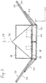
- eine Seitenansicht der Solarzellenanordnung gemäß
Fig. 1 , dabei ist ein vorderer Flügel nicht dargestellt, - Fig. 3:
- eine Draufsicht auf die Solarzellenanordnung gemäß
Fig. 1 , - Fig. 4:
- eine Seitenansicht wie
Fig. 3 , jedoch nun für ein 2. Ausführungsbeispiel mit Kugelkappe als zentralem Innenteil. - Für die Beschreibung der Solarzellenanordnung wird ein rechtshändiges, rechtwinkliges x-y-z-Koordinatensystem verwendet.
- Die Solarzellenanordnung hat eine Basis 20, die Basis 20 ist Tragvorrichtung für alle anderen Teile, auf die im Folgenden noch eingegangen wird. Sie kann Befestigungsvorrichtungen aufweisen, um die gesamte Anordnung auf beliebigen Unterlagen, beispielsweise einem Boden, zu befestigen. In den gezeigten Ausführungsbeispielen ist die Basis als Rohrrahmen ausgeführt, es werden Rohre mit Rechteckprofil verwendet. Die Basis ist ähnlich einer Palette für den Transport von Waren ausgebildet. Sie hat eine gewisse Höhe, die in z-Richtung bestimmt ist. Sie hat eine Oberseite, die in der x-y-Ebene liegt. Die Basis 20 ist den beiden Ausführungsbeispielen durch einen Quader begrenzt. Sie hat vier Seitenkanten 22, 24, die sich im Bereich einer Oberseite 26 befinden. Diese Oberseite 26 kann durch eine Platte realisiert sein, die den Rohrrahmen nach oben abschließt. Die Oberseite 26 kann aber auch offen sein oder es sind nur diejenigen Bereiche der Oberseite 26 bedeckt, die nach oben hin offen sind. Vorzugsweise ist die Basis 20 seitlich und unten offen, wie in beiden Ausführungsbeispielen gezeigt.
- Die Solarzellenanordnung hat eine zentrale Achse 28. Sie verläuft in z-Richtung und durch die Mitte der Oberseite 26. Die Solarzellenanordnung hat weiterhin ein zentrales Innenteil 30. Es befindet sich oberhalb der Basis 20 und ist mit dieser verbunden. Das zentrale Innenteil 30 hat einen Scheitelpunkt 32. Dieser ist der am weitesten von der Basis 20 entfernte Punkt des zentralen Innenteils 30. Er befindet sich auf der zentralen Achse 28. Im 1. Ausführungsbeispiel ist das zentrale Innenteil 30 eine regelmäßige vierseitige Pyramide mit quadratischer Grundfläche. Die Grundfläche entspricht der Fläche der Oberseite 26 der Basis 20. Im 2. Ausführungsbeispiel ist das zentrale Innenteil 30 eine Kugelkappe. Ihre Höhe liegt bei etwa 85 % des Radius der Kugel. Vorzugsweise wird eine Halbkugel verwendet. Die Kugelkappe hat eine Kappenhöhe, die vorzugsweise im Bereich von 50-100 % des Radius der Kugel liegen kann.
- Die Außenseite des zentralen Innenteils 30 ist mit Solarzellen 36 und Spiegeln 46 versehen. Hierzu wird insbesondere auf
Fig. 4 verwiesen. Diejenigen Bereiche der Außenseite, von denen eine Reflexion in Richtung der zentralen Achse 28 einfallenden Lichtes nicht zu einem Flügel 34 gelangen kann, sind vorzugsweise mit Solarzellen 36 belegt. Dies gilt insbesondere für diejenigen Bereiche, die in Nähe des Scheitelpunktes 32 sind. Andere Bereiche der Außenseite sind mit planen Stücken eines Spiegels 46 (ähnlich einer Discokugel) oder in der Wölbung verspiegelt, also eine Verspiegelung der gekrümmten Oberfläche des zentralen Innenteils 30. - An den vier Seitenkanten 22, 24 sind jeweils Flügel 34 um eine Schwenkachse 42 schwenkbar angelenkt. Die Flügel 34 sind rechteckförmig. Auf den Oberseiten der Flügel 34, die der zentralen Achse 28 zugewandt sind, sind die Flügel 34 mit Solarzellen 36 belegt. Sie sind möglichst vollflächig belegt. Wenn die Flügel 34 in die x-y-Ebene geklappt sind, befinden sich die Solarzellen 36 oben, sind also unmittelbar dem einfallenden Licht ausgesetzt. Jeder Flügel 34 ist mit einer Antriebsvorrichtung 38 verbunden, die Stellarme 40 für jeden einzelnen Flügel 34 hat. Diese Stellarme 40 sind an den Flügeln 34 und an einem unteren Teilbereich der Basis 20 angelenkt. Sie sind beispielsweise als Zylinder/Kolbeneinheit ausgebildet. In einer anderen Ausführung sind sie nur an den Flügeln 34 und nicht an der Basis 20 eingelenkt und mit weiteren Antriebsteilen, die hier nicht dargestellt sind, bewegungsverbunden. Die Antriebsvorrichtung 38 kann mechanisch und oder hydraulisch arbeiten. Wesentliche Teile der Antriebsvorrichtung 38 sind in einem Hohlraum unter dem zentralen Innenteil 30 angeordnet.
- Vorzugsweise hat die Antriebsvorrichtung 38 zwei Betriebszustände. In einem 1. Betriebszustand werden die Flügel 34 gleichzeitig und synchron verschwenkt. Der 1. Betriebszustand liegt vor, wenn die Solarzellenanordnung Licht empfängt und elektrische Leistung abgibt. Die Schwenkwinkel der Flügel 36 sind begrenzt auf maximal 120, vorzugsweise maximal 90° ausgehend von einer Position, in der die Flügel 36 in der x-y-Ebene liegen. Der 2. Betriebszustand ist für den Ruhe- oder Schutzzustand vorgesehen. In diesem Betriebszustand können die Flügel 36 gruppenweise oder auch einzeln bewegt werden. Zwei gegenüberliegende Flügel 36 werden in der Ausbildung nach dem 1. Ausführungsbeispiel soweit geschwenkt, bis sich ihre freien Enden berühren und ein Dach gebildet wird. Die beiden anderen Flügel 36 werden dann so weit hochgeklappt, dass die zentrale Achse 28 in ihrer Ebene liegt, dies ist bei ca. 90° gegeben.
- In beiden Ausführungsbeispielen ist der Abstand des Scheitelpunktes 32 von der Basis 20 kleiner als die Flügellänge der Flügel 34, gemessen von der Schwenkachse 22 bzw. 24 bis zum freien Ende. In anderen, nicht gezeigten Ausführungsbeispielen ist der Scheitelpunkt 32 weiter von der Basis 20 entfernt als die Flügellänge der Flügel 34 beträgt.
- Die Solarzellenanordnung nach beiden Ausführungsbeispielen ist jeweils drehsymmetrisch um 90°. Die Basis wird durch n=4 Seitenkanten 22,24 gebildet. Das zentrale Innenteil 30 im 1. Ausführungsbeispiel ist drehsymmetrisch um 90°. Die Kugelkappe im 2. Ausführungsbeispiel ist drehsymmetrisch um beliebige Drehwinkel. Die Drehwinkel beziehen sich jeweils auf Winkel um die zentrale Achse 28.
- Das zentrale Innenteil 30 hat eine Basisfläche. Sie verläuft parallel zur Oberseite 26. In der Regel ist das zentrale Innenteil 30 im Bereich seiner Basisfläche offen, also von unten aus zugänglich. Die Basisfläche kann aber auch physisch ausgebildet sein als Wand. Die Basisfläche hat Abmessungen, die gleich ausgerichteten Abmessungen der Basis 20 zu mehr als 80 %, insbesondere mehr als 90 % entsprechen. Die Basisfläche soll den zur Verfügung stehenden Platz auf der Oberseite 26 so weit wie möglich nutzen. Dies ist im 1. Ausführungsbeispiel vollständig der Fall.
- Die Solarzellenanordnung zur Erzeugung elektrischer Energie aus Licht mit mehreren Solarzellen 36, mit einer Basis 20, die mehrere Seitenkanten hat 22, 24, mit einer zentralen Achse 28, die quer zur Basis 20 verläuft, mit mehreren Flügeln 34, wobei jeweils ein Flügel 34 an einer Seitenkante 22, 24 der Basis 20 um eine Schwenkachse 42 schwenkbar angelenkt ist, wobei die Solarzellen 36 auf einer der zentralen Achse 28 zugewandten Oberseite der Flügel 34 angeordnet sind, hat eine Antriebsvorrichtung 38 zum Schwenken der Flügel 34 um ihre jeweilige Schwenkachse 42, und ein zentrales Innenteil 30, das auf der Basis 20 befestigt ist und das eine Außenfläche aufweist. Die Außenfläche ist mit Solarzellen 36 und/oder mit Spiegeln versehen. Das zentrale Innenteil 30 weist einen am weitesten von der Basis 20 entfernten Scheitelpunkt 32 auf, der auf der zentralen Achse liegt 28.
-
- 20
- Basis
- 22, 24
- Seitenkante
- 26
- Oberseite
- 28
- zentrale Achse
- 30
- zentrales Innenteil
- 32
- Scheitelpunkt
- 34
- Flügel
- 36
- Solarzelle
- 38
- Antriebsvorrichtung
- 40
- Stellarm
- 42
- Schwenkachse
- 44
- Steuervorrichtung
- 46
- Spiegel
Claims (11)
- Solarzellenanordnung zur Erzeugung elektrischer Energie aus Licht- mit mehreren Solarzellen (36),- mit einer Basis (20), die mehrere Seitenkanten hat (22, 24),- einer zentralen Achse (28), die quer zur Basis (20) verläuft,- mit mehreren Flügeln (34), wobei jeweils ein Flügel (34) an einer Seitenkante (22, 24) der Basis (20) um eine Schwenkachse (42) schwenkbar angelenkt ist,- die Solarzellen (36) sind auf einer der zentralen Achse (28) zugewandten Oberseite der Flügel (34) angeordnet,- mit einer Antriebsvorrichtung (38) zum Schwenken der Flügel (34) um ihre jeweilige Schwenkachse (42), und- mit einem zentralen Innenteil (30), das auf der Basis (20) befestigt ist, das Außenflächen aufweist, die mit Solarzellen (36) und/oder mit Spiegeln versehen sind,dadurch gekennzeichnet, dass das zentrale Innenteil (30) die Form einer Pyramide, eines Kegels oder einer Kugelkappe hat, dass das zentrale Innenteil (30) eine Basisfläche aufweist, welche Abmessungen hat, die gleichgerichteten Abmessungen der Basis (20) zu mehr als 80 % entsprechen, dass das zentrale Innenteil (30) einen am weitesten von der Basis (20) entfernten Scheitelpunkt (32) aufweist, der auf der zentralen Achse (28) liegt, und dass die einzelnen Flügel (34) ausgehend von einer Winkelposition, in der sie sich in der Ebene der Basis (20) befinden, zumindest bis zu einer Winkelposition schwenkbar sind, in der sie in Anlage am zentralen Innenteil (30) sind.
- Solarzellenanordnung nach Anspruch 1, dadurch gekennzeichnet, dass die Basis (20) ein Vieleck mit n gleichlangen Seitenkanten (22, 24) ist, und dass n Flügel (34) vorhanden sind, wobei n eine natürliche Zahl ist, vorzugsweise hat n den Wert 4 oder 6.
- Solarzellenanordnung nach einem der vorangegangenen Ansprüche,
dadurch gekennzeichnet, dass das zentrale Innenteil (30) eine Drehsymmetrie um die zentrale Achse aufweist, die 360°/n beträgt, wobei n die Anzahl der Seitenkanten (22, 24) der Basis (20) ist, die ein regelmäßiges Vieleck ist. - Solarzellenanordnung nach einem der vorangegangenen Ansprüche,
dadurch gekennzeichnet, dass das zentrale Innenteil (30) eine Basisfläche aufweist, welche Abmessungen hat, die gleichgerichteten Abmessungen der Basis (20) zu mehr als 90 % entsprechen. - Solarzellenanordnung nach einem der vorangegangenen Ansprüche,
dadurch gekennzeichnet, dass sie weiterhin eine Steuervorrichtung (44) aufweist, die in einem Innenraum des zentralen Innenteils (30) angeordnet ist. - Solarzellenanordnung nach einem der vorangegangenen Ansprüche,
dadurch gekennzeichnet, dass die Antriebsvorrichtung in einem Innenraum des zentralen Innenteils angeordnet ist. - Solarzellenanordnung nach einem der vorangegangenen Ansprüche,
dadurch gekennzeichnet, dass die Flügel (34) eine quer zu ihrer Schwenkachse (42) bestimmte Flügellänge aufweisen, die größer ist als der Abstand des Scheitelpunktes (32) des zentralen Innenteils (30) von der Basis (20). - Solarzellenanordnung nach einem der vorangegangenen Ansprüche,
dadurch gekennzeichnet, dass die Flügel (34) rechteckförmig sind. - Solarzellenanordnung nach einem der vorangegangenen Ansprüche,
dadurch gekennzeichnet, dass die Basis (20) ein regelmäßiges n-Eck mit n gleichlangen Seitenkanten (22, 24) ist, und dass die Winkel zwischen benachbarten Seitenkanten (22, 24) gleich sind. - Solarzellenanordnung nach einem der vorangegangenen Ansprüche,
dadurch gekennzeichnet, dass die Antriebsvorrichtung (38) in einem 1. Betriebszustand alle Flügel (34) gleichzeitig und synchron schwenkt. - Solarzellenanordnung nach einem der vorangegangenen Ansprüche,
dadurch gekennzeichnet, dass das zentrale Innenteil (30) innen hohl ist
Applications Claiming Priority (1)
| Application Number | Priority Date | Filing Date | Title |
|---|---|---|---|
| DE102016014342 | 2016-12-02 |
Publications (2)
| Publication Number | Publication Date |
|---|---|
| EP3331159A1 EP3331159A1 (de) | 2018-06-06 |
| EP3331159B1 true EP3331159B1 (de) | 2020-08-19 |
Family
ID=60543460
Family Applications (1)
| Application Number | Title | Priority Date | Filing Date |
|---|---|---|---|
| EP17204917.3A Active EP3331159B1 (de) | 2016-12-02 | 2017-12-01 | Solarzellenanordnung |
Country Status (2)
| Country | Link |
|---|---|
| EP (1) | EP3331159B1 (de) |
| ES (1) | ES2832564T3 (de) |
Cited By (1)
| Publication number | Priority date | Publication date | Assignee | Title |
|---|---|---|---|---|
| DE202023000086U1 (de) | 2023-01-04 | 2023-02-02 | Semen Zaitchik | Photovoltaik-Anlage mit spezieller Anordnung von Solarzellen |
Family Cites Families (9)
| Publication number | Priority date | Publication date | Assignee | Title |
|---|---|---|---|---|
| DE3005914A1 (de) | 1980-02-16 | 1981-09-10 | Werner H. Prof. Dr.-Ing. 7065 Winterbach Bloss | Solarzellenanordnung |
| EP1601022A1 (de) * | 2004-05-28 | 2005-11-30 | Hilber Technic Cooperation GmbH | Solaranlage |
| DE102007023583A1 (de) | 2007-05-21 | 2008-11-27 | Solartec Ag | Photovoltaik-Vorrichtung mit optischen Elementen zum Umlenken einfallender Sonnenstrahlen in einem gegebenen Spektralbereich auf an den optischen Elementen seitlich angebrachte Solarzellen |
| DE102007054323A1 (de) | 2007-11-14 | 2009-07-16 | Solartec Ag | Photovoltaik-Vorrichtung mit mindestens einem mindestens eine Lichtumwandlerschicht aufweisenden optischen Element mit mindestens einer seitlich angebrachten Solarzelle |
| ITRM20100015U1 (it) * | 2010-02-04 | 2011-08-05 | Pro D3 S R L | Gruppo elettrogeno solare mobile |
| ITRM20110561A1 (it) * | 2011-10-25 | 2013-04-26 | Pro D3 S R L | Gruppo elettrogeno solare mobile a pannelli dispiegantisi |
| FR2988221A1 (fr) * | 2012-03-15 | 2013-09-20 | Remy Peyrat | Dispositif autonome de production et de stockage d'energie photovoltaïque tractable pour sites isoles |
| AT513032B1 (de) * | 2012-09-04 | 2014-01-15 | HBT ENERGIETECHNIK GmbH | Multifunktionales, transportables Gebäude |
| DE202013003101U1 (de) | 2013-03-22 | 2013-06-18 | Thomas Gerlach | Photovoltaikvorrichtung |
-
2017
- 2017-12-01 EP EP17204917.3A patent/EP3331159B1/de active Active
- 2017-12-01 ES ES17204917T patent/ES2832564T3/es active Active
Non-Patent Citations (1)
| Title |
|---|
| None * |
Cited By (1)
| Publication number | Priority date | Publication date | Assignee | Title |
|---|---|---|---|---|
| DE202023000086U1 (de) | 2023-01-04 | 2023-02-02 | Semen Zaitchik | Photovoltaik-Anlage mit spezieller Anordnung von Solarzellen |
Also Published As
| Publication number | Publication date |
|---|---|
| EP3331159A1 (de) | 2018-06-06 |
| ES2832564T3 (es) | 2021-06-10 |
Similar Documents
| Publication | Publication Date | Title |
|---|---|---|
| AT509886B1 (de) | Solarmodul | |
| EP2669594B1 (de) | Solaranlage | |
| DE2550194A1 (de) | Anordnung fuer das konzentrieren und sammeln von sonnenenergie mit sonnennachstell- und sonnenenergiefeststell- steueranordnung sowie zugeordnetes verfahren | |
| DE102009042092A1 (de) | Solaranlage | |
| AT512680A1 (de) | Solarmodul | |
| EP2669596A1 (de) | Solaranlage | |
| DE102005055258B4 (de) | Verfahren zur Steuerung einer Montierung für eine Gruppe von Solarmodulen | |
| WO2010130727A1 (de) | Ausrichtbares fundamentsystem für solarpaneele | |
| DE10192244B4 (de) | Nachführvorrichtung | |
| EP2136156A2 (de) | Nachführeinrichtung zur Anpassung der Ausrichtung eines Traggestells an den Sonnenstand | |
| EP3331159A1 (de) | Solarzellenanordnung | |
| EP2218980A2 (de) | Unterstützungsvorrichtung, Steuereinrichtung und Verfahren zum Unterstützen einer Energiegewinnung aus Sonnenlicht | |
| DE102012000377A1 (de) | Windkraftanlage | |
| DE102010004905A1 (de) | Nachführsystem für Solarmodule | |
| DE102009022876A1 (de) | Nachführeinheit sowie Sonnenkollektor- oder Photovoltaikeinheit | |
| DE202009005123U1 (de) | Solarelement | |
| DE102006054531B4 (de) | Temperaturstabile Photovoltaikanlage in palmenähnlichem Erscheinungsbild | |
| WO2017144053A1 (de) | Anlage zur gewinnung von nutzenergie aus sonnen- und windenergie | |
| EP2881997B1 (de) | Anordnung zur Nutzung von Sonnenenergie | |
| DE102006028932A1 (de) | Photovoltaikmodul | |
| AT512944B1 (de) | Stellmechanismus zum Ausrichten der Spiegel eines konzentrierenden Solar-Kollektor-Systems und Solar-Kollektor-System | |
| DE102010028027A1 (de) | Sensorvorrichtung und Vorrichtung zur Umwandlung von Sonnenlicht in eine andere Energieform | |
| DE112021006127T5 (de) | Surya-sonnensystem | |
| DE212011100141U1 (de) | Solaranlage zur Energieertragerhöhung von Photovoltaik und photothermischer Systeme | |
| WO2012164003A2 (de) | Solareinrichtung mit reflektorvorrichtung und reflektorvorrichtung |
Legal Events
| Date | Code | Title | Description |
|---|---|---|---|
| PUAI | Public reference made under article 153(3) epc to a published international application that has entered the european phase |
Free format text: ORIGINAL CODE: 0009012 |
|
| STAA | Information on the status of an ep patent application or granted ep patent |
Free format text: STATUS: THE APPLICATION HAS BEEN PUBLISHED |
|
| AK | Designated contracting states |
Kind code of ref document: A1 Designated state(s): AL AT BE BG CH CY CZ DE DK EE ES FI FR GB GR HR HU IE IS IT LI LT LU LV MC MK MT NL NO PL PT RO RS SE SI SK SM TR |
|
| AX | Request for extension of the european patent |
Extension state: BA ME |
|
| STAA | Information on the status of an ep patent application or granted ep patent |
Free format text: STATUS: REQUEST FOR EXAMINATION WAS MADE |
|
| 17P | Request for examination filed |
Effective date: 20181123 |
|
| RBV | Designated contracting states (corrected) |
Designated state(s): AL AT BE BG CH CY CZ DE DK EE ES FI FR GB GR HR HU IE IS IT LI LT LU LV MC MK MT NL NO PL PT RO RS SE SI SK SM TR |
|
| STAA | Information on the status of an ep patent application or granted ep patent |
Free format text: STATUS: EXAMINATION IS IN PROGRESS |
|
| 17Q | First examination report despatched |
Effective date: 20191014 |
|
| GRAP | Despatch of communication of intention to grant a patent |
Free format text: ORIGINAL CODE: EPIDOSNIGR1 |
|
| STAA | Information on the status of an ep patent application or granted ep patent |
Free format text: STATUS: GRANT OF PATENT IS INTENDED |
|
| INTG | Intention to grant announced |
Effective date: 20200406 |
|
| GRAS | Grant fee paid |
Free format text: ORIGINAL CODE: EPIDOSNIGR3 |
|
| GRAA | (expected) grant |
Free format text: ORIGINAL CODE: 0009210 |
|
| STAA | Information on the status of an ep patent application or granted ep patent |
Free format text: STATUS: THE PATENT HAS BEEN GRANTED |
|
| AK | Designated contracting states |
Kind code of ref document: B1 Designated state(s): AL AT BE BG CH CY CZ DE DK EE ES FI FR GB GR HR HU IE IS IT LI LT LU LV MC MK MT NL NO PL PT RO RS SE SI SK SM TR |
|
| REG | Reference to a national code |
Ref country code: CH Ref legal event code: EP |
|
| REG | Reference to a national code |
Ref country code: DE Ref legal event code: R096 Ref document number: 502017006799 Country of ref document: DE |
|
| REG | Reference to a national code |
Ref country code: AT Ref legal event code: REF Ref document number: 1305104 Country of ref document: AT Kind code of ref document: T Effective date: 20200915 |
|
| REG | Reference to a national code |
Ref country code: IE Ref legal event code: FG4D Free format text: LANGUAGE OF EP DOCUMENT: GERMAN |
|
| REG | Reference to a national code |
Ref country code: LT Ref legal event code: MG4D |
|
| REG | Reference to a national code |
Ref country code: NL Ref legal event code: MP Effective date: 20200819 |
|
| PG25 | Lapsed in a contracting state [announced via postgrant information from national office to epo] |
Ref country code: NO Free format text: LAPSE BECAUSE OF FAILURE TO SUBMIT A TRANSLATION OF THE DESCRIPTION OR TO PAY THE FEE WITHIN THE PRESCRIBED TIME-LIMIT Effective date: 20201119 Ref country code: PT Free format text: LAPSE BECAUSE OF FAILURE TO SUBMIT A TRANSLATION OF THE DESCRIPTION OR TO PAY THE FEE WITHIN THE PRESCRIBED TIME-LIMIT Effective date: 20201221 Ref country code: FI Free format text: LAPSE BECAUSE OF FAILURE TO SUBMIT A TRANSLATION OF THE DESCRIPTION OR TO PAY THE FEE WITHIN THE PRESCRIBED TIME-LIMIT Effective date: 20200819 Ref country code: GR Free format text: LAPSE BECAUSE OF FAILURE TO SUBMIT A TRANSLATION OF THE DESCRIPTION OR TO PAY THE FEE WITHIN THE PRESCRIBED TIME-LIMIT Effective date: 20201120 Ref country code: LT Free format text: LAPSE BECAUSE OF FAILURE TO SUBMIT A TRANSLATION OF THE DESCRIPTION OR TO PAY THE FEE WITHIN THE PRESCRIBED TIME-LIMIT Effective date: 20200819 Ref country code: HR Free format text: LAPSE BECAUSE OF FAILURE TO SUBMIT A TRANSLATION OF THE DESCRIPTION OR TO PAY THE FEE WITHIN THE PRESCRIBED TIME-LIMIT Effective date: 20200819 Ref country code: SE Free format text: LAPSE BECAUSE OF FAILURE TO SUBMIT A TRANSLATION OF THE DESCRIPTION OR TO PAY THE FEE WITHIN THE PRESCRIBED TIME-LIMIT Effective date: 20200819 Ref country code: BG Free format text: LAPSE BECAUSE OF FAILURE TO SUBMIT A TRANSLATION OF THE DESCRIPTION OR TO PAY THE FEE WITHIN THE PRESCRIBED TIME-LIMIT Effective date: 20201119 |
|
| PG25 | Lapsed in a contracting state [announced via postgrant information from national office to epo] |
Ref country code: IS Free format text: LAPSE BECAUSE OF FAILURE TO SUBMIT A TRANSLATION OF THE DESCRIPTION OR TO PAY THE FEE WITHIN THE PRESCRIBED TIME-LIMIT Effective date: 20201219 Ref country code: PL Free format text: LAPSE BECAUSE OF FAILURE TO SUBMIT A TRANSLATION OF THE DESCRIPTION OR TO PAY THE FEE WITHIN THE PRESCRIBED TIME-LIMIT Effective date: 20200819 Ref country code: LV Free format text: LAPSE BECAUSE OF FAILURE TO SUBMIT A TRANSLATION OF THE DESCRIPTION OR TO PAY THE FEE WITHIN THE PRESCRIBED TIME-LIMIT Effective date: 20200819 Ref country code: RS Free format text: LAPSE BECAUSE OF FAILURE TO SUBMIT A TRANSLATION OF THE DESCRIPTION OR TO PAY THE FEE WITHIN THE PRESCRIBED TIME-LIMIT Effective date: 20200819 Ref country code: NL Free format text: LAPSE BECAUSE OF FAILURE TO SUBMIT A TRANSLATION OF THE DESCRIPTION OR TO PAY THE FEE WITHIN THE PRESCRIBED TIME-LIMIT Effective date: 20200819 |
|
| PG25 | Lapsed in a contracting state [announced via postgrant information from national office to epo] |
Ref country code: SM Free format text: LAPSE BECAUSE OF FAILURE TO SUBMIT A TRANSLATION OF THE DESCRIPTION OR TO PAY THE FEE WITHIN THE PRESCRIBED TIME-LIMIT Effective date: 20200819 Ref country code: EE Free format text: LAPSE BECAUSE OF FAILURE TO SUBMIT A TRANSLATION OF THE DESCRIPTION OR TO PAY THE FEE WITHIN THE PRESCRIBED TIME-LIMIT Effective date: 20200819 Ref country code: RO Free format text: LAPSE BECAUSE OF FAILURE TO SUBMIT A TRANSLATION OF THE DESCRIPTION OR TO PAY THE FEE WITHIN THE PRESCRIBED TIME-LIMIT Effective date: 20200819 Ref country code: CZ Free format text: LAPSE BECAUSE OF FAILURE TO SUBMIT A TRANSLATION OF THE DESCRIPTION OR TO PAY THE FEE WITHIN THE PRESCRIBED TIME-LIMIT Effective date: 20200819 Ref country code: DK Free format text: LAPSE BECAUSE OF FAILURE TO SUBMIT A TRANSLATION OF THE DESCRIPTION OR TO PAY THE FEE WITHIN THE PRESCRIBED TIME-LIMIT Effective date: 20200819 |
|
| REG | Reference to a national code |
Ref country code: DE Ref legal event code: R097 Ref document number: 502017006799 Country of ref document: DE |
|
| PG25 | Lapsed in a contracting state [announced via postgrant information from national office to epo] |
Ref country code: AL Free format text: LAPSE BECAUSE OF FAILURE TO SUBMIT A TRANSLATION OF THE DESCRIPTION OR TO PAY THE FEE WITHIN THE PRESCRIBED TIME-LIMIT Effective date: 20200819 |
|
| REG | Reference to a national code |
Ref country code: ES Ref legal event code: FG2A Ref document number: 2832564 Country of ref document: ES Kind code of ref document: T3 Effective date: 20210610 |
|
| PLBE | No opposition filed within time limit |
Free format text: ORIGINAL CODE: 0009261 |
|
| STAA | Information on the status of an ep patent application or granted ep patent |
Free format text: STATUS: NO OPPOSITION FILED WITHIN TIME LIMIT |
|
| PG25 | Lapsed in a contracting state [announced via postgrant information from national office to epo] |
Ref country code: SK Free format text: LAPSE BECAUSE OF FAILURE TO SUBMIT A TRANSLATION OF THE DESCRIPTION OR TO PAY THE FEE WITHIN THE PRESCRIBED TIME-LIMIT Effective date: 20200819 |
|
| 26N | No opposition filed |
Effective date: 20210520 |
|
| PG25 | Lapsed in a contracting state [announced via postgrant information from national office to epo] |
Ref country code: IT Free format text: LAPSE BECAUSE OF FAILURE TO SUBMIT A TRANSLATION OF THE DESCRIPTION OR TO PAY THE FEE WITHIN THE PRESCRIBED TIME-LIMIT Effective date: 20200819 |
|
| REG | Reference to a national code |
Ref country code: CH Ref legal event code: PL |
|
| PG25 | Lapsed in a contracting state [announced via postgrant information from national office to epo] |
Ref country code: SI Free format text: LAPSE BECAUSE OF FAILURE TO SUBMIT A TRANSLATION OF THE DESCRIPTION OR TO PAY THE FEE WITHIN THE PRESCRIBED TIME-LIMIT Effective date: 20200819 Ref country code: MC Free format text: LAPSE BECAUSE OF FAILURE TO SUBMIT A TRANSLATION OF THE DESCRIPTION OR TO PAY THE FEE WITHIN THE PRESCRIBED TIME-LIMIT Effective date: 20200819 |
|
| REG | Reference to a national code |
Ref country code: BE Ref legal event code: MM Effective date: 20201231 |
|
| PG25 | Lapsed in a contracting state [announced via postgrant information from national office to epo] |
Ref country code: LU Free format text: LAPSE BECAUSE OF NON-PAYMENT OF DUE FEES Effective date: 20201201 Ref country code: IE Free format text: LAPSE BECAUSE OF NON-PAYMENT OF DUE FEES Effective date: 20201201 |
|
| PG25 | Lapsed in a contracting state [announced via postgrant information from national office to epo] |
Ref country code: CH Free format text: LAPSE BECAUSE OF NON-PAYMENT OF DUE FEES Effective date: 20201231 Ref country code: LI Free format text: LAPSE BECAUSE OF NON-PAYMENT OF DUE FEES Effective date: 20201231 |
|
| PG25 | Lapsed in a contracting state [announced via postgrant information from national office to epo] |
Ref country code: TR Free format text: LAPSE BECAUSE OF FAILURE TO SUBMIT A TRANSLATION OF THE DESCRIPTION OR TO PAY THE FEE WITHIN THE PRESCRIBED TIME-LIMIT Effective date: 20200819 Ref country code: MT Free format text: LAPSE BECAUSE OF FAILURE TO SUBMIT A TRANSLATION OF THE DESCRIPTION OR TO PAY THE FEE WITHIN THE PRESCRIBED TIME-LIMIT Effective date: 20200819 Ref country code: CY Free format text: LAPSE BECAUSE OF FAILURE TO SUBMIT A TRANSLATION OF THE DESCRIPTION OR TO PAY THE FEE WITHIN THE PRESCRIBED TIME-LIMIT Effective date: 20200819 |
|
| PG25 | Lapsed in a contracting state [announced via postgrant information from national office to epo] |
Ref country code: MK Free format text: LAPSE BECAUSE OF FAILURE TO SUBMIT A TRANSLATION OF THE DESCRIPTION OR TO PAY THE FEE WITHIN THE PRESCRIBED TIME-LIMIT Effective date: 20200819 |
|
| PG25 | Lapsed in a contracting state [announced via postgrant information from national office to epo] |
Ref country code: BE Free format text: LAPSE BECAUSE OF NON-PAYMENT OF DUE FEES Effective date: 20201231 |
|
| GBPC | Gb: european patent ceased through non-payment of renewal fee |
Effective date: 20211201 |
|
| PG25 | Lapsed in a contracting state [announced via postgrant information from national office to epo] |
Ref country code: GB Free format text: LAPSE BECAUSE OF NON-PAYMENT OF DUE FEES Effective date: 20211201 |
|
| PGFP | Annual fee paid to national office [announced via postgrant information from national office to epo] |
Ref country code: FR Payment date: 20231220 Year of fee payment: 7 Ref country code: DE Payment date: 20231214 Year of fee payment: 7 |
|
| REG | Reference to a national code |
Ref country code: AT Ref legal event code: MM01 Ref document number: 1305104 Country of ref document: AT Kind code of ref document: T Effective date: 20221201 |
|
| PGFP | Annual fee paid to national office [announced via postgrant information from national office to epo] |
Ref country code: ES Payment date: 20240118 Year of fee payment: 7 |
|
| PG25 | Lapsed in a contracting state [announced via postgrant information from national office to epo] |
Ref country code: AT Free format text: LAPSE BECAUSE OF NON-PAYMENT OF DUE FEES Effective date: 20221201 |
|
| PG25 | Lapsed in a contracting state [announced via postgrant information from national office to epo] |
Ref country code: AT Free format text: LAPSE BECAUSE OF NON-PAYMENT OF DUE FEES Effective date: 20221201 |
|
| REG | Reference to a national code |
Ref country code: DE Ref legal event code: R119 Ref document number: 502017006799 Country of ref document: DE |
|
| PG25 | Lapsed in a contracting state [announced via postgrant information from national office to epo] |
Ref country code: DE Free format text: LAPSE BECAUSE OF NON-PAYMENT OF DUE FEES Effective date: 20250701 |
|
| PG25 | Lapsed in a contracting state [announced via postgrant information from national office to epo] |
Ref country code: FR Free format text: LAPSE BECAUSE OF NON-PAYMENT OF DUE FEES Effective date: 20241231 |
|
| REG | Reference to a national code |
Ref country code: ES Ref legal event code: FD2A Effective date: 20260126 |
|
| PG25 | Lapsed in a contracting state [announced via postgrant information from national office to epo] |
Ref country code: ES Free format text: LAPSE BECAUSE OF NON-PAYMENT OF DUE FEES Effective date: 20241202 |
|
| PGFP | Annual fee paid to national office [announced via postgrant information from national office to epo] |
Ref country code: AT Payment date: 20260410 Year of fee payment: 5 |