EP3331128B1 - Wireless power feeding unit, power transmitting module, power receiving module, and wireless power transmission system - Google Patents
Wireless power feeding unit, power transmitting module, power receiving module, and wireless power transmission system Download PDFInfo
- Publication number
- EP3331128B1 EP3331128B1 EP17204419.0A EP17204419A EP3331128B1 EP 3331128 B1 EP3331128 B1 EP 3331128B1 EP 17204419 A EP17204419 A EP 17204419A EP 3331128 B1 EP3331128 B1 EP 3331128B1
- Authority
- EP
- European Patent Office
- Prior art keywords
- power
- circuit
- transmission
- load
- feeding unit
- Prior art date
- Legal status (The legal status is an assumption and is not a legal conclusion. Google has not performed a legal analysis and makes no representation as to the accuracy of the status listed.)
- Active
Links
Images


Classifications
-
- H—ELECTRICITY
- H02—GENERATION; CONVERSION OR DISTRIBUTION OF ELECTRIC POWER
- H02J—CIRCUIT ARRANGEMENTS OR SYSTEMS FOR SUPPLYING OR DISTRIBUTING ELECTRIC POWER; SYSTEMS FOR STORING ELECTRIC ENERGY
- H02J50/00—Circuit arrangements or systems for wireless supply or distribution of electric power
- H02J50/70—Circuit arrangements or systems for wireless supply or distribution of electric power involving the reduction of electric, magnetic or electromagnetic leakage fields
-
- H—ELECTRICITY
- H02—GENERATION; CONVERSION OR DISTRIBUTION OF ELECTRIC POWER
- H02J—CIRCUIT ARRANGEMENTS OR SYSTEMS FOR SUPPLYING OR DISTRIBUTING ELECTRIC POWER; SYSTEMS FOR STORING ELECTRIC ENERGY
- H02J50/00—Circuit arrangements or systems for wireless supply or distribution of electric power
- H02J50/10—Circuit arrangements or systems for wireless supply or distribution of electric power using inductive coupling
-
- B—PERFORMING OPERATIONS; TRANSPORTING
- B25—HAND TOOLS; PORTABLE POWER-DRIVEN TOOLS; MANIPULATORS
- B25J—MANIPULATORS; CHAMBERS PROVIDED WITH MANIPULATION DEVICES
- B25J19/00—Accessories fitted to manipulators, e.g. for monitoring, for viewing; Safety devices combined with or specially adapted for use in connection with manipulators
- B25J19/0025—Means for supplying energy to the end effector
- B25J19/0045—Contactless power transmission, e.g. by magnetic induction
-
- B—PERFORMING OPERATIONS; TRANSPORTING
- B25—HAND TOOLS; PORTABLE POWER-DRIVEN TOOLS; MANIPULATORS
- B25J—MANIPULATORS; CHAMBERS PROVIDED WITH MANIPULATION DEVICES
- B25J9/00—Programme-controlled manipulators
- B25J9/10—Programme-controlled manipulators characterised by positioning means for manipulator elements
- B25J9/12—Programme-controlled manipulators characterised by positioning means for manipulator elements electric
-
- H—ELECTRICITY
- H01—ELECTRIC ELEMENTS
- H01F—MAGNETS; INDUCTANCES; TRANSFORMERS; SELECTION OF MATERIALS FOR THEIR MAGNETIC PROPERTIES
- H01F38/00—Adaptations of transformers or inductances for specific applications or functions
- H01F38/14—Inductive couplings
-
- H—ELECTRICITY
- H02—GENERATION; CONVERSION OR DISTRIBUTION OF ELECTRIC POWER
- H02J—CIRCUIT ARRANGEMENTS OR SYSTEMS FOR SUPPLYING OR DISTRIBUTING ELECTRIC POWER; SYSTEMS FOR STORING ELECTRIC ENERGY
- H02J50/00—Circuit arrangements or systems for wireless supply or distribution of electric power
- H02J50/10—Circuit arrangements or systems for wireless supply or distribution of electric power using inductive coupling
- H02J50/12—Circuit arrangements or systems for wireless supply or distribution of electric power using inductive coupling of the resonant type
-
- H—ELECTRICITY
- H02—GENERATION; CONVERSION OR DISTRIBUTION OF ELECTRIC POWER
- H02J—CIRCUIT ARRANGEMENTS OR SYSTEMS FOR SUPPLYING OR DISTRIBUTING ELECTRIC POWER; SYSTEMS FOR STORING ELECTRIC ENERGY
- H02J50/00—Circuit arrangements or systems for wireless supply or distribution of electric power
- H02J50/40—Circuit arrangements or systems for wireless supply or distribution of electric power using two or more transmitting or receiving devices
- H02J50/402—Circuit arrangements or systems for wireless supply or distribution of electric power using two or more transmitting or receiving devices the two or more transmitting or the two or more receiving devices being integrated in the same unit, e.g. power mats with several coils or antennas with several sub-antennas
-
- H—ELECTRICITY
- H02—GENERATION; CONVERSION OR DISTRIBUTION OF ELECTRIC POWER
- H02J—CIRCUIT ARRANGEMENTS OR SYSTEMS FOR SUPPLYING OR DISTRIBUTING ELECTRIC POWER; SYSTEMS FOR STORING ELECTRIC ENERGY
- H02J50/00—Circuit arrangements or systems for wireless supply or distribution of electric power
- H02J50/80—Circuit arrangements or systems for wireless supply or distribution of electric power involving the exchange of data, concerning supply or distribution of electric power, between transmitting devices and receiving devices
-
- H—ELECTRICITY
- H02—GENERATION; CONVERSION OR DISTRIBUTION OF ELECTRIC POWER
- H02P—CONTROL OR REGULATION OF ELECTRIC MOTORS, ELECTRIC GENERATORS OR DYNAMO-ELECTRIC CONVERTERS; CONTROLLING TRANSFORMERS, REACTORS OR CHOKE COILS
- H02P27/00—Arrangements or methods for the control of AC motors characterised by the kind of supply voltage
- H02P27/04—Arrangements or methods for the control of AC motors characterised by the kind of supply voltage using variable-frequency supply voltage, e.g. inverter or converter supply voltage
- H02P27/06—Arrangements or methods for the control of AC motors characterised by the kind of supply voltage using variable-frequency supply voltage, e.g. inverter or converter supply voltage using dc to ac converters or inverters
-
- H—ELECTRICITY
- H02—GENERATION; CONVERSION OR DISTRIBUTION OF ELECTRIC POWER
- H02P—CONTROL OR REGULATION OF ELECTRIC MOTORS, ELECTRIC GENERATORS OR DYNAMO-ELECTRIC CONVERTERS; CONTROLLING TRANSFORMERS, REACTORS OR CHOKE COILS
- H02P3/00—Arrangements for stopping or slowing electric motors, generators, or dynamo-electric converters
- H02P3/06—Arrangements for stopping or slowing electric motors, generators, or dynamo-electric converters for stopping or slowing an individual dynamo-electric motor or dynamo-electric converter
- H02P3/18—Arrangements for stopping or slowing electric motors, generators, or dynamo-electric converters for stopping or slowing an individual dynamo-electric motor or dynamo-electric converter for stopping or slowing an ac motor
Definitions
- the present disclosure relates to a wireless power feeding unit, a power transmitting module, a power receiving module, and a wireless power transmission system.
- Electrically operated apparatuses e.g., robot hand apparatuses which perform various operations by using an end effector(s) connected to the leading end(s) of one or more arms are being developed.
- Such electrically operated apparatuses are utilized in various kinds of work, such as carrying articles at a factory.
- Japanese Laid-Open Patent Publication No. 2015-104764 discloses a vertical articulated type robot apparatus in which a plurality of frames are coupled in series via a plurality of joints that are capable of rotation.
- electric power is supplied via cables to the rotary mechanism in each joint and to the end effector at the leading end of the arm.
- US 2014/0354073 discloses a wireless power transmission system with a separate transmission part for information controlling the load.
- US 2012/0146580 discloses a wireless power transmission system with a separate transmission part for load (battery) info fed back to the transmitter.
- the info is transferred using coils.
- the present disclosure provides a novel wireless power transmission technique which improves the work efficiency in an electrically operated apparatus, e.g., a robot, that has a movable section(s).
- a wireless power feeding unit includes a power transmitting module and a power receiving module.
- the power transmitting module includes: a first inverter circuit which is connected to a power source via a switch, and which converts supplied electric power into first AC power and outputs the first AC power; a first transmission coil which is connected to the first inverter circuit, and which sends out the first AC power; a second inverter circuit which is connected to the power source or another power source not via the switch, and which converts supplied electric power into second AC power and outputs the second AC power; a second transmission coil which is connected to the second inverter circuit, and which sends out the second AC power; and a power transmission control circuit which is connected to the power source or another power source not via the switch, and which controls the first and second inverter circuits.
- the power receiving module includes: a first reception coil which is opposed to the first transmission coil, and which receives at least a portion of the first AC power; and a second reception coil which is opposed to the second transmission coil, and which receives at least a portion of the second AC power. At least a portion of the AC power received by the first reception coil is supplied to a load. At least a portion of the AC power received by the second reception coil is supplied to a load control circuit which controls the load. During operation of the first and second inverter circuits, even if the switch is turned OFF to stop supply of power to the first inverter circuit, the power transmission control circuit maintains control of the second inverter circuit.
- the work efficiency in an apparatus that has a movable section(s), e.g., a robot can be improved.
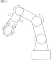
- FIG. 1 is a diagram schematically showing an example of a robot arm apparatus having a plurality of movable sections (e.g., joints). Each movable section is constructed so as to be capable of rotation or expansion/contraction by means of an actuator that includes an electric motor (which hereinafter may simply be referred to as a "motor").
- an electric motor which hereinafter may simply be referred to as a "motor”
- it is necessary to individually supply electric power to the plurality of motors and control them.
- Supply of power from a power source to the plurality of motors has conventionally been achieved via a multitude of cables.
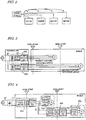
- FIG. 2 is a diagram schematically showing such a conventional construction.
- electric power is supplied from a power source to a plurality of motors via wired bus connections.
- Each motor is controlled by a control device (controller) not shown.
- FIG. 3 is a diagram showing a specific example of the conventional construction shown in FIG. 2 .
- a robot in this example has two joints. Each joint is driven by a servo motor M. Each servo motor M is driven with a three-phase current.
- a controller includes as many motor driving circuits 900 as there are motors M to be controlled.
- Each motor driving circuit 900 includes a converter, a three phase inverter, and a control circuit.
- the converter converts alternating current (AC) power from a power source into direct current (DC) power.
- the three phase inverter converts the DC power which is output from the converter into a three-phase AC power, and supplies it to the motor M.
- the control circuit controls the three phase inverter to supply necessary power to the motor M.
- the motor driving circuit 900 obtains information concerning rotary position and rotational speed from the motor M , and adjusts the voltage of each phase based on this information. Such construction allows the operation of each joint to be controlled.
- FIG. 4 is a diagram showing an exemplary robot in which power transmission in each joint is achieved wirelessly.
- a three phase inverter and a control circuit to drive each motor M are provided within the robot, rather than in an external controller.
- wireless power transmission is performed by utilizing magnetic field coupling between a transmission coil and a reception coil.
- this robot includes a wireless power feeding unit 600 and an electromechanical motor 700.
- Each electromechanical motor 700 includes a motor M , a three phase inverter, and a control circuit.
- Each wireless power feeding unit 600 includes a power transmitting circuit (also referred to as a "power transmitter"), a transmission coil, a reception coil, and a power receiving circuit (also referred to as a "power receiver").
- the power transmitting circuit includes an inverter circuit.
- the power receiving circuit includes a rectifier circuit.
- the power transmitting circuit in the left wireless power feeding unit 600 shown in FIG. 4 which is connected between a power source and the transmission coil, converts the supplied DC power into AC power, and supplies it to the transmission coil.
- the power receiving circuit converts the AC power which the reception coil has received from the transmission coil into DC power, and outputs it.
- the DC power which has been output from the power receiving circuit is supplied not only to the electromechanical motor 700, but also the power transmitting circuit in the wireless power feeding unit 600 in any other joint. In this manner, electric power is also supplied to the electromechanical motors 700 driving the other joints.
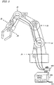
- FIG. 5 is a diagram showing an example of a robot arm apparatus in which the above-described wireless power transmission is applied.
- This robot arm apparatus has joints J1 to J6 .
- the above-described wireless power transmission is applied to the joints J2 and J4.
- conventional wired power transmission is applied to the joints J1, J3, J5, and J6.
- the robot arm apparatus includes: a plurality of motors M1 to M6 which respectively drive the joints J1 to J6; motor control circuits Ctr3 to Ctr6 which respectively control the motors M3 to M6 among the motors M1 to M6; and two wireless power feeding units (intelligent robot harness units; also referred to as IHUs) IHU2 and IHU4 which are respectively provided in the joints J2 and J4.
- Motor control circuits Ctr1 and Ctr2 which respectively drive the motors M1 and M2 are provided in a control device 500 which is external to the robot.
- the control device 500 supplies electric power to the motors M1 and M2 and the wireless power feeding unit IHU2 in a wired manner.
- the wireless power feeding unit IHU2 wirelessly transmits electric power via a pair of coils.
- the transmitted electric power is then supplied to the motors M3 and M4, the control circuits Ctr3 and Ctr4, and the wireless power feeding unit IHU4.
- the wireless power feeding unit IHU4 also wirelessly transmits electric power via a pair of coils in the joint J4.
- the transmitted electric power is supplied to the motors M5 and M6 and the control circuits Ctr5 and Ctr6.
- FIG. 5 needs to have a switch for emergency stop. More specifically, there are standards stipulating that a switch for making an emergency stop (a push button) needs to be provided, such that the switch has a direct opening mechanism.
- a direct opening mechanism is a structure where a normally-closed (NC) contact is opened with the force by which a button is pressed, thereby cutting a current flow.
- the example shown in FIG. 5 includes a switch 400 for emergency stop being provided between the control device 500 and the robot, the switch having a direct opening mechanism. By pressing the switch 400 (i.e., OFF), supply of power to each motor of the robot is forcedly cut, whereby the robot can be safely stopped.
- the inventors have found the aforementioned problems, and sought for constructions for solving these problems.
- the inventors have arrived at a novel construction, thereby accomplishing the technique according to the present disclosure, which, even after supply of power to a load such as a motor is stopped with an emergency stop switch, maintains supply of power to a load control circuit that controls the load.
- the technique according to the present disclosure will be described in outline.
- a wireless power feeding unit includes:
- the first inverter circuit which generates electric power to be supplied to the load (which may hereinafter be referred to as "power for driving purposes” or “drive power”) is connected to the power source via the switch.
- the second inverter circuit which generates electric power to be supplied to the load control circuit (which may hereinafter be referred to as “power for control purposes” or “control power”) and the power transmission control circuit are connected to the power source or another power source not via the switch.
- a “load” means any device that may operate with electric power.
- loads include devices such as motors, cameras (imaging devices), light sources, secondary batteries, and electronic circuits (e.g., power conversion circuits or microcontrollers).
- a device which includes a load and a circuit to control the load may be referred to as a "load device”.
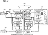
- FIG. 6 is a block diagram showing the construction of a wireless power transmission system according to illustrative Embodiment 1 of the present disclosure.
- this wireless power transmission system may be adopted in an electric machine, such as a robot arm apparatus used to carry articles in a factory.
- the wireless power transmission system according to the present embodiment includes a wireless power feeding unit 100, a power source 200 which is connected to the wireless power feeding unit 100, an emergency stop switch 400, an actuator (as one example of a load device) 300, and a controller (control device) 500.
- the power source 200, the switch 400, the controller 500, and the actuator 300 may be an external element to the wireless power transmission system.
- thick lines indicate supply lines of electric power
- arrows indicate supply lines of signals.
- the wireless power feeding unit 100 includes a power transmitting module 10 and a power receiving module 20.
- the power transmitting module 10 includes a first inverter circuit (also referred to as a “driving inverter”) 13, a first transmission coil 11, a second inverter circuit (also referred to as a “control inverter”) 14, a second transmission coil 12, a power transmission control circuit 15, and a first communication circuit 16.
- the driving inverter 13 which is connected to the power source 200 via the switch 400, converts supplied electric power into first AC power and outputs it.
- the first transmission coil 11, which is connected to the driving inverter 13, sends out the first AC power.
- the first communication circuit 16 is connected to the power source 200 not via the switch 400.
- the first communication circuit 16 sends a signal for controlling the motor 31 (as one example of a load) in the actuator 300.
- the signal for controlling the motor 31 may be a signal representing a command value of e.g. rotational speed of the motor 31, for example.
- the signal is supplied from the external controller 500 to the power transmitting module 10.
- the power receiving module 20 includes a first reception coil 21, a first rectifier circuit (also referred to as a “driving rectifier”) 23, a second reception coil 22, a second rectifier circuit (also referred to as a “control rectifier”) 24, a power reception control circuit 25, and a second communication circuit 26.
- the first reception coil 21 is opposed to the first transmission coil 11.
- the first reception coil 21 receives at least a portion of the first AC power which is sent out from the first transmission coil 11.
- the driving rectifier 23, which is connected to the first reception coil 21, converts the AC power received by the first reception coil 21 into first DC power and outputs it.
- the second reception coil 22 is opposed to the second transmission coil 12.
- the second reception coil 22 receives at least a portion of the second AC power which has been transmitted from the second transmission coil 12.
- the power reception control circuit 25 is driven by the second DC power output from the control rectifier 24, and controls the second communication circuit 26.
- the second communication circuit 26 performs communications between the first communication circuit 16 on the power transmission side and the motor control circuit 35 in the actuator 300.
- the second communication circuit 26 receives a signal which has been sent from the first communication circuit 16, and sends it to the motor control circuit 35.
- the second communication circuit 26 may send a signal with which to perform an operation of compensating for the load variation in the motor 31, for example, to the first communication circuit 16.
- the power transmission control circuit 15 can control the driving inverter 13 to adjust drive power. As a result, for example, an always-constant voltage may be given to the motor inverter 33 in the actuator 300.
- the actuator 300 causes the power receiving module 20 to move or rotate relative to the power transmitting module 10. During this operation, the first transmission coil 11 and the first reception coil 21 maintain an opposed state, and the second transmission coil 12 and the second reception coil 22 also maintain an opposed state.
- the actuator 300 includes a servo motor 31 which is driven by a three-phase current, and a motor amplifier 30 to drive the motor 31.
- the motor amplifier 30 includes: a motor inverter (motor driving circuit) 33 which converts the DC power having been output from the driving rectifier 23 into three-phase AC power, and supplies it to the motor 31; and a motor control circuit 35 which controls the motor inverter 33.
- the motor control circuit 35 detects information on rotary position and rotational speed by using e.g. a rotary encoder, and based on this information, controls the motor inverter 33 so as to realize a desired rotating operation.
- the motor 31 may not be a motor which is driven with a three-phase current.
- the motor 33 is a DC-driven motor, a motor driving circuit which is suited for that motor construction is to be used instead of a three phase inverter.
- At least a portion of the first DC power which is output from the driving rectifier 23 is supplied to the motor inverter 33.
- At least a portion of the second DC power which is output from the control rectifier 24 is supplied to the motor control circuit 35.
- the power transmission control circuit 15 performs power transmission control while monitoring the electric power which is supplied to the driving inverter 13. By detecting a decrease in the electric power value that is being input to the driving inverter 13, the power transmission control circuit 15 detects that the emergency stop switch 400 has been pressed (i.e., the switch 400 has been turned OFF). Upon detecting a decrease (or stop) of the supplied electric power, the power transmission control circuit 15 stops control of the driving inverter 13, while maintaining control of the control inverter 14. In the meantime, the power transmission control circuit 15 may instruct the communication circuit 16 to send a predetermined signal (e.g., a command to stop the motor) to the motor control circuit 35. Upon receiving this signal, the motor control circuit 35 can stop controlling the motor inverter 33. When electric power to the driving system is suspended, this prevents unnecessary inverter control from being continued.
- a predetermined signal e.g., a command to stop the motor
- electric power for motor control purposes is input independently of the electric power for motor driving purposes.
- electric power for control and communication purposes in the wireless power feeding unit 100 is input independently of the electric power for driving purposes.
- FIG. 7A is a diagram showing an exemplary equivalent circuit for the transmission coils 11 and 12 and the reception coils 21 and 22 in the wireless power feeding unit 100.
- each coil functions as a resonant circuit having an inductance component and a capacitance component.
- Each transmission coil receives AC power supplied from an inverter circuit. Owing to a magnetic field that is generated with this AC power from the transmission coil, electric power is transmitted to the reception coil.
- the transmission coils 11 and 12 and the reception coils 21 and 22 both function as series resonant circuits.
- FIG. 7B is a diagram showing another exemplary equivalent circuit for the transmission coils 11 and 12 and the reception coils 21 and 22 in the wireless power feeding unit 100 .
- the transmission coils 11 and 12 function as series resonant circuits, whereas the reception coils 21 and 22 function as parallel resonant circuits.
- the transmission coils 11 and 12 may constitute parallel resonant circuits.
- Each coil may be, for example, a planar coil or a laminated coil that is formed on a circuit board, or a wound coil of a copper wire, a litz wire, a twisted wire, or the like.
- the capacitance component in each resonant circuit may be realized by the parasitic capacitance of the coil, or alternatively a capacitor of a chip shape or a lead shape may be additionally provided, for example.
- the resonant frequency f0 of the resonant circuit is set equal to the transmission frequency f that exists during power transmission.
- the resonant frequency f0 of each resonant circuit may not be exactly equal to the transmission frequency f.
- Each resonant frequency f0 may be set to a value in the range of about 50% to 150% of the transmission frequency f, for example.
- the frequency f of power transmission may be set to e.g. 50 Hz to 300 GHz, more preferably 20 kHz to 10 GHz, still more preferably 20 kHz to 20 MHz, and still more preferably 20 kHz to 7 MHz.
- a frequency of drive power and a frequency of control power may be selected.
- the frequency of drive power and the frequency of control power may be set to different values.
- FIG. 8A is a diagram showing exemplary relative positions of the transmission coils 11 and 12 and the reception coils 21 and 22.
- the structure in this example may be applied to a coil in a movable section that is capable of rotating, such as a joint of a robot.
- FIG. 8A illustrates these coils as being side by side, for ease of understanding.
- the transmission coils 11 and 12 and the reception coils 21 and 22 are all planar coils of circular shape.
- the transmission coils 11 and 12 are disposed concentrically, such that the transmission coil 12 fits inside the transmission coil 11.
- the reception coils 21 and 22 are disposed concentrically, such that the reception coil 22 fits inside the reception coil 21.
- the transmission coil 11 may be disposed inside the transmission coil 21, and the reception coil 21 may be disposed inside the reception coil 22.
- Each of the transmission coils 11 and 12 and the reception coils 21 and 22 in this example is covered with a magnetic substance.
- FIG. 8B is a diagram showing another exemplary construction for the transmission coils 11 and 12 and the reception coils 21 and 22.
- an interspace air gap
- FIG. 8C is a diagram showing still another exemplary construction for the transmission coils 11 and 12 and the reception coils 21 and 22.
- a shield plate is further added to the construction shown in FIG. 8B .
- the shield plate shown in the figure is an electrically conductive member of annular shape which is disposed in the interspace between pieces of magnetic substance. It has been found that adding a shield plate inside an air gap allows for further suppression of electromagnetic interference between coils.
- a shield plate may be annular, as shown in FIG. 8D .
- a shield plate may be an annular shape with one or more slits in it, such as shown in FIG. 8E .
- the material of a shield plate may be a metal such as copper or aluminum, for example. Otherwise, the following constructions may be employed as shield plates or alternatives thereof.
- shields any of these may exhibit a similar function to that of the aforementioned shield plate. Such constructions will collectively be referred to as "shields".
- the shape of a shield is not limited to an annular shape as is shown in the figures.
- a shield may have a polygonal or elliptical shape, for example.
- a plurality of metal plates may be placed together to compose a shield.
- Table 1 shows results of analyzing the width of the air gap between pieces of magnetic substance, the coupling coefficient (Ltxp-LRxp) between the transmission coil 11 for driving purposes and the reception coil 11 for driving purposes, and the coupling coefficient (Ltxc-LRxp) between the transmission coil 12 for control purposes and the reception coil 21 for driving purposes.
- the gap between coils is 2 mm; each coil 11, 21 for driving purposes has a diameter of 50 mm; each coil 12, 22 for control purposes has a diameter of 25 mm; the material of the shield plates is aluminum; the thickness of the shield plates is 0.5 mm, the coupling coefficients were determined through electromagnetic field analysis.
- One of the combination of transmission coils 11 and 12 and the combination of reception coils 21 and 22 may have a construction without an air gap between pieces of magnetic substance, such as shown in FIG. 8A , and the other may have a construction with an air gap between pieces of magnetic substance, such as shown in FIG. 8B .
- one of the combination of transmission coils 11 and 12 and the combination of reception coils 21 and 22 may have a construction with a shield plate in an air gap between pieces of magnetic substance, such as shown in FIG. 8C , and the other may have a construction without shield plates, such as shown in FIG. 8A and FIG. 8B . With such constructions, too, the effect of suppressing electromagnetic interference between coils is obtained.
- the shapes and relative positions of the transmission coils 11 and 12 and the reception coils 21 and 22 are not limited to those exemplified in FIGS. 8A and 8B , and they permit various structures.
- a coil of rectangular shape may be used in any site of a robot arm that undergoes linear motion (e.g., expansion or contraction).
- FIG. 9 is a perspective view showing another exemplary arrangement of coils 11, 12, 21 and 22 in a linear motion section of an arm.
- each coil 11, 12 , 21, 22 has a rectangular shape which is elongated in the direction that the arm moves.
- the transmission coils 11 and 12 are respectively larger than the reception coils 21 and 22.
- the transmission coil 11 is larger than the transmission coil 12, and the reception coil 21 is larger than the reception coil 22.
- the transmission coil 11 may be smaller than the transmission coil 12, and the reception coil 21 may be smaller than the reception coil 22.
- FIGS. 10A and 10B are diagrams showing exemplary constructions for each inverter circuit 13, 14.
- FIG. 10A shows an exemplary construction of a full-bridge type inverter circuit.
- the power transmission control circuit 15 converts input DC power into AC power having a desired frequency f and voltage V (effective values).
- the power transmission control circuit 15 may include a gate driver circuit that supplies a control signal to each switching element.
- FIG. 10B shows an exemplary construction of a half-bridge type inverter circuit.
- the power transmission control circuit 15 converts input DC power into AC power having a desired frequency f and voltage V (effective values).
- the inverter circuit 13 or 14 may have a different structure from what is shown in FIG. 10A or 10B .
- the power transmission control circuit 15, the power reception control circuit 25, and the motor control circuit 35 can be implemented as circuits including a processor and a memory, e.g., microcontroller units (MCU). By executing a computer program which is stored in the memory, various controls can be performed.
- the power transmission control circuit 15, the power reception control circuit 25, and the motor control circuit 35 may be implemented in special-purpose hardware that is adapted to perform the operation according to the present embodiment.
- the communication circuits 16 and 26 are able to transmit or receive signals by using a known wireless communication technique, optical communication technique, or modulation technique (e.g., frequency modulation or load modulation), for example.
- modulation technique e.g., frequency modulation or load modulation
- the mode of communication by the communication circuits 16 and 26 may be arbitrary, without being limited to any particular mode.
- the motor 31 may be a motor that is driven with a three-phase current, e.g., a permanent magnet synchronous motor or an induction motor, although this is not a limitation.
- the motor 31 may any other type of motor, such as a DC motor.
- the motor inverter 33 which is a three-phase inverter circuit
- a motor driving circuit which is suited for the structure of the motor 31 is to be used.
- the power source 200 may be any power source that outputs DC power.
- the power source 200 may be any power source, e.g., a mains supply, a primary battery, a secondary battery, a photovoltaic cell, a fuel cell, a USB (Universal Serial Bus) power source, a high-capacitance capacitor (e.g., an electric double layer capacitor), or a voltage converter that is connected to a mains supply, for example.
- FIG. 6 illustrates an example where one common power source serves as the power source for the driving inverter 13 and as the power source for the control inverter 14, power transmission control circuit 15, and communication circuit 16, these power sources may be discrete.
- the switch 400 is a switch for emergency stop, and has the aforementioned direct opening mechanism. However, this is not a limitation; the technique of the present disclosure is applicable also to other types of switches.
- the switch 400 selectively establishes conduction/non-conduction between the power source 200 and the driving inverter 13.
- the controller 500 is a control device which controls the operation each load that is included in the wireless power transmission system.
- the controller 500 determines load command values (e.g., rotational speed and torque) that determine the operation status of the motor 31 of the actuator 300, and send them to the communication circuit 16.
- load command values e.g., rotational speed and torque
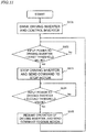
- FIG. 11 is a flowchart showing an exemplary flow of control since, after power transmission is begun, the emergency stop switch 400 is pressed to stop powering for the motor 31, until powering is restored.
- the power transmission control circuit 15 drives the driving inverter 13 and the control inverter 14 to begin power transmission. Thereafter, while monitoring the input power to the driving inverter 13, the power transmission control circuit 15 controls the control inverter 14.
- the power transmission control circuit 15 determines that an emergency stop by the switch 400 has been made.
- the power transmission control circuit 15 stops the driving inverter 13, and causes the communication circuit 16 to send a signal representing a command to stop the motor.
- This signal is transmitted to the motor control circuit 35 via the communication circuit 26.
- the motor control circuit 35 stops control of the motor inverter 33.
- the power transmission control circuit 15 While supply of power to the motor 31 is stopped, the power transmission control circuit 15 still keeps monitoring the input voltage to the driving inverter 13. Moreover, the motor control circuit 35 had stored to the memory the operation status (e.g., rotary position and rotational speed) of the motor 31 existing immediately before the stop.
- the operation status e.g., rotary position and rotational speed
- the power transmission control circuit 15 determines that the emergency stop has been canceled. In that case, at step S105, the operation of the driving inverter 13 is resumed, and causes the communication circuit 16 to send a signal representing a command that the motor again needs to be driven. This signal is transmitted to the motor control circuit 35 via the communication circuit 26. In response to this signal, the motor control circuit 35 resumes control of the motor inverter 33.
- the wireless power transmission system according to the present embodiment includes a plurality of wireless power feeding units that are connected in series.
- only one wireless power feeding unit 100 is provided between the power source 200 and the terminal load device 300.
- two or more wireless power feeding units are provided between the power source and the terminal load device.
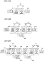
- FIGS. 12A through 12C are schematic diagrams showing different constructions for the wireless power transmission system according to the present disclosure.
- FIG. 12A shows a wireless power transmission system which includes one wireless power feeding unit 100, similarly to Embodiment 1.
- FIG. 12B shows a wireless power transmission system in which two wireless power feeding units 100A and 100B are provided between a power source 200 and a terminal load device 300B. In this example, after a power receiving module 20A in the first wireless power feeding unit 100A, a load device 300A and a power transmitting module 10B in the second wireless power feeding unit 100B are connected.
- FIG. 12C shows a wireless power transmission system in which a multitude of wireless power feeding units 100A through 100X are provided between a power source 200 and a terminal load device 300X.
- FIG. 13 is a block diagram showing an exemplary construction of a wireless power transmission system including two wireless power feeding units 100A and 100B.
- Each wireless power feeding unit 100A, 100B has the same construction as that of the wireless power feeding unit 100 of Embodiment 1.
- This wireless power transmission system includes a first actuator (load device) 300A that is connected to the first wireless power feeding unit 100A and a second actuator (load device) 300B that is connected to the second wireless power feeding unit 100B .
- the first actuator 300A is connected to a power receiving module 20A in the first wireless power feeding unit 100A.
- the second actuator 300B is connected to a power receiving module 20B in the second wireless power feeding unit 100B .
- the driving rectifier 23 in the first wireless power feeding unit 100A is connected to the driving inverter 13 in the second wireless power feeding unit 100B and the motor inverter 33 in the first actuator 300A.
- the control rectifier 24 in the first wireless power feeding unit 100A is connected to the control inverter 14 in the second wireless power feeding unit 100B and the motor control circuit 35 in the first actuator 300A. Therefore, even if the emergency stop switch 400 is turned OFF, supply of power to each control inverter 14 and each motor control circuit 35 is maintained. As a result, upon restoration, operation of the actuators 300A and 300B can be swiftly resumed.
- control inverter 14, power transmission control circuit 15, and communication circuit 16 in the second power transmitting module 10B are connected to the control rectifier 24 in the first power receiving module 20A; however, these may alternatively be connected to the driving rectifier 23.
- the switch 400 when the switch 400 is turned OFF, supply of power to the control system in the second wireless power feeding unit 100B and the second actuator 300B is stopped.
- supply of power to the control system in the first actuator 300A is maintained, and therefore, although partially, effects of the present disclosure will be obtained.
- the two wireless power feeding units 100A and 100B may together be regarded as one power feeding unit. Stated otherwise, a wireless power feeding unit may be constructed which includes a plurality of pairs each including a power transmitting module and a power receiving module. A similar construction to that shown in FIG. 13 is also applicable to the multi-unit construction shown in FIG. 12C .
- the communication circuit 16 in the power transmitting module 10 and the driving rectifier (first rectifier circuit) 23, the control rectifier (second rectifier circuit) 24, the power reception control circuit 25, and the communication circuit 26 in the power receiving module 20 are not essential constituent elements. Such constituent elements may be provided only as necessary.
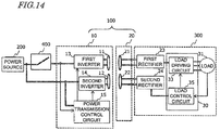
- FIG. 14 is a block diagram showing the construction of a wireless power transmission system according to another embodiment of the present disclosure.
- the power transmitting module 10 in the wireless power feeding unit 100 lacks the communication circuit 16
- the power receiving module 20 lacks the first rectifier circuit 23, the second rectifier circuit 24, the power reception control circuit 25, and the communication circuit 26.
- the load devices 300 includes the first rectifier circuit 23 connected to the first reception coil 21 and the second rectifier circuit 24 connected to the second reception coil 22. Such a construction can also attain the aforementioned effects.
- a matrix converter or the like which universally converts a single-phase current into a three-phase current may be used.
- Such a conversion circuit may be provided in either the power receiving module 20 or the actuator 300.
- the present disclosure encompasses wireless power transmission apparatuses as recited in the following Items.
- a wireless power feeding unit comprising:
- the wireless power feeding unit of claim 2 wherein, after stopping control of the first inverter circuit, when detecting that supply of electric power to the first inverter circuit is begun again, the power transmission control circuit resumes control of the first inverter circuit.
- a wireless power transmission system comprising:
- a wireless power transmission system comprising:
- the technique according to the present disclosure is applicable to electrically operated apparatuses, such as robots used in a factory or the like.
Description
- The present disclosure relates to a wireless power feeding unit, a power transmitting module, a power receiving module, and a wireless power transmission system.
- Electrically operated apparatuses (e.g., robot hand apparatuses) which perform various operations by using an end effector(s) connected to the leading end(s) of one or more arms are being developed. Such electrically operated apparatuses are utilized in various kinds of work, such as carrying articles at a factory.
- Japanese Laid-Open Patent Publication No.
2015-104764 - On the other hand, in the recent years, wireless power transmission techniques for transmitting electric power in a wireless (contactless) manner have been being developed. For example, International Publication No.
2015/019478 and Japanese Laid-Open Patent Publication No.2014-180078 -
US 2014/0354073 discloses a wireless power transmission system with a separate transmission part for information controlling the load. -
US 2012/0146580 discloses a wireless power transmission system with a separate transmission part for load (battery) info fed back to the transmitter. The info is transferred using coils. - The present disclosure provides a novel wireless power transmission technique which improves the work efficiency in an electrically operated apparatus, e.g., a robot, that has a movable section(s).
- A wireless power feeding unit according to one implementation of the present disclosure includes a power transmitting module and a power receiving module. The power transmitting module includes: a first inverter circuit which is connected to a power source via a switch, and which converts supplied electric power into first AC power and outputs the first AC power; a first transmission coil which is connected to the first inverter circuit, and which sends out the first AC power; a second inverter circuit which is connected to the power source or another power source not via the switch, and which converts supplied electric power into second AC power and outputs the second AC power; a second transmission coil which is connected to the second inverter circuit, and which sends out the second AC power; and a power transmission control circuit which is connected to the power source or another power source not via the switch, and which controls the first and second inverter circuits. The power receiving module includes: a first reception coil which is opposed to the first transmission coil, and which receives at least a portion of the first AC power; and a second reception coil which is opposed to the second transmission coil, and which receives at least a portion of the second AC power. At least a portion of the AC power received by the first reception coil is supplied to a load. At least a portion of the AC power received by the second reception coil is supplied to a load control circuit which controls the load. During operation of the first and second inverter circuits, even if the switch is turned OFF to stop supply of power to the first inverter circuit, the power transmission control circuit maintains control of the second inverter circuit.
- These general and specific aspects may be implemented using a system, a method, an integrated circuit, a computer program, or a storage medium, or any combination of a system, an apparatus, a method, an integrated circuit, a computer program, and/or a storage medium.
- According to one implementation of the present disclosure, the work efficiency in an apparatus that has a movable section(s), e.g., a robot, can be improved.
- Other features, elements, processes, steps, characteristics and advantages of the present invention will become more apparent from the following detailed description of preferred embodiments of the present invention with reference to the attached drawings.
-
-
FIG. 1 is a diagram schematically showing an example of a robot arm apparatus having a plurality of movable sections (e.g., joints). -
FIG. 2 is a diagram schematically showing a conventional construction in which power is supplied via cables. -
FIG. 3 is a diagram showing a specific example of the conventional construction shown inFIG. 2 . -
FIG. 4 is a diagram showing an exemplary construction of a robot in which power transmission in each joint is achieved wirelessly. -
FIG. 5 is a diagram showing an example of a robot arm apparatus in which wireless power transmission is applied. -
FIG. 6 is a block diagram showing the construction of a wireless power transmission system according toillustrative Embodiment 1 of the present disclosure. -
FIG. 7A is a diagram showing an exemplary equivalent circuit fortransmission coils reception coils power feeding unit 100. -
FIG. 7B is a diagram showing another exemplary equivalent circuit fortransmission coils reception coils power feeding unit 100. -
FIG. 8A is a diagram showing exemplary relative positions oftransmission coils reception coils -
FIG. 8B is a diagram showing another exemplary construction for thetransmission coils reception coils -
FIG. 8C is a diagram showing still another exemplary construction for thetransmission coils reception coils -
FIG. 8D is a diagram showing an exemplary shield plate. -
FIG. 8E is a diagram showing another exemplary shield plate. -
FIG. 9 is a perspective view showing another exemplary arrangement ofcoils -
FIG. 10A is a diagram showing an exemplary construction of a full-bridge type inverter circuit. -
FIG. 10B is a diagram showing an exemplary construction of a half-bridge type inverter circuit. -
FIG. 11 is a flowchart showing an exemplary flow of control since, after power transmission is begun, anemergency stop switch 400 is pressed to stop powering for themotor 31, until powering is restored. -
FIG. 12A is a diagram showing a wireless power transmission system which includes one wirelesspower feeding unit 100. -
FIG. 12B is a diagram showing a wireless power transmission system in which two wirelesspower feeding units power source 200 and aterminal load device 300B. -
FIG. 12C is a diagram showing a wireless power transmission system in which a multitude of wirelesspower feeding units 100A through 100X are provided between apower source 200 and aterminal load device 300X. -
FIG. 13 is a block diagram showing an exemplary construction of a wireless power transmission system including two wirelesspower feeding units -
FIG. 14 is a block diagram showing the construction of a wireless power transmission system according to another embodiment of the present disclosure. - Prior to describing embodiments of the present disclosure, findings providing the basis of the present disclosure will be described.
-
FIG. 1 is a diagram schematically showing an example of a robot arm apparatus having a plurality of movable sections (e.g., joints). Each movable section is constructed so as to be capable of rotation or expansion/contraction by means of an actuator that includes an electric motor (which hereinafter may simply be referred to as a "motor"). In order to control such an apparatus, it is necessary to individually supply electric power to the plurality of motors and control them. Supply of power from a power source to the plurality of motors has conventionally been achieved via a multitude of cables. -
FIG. 2 is a diagram schematically showing such a conventional construction. In the construction shown inFIG. 2 , electric power is supplied from a power source to a plurality of motors via wired bus connections. Each motor is controlled by a control device (controller) not shown. -
FIG. 3 is a diagram showing a specific example of the conventional construction shown inFIG. 2 . A robot in this example has two joints. Each joint is driven by a servo motor M. Each servo motor M is driven with a three-phase current. A controller includes as manymotor driving circuits 900 as there are motors M to be controlled. Eachmotor driving circuit 900 includes a converter, a three phase inverter, and a control circuit. The converter converts alternating current (AC) power from a power source into direct current (DC) power. The three phase inverter converts the DC power which is output from the converter into a three-phase AC power, and supplies it to the motor M. The control circuit controls the three phase inverter to supply necessary power to the motor M. Themotor driving circuit 900 obtains information concerning rotary position and rotational speed from the motor M, and adjusts the voltage of each phase based on this information. Such construction allows the operation of each joint to be controlled. - However, in this construction, as many cables as there are motors need to be provided. This causes accidents due to snagging of cables, which leads to the problems of limited ranges of motion and difficulty in changing parts. Moreover, repetitive bending of cables may deteriorate the cables, or even disrupt them. Therefore, the inventors have sought to reduce the cables in a movable section by applying a wireless power transmission technique.
-
FIG. 4 is a diagram showing an exemplary robot in which power transmission in each joint is achieved wirelessly. In this example, a three phase inverter and a control circuit to drive each motor M are provided within the robot, rather than in an external controller. In each joint, wireless power transmission is performed by utilizing magnetic field coupling between a transmission coil and a reception coil. In each joint, this robot includes a wirelesspower feeding unit 600 and anelectromechanical motor 700. Eachelectromechanical motor 700 includes a motor M, a three phase inverter, and a control circuit. Each wirelesspower feeding unit 600 includes a power transmitting circuit (also referred to as a "power transmitter"), a transmission coil, a reception coil, and a power receiving circuit (also referred to as a "power receiver"). The power transmitting circuit includes an inverter circuit. The power receiving circuit includes a rectifier circuit. The power transmitting circuit in the left wirelesspower feeding unit 600 shown inFIG. 4 , which is connected between a power source and the transmission coil, converts the supplied DC power into AC power, and supplies it to the transmission coil. The power receiving circuit converts the AC power which the reception coil has received from the transmission coil into DC power, and outputs it. The DC power which has been output from the power receiving circuit is supplied not only to theelectromechanical motor 700, but also the power transmitting circuit in the wirelesspower feeding unit 600 in any other joint. In this manner, electric power is also supplied to theelectromechanical motors 700 driving the other joints. -
FIG. 5 is a diagram showing an example of a robot arm apparatus in which the above-described wireless power transmission is applied. This robot arm apparatus has joints J1 to J6. Among these, the above-described wireless power transmission is applied to the joints J2 and J4. On the other hand, conventional wired power transmission is applied to the joints J1, J3, J5, and J6. The robot arm apparatus includes: a plurality of motors M1 to M6 which respectively drive the joints J1 to J6; motor control circuits Ctr3 to Ctr6 which respectively control the motors M3 to M6 among the motors M1 to M6; and two wireless power feeding units (intelligent robot harness units; also referred to as IHUs) IHU2 and IHU4 which are respectively provided in the joints J2 and J4. Motor control circuits Ctr1 and Ctr2 which respectively drive the motors M1 and M2 are provided in acontrol device 500 which is external to the robot. - The
control device 500 supplies electric power to the motors M1 and M2 and the wireless power feeding unit IHU2 in a wired manner. At the joint J2, the wireless power feeding unit IHU2 wirelessly transmits electric power via a pair of coils. The transmitted electric power is then supplied to the motors M3 and M4, the control circuits Ctr3 and Ctr4, and the wireless power feeding unit IHU4. The wireless power feeding unit IHU4 also wirelessly transmits electric power via a pair of coils in the joint J4. The transmitted electric power is supplied to the motors M5 and M6 and the control circuits Ctr5 and Ctr6. With such construction, cables for power transmission can be eliminated in the joints J2 and J4. - Now, for safety reasons, such an industrial robot as is shown in
FIG. 5 needs to have a switch for emergency stop. More specifically, there are standards stipulating that a switch for making an emergency stop (a push button) needs to be provided, such that the switch has a direct opening mechanism. A direct opening mechanism is a structure where a normally-closed (NC) contact is opened with the force by which a button is pressed, thereby cutting a current flow. In order to comply with this requirement under the safety standards, the example shown inFIG. 5 includes aswitch 400 for emergency stop being provided between thecontrol device 500 and the robot, the switch having a direct opening mechanism. By pressing the switch 400 (i.e., OFF), supply of power to each motor of the robot is forcedly cut, whereby the robot can be safely stopped. - However, turning the
switch 400 OFF to cut power to the robot stops not only supply of power to the motors M1 to M6, but also supply of power to the control circuits Ctr3 to Ctr6. As a result, when powering is begun again, initial operations associated with reboot of the respective control circuits must be performed again, thus resulting in the problem that a long time is required until operation can be resumed. A consequent operation resulting from this may be, for example: each arm section and hand (end effector) of the robot is forcedly returned to its initial position before operation can begin again. Such an operation makes it difficult to promptly begin work again from where the robot stopped, thus inducing deteriorations in work efficiency. - These problems are not confined to motor-driven apparatuses, but may similarly occur in any device that includes a load and a control circuit to control the load, such that the load operates with electric power.
- The inventors have found the aforementioned problems, and sought for constructions for solving these problems. The inventors have arrived at a novel construction, thereby accomplishing the technique according to the present disclosure, which, even after supply of power to a load such as a motor is stopped with an emergency stop switch, maintains supply of power to a load control circuit that controls the load. Hereinafter, the technique according to the present disclosure will be described in outline.
- A wireless power feeding unit according to one implementation of the present disclosure includes:
- a power transmitting module; and
- a power receiving module,
- the power transmitting module including
- a first inverter circuit which is connected to a power source via a switch, and which converts supplied electric power into first AC power and outputs the first AC power,
- a first transmission coil which is connected to the first inverter circuit, and which sends out the first AC power,
- a second inverter circuit which is connected to the power source or another power source not via the switch, and which converts supplied electric power into second AC power and outputs the second AC power,
- a second transmission coil which is connected to the second inverter circuit, and which sends out the second AC power, and
- a power transmission control circuit which is connected to the power source or another power source not via the switch, and which controls the first and second inverter circuits,
- the power receiving module including
- a first reception coil which is opposed to the first transmission coil, and which receives at least a portion of the first AC power, and
- a second reception coil which is opposed to the second transmission coil, and which receives at least a portion of the second AC power, wherein,
- at least a portion of the AC power received by the first reception coil is supplied to a load;
- at least a portion of the AC power received by the second reception coil is supplied to a load control circuit which controls the load; and
- during operation of the first and second inverter circuits, even if the switch is turned OFF to stop supply of power to the first inverter circuit, the power transmission control circuit maintains control of the second inverter circuit.
- In accordance with the above construction, the first inverter circuit which generates electric power to be supplied to the load (which may hereinafter be referred to as "power for driving purposes" or "drive power") is connected to the power source via the switch. On the other hand, the second inverter circuit which generates electric power to be supplied to the load control circuit (which may hereinafter be referred to as "power for control purposes" or "control power") and the power transmission control circuit are connected to the power source or another power source not via the switch. As a result, even if the switch is turned OFF so that power transmission by the first inverter circuit is stopped, power transmission by the second inverter circuit is continued, so that supply of power to the load control circuit can be maintained. As a result, when the switch is turned ON to restore supply of power to the motor, the motor operation can be promptly resumed.
- In the present specification, a "load" means any device that may operate with electric power. Examples of "loads" include devices such as motors, cameras (imaging devices), light sources, secondary batteries, and electronic circuits (e.g., power conversion circuits or microcontrollers). A device which includes a load and a circuit to control the load may be referred to as a "load device".
- Hereinafter, more specific embodiments of the present disclosure will be described. Note however that unnecessarily detailed descriptions may be omitted. For example, detailed descriptions on what is well known in the art or redundant descriptions on what is substantially the same construction may be omitted. This is to avoid lengthy description, and facilitate the understanding of those skilled in the art. The accompanying drawings and the following description, which are provided by the present inventors so that those skilled in the art can sufficiently understand the present disclosure, are not intended to limit the scope of claims. In the following description, identical or similar constituent elements are denoted by identical reference numerals.
-
FIG. 6 is a block diagram showing the construction of a wireless power transmission system according toillustrative Embodiment 1 of the present disclosure. For example, this wireless power transmission system may be adopted in an electric machine, such as a robot arm apparatus used to carry articles in a factory. The wireless power transmission system according to the present embodiment includes a wirelesspower feeding unit 100, apower source 200 which is connected to the wirelesspower feeding unit 100, anemergency stop switch 400, an actuator (as one example of a load device) 300, and a controller (control device) 500. Note that at least one of thepower source 200, theswitch 400, thecontroller 500, and theactuator 300 may be an external element to the wireless power transmission system. InFIG. 6 , thick lines indicate supply lines of electric power, whereas arrows indicate supply lines of signals. - The wireless
power feeding unit 100 includes apower transmitting module 10 and apower receiving module 20. Thepower transmitting module 10 includes a first inverter circuit (also referred to as a "driving inverter") 13, afirst transmission coil 11, a second inverter circuit (also referred to as a "control inverter") 14, asecond transmission coil 12, a powertransmission control circuit 15, and afirst communication circuit 16. The drivinginverter 13, which is connected to thepower source 200 via theswitch 400, converts supplied electric power into first AC power and outputs it. Thefirst transmission coil 11, which is connected to the drivinginverter 13, sends out the first AC power. Thecontrol inverter 14, which is connected to thepower source 200 not via theswitch 400, converts supplied electric power into second AC power and outputs it. Thesecond transmission coil 12, which is connected to thecontrol inverter 14, sends out the second AC power. The powertransmission control circuit 15, which is connected to thepower source 200 not via theswitch 400, controls the drivinginverter 13, thecontrol inverter 14, and thefirst communication circuit 16. Thefirst communication circuit 16 is connected to thepower source 200 not via theswitch 400. Thefirst communication circuit 16 sends a signal for controlling the motor 31 (as one example of a load) in theactuator 300. The signal for controlling themotor 31 may be a signal representing a command value of e.g. rotational speed of themotor 31, for example. The signal is supplied from theexternal controller 500 to thepower transmitting module 10. - The
power receiving module 20 includes afirst reception coil 21, a first rectifier circuit (also referred to as a "driving rectifier") 23, asecond reception coil 22, a second rectifier circuit (also referred to as a "control rectifier") 24, a powerreception control circuit 25, and asecond communication circuit 26. Thefirst reception coil 21 is opposed to thefirst transmission coil 11. Thefirst reception coil 21 receives at least a portion of the first AC power which is sent out from thefirst transmission coil 11. The drivingrectifier 23, which is connected to thefirst reception coil 21, converts the AC power received by thefirst reception coil 21 into first DC power and outputs it. Thesecond reception coil 22 is opposed to thesecond transmission coil 12. Thesecond reception coil 22 receives at least a portion of the second AC power which has been transmitted from thesecond transmission coil 12. Thecontrol rectifier 24, which is connected to thesecond reception coil 22, converts the AC power received by thesecond reception coil 22 into second DC power and outputs it. The powerreception control circuit 25 is driven by the second DC power output from thecontrol rectifier 24, and controls thesecond communication circuit 26. Thesecond communication circuit 26 performs communications between thefirst communication circuit 16 on the power transmission side and themotor control circuit 35 in theactuator 300. Thesecond communication circuit 26 receives a signal which has been sent from thefirst communication circuit 16, and sends it to themotor control circuit 35. In response to a request from themotor control circuit 35, thesecond communication circuit 26 may send a signal with which to perform an operation of compensating for the load variation in themotor 31, for example, to thefirst communication circuit 16. Based on this signal, the powertransmission control circuit 15 can control the drivinginverter 13 to adjust drive power. As a result, for example, an always-constant voltage may be given to themotor inverter 33 in theactuator 300. - The
actuator 300 according to the present embodiment causes thepower receiving module 20 to move or rotate relative to thepower transmitting module 10. During this operation, thefirst transmission coil 11 and thefirst reception coil 21 maintain an opposed state, and thesecond transmission coil 12 and thesecond reception coil 22 also maintain an opposed state. Theactuator 300 includes aservo motor 31 which is driven by a three-phase current, and amotor amplifier 30 to drive themotor 31. Themotor amplifier 30 includes: a motor inverter (motor driving circuit) 33 which converts the DC power having been output from the drivingrectifier 23 into three-phase AC power, and supplies it to themotor 31; and amotor control circuit 35 which controls themotor inverter 33. During operation of themotor 31, themotor control circuit 35 detects information on rotary position and rotational speed by using e.g. a rotary encoder, and based on this information, controls themotor inverter 33 so as to realize a desired rotating operation. Note that themotor 31 may not be a motor which is driven with a three-phase current. In the case where themotor 33 is a DC-driven motor, a motor driving circuit which is suited for that motor construction is to be used instead of a three phase inverter. - At least a portion of the first DC power which is output from the driving
rectifier 23 is supplied to themotor inverter 33. At least a portion of the second DC power which is output from thecontrol rectifier 24 is supplied to themotor control circuit 35. Even if theswitch 400 is turned OFF during operation of the drivinginverter 13 and thecontrol inverter 14 so that supply of power to the drivinginverter 13 is stopped, the powertransmission control circuit 15 maintains control of thecontrol inverter 14. As a result, even after supply of power to themotor inverter 33 is stopped, supply of power to themotor control circuit 35 is maintained. Since themotor control circuit 35 stores the operation status existing at the time when themotor 31 stops, it is possible to swiftly resume the operation of theactuator 300 when theswitch 400 is turned ON again so that powering is begun again. - In order to realize the above operation, the power
transmission control circuit 15 performs power transmission control while monitoring the electric power which is supplied to the drivinginverter 13. By detecting a decrease in the electric power value that is being input to the drivinginverter 13, the powertransmission control circuit 15 detects that theemergency stop switch 400 has been pressed (i.e., theswitch 400 has been turned OFF). Upon detecting a decrease (or stop) of the supplied electric power, the powertransmission control circuit 15 stops control of the drivinginverter 13, while maintaining control of thecontrol inverter 14. In the meantime, the powertransmission control circuit 15 may instruct thecommunication circuit 16 to send a predetermined signal (e.g., a command to stop the motor) to themotor control circuit 35. Upon receiving this signal, themotor control circuit 35 can stop controlling themotor inverter 33. When electric power to the driving system is suspended, this prevents unnecessary inverter control from being continued. - Thus, in the present embodiment, electric power for motor control purposes is input independently of the electric power for motor driving purposes. Moreover, electric power for control and communication purposes in the wireless
power feeding unit 100 is input independently of the electric power for driving purposes. As a result, even when powering of themotor 31 in theactuator 300 is cut by theemergency stop switch 400, it is still possible to supply electric power to the control system and the communication system. Thus, safety is ensured while the drive power is suspended, and once emergency stop is canceled, it is possible to safely and swiftly resume the usual operation. - Next, the construction of the respective constituent elements in the present embodiment will be described in more detail.
-
FIG. 7A is a diagram showing an exemplary equivalent circuit for the transmission coils 11 and 12 and the reception coils 21 and 22 in the wirelesspower feeding unit 100. As shown in the figure, each coil functions as a resonant circuit having an inductance component and a capacitance component. By ensuring that the resonant frequencies of two coils opposing each other have close values, electric power can be transmitted with a high efficiency. Each transmission coil receives AC power supplied from an inverter circuit. Owing to a magnetic field that is generated with this AC power from the transmission coil, electric power is transmitted to the reception coil. In this example, the transmission coils 11 and 12 and the reception coils 21 and 22 both function as series resonant circuits. -
FIG. 7B is a diagram showing another exemplary equivalent circuit for the transmission coils 11 and 12 and the reception coils 21 and 22 in the wirelesspower feeding unit 100. In this example, the transmission coils 11 and 12 function as series resonant circuits, whereas the reception coils 21 and 22 function as parallel resonant circuits. In another possible implementation, the transmission coils 11 and 12 may constitute parallel resonant circuits. - Each coil may be, for example, a planar coil or a laminated coil that is formed on a circuit board, or a wound coil of a copper wire, a litz wire, a twisted wire, or the like. The capacitance component in each resonant circuit may be realized by the parasitic capacitance of the coil, or alternatively a capacitor of a chip shape or a lead shape may be additionally provided, for example.
- Typically, the resonant frequency f0 of the resonant circuit is set equal to the transmission frequency f that exists during power transmission. The resonant frequency f0 of each resonant circuit may not be exactly equal to the transmission frequency f. Each resonant frequency f0 may be set to a value in the range of about 50% to 150% of the transmission frequency f, for example. The frequency f of power transmission may be set to e.g. 50 Hz to 300 GHz, more preferably 20 kHz to 10 GHz, still more preferably 20 kHz to 20 MHz, and still more preferably 20 kHz to 7 MHz. Within any such frequency band, a frequency of drive power and a frequency of control power may be selected. The frequency of drive power and the frequency of control power may be set to different values.
-
FIG. 8A is a diagram showing exemplary relative positions of the transmission coils 11 and 12 and the reception coils 21 and 22. The structure in this example may be applied to a coil in a movable section that is capable of rotating, such as a joint of a robot. Although the reception coils 21 and 22 actually are opposed respectively to the transmission coils 11 and 12,FIG. 8A illustrates these coils as being side by side, for ease of understanding. In this example, the transmission coils 11 and 12 and the reception coils 21 and 22 are all planar coils of circular shape. The transmission coils 11 and 12 are disposed concentrically, such that thetransmission coil 12 fits inside thetransmission coil 11. Similarly, the reception coils 21 and 22 are disposed concentrically, such that thereception coil 22 fits inside thereception coil 21. Contrary to this example, thetransmission coil 11 may be disposed inside thetransmission coil 21, and thereception coil 21 may be disposed inside thereception coil 22. Each of the transmission coils 11 and 12 and the reception coils 21 and 22 in this example is covered with a magnetic substance. -
FIG. 8B is a diagram showing another exemplary construction for the transmission coils 11 and 12 and the reception coils 21 and 22. In the example ofFIG. 8B , an interspace (air gap) exists between the magnetic substance covering thetransmission coil 11 and the magnetic substance covering thetransmission coil 21, and between the magnetic substance covering thereception coil 21 and the magnetic substance covering thereception coil 22. It has been found that providing such air gaps suppresses electromagnetic interference between coils. -
FIG. 8C is a diagram showing still another exemplary construction for the transmission coils 11 and 12 and the reception coils 21 and 22. In the example ofFIG. 8C , a shield plate is further added to the construction shown inFIG. 8B . The shield plate shown in the figure is an electrically conductive member of annular shape which is disposed in the interspace between pieces of magnetic substance. It has been found that adding a shield plate inside an air gap allows for further suppression of electromagnetic interference between coils. - A shield plate may be annular, as shown in
FIG. 8D . A shield plate may be an annular shape with one or more slits in it, such as shown inFIG. 8E . By providing slits, an eddy current that is induced in the shield plate owing to a magnetic field that is generated by the coil can be suppressed. In other words, decrease in the Q value of the coil can be suppressed. - The material of a shield plate may be a metal such as copper or aluminum, for example. Otherwise, the following constructions may be employed as shield plates or alternatives thereof.
- a construction obtained by coating the side wall of an air gap between pieces of magnetic substance with an electrically conductive paint (e.g., a silver paint or a copper paint)
- a construction obtained by attaching an electrically conductive tape (e.g., a copper tape or an aluminum tape) on the side wall of an air gap between pieces of magnetic substance
- an electrically conductive plastic (i.e., a material including a metal filler kneaded in a plastic)
- Any of these may exhibit a similar function to that of the aforementioned shield plate. Such constructions will collectively be referred to as "shields". The shape of a shield is not limited to an annular shape as is shown in the figures. A shield may have a polygonal or elliptical shape, for example. A plurality of metal plates may be placed together to compose a shield.
- In the constructions of
FIG. 8B andFIG. 8C , Table 1 shows results of analyzing the width of the air gap between pieces of magnetic substance, the coupling coefficient (Ltxp-LRxp) between thetransmission coil 11 for driving purposes and thereception coil 11 for driving purposes, and the coupling coefficient (Ltxc-LRxp) between thetransmission coil 12 for control purposes and thereception coil 21 for driving purposes. Assuming that the gap between coils is 2 mm; eachcoil coil [Table 1] air gap size between magnetic substance pieces 0 mm 1 mm 2 mm coupling coefficients (without shield plates) Ltxp - LRxp 0.845 0.820 0.802 Ltxc - LRxp 0.250 0.163 0.105 coupling coefficients (with shield plates) Ltxp - LRxp - 0.778 0.776 Ltxc - LRxp - 0.013 0.006 - It can be seen from the results of Table 1 that increasing the air gap between pieces of magnetic substance reduces the coupling coefficient (Ltxc-Lrxp) between the
transmission coil 12 for control purposes and thereception coil 21 for driving purposes. Although the interference between thecoils transmission coil 12 for control purposes and thereception coil 21 for driving purposes, thereby further reducing the interference between them. Although not shown in Table 1, interference between thetransmission coil 11 for driving purposes and thereception coil 22 for control purposes can also be suppressed by introducing an increased air gap and providing shield plates. - One of the combination of transmission coils 11 and 12 and the combination of reception coils 21 and 22 may have a construction without an air gap between pieces of magnetic substance, such as shown in
FIG. 8A , and the other may have a construction with an air gap between pieces of magnetic substance, such as shown inFIG. 8B . Moreover, one of the combination of transmission coils 11 and 12 and the combination of reception coils 21 and 22 may have a construction with a shield plate in an air gap between pieces of magnetic substance, such as shown inFIG. 8C , and the other may have a construction without shield plates, such as shown inFIG. 8A and FIG. 8B . With such constructions, too, the effect of suppressing electromagnetic interference between coils is obtained. - The shapes and relative positions of the transmission coils 11 and 12 and the reception coils 21 and 22 are not limited to those exemplified in
FIGS. 8A and 8B , and they permit various structures. For example, in any site of a robot arm that undergoes linear motion (e.g., expansion or contraction), a coil of rectangular shape may be used. -
FIG. 9 is a perspective view showing another exemplary arrangement ofcoils coil transmission coil 11 is larger than thetransmission coil 12, and thereception coil 21 is larger than thereception coil 22. With this construction, even if the power receiving module moves relative to the power transmitting module, the coils will remain opposed. In the construction shown inFIG. 9 , thetransmission coil 11 may be smaller than thetransmission coil 12, and thereception coil 21 may be smaller than thereception coil 22. -
FIGS. 10A and 10B are diagrams showing exemplary constructions for eachinverter circuit FIG. 10A shows an exemplary construction of a full-bridge type inverter circuit. In this example, by controlling ON or OFF of the four switching elements S1 to S4 included in theinverter circuit transmission control circuit 15 converts input DC power into AC power having a desired frequency f and voltage V (effective values). In order to realize this control, the powertransmission control circuit 15 may include a gate driver circuit that supplies a control signal to each switching element.FIG. 10B shows an exemplary construction of a half-bridge type inverter circuit. In this example, by controlling ON or OFF of the two switching elements S1 and S2 included in theinverter circuit transmission control circuit 15 converts input DC power into AC power having a desired frequency f and voltage V (effective values). Theinverter circuit FIG. 10A or 10B . - The power
transmission control circuit 15, the powerreception control circuit 25, and themotor control circuit 35 can be implemented as circuits including a processor and a memory, e.g., microcontroller units (MCU). By executing a computer program which is stored in the memory, various controls can be performed. The powertransmission control circuit 15, the powerreception control circuit 25, and themotor control circuit 35 may be implemented in special-purpose hardware that is adapted to perform the operation according to the present embodiment. - The
communication circuits communication circuits - The
motor 31 may be a motor that is driven with a three-phase current, e.g., a permanent magnet synchronous motor or an induction motor, although this is not a limitation. Themotor 31 may any other type of motor, such as a DC motor. In that case, instead of the motor inverter 33 (which is a three-phase inverter circuit), a motor driving circuit which is suited for the structure of themotor 31 is to be used. - The
power source 200 may be any power source that outputs DC power. Thepower source 200 may be any power source, e.g., a mains supply, a primary battery, a secondary battery, a photovoltaic cell, a fuel cell, a USB (Universal Serial Bus) power source, a high-capacitance capacitor (e.g., an electric double layer capacitor), or a voltage converter that is connected to a mains supply, for example. AlthoughFIG. 6 illustrates an example where one common power source serves as the power source for the drivinginverter 13 and as the power source for thecontrol inverter 14, powertransmission control circuit 15, andcommunication circuit 16, these power sources may be discrete. - The
switch 400 is a switch for emergency stop, and has the aforementioned direct opening mechanism. However, this is not a limitation; the technique of the present disclosure is applicable also to other types of switches. Theswitch 400 selectively establishes conduction/non-conduction between thepower source 200 and the drivinginverter 13. - The
controller 500 is a control device which controls the operation each load that is included in the wireless power transmission system. Thecontroller 500 determines load command values (e.g., rotational speed and torque) that determine the operation status of themotor 31 of theactuator 300, and send them to thecommunication circuit 16. - Next, the operation of the power
transmission control circuit 15 according to the present embodiment will be described in more detail. -
FIG. 11 is a flowchart showing an exemplary flow of control since, after power transmission is begun, theemergency stop switch 400 is pressed to stop powering for themotor 31, until powering is restored. First, at step S101, the powertransmission control circuit 15 drives the drivinginverter 13 and thecontrol inverter 14 to begin power transmission. Thereafter, while monitoring the input power to the drivinginverter 13, the powertransmission control circuit 15 controls thecontrol inverter 14. At step S102, upon detecting that the input power to the drivinginverter 13 has become lower than a predetermined threshold value (first threshold value), the powertransmission control circuit 15 determines that an emergency stop by theswitch 400 has been made. In that case, at step S103, the powertransmission control circuit 15 stops the drivinginverter 13, and causes thecommunication circuit 16 to send a signal representing a command to stop the motor. This signal is transmitted to themotor control circuit 35 via thecommunication circuit 26. In response to this signal, themotor control circuit 35 stops control of themotor inverter 33. As a result, not only does electric power cease to be supplied to the drivinginverter 13 and themotor inverter 33, but control of the drivinginverter 13 and themotor inverter 33 also stops. - While supply of power to the
motor 31 is stopped, the powertransmission control circuit 15 still keeps monitoring the input voltage to the drivinginverter 13. Moreover, themotor control circuit 35 had stored to the memory the operation status (e.g., rotary position and rotational speed) of themotor 31 existing immediately before the stop. - Upon detecting at step S104 that the input power to the driving
inverter 13 has exceeded a second threshold value which is equal to or greater than the first threshold value, the powertransmission control circuit 15 determines that the emergency stop has been canceled. In that case, at step S105, the operation of the drivinginverter 13 is resumed, and causes thecommunication circuit 16 to send a signal representing a command that the motor again needs to be driven. This signal is transmitted to themotor control circuit 35 via thecommunication circuit 26. In response to this signal, themotor control circuit 35 resumes control of themotor inverter 33. - Through the above operation, even if the driving system has come to an emergency stop by virtue of the
switch 400, operation of the control system is continued, such that operation of theactuator 300 can be swiftly resumed once electric power to the driving system is restored. In the present embodiment, in particular, not only does electric power cease to be supplied to the drivinginverter 13 and themotor inverter 33 upon an emergency stop, but control of the drivinginverter 13 and themotor inverter 33 also stops, whereby the emergency stop can be made in a safer manner. - Next, a wireless power transmission system according to
Embodiment 2 will be described. The wireless power transmission system according to the present embodiment includes a plurality of wireless power feeding units that are connected in series. InEmbodiment 1, only one wirelesspower feeding unit 100 is provided between thepower source 200 and theterminal load device 300. On the other hand, in the present embodiment, two or more wireless power feeding units are provided between the power source and the terminal load device. -
FIGS. 12A through 12C are schematic diagrams showing different constructions for the wireless power transmission system according to the present disclosure.FIG. 12A shows a wireless power transmission system which includes one wirelesspower feeding unit 100, similarly toEmbodiment 1.FIG. 12B shows a wireless power transmission system in which two wirelesspower feeding units power source 200 and aterminal load device 300B. In this example, after apower receiving module 20A in the first wirelesspower feeding unit 100A, aload device 300A and apower transmitting module 10B in the second wirelesspower feeding unit 100B are connected.FIG. 12C shows a wireless power transmission system in which a multitude of wirelesspower feeding units 100A through 100X are provided between apower source 200 and aterminal load device 300X. By adopting the construction shown inFIG. 12B or 12C , it becomes possible to achieve wireless power transmission in a plurality of movable sections (e.g., joints or expandable sections) and supply power to a plurality of load devices, as has been described with reference to e.g.FIG. 5 . -
FIG. 13 is a block diagram showing an exemplary construction of a wireless power transmission system including two wirelesspower feeding units power feeding unit power feeding unit 100 ofEmbodiment 1. This wireless power transmission system includes a first actuator (load device) 300A that is connected to the first wirelesspower feeding unit 100A and a second actuator (load device) 300B that is connected to the second wirelesspower feeding unit 100B. Thefirst actuator 300A is connected to apower receiving module 20A in the first wirelesspower feeding unit 100A. Thesecond actuator 300B is connected to apower receiving module 20B in the second wirelesspower feeding unit 100B. - The driving
rectifier 23 in the first wirelesspower feeding unit 100A is connected to the drivinginverter 13 in the second wirelesspower feeding unit 100B and themotor inverter 33 in thefirst actuator 300A. On the other hand, thecontrol rectifier 24 in the first wirelesspower feeding unit 100A is connected to thecontrol inverter 14 in the second wirelesspower feeding unit 100B and themotor control circuit 35 in thefirst actuator 300A. Therefore, even if theemergency stop switch 400 is turned OFF, supply of power to eachcontrol inverter 14 and eachmotor control circuit 35 is maintained. As a result, upon restoration, operation of theactuators - In the construction of
FIG. 13 , thecontrol inverter 14, powertransmission control circuit 15, andcommunication circuit 16 in the secondpower transmitting module 10B are connected to thecontrol rectifier 24 in the firstpower receiving module 20A; however, these may alternatively be connected to the drivingrectifier 23. In such a construction, when theswitch 400 is turned OFF, supply of power to the control system in the second wirelesspower feeding unit 100B and thesecond actuator 300B is stopped. However, supply of power to the control system in thefirst actuator 300A is maintained, and therefore, although partially, effects of the present disclosure will be obtained. - In the construction of
FIG. 13 , the two wirelesspower feeding units FIG. 13 is also applicable to the multi-unit construction shown inFIG. 12C . - In the wireless
power feeding unit 100 according to the present disclosure, thecommunication circuit 16 in thepower transmitting module 10 and the driving rectifier (first rectifier circuit) 23, the control rectifier (second rectifier circuit) 24, the powerreception control circuit 25, and thecommunication circuit 26 in thepower receiving module 20 are not essential constituent elements. Such constituent elements may be provided only as necessary. -
FIG. 14 is a block diagram showing the construction of a wireless power transmission system according to another embodiment of the present disclosure. In this wireless power transmission system, thepower transmitting module 10 in the wirelesspower feeding unit 100 lacks thecommunication circuit 16, whereas thepower receiving module 20 lacks thefirst rectifier circuit 23, thesecond rectifier circuit 24, the powerreception control circuit 25, and thecommunication circuit 26. On the other hand, theload devices 300 includes thefirst rectifier circuit 23 connected to thefirst reception coil 21 and thesecond rectifier circuit 24 connected to thesecond reception coil 22. Such a construction can also attain the aforementioned effects. - Instead of the
rectifiers FIG. 14 , other types of conversion circuits may also be used. For example, a matrix converter or the like which universally converts a single-phase current into a three-phase current may be used. Such a conversion circuit may be provided in either thepower receiving module 20 or theactuator 300. - As described above, the present disclosure encompasses wireless power transmission apparatuses as recited in the following Items.
- A wireless power feeding unit comprising:
- a power transmitting module; and
- a power receiving module,
- the power transmitting module including
- a first inverter circuit which is connected to a power source via a switch, and which converts supplied electric power into first AC power and outputs the first AC power,
- a first transmission coil which is connected to the first inverter circuit, and which sends out the first AC power,
- a second inverter circuit which is connected to the power source or another power source not via the switch, and which converts supplied electric power into second AC power and outputs the second AC power,
- a second transmission coil which is connected to the second inverter circuit, and which sends out the second AC power, and
- a power transmission control circuit which is connected to the power source or another power source not via the switch, and which controls the first and second inverter circuits,
- the power receiving module including
- a first reception coil which is opposed to the first transmission coil, and which receives at least a portion of the first AC power, and
- a second reception coil which is opposed to the second transmission coil, and which receives at least a portion of the second AC power, wherein,
- at least a portion of the AC power received by the first reception coil is supplied to a load;
- at least a portion of the AC power received by the second reception coil is supplied to a load control circuit which controls the load; and
- during operation of the first and second inverter circuits, even if the switch is turned OFF to stop supply of power to the first inverter circuit, the power transmission control circuit maintains control of the second inverter circuit.
- The wireless power feeding unit of
claim 1, wherein the power transmission control circuit monitors electric power which is supplied to the first inverter circuit, and when detecting that supply of electric power has stopped, stops control of the first inverter circuit while maintaining control of the second inverter circuit. - The wireless power feeding unit of
claim 2, wherein, after stopping control of the first inverter circuit, when detecting that supply of electric power to the first inverter circuit is begun again, the power transmission control circuit resumes control of the first inverter circuit. - The wireless power feeding unit of any of
claims 1 to 3, wherein, - the power transmitting module further includes a first communication circuit which sends a signal for controlling the load;
- the power receiving module further includes a second communication circuit which receives the signal having been sent from the first communication circuit and sends the signal to the load control circuit;
- the first and second communication circuits are connected to the power source or another power source not via the switch; and
- the power transmission control circuit monitors electric power which is supplied to the first inverter circuit, and when detecting that supply of the electric power has stopped, causes the first communication circuit to send a signal for stopping the load, while maintaining control of the second inverter circuit.
- The wireless power feeding unit of
claim 4, wherein after causing the first communication circuit to send a signal for stopping the load, when detecting that supply of electric power to the first inverter circuit is begun again, the power transmission control circuit causes the first communication circuit to send a signal for resuming operation of the load. - The wireless power feeding unit of any of
claims 1 to 5, wherein, - the first and second transmission coils are planar coils, one of the first and second transmission coils being disposed inside the other of the first and second transmission coils; and
- the first and second reception coils are planar coils, one of the first and second reception coils being disposed inside the other of the first and second reception coils.
- The wireless power feeding unit of claim 6, wherein,
- each of the first and second reception coils is covered by a magnetic substance; and
- an interspace exists between the magnetic substance covering the first reception coil and the magnetic substance covering the second reception coil.
- The wireless power feeding unit of any of
claims 1 to 7, wherein, - the power receiving module further includes
- a first rectifier circuit which is connected to the first reception coil, and which converts AC power received by the first reception coil into first DC power and outputs the first DC power, and
- a second rectifier circuit which is connected to the second reception coil, and which converts AC power received by the second reception coil into second DC power and outputs the second DC power;
- at least a portion of the first DC power which is output from the first rectifier circuit is supplied to the load; and
- at least a portion of the second DC power which is output from the second rectifier circuit is supplied to the load control circuit.
- The wireless power feeding unit of claim 8, further comprising:
- a second power transmitting module; and
- a second power receiving module,
- the second power transmitting module including
- a third inverter circuit which is connected to the first rectifier circuit, and which converts the first DC power into third AC power and outputs the third AC power,
- a third transmission coil which is connected to the third inverter circuit, and which sends out the third AC power,
- a fourth inverter circuit which is connected to the first rectifier circuit or the second rectifier circuit, and which converts the first DC power or the second DC power into fourth AC power and outputs the fourth AC power,
- a fourth transmission coil which is connected to the fourth inverter circuit, and which sends out the fourth AC power, and
- a second power transmission control circuit which controls the third inverter circuit and the fourth inverter circuit,
- the second power receiving module including
- a third reception coil which is opposed to the third transmission coil, and which receives at least a portion of the third AC power, and
- a fourth reception coil which is opposed to the fourth transmission coil, and which receives at least a portion of the fourth AC power, wherein,
- at least a portion of the AC power received by the third reception coil is supplied to a further load control circuit which controls a further load; and
- at least a portion of the AC power received by the fourth reception coil is supplied to the further load control circuit which controls the further load.
- The wireless power feeding unit of any of
claims 1 to 9, wherein the load comprises an electric motor. - A wireless power transmission system comprising:
- the wireless power feeding unit of any of
claims 1 to 10; and - an apparatus including the load and the load control circuit.
- The wireless power transmission system of
claim 11, wherein, - the load comprises an electric motor;
- the apparatus is an actuator further including a motor driving circuit which drives the electric motor;
- the load control circuit is a motor control circuit which controls the motor driving circuit; and
- the actuator causes the power receiving module to move or rotate relative to the power transmitting module while maintaining a state where the first transmission coil and the first reception coil are opposed and the second transmission coil and the second reception coil are opposed.
- A wireless power transmission system comprising:
- the wireless power feeding unit of any of
claims 1 to 10; and - the switch.
- The wireless power transmission system of
claim 13, wherein the switch comprises a direct opening mechanism. - The power transmitting module in the wireless power feeding unit of any of
claims 1 to 10. - The power receiving module in the wireless power feeding unit of any of
claims 1 to 10. - The technique according to the present disclosure is applicable to electrically operated apparatuses, such as robots used in a factory or the like.
- While the present invention has been described with respect to preferred embodiments thereof, it will be apparent to those skilled in the art that the disclosed invention may be modified in numerous ways and may assume many embodiments other than those specifically described above. Accordingly, it is intended by the appended claims to cover all modifications of the invention that fall within the true spirit and scope of the invention.
- This application is based on Japanese Patent Applications No.
2016-232180
Claims (16)
- A wireless power feeding unit (100) comprising:a power transmitting module (10); anda power receiving module (20),the power transmitting module includinga first inverter circuit (13) which is connected to a power source (200) via a switch (400), and which converts supplied electric power into first AC power and outputs the first AC power,a first transmission coil (11) which is connected to the first inverter circuit (13), and which sends out the first AC power,a second inverter circuit (14) which is connected to the power source (200) or another power source not via the switch (400), and which converts supplied electric power into second AC power and outputs the second AC power,a second transmission coil (12) which is connected to the second inverter circuit (14), and which sends out the second AC power, anda power transmission control circuit (15) which is connected to the power source or another power source not via the switch (400), and which controls the first and second inverter circuits,the power receiving module includinga first reception coil (21) which is opposed to the first transmission coil (11), and which receives at least a portion of the first AC power, anda second reception coil (22) which is opposed to the second transmission coil (12), and which receives at least a portion of the second AC power, wherein,at least a portion of the AC power received by the first reception coil is supplied to a load;at least a portion of the AC power received by the second reception coil is supplied to a load control circuit which controls the load; andduring operation of the first and second inverter circuits, even if the switch is turned OFF to stop supply of power to the first inverter circuit, the power transmission control circuit maintains control of the second inverter circuit.
- The wireless power feeding unit of claim 1, wherein the power transmission control circuit monitors electric power which is supplied to the first inverter circuit, and when detecting that supply of electric power has stopped, stops control of the first inverter circuit while maintaining control of the second inverter circuit.
- The wireless power feeding unit of claim 2, wherein, after stopping control of the first inverter circuit, when detecting that supply of electric power to the first inverter circuit is begun again, the power transmission control circuit resumes control of the first inverter circuit.
- The wireless power feeding unit of any of claims 1 to 3, wherein,the power transmitting module further includes a first communication circuit which sends a signal for controlling the load;the power receiving module further includes a second communication circuit which receives the signal having been sent from the first communication circuit and sends the signal to the load control circuit;the first and second communication circuits are connected to the power source or another power source not via the switch; andthe power transmission control circuit monitors electric power which is supplied to the first inverter circuit, and when detecting that supply of the electric power has stopped, causes the first communication circuit to send a signal for stopping the load, while maintaining control of the second inverter circuit.
- The wireless power feeding unit of claim 4, wherein after causing the first communication circuit to send a signal for stopping the load, when detecting that supply of electric power to the first inverter circuit is begun again, the power transmission control circuit causes the first communication circuit to send a signal for resuming operation of the load.
- The wireless power feeding unit of any of claims 1 to 5, wherein,the first and second transmission coils are planar coils, one of the first and second transmission coils being disposed inside the other of the first and second transmission coils; andthe first and second reception coils are planar coils, one of the first and second reception coils being disposed inside the other of the first and second reception coils.
- The wireless power feeding unit of claim 6, wherein,each of the first and second reception coils is covered by a magnetic substance; andan interspace exists between the magnetic substance covering the first reception coil and the magnetic substance covering the second reception coil.
- The wireless power feeding unit of any of claims 1 to 7, wherein,the power receiving module further includesa first rectifier circuit which is connected to the first reception coil, and which converts AC power received by the first reception coil into first DC power and outputs the first DC power, anda second rectifier circuit which is connected to the second reception coil, and which converts AC power received by the second reception coil into second DC power and outputs the second DC power;at least a portion of the first DC power which is output from the first rectifier circuit is supplied to the load; andat least a portion of the second DC power which is output from the second rectifier circuit is supplied to the load control circuit.
- The wireless power feeding unit of claim 8, further comprising:a second power transmitting module; anda second power receiving module,the second power transmitting module includinga third inverter circuit which is connected to the first rectifier circuit, and which converts the first DC power into third AC power and outputs the third AC power,a third transmission coil which is connected to the third inverter circuit, and which sends out the third AC power,a fourth inverter circuit which is connected to the first rectifier circuit or the second rectifier circuit, and which converts the first DC power or the second DC power into fourth AC power and outputs the fourth AC power,a fourth transmission coil which is connected to the fourth inverter circuit, and which sends out the fourth AC power, anda second power transmission control circuit which controls the third inverter circuit and the fourth inverter circuit,the second power receiving module includinga third reception coil which is opposed to the third transmission coil, and which receives at least a portion of the third AC power, anda fourth reception coil which is opposed to the fourth transmission coil, and which receives at least a portion of the fourth AC power, wherein,at least a portion of the AC power received by the third reception coil is supplied to a further load control circuit which controls a further load; andat least a portion of the AC power received by the fourth reception coil is supplied to the further load control circuit which controls the further load.
- The wireless power feeding unit of any of claims 1 to 9, wherein the load comprises an electric motor.
- A wireless power transmission system comprising:the wireless power feeding unit of any of claims 1 to 10; andan apparatus including the load and the load control circuit.
- The wireless power transmission system of claim 11, wherein,the load comprises an electric motor;the apparatus is an actuator further including a motor driving circuit which drives the electric motor;the load control circuit is a motor control circuit which controls the motor driving circuit; andthe actuator causes the power receiving module to move or rotate relative to the power transmitting module while maintaining a state where the first transmission coil and the first reception coil are opposed and the second transmission coil and the second reception coil are opposed.
- A wireless power transmission system comprising:the wireless power feeding unit of any of claims 1 to 10; andthe switch.
- The wireless power transmission system of claim 13, wherein the switch comprises a direct opening mechanism.
- The power transmitting module in the wireless power feeding unit of any of claims 1 to 10.
- The power receiving module in the wireless power feeding unit of any of claims 1 to 10.
Priority Applications (1)
| Application Number | Priority Date | Filing Date | Title |
|---|---|---|---|
| EP19150474.5A EP3493362A1 (en) | 2016-11-30 | 2017-11-29 | Wireless power feeding unit, power transmitting module, power receiving module, and wireless power transmission system |
Applications Claiming Priority (1)
| Application Number | Priority Date | Filing Date | Title |
|---|---|---|---|
| JP2016232180 | 2016-11-30 |
Related Child Applications (2)
| Application Number | Title | Priority Date | Filing Date |
|---|---|---|---|
| EP19150474.5A Division EP3493362A1 (en) | 2016-11-30 | 2017-11-29 | Wireless power feeding unit, power transmitting module, power receiving module, and wireless power transmission system |
| EP19150474.5A Division-Into EP3493362A1 (en) | 2016-11-30 | 2017-11-29 | Wireless power feeding unit, power transmitting module, power receiving module, and wireless power transmission system |
Publications (2)
| Publication Number | Publication Date |
|---|---|
| EP3331128A1 EP3331128A1 (en) | 2018-06-06 |
| EP3331128B1 true EP3331128B1 (en) | 2019-03-13 |
Family
ID=60543384
Family Applications (2)
| Application Number | Title | Priority Date | Filing Date |
|---|---|---|---|
| EP17204419.0A Active EP3331128B1 (en) | 2016-11-30 | 2017-11-29 | Wireless power feeding unit, power transmitting module, power receiving module, and wireless power transmission system |
| EP19150474.5A Withdrawn EP3493362A1 (en) | 2016-11-30 | 2017-11-29 | Wireless power feeding unit, power transmitting module, power receiving module, and wireless power transmission system |
Family Applications After (1)
| Application Number | Title | Priority Date | Filing Date |
|---|---|---|---|
| EP19150474.5A Withdrawn EP3493362A1 (en) | 2016-11-30 | 2017-11-29 | Wireless power feeding unit, power transmitting module, power receiving module, and wireless power transmission system |
Country Status (5)
| Country | Link |
|---|---|
| US (2) | US10199880B2 (en) |
| EP (2) | EP3331128B1 (en) |
| JP (1) | JP6945188B2 (en) |
| CN (1) | CN108123547A (en) |
| DK (1) | DK3331128T3 (en) |
Families Citing this family (23)
| Publication number | Priority date | Publication date | Assignee | Title |
|---|---|---|---|---|
| KR102488002B1 (en) * | 2018-04-05 | 2023-01-13 | 한국전자통신연구원 | Power conversion system and operating method thereof |
| CN110380517B (en) * | 2018-04-11 | 2022-10-21 | 台达电子工业股份有限公司 | Wireless power transmission system and transmission method |
| EP3826140A4 (en) * | 2018-08-21 | 2021-06-02 | Mitsubishi Electric Corporation | Power reception device |
| EP3859940A4 (en) * | 2018-09-29 | 2022-04-20 | Rethink Robotics GmbH | Robot joint module and wireless power supply apparatus, system and method therefor |
| KR102516470B1 (en) * | 2018-11-09 | 2023-03-30 | 삼성중공업 주식회사 | A wireless power supply system for ship |
| JP7346025B2 (en) | 2018-12-25 | 2023-09-19 | キヤノン株式会社 | Robot system, control method for robot system, method for manufacturing articles using robot system, power transmission module, power supply method, wireless power supply module, program and recording medium |
| CN109638976B (en) * | 2019-01-21 | 2023-10-20 | 青岛鲁渝能源科技有限公司 | Foreign matter removing device and control method |
| CN109638982A (en) * | 2019-01-24 | 2019-04-16 | 北京航空航天大学 | One kind being applied to the interarticular Wireless power distribution system of restructural space manipulator |
| DE102019202495A1 (en) * | 2019-02-25 | 2020-08-27 | Robert Bosch Gmbh | Process facility and process plant |
| CN109888893B (en) * | 2019-02-28 | 2021-01-19 | 西安交通大学 | Two-degree-of-freedom WPT coil structure |
| WO2020174819A1 (en) * | 2019-02-28 | 2020-09-03 | パナソニックIpマネジメント株式会社 | Transfer module and wireless electric power/data transfer apparatus |
| IT201900005562A1 (en) * | 2019-04-10 | 2020-10-10 | Qbrobotics S R L | ROBOTIC HAND |
| JPWO2020218200A1 (en) * | 2019-04-26 | 2020-10-29 | ||
| WO2020230535A1 (en) * | 2019-05-10 | 2020-11-19 | パナソニックIpマネジメント株式会社 | Wireless power transmission device, vehicle seat, power transmission module, and power receiving module |
| JP7414405B2 (en) * | 2019-05-23 | 2024-01-16 | キヤノン株式会社 | Control system and control method |
| DE102020207000B4 (en) * | 2019-06-19 | 2023-02-23 | Universität Stuttgart, Körperschaft Des Öffentlichen Rechts | Electrically excited machine and arrangement for an electrically excited machine |
| CN110518707B (en) * | 2019-08-14 | 2022-01-28 | 维沃移动通信有限公司 | Transmitting terminal device, receiving terminal device and wireless charging method |
| JP7451133B2 (en) * | 2019-10-11 | 2024-03-18 | キヤノン株式会社 | Wireless power transmission system and mechanical equipment |
| JP7115460B2 (en) * | 2019-11-14 | 2022-08-09 | 株式会社豊田中央研究所 | Actuator drive circuit |
| DE112021000707T5 (en) * | 2020-01-23 | 2022-11-03 | Alps Alpine Co., Ltd. | Magnetic sensor and current sensor with magnetoresistive element |
| CN113315251B (en) * | 2021-05-31 | 2022-09-20 | 华中科技大学 | Tracking device and method for optimal efficiency point of wireless motor system |
| TWM632234U (en) * | 2021-08-13 | 2022-09-21 | 信錦企業股份有限公司 | Quick release mechanism |
| CN113910292A (en) * | 2021-10-11 | 2022-01-11 | 中科新松有限公司 | Mechanical arm structure |
Family Cites Families (45)
| Publication number | Priority date | Publication date | Assignee | Title |
|---|---|---|---|---|
| JPS576576A (en) * | 1980-06-11 | 1982-01-13 | Mitsubishi Electric Corp | Power supply for inverter |
| JPS6080581A (en) * | 1983-10-11 | 1985-05-08 | 川崎重工業株式会社 | Controller for industrial robot |
| JPH0748956B2 (en) * | 1984-04-13 | 1995-05-24 | 株式会社日立製作所 | Inverter device |
| JPH0557669A (en) * | 1991-09-02 | 1993-03-09 | Hitachi Ltd | Safety device for self-traveling robot |
| JP3251616B2 (en) * | 1991-11-12 | 2002-01-28 | オークマ株式会社 | Inverter control device |
| JPH07100786A (en) * | 1993-10-01 | 1995-04-18 | Yaskawa Electric Corp | Wireless robot |
| JP2001077733A (en) * | 1999-09-03 | 2001-03-23 | Japan Science & Technology Corp | Transmitter and receiver for ac power and information signal |
| SE527946C2 (en) * | 2003-12-10 | 2006-07-18 | Abb Ab | Power supply for robot applications |
| AU2009223084A1 (en) * | 2008-03-13 | 2009-09-17 | Access Business Group International Llc | Inductive power supply system with multiple coil primary |
| GB0817047D0 (en) * | 2008-09-18 | 2008-10-22 | Amway Europ Ltd | Electromagnetic Interference Suppression |
| US10355526B2 (en) * | 2008-11-26 | 2019-07-16 | Auckland Uniservices Limited | Bi-directional inductive power transfer |
| JP5417907B2 (en) * | 2009-03-09 | 2014-02-19 | セイコーエプソン株式会社 | Power transmission control device, power transmission device, power reception control device, power reception device, electronic device, and contactless power transmission system |
| JP5554937B2 (en) * | 2009-04-22 | 2014-07-23 | パナソニック株式会社 | Contactless power supply system |
| JP5484843B2 (en) * | 2009-09-24 | 2014-05-07 | パナソニック株式会社 | Contactless charging system |
| JP2011130569A (en) * | 2009-12-17 | 2011-06-30 | Toko Inc | Noncontact power transfer device |
| JP2013523066A (en) * | 2010-03-10 | 2013-06-13 | ウィトリシティ コーポレーション | Wireless energy transfer converter |
| JP5968596B2 (en) * | 2011-04-11 | 2016-08-10 | 日東電工株式会社 | Wireless power supply system |
| JP2013027076A (en) * | 2011-07-15 | 2013-02-04 | Panasonic Corp | Non-contact power supply device |
| WO2013012507A1 (en) * | 2011-07-21 | 2013-01-24 | Ut-Battelle, Llc | Graphene-coated coupling coil for ac resistance reduction |
| US9270342B2 (en) * | 2011-12-16 | 2016-02-23 | Qualcomm Incorporated | System and method for low loss wireless power transmission |
| JP2013162611A (en) * | 2012-02-03 | 2013-08-19 | Seiko Instruments Inc | Wireless power feeding device |
| JP5810949B2 (en) * | 2012-02-06 | 2015-11-11 | 株式会社ナカヨ | Multihop wireless power transfer compatible information transmission system |
| US20150001958A1 (en) * | 2012-02-09 | 2015-01-01 | Technova Inc. | Bidirectional contactless power transfer system |
| WO2013136753A1 (en) * | 2012-03-15 | 2013-09-19 | パナソニック株式会社 | Power feed device of inductive charging device |
| WO2013183054A1 (en) * | 2012-06-05 | 2013-12-12 | Powermat Technologies Ltd. | System of inductive power transfer |
| KR101601352B1 (en) * | 2012-09-26 | 2016-03-08 | 엘지이노텍 주식회사 | Apparatus for transmitting wireless power and method for controlling power thereof |
| CN103715779B (en) * | 2012-09-28 | 2016-04-27 | 电装波动株式会社 | Wireless power supply, filter and use the robot electric supply installation of this device |
| JP5449502B1 (en) * | 2012-10-31 | 2014-03-19 | 三菱電機エンジニアリング株式会社 | Movable part multiplexed transmission system by wireless power transmission |
| JP5823433B2 (en) | 2013-03-13 | 2015-11-25 | 株式会社東芝 | Wireless power feeding system, power transmission unit, power reception unit, power transmission control device, and power reception control device |
| JPWO2015019478A1 (en) * | 2013-08-09 | 2017-03-02 | 株式会社日立製作所 | Non-contact power feeding device |
| JP6291208B2 (en) * | 2013-10-10 | 2018-03-14 | 株式会社東芝 | Mobile object, wireless power transmission system, and wireless power transmission method |
| JP6242311B2 (en) * | 2013-10-29 | 2017-12-06 | パナソニック株式会社 | Wireless power transmission apparatus and wireless power transmission system |
| JP6351244B2 (en) | 2013-11-29 | 2018-07-04 | キヤノン株式会社 | Arm mechanism |
| KR20160067217A (en) * | 2013-12-02 | 2016-06-13 | 후지쯔 가부시끼가이샤 | Power reception apparatus, power transmission apparatus, and wireless power supply system |
| US9941745B2 (en) * | 2013-12-26 | 2018-04-10 | Mitsubishi Electric Engineering Company, Limited | Resonant type power transmission system and resonance type power transmission device |
| KR101708312B1 (en) * | 2014-02-07 | 2017-02-20 | 엘지전자 주식회사 | Wireless power transfer and receive method, apparatus and system |
| JP6187384B2 (en) * | 2014-05-22 | 2017-08-30 | 株式会社デンソー | Power transmission equipment |
| US20170140869A1 (en) * | 2014-05-23 | 2017-05-18 | I.M.A. Industria Macchine Automatiche S.P.A. | Working unit equipped with a device for contactless electricity transfer and method for contactless electricity transfer in a working unit |
| US9537353B1 (en) * | 2014-06-03 | 2017-01-03 | Apple Inc. | Methods for detecting mated coils |
| JP6408304B2 (en) * | 2014-08-29 | 2018-10-17 | 株式会社マキタ | Electric machinery / equipment |
| US10958104B2 (en) * | 2014-10-08 | 2021-03-23 | Apple Inc. | Inverter for inductive power transmitter |
| JP6271805B2 (en) * | 2015-02-25 | 2018-01-31 | 株式会社東芝 | Control device, power transmission device, power reception device, wireless power transmission device, and control method |
| WO2017007932A1 (en) * | 2015-07-08 | 2017-01-12 | Patrick Mercier | Wireless power transfer device and method with dual-frequency operation |
| JP6394632B2 (en) * | 2016-03-22 | 2018-09-26 | Tdk株式会社 | Wireless power transmission system |
| JP6801216B2 (en) | 2016-04-20 | 2020-12-16 | セイコーエプソン株式会社 | Damage detection system, damage detection device, damage detection method and program |
-
2017
- 2017-10-04 JP JP2017194331A patent/JP6945188B2/en active Active
- 2017-11-20 CN CN201711162016.2A patent/CN108123547A/en active Pending
- 2017-11-29 EP EP17204419.0A patent/EP3331128B1/en active Active
- 2017-11-29 US US15/825,763 patent/US10199880B2/en active Active
- 2017-11-29 DK DK17204419.0T patent/DK3331128T3/en active
- 2017-11-29 EP EP19150474.5A patent/EP3493362A1/en not_active Withdrawn
-
2018
- 2018-12-20 US US16/227,058 patent/US10541565B2/en not_active Expired - Fee Related
Non-Patent Citations (1)
| Title |
|---|
| None * |
Also Published As
| Publication number | Publication date |
|---|---|
| DK3331128T3 (en) | 2019-06-17 |
| US20180152056A1 (en) | 2018-05-31 |
| US10541565B2 (en) | 2020-01-21 |
| EP3331128A1 (en) | 2018-06-06 |
| US10199880B2 (en) | 2019-02-05 |
| CN108123547A (en) | 2018-06-05 |
| EP3493362A1 (en) | 2019-06-05 |
| US20190123593A1 (en) | 2019-04-25 |
| JP2018093706A (en) | 2018-06-14 |
| JP6945188B2 (en) | 2021-10-06 |
Similar Documents
| Publication | Publication Date | Title |
|---|---|---|
| EP3331128B1 (en) | Wireless power feeding unit, power transmitting module, power receiving module, and wireless power transmission system | |
| US20210159736A1 (en) | Transmission module and wireless power data transmission device | |
| US10421351B2 (en) | In-wheel motor system | |
| JP6868841B2 (en) | Electric device | |
| US9124204B2 (en) | Inverter device | |
| EP3208055A2 (en) | Electrodynamic apparatus | |
| EP3157136B1 (en) | Wireless power transmission system | |
| US20180294678A1 (en) | Wireless power transmission system | |
| Kikuchi et al. | Development of wireless power transfer system for robot arm with rotary and linear movement | |
| US20220149660A1 (en) | Wireless power supply unit and power reception module | |
| US11069477B2 (en) | Coil unit, wireless power transmission device, wireless power receiving device, and wireless power transmission system | |
| JP4753069B2 (en) | Motor control system | |
| US8575884B2 (en) | Motor drive control system enabling connection of direct current/alternating current conversion device | |
| TW200413143A (en) | Control device and control method for automatic machine | |
| WO2020175584A1 (en) | Wireless electric power transmission system, power transmission device, power reception device, and mobile body | |
| US20220149668A1 (en) | Transfer module and wireless power/data transfer apparatus | |
| JP6529878B2 (en) | Control system | |
| CN110181492A (en) | A kind of artificial intelligence machinery arm Platform Alliance operating facilities | |
| US20240136865A1 (en) | Power supply system, power supply system control method, and program | |
| WO2021192623A1 (en) | Power reception device, power transmission device, and wireless power transmission system | |
| US20220224159A1 (en) | Wireless power and data transmission apparatus and transmission module | |
| WO2022196006A1 (en) | Power supply system, power supply system control method, and program | |
| US20210018889A1 (en) | Automation system | |
| WO2019189374A1 (en) | Power transmission module, power transmission device, and wireless power transfer system | |
| JP2023134866A (en) | Servo system, and motor |
Legal Events
| Date | Code | Title | Description |
|---|---|---|---|
| PUAI | Public reference made under article 153(3) epc to a published international application that has entered the european phase |
Free format text: ORIGINAL CODE: 0009012 |
|
| STAA | Information on the status of an ep patent application or granted ep patent |
Free format text: STATUS: THE APPLICATION HAS BEEN PUBLISHED |
|
| AK | Designated contracting states |
Kind code of ref document: A1 Designated state(s): AL AT BE BG CH CY CZ DE DK EE ES FI FR GB GR HR HU IE IS IT LI LT LU LV MC MK MT NL NO PL PT RO RS SE SI SK SM TR |
|
| AX | Request for extension of the european patent |
Extension state: BA ME |
|
| STAA | Information on the status of an ep patent application or granted ep patent |
Free format text: STATUS: REQUEST FOR EXAMINATION WAS MADE |
|
| GRAJ | Information related to disapproval of communication of intention to grant by the applicant or resumption of examination proceedings by the epo deleted |
Free format text: ORIGINAL CODE: EPIDOSDIGR1 |
|
| STAA | Information on the status of an ep patent application or granted ep patent |
Free format text: STATUS: GRANT OF PATENT IS INTENDED |
|
| 17P | Request for examination filed |
Effective date: 20180829 |
|
| GRAP | Despatch of communication of intention to grant a patent |
Free format text: ORIGINAL CODE: EPIDOSNIGR1 |
|
| RBV | Designated contracting states (corrected) |
Designated state(s): AL AT BE BG CH CY CZ DE DK EE ES FI FR GB GR HR HU IE IS IT LI LT LU LV MC MK MT NL NO PL PT RO RS SE SI SK SM TR |
|
| INTG | Intention to grant announced |
Effective date: 20181011 |
|
| RAP1 | Party data changed (applicant data changed or rights of an application transferred) |
Owner name: PANASONIC INTELLECTUAL PROPERTY MANAGEMENT CO., LT |
|
| GRAS | Grant fee paid |
Free format text: ORIGINAL CODE: EPIDOSNIGR3 |
|
| GRAA | (expected) grant |
Free format text: ORIGINAL CODE: 0009210 |
|
| STAA | Information on the status of an ep patent application or granted ep patent |
Free format text: STATUS: THE PATENT HAS BEEN GRANTED |
|
| AK | Designated contracting states |
Kind code of ref document: B1 Designated state(s): AL AT BE BG CH CY CZ DE DK EE ES FI FR GB GR HR HU IE IS IT LI LT LU LV MC MK MT NL NO PL PT RO RS SE SI SK SM TR |
|
| REG | Reference to a national code |
Ref country code: GB Ref legal event code: FG4D |
|
| REG | Reference to a national code |
Ref country code: CH Ref legal event code: EP Ref country code: AT Ref legal event code: REF Ref document number: 1109024 Country of ref document: AT Kind code of ref document: T Effective date: 20190315 |
|
| REG | Reference to a national code |
Ref country code: IE Ref legal event code: FG4D |
|
| REG | Reference to a national code |
Ref country code: DE Ref legal event code: R096 Ref document number: 602017002714 Country of ref document: DE |
|
| REG | Reference to a national code |
Ref country code: CH Ref legal event code: NV Representative=s name: DENNEMEYER AG, CH |
|
| REG | Reference to a national code |
Ref country code: DK Ref legal event code: T3 Effective date: 20190613 |
|
| REG | Reference to a national code |
Ref country code: NL Ref legal event code: MP Effective date: 20190313 |
|
| REG | Reference to a national code |
Ref country code: LT Ref legal event code: MG4D |
|
| PG25 | Lapsed in a contracting state [announced via postgrant information from national office to epo] |
Ref country code: LT Free format text: LAPSE BECAUSE OF FAILURE TO SUBMIT A TRANSLATION OF THE DESCRIPTION OR TO PAY THE FEE WITHIN THE PRESCRIBED TIME-LIMIT Effective date: 20190313 Ref country code: SE Free format text: LAPSE BECAUSE OF FAILURE TO SUBMIT A TRANSLATION OF THE DESCRIPTION OR TO PAY THE FEE WITHIN THE PRESCRIBED TIME-LIMIT Effective date: 20190313 Ref country code: NO Free format text: LAPSE BECAUSE OF FAILURE TO SUBMIT A TRANSLATION OF THE DESCRIPTION OR TO PAY THE FEE WITHIN THE PRESCRIBED TIME-LIMIT Effective date: 20190613 Ref country code: FI Free format text: LAPSE BECAUSE OF FAILURE TO SUBMIT A TRANSLATION OF THE DESCRIPTION OR TO PAY THE FEE WITHIN THE PRESCRIBED TIME-LIMIT Effective date: 20190313 |
|
| PG25 | Lapsed in a contracting state [announced via postgrant information from national office to epo] |
Ref country code: RS Free format text: LAPSE BECAUSE OF FAILURE TO SUBMIT A TRANSLATION OF THE DESCRIPTION OR TO PAY THE FEE WITHIN THE PRESCRIBED TIME-LIMIT Effective date: 20190313 Ref country code: BG Free format text: LAPSE BECAUSE OF FAILURE TO SUBMIT A TRANSLATION OF THE DESCRIPTION OR TO PAY THE FEE WITHIN THE PRESCRIBED TIME-LIMIT Effective date: 20190613 Ref country code: LV Free format text: LAPSE BECAUSE OF FAILURE TO SUBMIT A TRANSLATION OF THE DESCRIPTION OR TO PAY THE FEE WITHIN THE PRESCRIBED TIME-LIMIT Effective date: 20190313 Ref country code: NL Free format text: LAPSE BECAUSE OF FAILURE TO SUBMIT A TRANSLATION OF THE DESCRIPTION OR TO PAY THE FEE WITHIN THE PRESCRIBED TIME-LIMIT Effective date: 20190313 Ref country code: GR Free format text: LAPSE BECAUSE OF FAILURE TO SUBMIT A TRANSLATION OF THE DESCRIPTION OR TO PAY THE FEE WITHIN THE PRESCRIBED TIME-LIMIT Effective date: 20190614 Ref country code: HR Free format text: LAPSE BECAUSE OF FAILURE TO SUBMIT A TRANSLATION OF THE DESCRIPTION OR TO PAY THE FEE WITHIN THE PRESCRIBED TIME-LIMIT Effective date: 20190313 |
|
| REG | Reference to a national code |
Ref country code: AT Ref legal event code: MK05 Ref document number: 1109024 Country of ref document: AT Kind code of ref document: T Effective date: 20190313 |
|
| PG25 | Lapsed in a contracting state [announced via postgrant information from national office to epo] |
Ref country code: AL Free format text: LAPSE BECAUSE OF FAILURE TO SUBMIT A TRANSLATION OF THE DESCRIPTION OR TO PAY THE FEE WITHIN THE PRESCRIBED TIME-LIMIT Effective date: 20190313 Ref country code: PT Free format text: LAPSE BECAUSE OF FAILURE TO SUBMIT A TRANSLATION OF THE DESCRIPTION OR TO PAY THE FEE WITHIN THE PRESCRIBED TIME-LIMIT Effective date: 20190713 Ref country code: IT Free format text: LAPSE BECAUSE OF FAILURE TO SUBMIT A TRANSLATION OF THE DESCRIPTION OR TO PAY THE FEE WITHIN THE PRESCRIBED TIME-LIMIT Effective date: 20190313 Ref country code: SK Free format text: LAPSE BECAUSE OF FAILURE TO SUBMIT A TRANSLATION OF THE DESCRIPTION OR TO PAY THE FEE WITHIN THE PRESCRIBED TIME-LIMIT Effective date: 20190313 Ref country code: EE Free format text: LAPSE BECAUSE OF FAILURE TO SUBMIT A TRANSLATION OF THE DESCRIPTION OR TO PAY THE FEE WITHIN THE PRESCRIBED TIME-LIMIT Effective date: 20190313 Ref country code: RO Free format text: LAPSE BECAUSE OF FAILURE TO SUBMIT A TRANSLATION OF THE DESCRIPTION OR TO PAY THE FEE WITHIN THE PRESCRIBED TIME-LIMIT Effective date: 20190313 Ref country code: ES Free format text: LAPSE BECAUSE OF FAILURE TO SUBMIT A TRANSLATION OF THE DESCRIPTION OR TO PAY THE FEE WITHIN THE PRESCRIBED TIME-LIMIT Effective date: 20190313 Ref country code: CZ Free format text: LAPSE BECAUSE OF FAILURE TO SUBMIT A TRANSLATION OF THE DESCRIPTION OR TO PAY THE FEE WITHIN THE PRESCRIBED TIME-LIMIT Effective date: 20190313 |
|
| PG25 | Lapsed in a contracting state [announced via postgrant information from national office to epo] |
Ref country code: SM Free format text: LAPSE BECAUSE OF FAILURE TO SUBMIT A TRANSLATION OF THE DESCRIPTION OR TO PAY THE FEE WITHIN THE PRESCRIBED TIME-LIMIT Effective date: 20190313 Ref country code: PL Free format text: LAPSE BECAUSE OF FAILURE TO SUBMIT A TRANSLATION OF THE DESCRIPTION OR TO PAY THE FEE WITHIN THE PRESCRIBED TIME-LIMIT Effective date: 20190313 |
|
| REG | Reference to a national code |
Ref country code: DE Ref legal event code: R097 Ref document number: 602017002714 Country of ref document: DE |
|
| PG25 | Lapsed in a contracting state [announced via postgrant information from national office to epo] |
Ref country code: IS Free format text: LAPSE BECAUSE OF FAILURE TO SUBMIT A TRANSLATION OF THE DESCRIPTION OR TO PAY THE FEE WITHIN THE PRESCRIBED TIME-LIMIT Effective date: 20190713 Ref country code: AT Free format text: LAPSE BECAUSE OF FAILURE TO SUBMIT A TRANSLATION OF THE DESCRIPTION OR TO PAY THE FEE WITHIN THE PRESCRIBED TIME-LIMIT Effective date: 20190313 |
|
| PLBE | No opposition filed within time limit |
Free format text: ORIGINAL CODE: 0009261 |
|
| STAA | Information on the status of an ep patent application or granted ep patent |
Free format text: STATUS: NO OPPOSITION FILED WITHIN TIME LIMIT |
|
| 26N | No opposition filed |
Effective date: 20191216 |
|
| PG25 | Lapsed in a contracting state [announced via postgrant information from national office to epo] |
Ref country code: TR Free format text: LAPSE BECAUSE OF FAILURE TO SUBMIT A TRANSLATION OF THE DESCRIPTION OR TO PAY THE FEE WITHIN THE PRESCRIBED TIME-LIMIT Effective date: 20190313 |
|
| PG25 | Lapsed in a contracting state [announced via postgrant information from national office to epo] |
Ref country code: LU Free format text: LAPSE BECAUSE OF NON-PAYMENT OF DUE FEES Effective date: 20191129 Ref country code: MC Free format text: LAPSE BECAUSE OF FAILURE TO SUBMIT A TRANSLATION OF THE DESCRIPTION OR TO PAY THE FEE WITHIN THE PRESCRIBED TIME-LIMIT Effective date: 20190313 |
|
| REG | Reference to a national code |
Ref country code: BE Ref legal event code: MM Effective date: 20191130 |
|
| PG25 | Lapsed in a contracting state [announced via postgrant information from national office to epo] |
Ref country code: IE Free format text: LAPSE BECAUSE OF NON-PAYMENT OF DUE FEES Effective date: 20191129 Ref country code: FR Free format text: LAPSE BECAUSE OF NON-PAYMENT OF DUE FEES Effective date: 20191130 |
|
| PG25 | Lapsed in a contracting state [announced via postgrant information from national office to epo] |
Ref country code: BE Free format text: LAPSE BECAUSE OF NON-PAYMENT OF DUE FEES Effective date: 20191130 |
|
| PG25 | Lapsed in a contracting state [announced via postgrant information from national office to epo] |
Ref country code: CY Free format text: LAPSE BECAUSE OF FAILURE TO SUBMIT A TRANSLATION OF THE DESCRIPTION OR TO PAY THE FEE WITHIN THE PRESCRIBED TIME-LIMIT Effective date: 20190313 |
|
| PG25 | Lapsed in a contracting state [announced via postgrant information from national office to epo] |
Ref country code: HU Free format text: LAPSE BECAUSE OF FAILURE TO SUBMIT A TRANSLATION OF THE DESCRIPTION OR TO PAY THE FEE WITHIN THE PRESCRIBED TIME-LIMIT; INVALID AB INITIO Effective date: 20171129 Ref country code: MT Free format text: LAPSE BECAUSE OF FAILURE TO SUBMIT A TRANSLATION OF THE DESCRIPTION OR TO PAY THE FEE WITHIN THE PRESCRIBED TIME-LIMIT Effective date: 20190313 |
|
| PG25 | Lapsed in a contracting state [announced via postgrant information from national office to epo] |
Ref country code: SI Free format text: LAPSE BECAUSE OF FAILURE TO SUBMIT A TRANSLATION OF THE DESCRIPTION OR TO PAY THE FEE WITHIN THE PRESCRIBED TIME-LIMIT Effective date: 20190313 |
|
| PG25 | Lapsed in a contracting state [announced via postgrant information from national office to epo] |
Ref country code: MK Free format text: LAPSE BECAUSE OF FAILURE TO SUBMIT A TRANSLATION OF THE DESCRIPTION OR TO PAY THE FEE WITHIN THE PRESCRIBED TIME-LIMIT Effective date: 20190313 |
|
| GBPC | Gb: european patent ceased through non-payment of renewal fee |
Effective date: 20211129 |
|
| PG25 | Lapsed in a contracting state [announced via postgrant information from national office to epo] |
Ref country code: GB Free format text: LAPSE BECAUSE OF NON-PAYMENT OF DUE FEES Effective date: 20211129 |
|
| PGFP | Annual fee paid to national office [announced via postgrant information from national office to epo] |
Ref country code: DK Payment date: 20221122 Year of fee payment: 6 Ref country code: DE Payment date: 20221123 Year of fee payment: 6 |
|
| PGFP | Annual fee paid to national office [announced via postgrant information from national office to epo] |
Ref country code: CH Payment date: 20221122 Year of fee payment: 6 |