EP3330658B1 - Fin assembly for heat exchanger and heat exchanger having same - Google Patents
Fin assembly for heat exchanger and heat exchanger having same Download PDFInfo
- Publication number
- EP3330658B1 EP3330658B1 EP16829780.2A EP16829780A EP3330658B1 EP 3330658 B1 EP3330658 B1 EP 3330658B1 EP 16829780 A EP16829780 A EP 16829780A EP 3330658 B1 EP3330658 B1 EP 3330658B1
- Authority
- EP
- European Patent Office
- Prior art keywords
- fin assembly
- fins
- fin
- heat exchanger
- wave
- Prior art date
- Legal status (The legal status is an assumption and is not a legal conclusion. Google has not performed a legal analysis and makes no representation as to the accuracy of the status listed.)
- Not-in-force
Links
Images







Classifications
-
- F—MECHANICAL ENGINEERING; LIGHTING; HEATING; WEAPONS; BLASTING
- F28—HEAT EXCHANGE IN GENERAL
- F28F—DETAILS OF HEAT-EXCHANGE AND HEAT-TRANSFER APPARATUS, OF GENERAL APPLICATION
- F28F1/00—Tubular elements; Assemblies of tubular elements
- F28F1/10—Tubular elements and assemblies thereof with means for increasing heat-transfer area, e.g. with fins, with projections, with recesses
- F28F1/12—Tubular elements and assemblies thereof with means for increasing heat-transfer area, e.g. with fins, with projections, with recesses the means being only outside the tubular element
- F28F1/126—Tubular elements and assemblies thereof with means for increasing heat-transfer area, e.g. with fins, with projections, with recesses the means being only outside the tubular element consisting of zig-zag shaped fins
-
- F—MECHANICAL ENGINEERING; LIGHTING; HEATING; WEAPONS; BLASTING
- F28—HEAT EXCHANGE IN GENERAL
- F28F—DETAILS OF HEAT-EXCHANGE AND HEAT-TRANSFER APPARATUS, OF GENERAL APPLICATION
- F28F1/00—Tubular elements; Assemblies of tubular elements
- F28F1/10—Tubular elements and assemblies thereof with means for increasing heat-transfer area, e.g. with fins, with projections, with recesses
- F28F1/12—Tubular elements and assemblies thereof with means for increasing heat-transfer area, e.g. with fins, with projections, with recesses the means being only outside the tubular element
- F28F1/126—Tubular elements and assemblies thereof with means for increasing heat-transfer area, e.g. with fins, with projections, with recesses the means being only outside the tubular element consisting of zig-zag shaped fins
- F28F1/128—Fins with openings, e.g. louvered fins
-
- F—MECHANICAL ENGINEERING; LIGHTING; HEATING; WEAPONS; BLASTING
- F28—HEAT EXCHANGE IN GENERAL
- F28F—DETAILS OF HEAT-EXCHANGE AND HEAT-TRANSFER APPARATUS, OF GENERAL APPLICATION
- F28F1/00—Tubular elements; Assemblies of tubular elements
- F28F1/10—Tubular elements and assemblies thereof with means for increasing heat-transfer area, e.g. with fins, with projections, with recesses
- F28F1/12—Tubular elements and assemblies thereof with means for increasing heat-transfer area, e.g. with fins, with projections, with recesses the means being only outside the tubular element
- F28F1/14—Tubular elements and assemblies thereof with means for increasing heat-transfer area, e.g. with fins, with projections, with recesses the means being only outside the tubular element and extending longitudinally
- F28F1/22—Tubular elements and assemblies thereof with means for increasing heat-transfer area, e.g. with fins, with projections, with recesses the means being only outside the tubular element and extending longitudinally the means having portions engaging further tubular elements
-
- F—MECHANICAL ENGINEERING; LIGHTING; HEATING; WEAPONS; BLASTING
- F28—HEAT EXCHANGE IN GENERAL
- F28F—DETAILS OF HEAT-EXCHANGE AND HEAT-TRANSFER APPARATUS, OF GENERAL APPLICATION
- F28F3/00—Plate-like or laminated elements; Assemblies of plate-like or laminated elements
- F28F3/02—Elements or assemblies thereof with means for increasing heat-transfer area, e.g. with fins, with recesses, with corrugations
-
- F—MECHANICAL ENGINEERING; LIGHTING; HEATING; WEAPONS; BLASTING
- F28—HEAT EXCHANGE IN GENERAL
- F28F—DETAILS OF HEAT-EXCHANGE AND HEAT-TRANSFER APPARATUS, OF GENERAL APPLICATION
- F28F3/00—Plate-like or laminated elements; Assemblies of plate-like or laminated elements
- F28F3/02—Elements or assemblies thereof with means for increasing heat-transfer area, e.g. with fins, with recesses, with corrugations
- F28F3/025—Elements or assemblies thereof with means for increasing heat-transfer area, e.g. with fins, with recesses, with corrugations the means being corrugated, plate-like elements
-
- F—MECHANICAL ENGINEERING; LIGHTING; HEATING; WEAPONS; BLASTING
- F28—HEAT EXCHANGE IN GENERAL
- F28F—DETAILS OF HEAT-EXCHANGE AND HEAT-TRANSFER APPARATUS, OF GENERAL APPLICATION
- F28F3/00—Plate-like or laminated elements; Assemblies of plate-like or laminated elements
- F28F3/02—Elements or assemblies thereof with means for increasing heat-transfer area, e.g. with fins, with recesses, with corrugations
- F28F3/025—Elements or assemblies thereof with means for increasing heat-transfer area, e.g. with fins, with recesses, with corrugations the means being corrugated, plate-like elements
- F28F3/027—Elements or assemblies thereof with means for increasing heat-transfer area, e.g. with fins, with recesses, with corrugations the means being corrugated, plate-like elements with openings, e.g. louvered corrugated fins; Assemblies of corrugated strips
-
- F—MECHANICAL ENGINEERING; LIGHTING; HEATING; WEAPONS; BLASTING
- F28—HEAT EXCHANGE IN GENERAL
- F28F—DETAILS OF HEAT-EXCHANGE AND HEAT-TRANSFER APPARATUS, OF GENERAL APPLICATION
- F28F3/00—Plate-like or laminated elements; Assemblies of plate-like or laminated elements
- F28F3/02—Elements or assemblies thereof with means for increasing heat-transfer area, e.g. with fins, with recesses, with corrugations
- F28F3/04—Elements or assemblies thereof with means for increasing heat-transfer area, e.g. with fins, with recesses, with corrugations the means being integral with the element
-
- F—MECHANICAL ENGINEERING; LIGHTING; HEATING; WEAPONS; BLASTING
- F28—HEAT EXCHANGE IN GENERAL
- F28F—DETAILS OF HEAT-EXCHANGE AND HEAT-TRANSFER APPARATUS, OF GENERAL APPLICATION
- F28F2215/00—Fins
-
- F—MECHANICAL ENGINEERING; LIGHTING; HEATING; WEAPONS; BLASTING
- F28—HEAT EXCHANGE IN GENERAL
- F28F—DETAILS OF HEAT-EXCHANGE AND HEAT-TRANSFER APPARATUS, OF GENERAL APPLICATION
- F28F2215/00—Fins
- F28F2215/04—Assemblies of fins having different features, e.g. with different fin densities
-
- F—MECHANICAL ENGINEERING; LIGHTING; HEATING; WEAPONS; BLASTING
- F28—HEAT EXCHANGE IN GENERAL
- F28F—DETAILS OF HEAT-EXCHANGE AND HEAT-TRANSFER APPARATUS, OF GENERAL APPLICATION
- F28F2215/00—Fins
- F28F2215/08—Fins with openings, e.g. louvers
Definitions
- the present invention relates to a fin assembly for a heat exchanger according to the preamble of claim 1 and a heat exchanger having the fin assembly.
- Such a fin assembly is known, for example, from FR 2 785 978 A1 or JP H09-61081 A .
- a further fin assembly is known, for example, from CN 204202451 U .
- This fin assembly has a plurality of fins in form of a rectangular wave.
- a heat exchanger such as a micro channel heat exchanger or a parallel flow evaporator comprises a fin assembly, and a heat exchange tube which may be a flat tube.
- An object of the present invention is to provide a fin assembly for a heat exchanger and a heat exchanger having the fin assembly, thereby, for example, improving heat exchange performance of the heat exchanger.
- a fin assembly for a heat exchanger comprising:
- the plurality of fins are integrated.
- the plurality of fins are formed out of the single plate.
- the fin assembly for the heat exchanger further comprises: a connection part, and the connection part is arranged between the two adjacent fins to connect the two adjacent fins.
- each fin body has a top defining the wave crest, a bottom defining the wave trough, and a middle extending between the top and the bottom, and the connection part is integrated with the middles of the two adjacent fins.
- connection part is in a position where the middles of the two adjacent fins intersect.
- connection part is arranged at an intermediate part of the middle in the height direction of the fin assembly.
- the wave crest, on the one side in the height direction of the fin assembly, of one of the two adjacent fins and a wave trough, on the other side in the height direction of the fin assembly, of the other of the two adjacent fins are substantially arranged at the same position in the length direction of the fin assembly.
- the plurality of fins are respectively numbered 1st to Nth from one to the other of outmost fins of the plurality of fins, distances by which the wave crests or the wave troughs, on the one side in the height direction of the fin assembly, of the 2nd to Nth fins are staggered relative to the wave crest or the wave trough, on the one side in the height direction of the fin assembly, of the 1st fin in the length direction of the fin assembly are gradually increased by a predetermined increment.
- the predetermined increment is substantially a constant.
- the plurality of fins are respectively numbered 1st to Nth from one to the other of outmost fins of the plurality of fins, and an average of distances between adjacent ones of the wave crests, on the one side in the height direction of the fin assembly, of the fin assembly is A
- a distance by which the wave crest or the wave trough, on the one side in the height direction of the fin assembly, of the nth fin is staggered relative to the wave crest or the wave trough, on the one side in the height direction of the fin assembly, of the 1st fin in the length direction of the fin assembly is substantially 1 ⁇ ⁇ 1 n + 1 2 ⁇ A 2 + n ⁇ 1 ⁇ A N , where n is a natural number that is greater than or equal to 2 and that is less than or equal to N.
- At least two of the plurality of fins have different widths from each other.
- At least one of the plurality of fins is provided with a louver.
- surfaces of the fin bodies of at least some of the plurality of fins are inclined to the width direction of the fin assembly towards the same side in the length direction of the fin assembly.
- a surface of the fin body of at least one, on one side in the width direction of the fin assembly, of the plurality of fins is inclined to the width direction of the fin assembly towards one side in the length direction of the fin assembly, while a surface of the fin body of at least one, on the other side in the width direction of the fin assembly, of the plurality of fins is inclined to the width direction of the fin assembly towards the other side in the length direction of the fin assembly.
- a surface of the fin body of one of the two adjacent fins is inclined to the width direction of the fin assembly towards one side in the length direction of the fin assembly, while a surface of the fin body of the other of the two adjacent fins is inclined to the width direction of the fin assembly towards the other side in the length direction of the fin assembly.
- a distance by which the wave crest or the wave trough, on the one side in the height direction of the fin assembly, of the ith fin is staggered relative to the wave crest or the wave trough, on the one side in the height direction of the fin assembly, of the 1st fin in the length direction of the fin assembly is gradually increased by a predetermined increment, and the wave crest, on the one side in the height direction of the fin assembly, of one of the j-lth and jth fins and a wave trough, on the other side in the height direction of the fin assembly, of the other of the j-lth and jth fins are substantially arranged at the same position in the length direction of the fin assembly, where i is an odd number that is greater than or equal to 3 and that is less than or equal to N, while j is an even number that
- the predetermined increment is substantially a constant.
- the wave crest or the wave trough, on the one side in the height direction of the fin assembly, of the ith fin is staggered by a preset distance relative to the wave crest or the wave trough, on the one side in the height direction of the fin assembly, of the 1st fin in the length direction of the fin assembly, and the wave crest, on the one side in the height direction of the fin assembly, of one of the j-1th and jth fins and a wave trough, on the other side in the height direction of the fin assembly, of the other of the j-lth and jth fins are substantially arranged at the same position in the length direction of the fin assembly, where i is an odd number that is greater than or equal to 3 and that is less than or equal to N, while j is an even number that is greater than or equal to 2 and that
- the distance by which the wave crest or the wave trough, on the one side in the height direction of the fin assembly, of the ith fin is staggered relative to the wave crest or the wave trough, on the one side in the height direction of the fin assembly, of the 1st fin in the length direction of the fin assembly is i ⁇ 1 ⁇ A N , where A is an average of distances between adjacent ones of the wave crests, on the one side in the height direction of the fin assembly, of the fin assembly.
- the wave crests or the wave troughs, on the one side in the height direction of the fin assembly, of all of the plurality of fins are staggered by the predetermined distances relative to one another in the length direction of the fin assembly.
- projections of the wave crests or the wave troughs, on the one side in the height direction of the fin assembly, of all of the plurality of fins on a plane defined by the height direction and the length direction of the fin assembly are arranged at substantially equal intervals in the length direction of the fin assembly.
- At least one of the plurality of fins is provided with no louver.
- the plurality of fins are three or more fins.
- the fin has a sectional shape in a plane that is substantially perpendicular to a surface of the plate of the fin, and at least some of the plurality of fins have substantially the same sectional shape.
- the fin has a sectional shape in a plane that is defined by the height direction and the length direction of the fin assembly, and at least some of the plurality of fins have substantially the same sectional shape.
- a heat exchanger comprising: heat exchange tubes; and the abovementioned fin assemblies disposed between the heat exchange tubes.
- heat exchange performance of the heat exchanger can be improved.
- Embodiments according to the present disclosure are embodiments not forming part of the present invention.
- a heat exchanger comprises: heat exchange tubes; and fin assemblies 1 disposed between the heat exchange tubes.
- the fin assembly 1 comprises: a plurality of fins 10 each having a corrugated fin body 11 formed by a plate.
- the plurality of fins 10 are arranged side by side in a width direction WD of the fin assembly 1.
- Wave crests 111 or wave troughs 112, on one side in a height direction HD of the fin assembly 1, of two adjacent ones of the plurality of fins 10 are staggered by a predetermined distance relative to each other in a length direction LD of the fin assembly 1.
- the plurality of fins 10 may be three or more fins 10.
- the fin 10 has a sectional shape in a plane that is substantially perpendicular to a surface of the plate (or a wave-shaped plate) of the fin 10, and at least some (for example all) of the plurality of fins 10 have substantially the same sectional shape.
- at least some (for example all) of the plurality of fins 10 may have different sectional shapes.
- the plate (or the wave-shaped plate) of the fin 10 or the surface of the plate (or the wave-shaped plate) of the fin 10 is a straight line
- the plane that is substantially perpendicular to the surface of the plate (or the wave-shaped plate) of the fin 10 is perpendicular to the straight line.
- the fin 10 has a sectional shape in a plane that is defined by the height direction HD and the length direction LD of the fin assembly 1, and at least some (for example all) of the plurality of fins 10 have substantially the same sectional shape. Alternatively, at least some (for example all) of the plurality of fins 10 may have different sectional shapes.
- the two adjacent fins 10 are connected to each other.
- the plurality of fins 10 may be integrated.
- the plurality of fins 10 may be formed out of the single plate. With the integrated fin assembly, assembling can be facilitated.
- the plurality of fins 10 may also be soldered together.
- the fin assembly 1 further comprises: a connection part 100.
- the connection part 100 is arranged between the two adjacent fins 10 to connect the two adjacent fins 10.
- each fin body 11 has a top defining the wave crest 111, a bottom defining the wave trough 112, and a middle 113 extending between the top and the bottom, and the connection part 100 is integrated with the middles 113 of the two adjacent fins 10.
- each fin body 11 has a top defining the wave crest 111, a bottom defining the wave trough 112, and a middle 113 extending between the top and the bottom and inclined to the length direction LD of the fin assembly 1, and the connection part 100 is integrated with the middles 113 of the two adjacent fins 10, and is in a position where the middles 113 of the two adjacent fins 10 intersect.
- connection part 100 is arranged at an intermediate part or an intermediate point of the middle 113 in the height direction HD of the fin assembly 1.
- the wave crest 111, on the one side in the height direction HD of the fin assembly 1, of one of the two adjacent fins 10 and a wave trough 112, on the other side in the height direction HD of the fin assembly 1, of the other of the two adjacent fins 10 are substantially arranged at the same position in the length direction LD of the fin assembly 1.
- the plurality of fins 10 are respectively numbered 1st to Nth from one to the other of outmost fins 10 of the plurality of fins 10, distances by which the wave crests 111 or the wave troughs 112, on the one side in the height direction HD of the fin assembly 1, of the 2nd to Nth fins 10 are staggered relative to the wave crest 111 or the wave trough 112, on the one side in the height direction HD of the fin assembly 1, of the 1st fin 10 in the length direction LD of the fin assembly 1 are gradually increased by a predetermined increment.
- the predetermined increment is substantially a constant or a variable.
- a distance by which the wave crest 111 or the wave trough 112, on the one side in the height direction HD of the fin assembly 1, of the nth fin 10 is staggered relative to the wave crest 111 or the wave trough 112, on the one side in the height direction HD of the fin assembly 1, of the 1st fin 10 in the length direction LD of the fin assembly 1 is substantially 1 ⁇ ⁇ 1 n + 1 2 ⁇ A 2 + n ⁇ 1 ⁇ A N , where n is a natural number that is greater than or equal to 2 and that is less than or equal to N.
- the plurality of fins 10 are respectively numbered 1st to Nth from one to the other of outmost fins 10 of the plurality of fins 10, a distance by which the wave crest 111 or the wave trough 112, on the one side in the height direction HD of the fin assembly 1, of the ith fin 10 is staggered relative to the wave crest 111 or the wave trough 112, on the one side in the height direction HD of the fin assembly 1, of the 1st fin 10 in the length direction LD of the fin assembly 1 is gradually increased by a predetermined increment, and the wave crest 111, on the one side in the height direction HD of the fin assembly 1, of one of the j-1th and jth fins 10 and a wave trough 112, on the other side in the height direction HD of the fin assembly 1, of the other of the j-lth and jth fins 10 are substantially arranged at the same position in the length direction LD of the fin assembly 1, where i is an odd number that is greater than or equal to 3 and that is
- the wave crest 111 or the wave trough 112, on the one side in the height direction HD of the fin assembly 1, of the ith fin 10 is staggered by a preset distance relative to the wave crest 111 or the wave trough 112, on the one side in the height direction HD of the fin assembly 1, of the 1st fin 10 in the length direction LD of the fin assembly 1, and the wave crest 111, on the one side in the height direction HD of the fin assembly 1, of one of the j-lth and jth fins 10 and a wave trough 112, on the other side in the height direction HD of the fin assembly 1, of the other of the j-lth and jth fins 10 are substantially arranged at the same position in the length direction LD of the fin assembly 1, where i is an odd number that is greater than or equal to 3 and that is less than or equal to N, while
- the distance by which the wave crest 111 or the wave trough 112, on the one side in the height direction HD of the fin assembly 1, of the ith fin 10 is staggered relative to the wave crest 111 or the wave trough 112, on the one side in the height direction HD of the fin assembly 1, of the 1st fin 10 in the length direction LD of the fin assembly 1 is i ⁇ 1 ⁇ A N , where A is an average of distances between adjacent ones of the wave crests 111, on the one side in the height direction HD of the fin assembly 1, of the fin assembly 1.
- the wave crests 111 or the wave troughs 112, on the one side in the height direction HD of the fin assembly 1, of all of the plurality of fins 10 are staggered by the predetermined distances relative to one another in the length direction LD of the fin assembly 1.
- Projections of the wave crests 111 or the wave troughs 112, on the one side in the height direction HD of the fin assembly 1, of all of the plurality of fins 10 on a plane defined by the height direction HD and the length direction LD of the fin assembly 1 are arranged at substantially equal intervals in the length direction LD of the fin assembly 1.
- each fin assembly 1 may have other different structural parameters depending on an application.
- At least one of the plurality of fins 10 is provided with a louver 115.
- the plurality of fins 10 may be provided with no louver 115.
- at least one of the plurality of fins 10 is provided with no louver 115.
- a surface of the fin body 11 of at least one of the plurality of fins 10 is inclined to the width direction WD of the fin assembly 1.
- the section may be between the wave crest 111 and the wave trough 112, for example in the middle 113.
- surfaces of the fin bodies 11 of at least some of the plurality of fins 10 are inclined to the width direction WD of the fin assembly 1 towards the same side in the length direction LD of the fin assembly 1.
- a surface of the fin body 11 of at least one (for example one half of the plurality of fins 10), on one side in the width direction WD of the fin assembly 1, of the plurality of fins 10 is inclined to the width direction WD of the fin assembly 1 towards one side in the length direction LD of the fin assembly 1, while a surface of the fin body 11 of at least one (for example the other half of the plurality of fins 10), on the other side in the width direction WD of the fin assembly 1, of the plurality of fins 10 is inclined to the width direction WD of the fin assembly 1 towards the other side in the length direction LD of the fin assembly 1.
- a better heat exchange effect can be achieved.
- a surface of the fin body 11 of one of the two adjacent fins 10 is inclined to the width direction WD of the fin assembly 1 towards one side in the length direction LD of the fin assembly 1, while a surface of the fin body 11 of the other of the two adjacent fins 10 is inclined to the width direction WD of the fin assembly 1 towards the other side in the length direction LD of the fin assembly 1.
- the fin assembly and the heat exchanger according to the embodiments of the present invention have a simple structure and effectively raise heat exchange efficiency of the fin, thereby reducing cost of the heat exchanger and increasing heat exchange capacity of the heat exchanger.
- the fin assembly and the heat exchanger according to the embodiments of the present invention have a more fin face area when viewed from a side view, i.e. as can be seen from an air circulating direction of the heat exchanger. Since wind is sufficiently used, the heat exchange efficiency of the fin is increased.
- a rear row of the fin assembly effectively uses wind leaked from the wave crest and the wave trough of a front row of the fin assembly.
- a boundary layer occurring during heat exchange can be well broken by increasing the face area of the fin, thereby raising the heat exchange efficiency.
Landscapes
- Engineering & Computer Science (AREA)
- Physics & Mathematics (AREA)
- Thermal Sciences (AREA)
- Mechanical Engineering (AREA)
- General Engineering & Computer Science (AREA)
- Geometry (AREA)
- Cooling Or The Like Of Electrical Apparatus (AREA)
Description
- The present invention relates to a fin assembly for a heat exchanger according to the preamble of
claim 1 and a heat exchanger having the fin assembly. - Such a fin assembly is known, for example, from
FR 2 785 978 A1 JP H09-61081 A - A further fin assembly is known, for example, from
CN 204202451 U . This fin assembly has a plurality of fins in form of a rectangular wave. - A heat exchanger such as a micro channel heat exchanger or a parallel flow evaporator comprises a fin assembly, and a heat exchange tube which may be a flat tube.
- An object of the present invention is to provide a fin assembly for a heat exchanger and a heat exchanger having the fin assembly, thereby, for example, improving heat exchange performance of the heat exchanger. According to embodiments of the present invention, there is provided a fin assembly for a heat exchanger, the fin assembly comprising:
- a plurality of fins each having a corrugated fin body formed by a plate, the plurality of fins arranged side by side in a width direction of the fin assembly, and a connection part,
- wherein wave crests or wave troughs, on one side in a height direction of the fin assembly, of two adjacent ones of the plurality of fins are staggered by a predetermined distance relative to each other in a length direction of the fin assembly, wherein the wave crests and the wave troughs are connected by a middle inclined to the length direction of the fin assembly and
- the two adjacent fins are connected to each other by the connection part integrated with the middles of the two adjacent fins in a position where the middles of two adjacent fins intersect, characterized in that the middle of at least one of the plurality of fins is inclined to the width direction of the fin assembly towards a first side int he length direction of the fin assembly and at least another one of the plurality of fins is inclined to the width direction of the fin assembly towards a second side in the length direction of the fin assembly, wherein the first side in the length direction is different to the second side in the length direction.
- According to embodiments of the present invention, the plurality of fins are integrated.
- According to embodiments of the present invention, the plurality of fins are formed out of the single plate.
- According to the present invention, the fin assembly for the heat exchanger further comprises: a connection part, and the connection part is arranged between the two adjacent fins to connect the two adjacent fins.
- According to the present invention, each fin body has a top defining the wave crest, a bottom defining the wave trough, and a middle extending between the top and the bottom, and the connection part is integrated with the middles of the two adjacent fins.
- According to the present invention, the connection part is in a position where the middles of the two adjacent fins intersect.
- According to embodiments of the present invention, the connection part is arranged at an intermediate part of the middle in the height direction of the fin assembly.
- According to embodiments of the present invention, the wave crest, on the one side in the height direction of the fin assembly, of one of the two adjacent fins and a wave trough, on the other side in the height direction of the fin assembly, of the other of the two adjacent fins are substantially arranged at the same position in the length direction of the fin assembly.
- According to embodiments of the present invention, assuming that the plurality of fins are respectively numbered 1st to Nth from one to the other of outmost fins of the plurality of fins, distances by which the wave crests or the wave troughs, on the one side in the height direction of the fin assembly, of the 2nd to Nth fins are
staggered relative to the wave crest or the wave trough, on the one side in the height direction of the fin assembly, of the 1st fin in the length direction of the fin assembly are gradually increased by a predetermined increment. According to embodiments of the present invention, the predetermined increment is substantially a constant. - According to embodiments of the present invention, assuming that the plurality of fins are respectively numbered 1st to Nth from one to the other of outmost fins of the plurality of fins, and an average of distances between adjacent ones of the wave crests, on the one side in the height direction of the fin assembly, of the fin assembly is A, a distance by which the wave crest or the wave trough, on the one side in the height direction of the fin assembly, of the nth fin is staggered relative to the wave crest or the wave trough, on the one side in the height direction of the fin assembly, of the 1st fin in the length direction of the fin assembly is
substantially
- According to embodiments of the present invention, at least two of the plurality of fins have different widths from each other.
- According to embodiments of the present invention, at least one of the plurality of fins is provided with a louver.
- According to embodiments of the present invention, in a section perpendicular to the height direction of the fin assembly, surfaces of the fin bodies of at least some of the plurality of fins are inclined to the width direction of the fin assembly towards the same side in the length direction of the fin assembly.
- According to embodiments of the present invention, in a section perpendicular to the height direction of the fin assembly, a surface of the fin body of at least one, on one side in the width direction of the fin assembly, of the plurality of fins is inclined to the width direction of the fin assembly towards one side in the length direction of the fin assembly, while a surface of the fin body of at least one, on the other side in the width direction of the fin assembly, of the plurality of fins is inclined to the width direction of the fin assembly towards the other side in the length direction of the fin assembly.
- According to embodiments of the present invention, in a section perpendicular to the height direction of the fin assembly, a surface of the fin body of one of the two adjacent fins is inclined to the width direction of the fin assembly towards one side in the length direction of the fin assembly, while a surface of the fin body of the other of the two adjacent fins is inclined to the width direction of the fin assembly towards the other side in the length direction of the fin assembly.
- According to embodiments of the present invention, assuming that the plurality of fins are respectively numbered 1st to Nth from one to the other of outmost fins of the plurality of fins, a distance by which the wave crest or the wave trough, on the one side in the height direction of the fin assembly, of the ith fin is staggered relative to the wave crest or the wave trough, on the one side in the height direction of the fin assembly, of the 1st fin in the length direction of the fin assembly is gradually increased by a predetermined increment, and the wave crest, on the one side in the height direction of the fin assembly, of one of the j-lth and jth fins and a wave trough, on the other side in the height direction of the fin assembly, of the other of the j-lth and jth fins are substantially arranged at the same position in the length direction of the fin assembly, where i is an odd number that is greater than or equal to 3 and that is less than or equal to N, while j is an even number that is greater than or equal to 2 and that is less than or equal to N.
- According to embodiments of the present invention, the predetermined increment is substantially a constant.
- According to embodiments of the present invention, assuming that the plurality of fins are respectively numbered 1st to Nth from one to the other of outmost fins of the plurality of fins, the wave crest or the wave trough, on the one side in the height direction of the fin assembly, of the ith fin is staggered by a preset distance relative to the wave crest or the wave trough, on the one side in the height direction of the fin assembly, of the 1st fin in the length direction of the fin assembly, and the wave crest, on the one side in the height direction of the fin assembly, of one of the j-1th and jth fins and a wave trough, on the other side in the height direction of the fin assembly, of the other of the j-lth and jth fins are substantially arranged at the same position in the length direction of the fin assembly, where i is an odd number that is greater than or equal to 3 and that is less than or equal to N, while j is an even number that is greater than or equal to 2 and that is less than or equal to N.
- According to embodiments of the present invention, the distance by which the wave crest or the wave trough, on the one side in the height direction of the fin assembly, of the ith fin is staggered relative to the wave crest or the wave trough, on the one side in the height direction of the fin assembly, of the 1st fin in the length direction of the fin assembly is
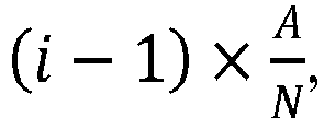
- According to embodiments of the present invention, the wave crests or the wave troughs, on the one side in the height direction of the fin assembly, of all of the plurality of fins are staggered by the predetermined distances relative to one another in the length direction of the fin assembly.
- According to embodiments of the present invention, projections of the wave crests or the wave troughs, on the one side in the height direction of the fin assembly, of all of the plurality of fins on a plane defined by the height direction and the length direction of the fin assembly are arranged at substantially equal intervals in the length direction of the fin assembly.
- According to embodiments of the present invention, at least one of the plurality of fins is provided with no louver.
- According to embodiments of the present invention, the plurality of fins are three or more fins.
- According to embodiments of the present invention, the fin has a sectional shape in a plane that is substantially perpendicular to a surface of the plate of the fin, and at least some of the plurality of fins have substantially the same sectional shape.
- According to embodiments of the present invention, the fin has a sectional shape in a plane that is defined by the height direction and the length direction of the fin assembly, and at least some of the plurality of fins have substantially the same sectional shape.
- According to embodiments of the present invention, there is provided a heat exchanger comprising: heat exchange tubes; and the abovementioned fin assemblies disposed between the heat exchange tubes.
- With the fin assembly and the heat exchanger according to the present invention, for example, heat exchange performance of the heat exchanger can be improved.
-
-
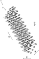
Fig. 1 is a schematic perspective view of a fin assembly according to a first embodiment of the present disclosure; -
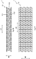
Fig. 2 is a schematic side view of the fin assembly according to the first embodiment of the present disclosure; -
Fig. 3 is another schematic perspective view of the fin assembly according to the first embodiment of the present disclosure; -
Fig. 4 is a schematic side view of a fin assembly according to a second embodiment of the present disclosure; -
Fig. 5 is a schematic perspective view of the fin assembly according to the second embodiment of the present disclosure; -
Fig. 6 is a schematic perspective view of a fin assembly according to a third embodiment of the present disclosure; -
Fig. 7 is a schematic side view of a fin assembly according to a fourth embodiment of the present disclosure; -
Fig. 8 is a schematic perspective view of the fin assembly according to a fourth embodiment of the present disclosure; -
Fig. 9 is a schematic perspective view of a fin assembly according to a fifth embodiment of the present disclosure; -
Fig. 10 is a schematic perspective view of a fin assembly according to a sixth embodiment of the present disclosure; -
Fig. 11 is a schematic top view of the fin assembly according to the sixth embodiment of the present disclosure; -
Fig. 12 is another schematic perspective view of the fin assembly according to the sixth embodiment of the present disclosure ; -
Fig. 13 is a schematic perspective view of a fin assembly according to a seventh embodiment of the present disclosure ; -
Fig. 14 is a schematic top view of the fin assembly according to the seventh embodiment of the present invention; -
Fig. 15 is another schematic perspective view of the fin assembly according to the seventh embodiment of the present invention; -
Fig. 16 is a schematic perspective view of a fin assembly according to an eighth embodiment of the present invention; -
Fig. 17 is a schematic top view of the fin assembly according to the eighth embodiment of the present invention; and -
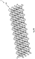
Fig. 18 is another schematic perspective view of the fin assembly according to the eighth embodiment of the present invention. - Embodiments according to the present disclosure are embodiments not forming part of the present invention.
- A further description of the invention will be made as below with reference to embodiments of the present invention taken in conjunction with the accompanying drawings.
- Referring to
Fig. 1 to Fig. 18 , a heat exchanger comprises: heat exchange tubes; andfin assemblies 1 disposed between the heat exchange tubes. - Referring to
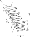
Fig. 1 to Fig. 18 , thefin assembly 1 comprises: a plurality offins 10 each having acorrugated fin body 11 formed by a plate. The plurality offins 10 are arranged side by side in a width direction WD of thefin assembly 1. Wave crests 111 or wavetroughs 112, on one side in a height direction HD of thefin assembly 1, of two adjacent ones of the plurality offins 10 are staggered by a predetermined distance relative to each other in a length direction LD of thefin assembly 1. For example, the plurality offins 10 may be three ormore fins 10. - According to embodiments of the present invention, the
fin 10 has a sectional shape in a plane that is substantially perpendicular to a surface of the plate (or a wave-shaped plate) of thefin 10, and at least some (for example all) of the plurality offins 10 have substantially the same sectional shape. Alternatively, at least some (for example all) of the plurality offins 10 may have different sectional shapes. For example, in a horizontal plane, the plate (or the wave-shaped plate) of thefin 10 or the surface of the plate (or the wave-shaped plate) of thefin 10 is a straight line, and the plane that is substantially perpendicular to the surface of the plate (or the wave-shaped plate) of thefin 10 is perpendicular to the straight line. - According to embodiments of the present invention, the
fin 10 has a sectional shape in a plane that is defined by the height direction HD and the length direction LD of thefin assembly 1, and at least some (for example all) of the plurality offins 10 have substantially the same sectional shape. Alternatively, at least some (for example all) of the plurality offins 10 may have different sectional shapes. - Referring to
Fig. 7 and Fig. 8 , according to embodiments of the present disclosure, the twoadjacent fins 10 are connected to each other. The plurality offins 10 may be integrated. The plurality offins 10 may be formed out of the single plate. With the integrated fin assembly, assembling can be facilitated. In addition, the plurality offins 10 may also be soldered together. - Referring to
Fig. 7 and Fig. 8 , according to an example of the present disclosure, thefin assembly 1 further comprises: aconnection part 100. Theconnection part 100 is arranged between the twoadjacent fins 10 to connect the twoadjacent fins 10. - Referring to
Fig. 7 and Fig. 8 , eachfin body 11 has a top defining thewave crest 111, a bottom defining thewave trough 112, and a middle 113 extending between the top and the bottom, and theconnection part 100 is integrated with themiddles 113 of the twoadjacent fins 10. - Referring to
Fig. 7 and Fig. 8 , eachfin body 11 has a top defining thewave crest 111, a bottom defining thewave trough 112, and a middle 113 extending between the top and the bottom and inclined to the length direction LD of thefin assembly 1, and theconnection part 100 is integrated with themiddles 113 of the twoadjacent fins 10, and is in a position where themiddles 113 of the twoadjacent fins 10 intersect. - Referring to
Fig. 7 and Fig. 8 , theconnection part 100 is arranged at an intermediate part or an intermediate point of the middle 113 in the height direction HD of thefin assembly 1. - Referring to
Figs. 1-3 andFigs. 7-8 , thewave crest 111, on the one side in the height direction HD of thefin assembly 1, of one of the twoadjacent fins 10 and awave trough 112, on the other side in the height direction HD of thefin assembly 1, of the other of the twoadjacent fins 10 are substantially arranged at the same position in the length direction LD of thefin assembly 1. - Referring to
Fig. 4 to Fig. 6 , assuming that the plurality offins 10 are respectively numbered 1st to Nth from one to the other ofoutmost fins 10 of the plurality offins 10, distances by which the wave crests 111 or thewave troughs 112, on the one side in the height direction HD of thefin assembly 1, of the 2nd toNth fins 10 are staggered relative to thewave crest 111 or thewave trough 112, on the one side in the height direction HD of thefin assembly 1, of the1st fin 10 in the length direction LD of thefin assembly 1 are gradually increased by a predetermined increment. For example, the predetermined increment is substantially a constant or a variable. - Referring to
Fig. 4 to Fig. 6 , assuming that the plurality offins 10 are respectively numbered 1st to Nth from one to the other ofoutmost fins 10 of the plurality offins 10, and an average of distances between adjacent ones of the wave crests 111, on the one side in the height direction HD of thefin assembly 1, of thefin assembly 1 is A, a distance by which thewave crest 111 or thewave trough 112, on the one side in the height direction HD of thefin assembly 1, of thenth fin 10 is staggered relative to thewave crest 111 or thewave trough 112, on the one side in the height direction HD of thefin assembly 1, of the1st fin 10 in the length direction LD of thefin assembly 1 is substantially
- Assuming that the plurality of fins 10 are respectively numbered 1st to Nth from one to the other of outmost fins 10 of the plurality of fins 10, a distance by which the wave crest 111 or the wave trough 112, on the one side in the height direction HD of the fin assembly 1, of the ith fin 10 is staggered relative to the wave crest 111 or the wave trough 112, on the one side in the height direction HD of the fin assembly 1, of the 1st fin 10 in the length direction LD of the fin assembly 1 is gradually increased by a predetermined increment, and the wave crest 111, on the one side in the height direction HD of the fin assembly 1, of one of the j-1th and jth fins 10 and a wave trough 112, on the other side in the height direction HD of the fin assembly 1, of the other of the j-lth and jth fins 10 are substantially arranged at the same position in the length direction LD of the fin assembly 1, where i is an odd number that is greater than or equal to 3 and that is less than or equal to N, while j is an even number that is greater than or equal to 2 and that is less than or equal to N. For example, the predetermined increment is substantially a constant.
- Assuming that the plurality of fins 10 are respectively numbered 1st to Nth from one to the other of outmost fins 10 of the plurality of fins 10, the wave crest 111 or the wave trough 112, on the one side in the height direction HD of the fin assembly 1, of the ith fin 10 is staggered by a preset distance relative to the wave crest 111 or the wave trough 112, on the one side in the height direction HD of the fin assembly 1, of the 1st fin 10 in the length direction LD of the fin assembly 1, and the wave crest 111, on the one side in the height direction HD of the fin assembly 1, of one of the j-lth and jth fins 10 and a wave trough 112, on the other side in the height direction HD of the fin assembly 1, of the other of the j-lth and jth fins 10 are substantially arranged at the same position in the length direction LD of the fin assembly 1, where i is an odd number that is greater than or equal to 3 and that is less than or equal to N, while j is an even number that is greater than or equal to 2 and that is less than or equal to N. For example, the distance by which the wave crest 111 or the wave trough 112, on the one side in the height direction HD of the fin assembly 1, of the ith fin 10 is staggered relative to the wave crest 111 or the wave trough 112, on the one side in the height direction HD of the fin assembly 1, of the 1st fin 10 in the length direction LD of the fin assembly 1 is

- The wave crests 111 or the
wave troughs 112, on the one side in the height direction HD of thefin assembly 1, of all of the plurality offins 10 are staggered by the predetermined distances relative to one another in the length direction LD of thefin assembly 1. - Projections of the wave crests 111 or the
wave troughs 112, on the one side in the height direction HD of thefin assembly 1, of all of the plurality offins 10 on a plane defined by the height direction HD and the length direction LD of thefin assembly 1 are arranged at substantially equal intervals in the length direction LD of thefin assembly 1. - Referring to
Fig. 6 , at least two of the plurality offins 10 have different widths from each other. For example, widths of the plurality offins 10 are gradually decreased from one to the other of outmost fins of the plurality offins 10. In addition, eachfin assembly 1 may have other different structural parameters depending on an application. - Referring to
Fig. 9 , at least one of the plurality offins 10 is provided with alouver 115. Alternatively, the plurality offins 10 may be provided with nolouver 115. For example, at least one of the plurality offins 10 is provided with nolouver 115. Referring toFig. 10 to Fig. 18 , according to embodiments of the present invention, in a section perpendicular to the height direction HD of thefin assembly 1, a surface of thefin body 11 of at least one of the plurality offins 10 is inclined to the width direction WD of thefin assembly 1. For example, the section may be between thewave crest 111 and thewave trough 112, for example in the middle 113. With the inclined fins, a wind field can be guided and an air circulating path can be enlarged while a face area is increased. - Referring to
Fig. 10 to Fig. 12 , according to embodiments of the present disclosure, in a section perpendicular to the height direction HD of thefin assembly 1, surfaces of thefin bodies 11 of at least some of the plurality offins 10 are inclined to the width direction WD of thefin assembly 1 towards the same side in the length direction LD of thefin assembly 1. - Referring to
Fig. 13 to Fig. 15 , according to embodiments of the present invention, in a section perpendicular to the height direction HD of thefin assembly 1, a surface of thefin body 11 of at least one (for example one half of the plurality of fins 10), on one side in the width direction WD of thefin assembly 1, of the plurality offins 10 is inclined to the width direction WD of thefin assembly 1 towards one side in the length direction LD of thefin assembly 1, while a surface of thefin body 11 of at least one (for example the other half of the plurality of fins 10), on the other side in the width direction WD of thefin assembly 1, of the plurality offins 10 is inclined to the width direction WD of thefin assembly 1 towards the other side in the length direction LD of thefin assembly 1. With the different inclination directions, a better heat exchange effect can be achieved. - Referring to
Fig. 16 to Fig. 18 , according to embodiments of the present invention, in a section perpendicular to the height direction HD of thefin assembly 1, a surface of thefin body 11 of one of the twoadjacent fins 10 is inclined to the width direction WD of thefin assembly 1 towards one side in the length direction LD of thefin assembly 1, while a surface of thefin body 11 of the other of the twoadjacent fins 10 is inclined to the width direction WD of thefin assembly 1 towards the other side in the length direction LD of thefin assembly 1. - The fin assembly and the heat exchanger according to the embodiments of the present invention have a simple structure and effectively raise heat exchange efficiency of the fin, thereby reducing cost of the heat exchanger and increasing heat exchange capacity of the heat exchanger.
- The fin assembly and the heat exchanger according to the embodiments of the present invention have a more fin face area when viewed from a side view, i.e. as can be seen from an air circulating direction of the heat exchanger. Since wind is sufficiently used, the heat exchange efficiency of the fin is increased.
- In addition, with the fin assembly and the heat exchanger according to the embodiments of the present invention, a rear row of the fin assembly effectively uses wind leaked from the wave crest and the wave trough of a front row of the fin assembly.
- In addition, with the fin assembly and the heat exchanger according to the embodiments of the present invention, a boundary layer occurring during heat exchange can be well broken by increasing the face area of the fin, thereby raising the heat exchange efficiency.
Claims (25)
- A fin assembly (1) for a heat exchanger, the fin assembly (1) comprising:a plurality of fins (10) each having a corrugated fin body (11) formed by a plate, the plurality of fins (10) arranged side by side in a width direction of the fin assembly (1), and a connection part (100),wherein wave crests (111) or wave troughs (112), on one side in a height direction (HD) of the fin assembly (1), of two adjacent ones of the plurality of fins (10) are staggered by a predetermined distance relative to each other in a length direction (LD) of the fin assembly, wherein the wave crests (111) and the wave troughs (112) are connected by a middle (113) inclined to the length direction (LD) of the fin assembly andthe two adjacent fins are connected to each other by the connection part (100) integrated with the middles (113) of the two adjacent fins (10) in a position where the middles (113) of two adjacent fins (10) intersect, characterized in that the middle (113) of at least one of the plurality of fins (10) is inclined to the width direction (WO) of the fin assembly towards a first side in the length direction (LD) of the fin assembly (1) and at least another one of the plurality of fins (10) is inclined to the width direction (WD) of the fin assembly towards a second side in the length direction (LD) of the fin assembly (1), wherein the first side in the length direction (LD) is different to the second side in the length direction (LD).
- The fin assembly for the heat exchanger according to claim 1, wherein
the plurality of fins (10) are integrated. - The fin assembly for the heat exchanger according to claim 1 or 2, wherein
the plurality of fins (10) are formed out of the single plate. - The fin assembly for the heat exchanger according to any of claims 1 to 3, wherein
the connection part is in a position where the middles (113) of the two adjacent fins (10) intersect. - The fin assembly for the heat exchanger according to any of claims 1 to 4, wherein
the connection part (100) is arranged at an intermediate part of the middle (113) in the height direction (HD) of the fin assembly. - The fin assembly for the heat exchanger according to claim 1, wherein
the wave crest (111), on the one side in the height direction (HD) of the fin assembly (1), of one of the two adjacent fins (10) and a wave trough (112), on the other side in the height direction (HD) of the fin assembly (1), of the other of the two adjacent fins (10) are substantially arranged at the same position in the length direction (LD) of the fin assembly. - The fin assembly for the heat exchanger according to claim 1, wherein
assuming that the plurality of fins (10) are respectively numbered 1st to Nth from one to the other of outmost fins (10) of the plurality of fins (10), distances by which the wave crests (111) or the wave troughs (112), on the one side in the height direction (HD) of the fin assembly (1), of the 2nd to Nth fins are staggered relative to the wave crest (111) or the wave trough (112), on the one side in the height direction (HD) of the fin assembly (1), of the 1st fin in the length direction (LD) of the fin assembly are gradually increased by a predetermined increment. - The fin assembly for the heat exchanger according to claim 7, wherein
the predetermined increment is substantially a constant. - The fin assembly for the heat exchanger according to claim 1, wherein
assuming that the plurality of fins (10) are respectively numbered 1st to Nth from one to the other of outmost fins of the plurality of fins (10), and an average of distances between adjacent ones of the wave crests (111), on the one side in the height direction (HD) of the fin assembly (1), of the fin assembly is A, a distance by which the wave crest (111) or the wave trough (112), on the one side in the height direction (HD) of the fin assembly (1), of the nth fin is staggered relative to the wave crest (111) or the wave trough (112), on the one side in the height direction (HD) of the fin assembly (1), of the 1st fin in the length direction (LD) of the fin assembly is substantially
- The fin assembly for the heat exchanger according to claim 1, wherein
at least two of the plurality of fins (10) have different widths from each other. - The fin assembly for the heat exchanger according to claim 1, wherein
at least one of the plurality of fins (10) is provided with a louver (115). - The fin assembly for the heat exchanger according to any of claims 1 to 11, wherein
in the section perpendicular to the height direction (HD) of the fin assembly (1), surfaces of the fin bodies (11) of at least some of the plurality of fins (10) are inclined to the width direction (WD) of the fin assembly towards the same side in the length direction (LD) of the fin assembly. - The fin assembly for the heat exchanger according to any of claims 1 to 11, wherein
in the section perpendicular to the height direction (HD) of the fin assembly (1), a surface of the fin body (11) of at least one, on one side in the width direction (WD) of the fin assembly (1), of the plurality of fins (10) is inclined to the width direction (WD) of the fin assembly (1) towards one side in the length direction (LD) of the fin assembly, while a surface of the fin body (11) of at least one, on the other side in the width direction (WD) of the fin assembly (1), of the plurality of fins (10) is inclined to the width direction (WD) of the fin assembly (1) towards the other side in the length direction of the fin assembly. - The fin assembly for the heat exchanger according to any of claims 1 to 11, wherein
in the section perpendicular to the height direction (HD) of the fin assembly (1), a surface of the fin body (11) of one of the two adjacent fins (10) is inclined to the width direction (WD) of the fin assembly (1) towards one side in the length direction (LD) of the fin assembly (1), while a surface of the fin body (11) of the other of the two adjacent fins (10) is inclined to the width direction (WD) of the fin assembly towards the other side in the length direction (LD) of the fin assembly. - The fin assembly for the heat exchanger according to claim 1, wherein
assuming that the plurality of fins (10) are respectively numbered 1st to Nth from one to the other of outmost fins of the plurality of fins (10), a distance by which the wave crest (111) or the wave trough (112), on the one side in the height direction (HD) of the fin assembly, of the ith fin is staggered relative to the wave crest (111) or the wave trough (112), on the one side in the height direction (HD) of the fin assembly, of the 1st fin in the length direction (LD) of the fin assembly (1) is gradually increased by a predetermined increment, and the wave crest (111), on the one side in the height direction (HD) of the fin assembly, of one of the j-1th and jth fins and a wave trough (112), on the other side in the height direction (HD) of the fin assembly (1), of the other of the j-1th and jth fins (10) are substantially arranged at the same position in the length direction (LD) of the fin assembly, where i is an odd number that is greater than or equal to 3 and that is less than or equal to N, while j is an even number that is greater than or equal to 2 and that is less than or equal to N. - The fin assembly for the heat exchanger according to claim 15, wherein
the predetermined increment is substantially a constant. - The fin assembly for the heat exchanger according to claim 1, wherein
assuming that the plurality of fins (10) are respectively numbered 1st to Nth from one to the other of outmost fins of the plurality of fins (10), the wave crest (111) or the wave trough (112), on the one side in the height direction (HD) of the fin assembly (1), of the ith fin is staggered by a preset distance relative to the wave crest (111) or the wave trough (112), on the one side in the height direction (HD) of the fin assembly (1), of the 1st fin in the length direction (LD) of the fin assembly (1), and the wave crest (111), on the one side in the height direction (HD) of the fin assembly, of one of the j-1th and jth fins and a wave trough (112), on the other side in the height direction (LD) of the fin assembly, of the other of the j-1th and jth fins are substantially arranged at the same position in the length direction of the fin assembly, where i is an odd number that is greater than or equal to 3 and that is less than or equal to N, while j is an even number that is greater than or equal to 2 and that is less than or equal to N. - The fin assembly for the heat exchanger according to claim 17, wherein
the distance by which the wave crest (111) or the wave trough (112), on the one side in the height direction (HD) of the fin assembly, of the ith fin is staggered relative to the wave crest (111) or the wave trough (112), on the one side in the height direction (HD) of the fin assembly, of the 1st fin in the length direction of the fin assembly is
- The fin assembly for the heat exchanger according to claim 1, wherein
the wave crests (111) or the wave troughs (112), on the one side in the height direction (HD) of the fin assembly, of all of the plurality of fins (10) are staggered by the predetermined distances relative to one another in the length direction (LD) of the fin assembly. - The fin assembly for the heat exchanger according to claim 1, wherein
projections of the wave crests (111) or the wave troughs (112), on the one side in the height direction (HD) of the fin assembly, of all of the plurality of fins (10) on a plane defined by the height direction (HD) and the length direction (LD) of the fin assembly are arranged at substantially equal intervals in the length direction (LD) of the fin assembly. - The fin assembly for the heat exchanger according to claim 1, wherein
at least one of the plurality of fins (10) is provided with no louver (115). - The fin assembly for the heat exchanger according to claim 1, wherein
the plurality of fins (10) are three or more fins. - The fin assembly for the heat exchanger according to claim 1, wherein
the fin (10) has a sectional shape in a plane that is substantially perpendicular to a surface of the plate of the fin (10), and at least some of the plurality of fins (10) have substantially the same sectional shape. - The fin assembly for the heat exchanger according to claim 1, wherein
the fin (10) has a sectional shape in a plane that is defined by the height direction and the length direction of the fin assembly, and at least some of the plurality of fins (10) have substantially the same sectional shape. - A heat exchanger, comprising:heat exchange tubes; andthe fin assemblies (1) according to claim 1 which are disposed between the heat exchange tubes.
Applications Claiming Priority (2)
| Application Number | Priority Date | Filing Date | Title |
|---|---|---|---|
| CN201510455325.3A CN106643263B (en) | 2015-07-29 | 2015-07-29 | Fin assembly for heat exchanger and heat exchanger with fin assembly |
| PCT/CN2016/090431 WO2017016414A1 (en) | 2015-07-29 | 2016-07-19 | Fin assembly for heat exchanger and heat exchanger having same |
Publications (3)
| Publication Number | Publication Date |
|---|---|
| EP3330658A1 EP3330658A1 (en) | 2018-06-06 |
| EP3330658A4 EP3330658A4 (en) | 2019-01-30 |
| EP3330658B1 true EP3330658B1 (en) | 2021-09-08 |
Family
ID=57884133
Family Applications (1)
| Application Number | Title | Priority Date | Filing Date |
|---|---|---|---|
| EP16829780.2A Not-in-force EP3330658B1 (en) | 2015-07-29 | 2016-07-19 | Fin assembly for heat exchanger and heat exchanger having same |
Country Status (6)
| Country | Link |
|---|---|
| US (1) | US10816278B2 (en) |
| EP (1) | EP3330658B1 (en) |
| JP (1) | JP2018521293A (en) |
| KR (1) | KR102590069B1 (en) |
| CN (1) | CN106643263B (en) |
| WO (1) | WO2017016414A1 (en) |
Families Citing this family (17)
| Publication number | Priority date | Publication date | Assignee | Title |
|---|---|---|---|---|
| CN107204314A (en) * | 2017-06-30 | 2017-09-26 | 上海嘉熙科技有限公司 | Hot superconductive radiating component and its manufacture method |
| CN107359146B (en) * | 2017-06-30 | 2020-01-24 | 上海嘉熙科技有限公司 | Heat superconducting plate fin type radiator with fins on surface |
| CN108106469B (en) * | 2018-01-26 | 2023-08-25 | 上海交通大学 | A plate-fin heat exchanger fin assembly and heat exchanger suitable for shaking conditions |
| US20200166293A1 (en) * | 2018-11-27 | 2020-05-28 | Hamilton Sundstrand Corporation | Weaved cross-flow heat exchanger and method of forming a heat exchanger |
| JP6926183B2 (en) * | 2019-12-19 | 2021-08-25 | 東芝電波プロダクツ株式会社 | Dissipator |
| FR3106001B1 (en) * | 2020-01-03 | 2022-12-02 | Valeo Systemes Thermiques | Tube heat exchanger with spacers |
| FR3106000B1 (en) * | 2020-01-03 | 2022-01-14 | Valeo Systemes Thermiques | Tube heat exchanger with spacers |
| US20220260316A1 (en) * | 2020-12-16 | 2022-08-18 | Meggitt Aerospace Limited | Cross-flow heat exchangers and methods of making the same |
| CN113834367A (en) * | 2021-08-20 | 2021-12-24 | 浙江银轮机械股份有限公司 | Heat exchange fin and heat exchanger |
| US12405070B2 (en) * | 2022-01-04 | 2025-09-02 | Carrier Corporation | Corrosion resistant microchannel heat exchanger |
| CN217585468U (en) * | 2022-05-26 | 2022-10-14 | 广东英维克技术有限公司 | Fin assembly and evaporator thereof |
| WO2024023908A1 (en) * | 2022-07-26 | 2024-02-01 | 三菱電機株式会社 | Heat exchanger and refrigeration cycle device |
| US20240263884A1 (en) * | 2023-02-06 | 2024-08-08 | Raytheon Technologies Corporation | Conformal heat exchanger with triangular offset strip fins |
| CN220545357U (en) * | 2023-07-14 | 2024-02-27 | 惠州市讯硕科技有限公司 | Overlapped cooling fin water cooling row |
| CN118224900A (en) * | 2023-09-26 | 2024-06-21 | 比亚迪股份有限公司 | Heat exchangers, heat exchange systems and vehicles |
| WO2025196940A1 (en) * | 2024-03-19 | 2025-09-25 | 三菱電機株式会社 | Heat exchanger and refrigeration cycle device comprising said heat exchanger |
| CN121048424A (en) * | 2024-05-30 | 2025-12-02 | 绍兴三花汽车热管理科技有限公司 | A finned heat exchanger |
Family Cites Families (24)
| Publication number | Priority date | Publication date | Assignee | Title |
|---|---|---|---|---|
| US3045979A (en) * | 1956-03-07 | 1962-07-24 | Modine Mfg Co | Staggered serpentine structure for heat exchanges and method and means for making the same |
| JP3322533B2 (en) | 1995-08-24 | 2002-09-09 | カルソニックカンセイ株式会社 | Fin for integrated heat exchanger |
| JPH10300375A (en) * | 1997-04-28 | 1998-11-13 | Hitachi Ltd | Heat exchanger |
| JP4158225B2 (en) | 1997-07-25 | 2008-10-01 | 株式会社デンソー | Heat exchanger and housing cooling device |
| FR2785978B1 (en) * | 1998-11-16 | 2001-03-30 | Valeo Thermique Moteur Sa | MULTIPLE HEAT EXCHANGER WITH COMMON INSERTS |
| JP4207331B2 (en) * | 1999-09-29 | 2009-01-14 | 株式会社デンソー | Double heat exchanger |
| US20030102113A1 (en) * | 2001-11-30 | 2003-06-05 | Stephen Memory | Heat exchanger for providing supercritical cooling of a working fluid in a transcritical cooling cycle |
| JP2004020108A (en) * | 2002-06-18 | 2004-01-22 | Denso Corp | Heat exchanger |
| JP2005061648A (en) * | 2003-08-18 | 2005-03-10 | Zexel Valeo Climate Control Corp | Heat exchanger |
| DE10342241A1 (en) * | 2003-09-11 | 2005-04-07 | Behr Gmbh & Co. Kg | heat exchangers |
| CN100417910C (en) * | 2006-06-01 | 2008-09-10 | 东南大学 | Fractal sawtooth fin |
| US9891008B2 (en) * | 2007-01-25 | 2018-02-13 | The University Of Tokyo | Heat exchanger |
| CN101995185A (en) * | 2010-11-02 | 2011-03-30 | 三花丹佛斯(杭州)微通道换热器有限公司 | Fin for heat exchanger and heat exchanger with same |
| RU2568230C2 (en) * | 2010-12-22 | 2015-11-10 | Флексэнерджи Энерджи Системз, Инк. | Heat exchanger with secondary folding |
| US9080819B2 (en) * | 2011-10-05 | 2015-07-14 | T.Rad Co., Ltd. | Folded heat exchanger with V-shaped convex portions |
| JP5967588B2 (en) * | 2011-10-19 | 2016-08-10 | パナソニックIpマネジメント株式会社 | Heat exchanger |
| WO2013082569A1 (en) * | 2011-12-02 | 2013-06-06 | Huawei Technologies Co., Ltd. | Apparatus and method for reducing traffic on a unified optical and coaxial network |
| JP5772608B2 (en) * | 2012-01-12 | 2015-09-02 | 株式会社デンソー | Heat exchanger |
| JP2014074562A (en) * | 2012-10-05 | 2014-04-24 | Calsonic Kansei Corp | Offset fin of heat exchanger and forming method of the same |
| CN103389001A (en) * | 2013-07-29 | 2013-11-13 | 无锡方盛换热器制造有限公司 | Fin structure for heat exchangers |
| CN203572292U (en) * | 2013-11-15 | 2014-04-30 | 上海双桦汽车零部件股份有限公司 | Fin structure for intercooler |
| CN204286173U (en) * | 2014-11-05 | 2015-04-22 | 中国船舶重工集团公司第七�三研究所 | Zigzag wave corrugated fin plate-fin heat exchanger |
| CN204202451U (en) * | 2014-11-13 | 2015-03-11 | 中国船舶重工集团公司第七�三研究所 | Zigzag louvered fin type plate-fin heat exchanger |
| CN204924000U (en) * | 2015-07-29 | 2015-12-30 | 丹佛斯微通道换热器(嘉兴)有限公司 | Fin assembly for heat exchanger and heat exchanger with same |
-
2015
- 2015-07-29 CN CN201510455325.3A patent/CN106643263B/en not_active Expired - Fee Related
-
2016
- 2016-07-19 KR KR1020187004937A patent/KR102590069B1/en active Active
- 2016-07-19 JP JP2018503763A patent/JP2018521293A/en active Pending
- 2016-07-19 US US15/744,342 patent/US10816278B2/en active Active
- 2016-07-19 EP EP16829780.2A patent/EP3330658B1/en not_active Not-in-force
- 2016-07-19 WO PCT/CN2016/090431 patent/WO2017016414A1/en not_active Ceased
Also Published As
| Publication number | Publication date |
|---|---|
| CN106643263B (en) | 2019-02-15 |
| US20190086160A1 (en) | 2019-03-21 |
| WO2017016414A1 (en) | 2017-02-02 |
| KR102590069B1 (en) | 2023-10-16 |
| JP2018521293A (en) | 2018-08-02 |
| CN106643263A (en) | 2017-05-10 |
| KR20180034503A (en) | 2018-04-04 |
| EP3330658A4 (en) | 2019-01-30 |
| EP3330658A1 (en) | 2018-06-06 |
| US10816278B2 (en) | 2020-10-27 |
Similar Documents
| Publication | Publication Date | Title |
|---|---|---|
| US10816278B2 (en) | Fin assembly for heat exchanger and heat exchanger having the fin assembly | |
| CN204924000U (en) | Fin assembly for heat exchanger and heat exchanger with same | |
| EP2295919B1 (en) | Fin and heat exchanger having the same | |
| EP2840341B1 (en) | Heat exchanger | |
| US6431263B2 (en) | Heat exchanger with small-diameter refrigerant tubes | |
| JP2018521293A5 (en) | ||
| US9423184B2 (en) | Drainage structure for corrugated-fin heat exchanger | |
| WO2018054319A1 (en) | Heat exchanger core and heat exchanger having same | |
| EP2693150B1 (en) | Heat exchanger | |
| JP7749314B2 (en) | Heat exchanger and air conditioner using this heat exchanger | |
| EP3171114A1 (en) | Fin for heat exchanger and heat exchanger having fin | |
| EP2693151B1 (en) | Heat exchanger | |
| WO2013001744A1 (en) | Fin tube heat exchanger | |
| JP2013245884A (en) | Fin tube heat exchanger | |
| US6942024B2 (en) | Corrugated heat exchange element | |
| US20090173479A1 (en) | Louvered air center for compact heat exchanger | |
| WO2014126634A1 (en) | Multiple bank flattened tube heat exchanger | |
| JP5958917B2 (en) | Finned tube heat exchanger | |
| US10094624B2 (en) | Fin for heat exchanger | |
| EP3904808A1 (en) | Heat exchanger | |
| CN108253833B (en) | Fin component for heat exchanger and the heat exchanger with the fin component | |
| JP6194471B2 (en) | Finned tube heat exchanger | |
| CN108413805B (en) | Heat sink | |
| CN102252548B (en) | Fin for heat exchanger and heat exchanger with fin | |
| JPH0547974Y2 (en) |
Legal Events
| Date | Code | Title | Description |
|---|---|---|---|
| STAA | Information on the status of an ep patent application or granted ep patent |
Free format text: STATUS: THE INTERNATIONAL PUBLICATION HAS BEEN MADE |
|
| PUAI | Public reference made under article 153(3) epc to a published international application that has entered the european phase |
Free format text: ORIGINAL CODE: 0009012 |
|
| STAA | Information on the status of an ep patent application or granted ep patent |
Free format text: STATUS: REQUEST FOR EXAMINATION WAS MADE |
|
| 17P | Request for examination filed |
Effective date: 20180104 |
|
| AK | Designated contracting states |
Kind code of ref document: A1 Designated state(s): AL AT BE BG CH CY CZ DE DK EE ES FI FR GB GR HR HU IE IS IT LI LT LU LV MC MK MT NL NO PL PT RO RS SE SI SK SM TR |
|
| AX | Request for extension of the european patent |
Extension state: BA ME |
|
| DAV | Request for validation of the european patent (deleted) | ||
| DAX | Request for extension of the european patent (deleted) | ||
| A4 | Supplementary search report drawn up and despatched |
Effective date: 20190107 |
|
| RIC1 | Information provided on ipc code assigned before grant |
Ipc: F28F 1/22 20060101ALI20181221BHEP Ipc: F28F 3/04 20060101AFI20181221BHEP |
|
| STAA | Information on the status of an ep patent application or granted ep patent |
Free format text: STATUS: EXAMINATION IS IN PROGRESS |
|
| 17Q | First examination report despatched |
Effective date: 20190712 |
|
| GRAP | Despatch of communication of intention to grant a patent |
Free format text: ORIGINAL CODE: EPIDOSNIGR1 |
|
| STAA | Information on the status of an ep patent application or granted ep patent |
Free format text: STATUS: GRANT OF PATENT IS INTENDED |
|
| INTG | Intention to grant announced |
Effective date: 20210429 |
|
| GRAS | Grant fee paid |
Free format text: ORIGINAL CODE: EPIDOSNIGR3 |
|
| GRAA | (expected) grant |
Free format text: ORIGINAL CODE: 0009210 |
|
| STAA | Information on the status of an ep patent application or granted ep patent |
Free format text: STATUS: THE PATENT HAS BEEN GRANTED |
|
| AK | Designated contracting states |
Kind code of ref document: B1 Designated state(s): AL AT BE BG CH CY CZ DE DK EE ES FI FR GB GR HR HU IE IS IT LI LT LU LV MC MK MT NL NO PL PT RO RS SE SI SK SM TR |
|
| REG | Reference to a national code |
Ref country code: GB Ref legal event code: FG4D |
|
| REG | Reference to a national code |
Ref country code: AT Ref legal event code: REF Ref document number: 1428945 Country of ref document: AT Kind code of ref document: T Effective date: 20210915 Ref country code: CH Ref legal event code: EP |
|
| REG | Reference to a national code |
Ref country code: IE Ref legal event code: FG4D |
|
| REG | Reference to a national code |
Ref country code: DE Ref legal event code: R096 Ref document number: 602016063526 Country of ref document: DE |
|
| REG | Reference to a national code |
Ref country code: LT Ref legal event code: MG9D |
|
| REG | Reference to a national code |
Ref country code: NL Ref legal event code: MP Effective date: 20210908 |
|
| PG25 | Lapsed in a contracting state [announced via postgrant information from national office to epo] |
Ref country code: RS Free format text: LAPSE BECAUSE OF FAILURE TO SUBMIT A TRANSLATION OF THE DESCRIPTION OR TO PAY THE FEE WITHIN THE PRESCRIBED TIME-LIMIT Effective date: 20210908 Ref country code: SE Free format text: LAPSE BECAUSE OF FAILURE TO SUBMIT A TRANSLATION OF THE DESCRIPTION OR TO PAY THE FEE WITHIN THE PRESCRIBED TIME-LIMIT Effective date: 20210908 Ref country code: LT Free format text: LAPSE BECAUSE OF FAILURE TO SUBMIT A TRANSLATION OF THE DESCRIPTION OR TO PAY THE FEE WITHIN THE PRESCRIBED TIME-LIMIT Effective date: 20210908 Ref country code: BG Free format text: LAPSE BECAUSE OF FAILURE TO SUBMIT A TRANSLATION OF THE DESCRIPTION OR TO PAY THE FEE WITHIN THE PRESCRIBED TIME-LIMIT Effective date: 20211208 Ref country code: NO Free format text: LAPSE BECAUSE OF FAILURE TO SUBMIT A TRANSLATION OF THE DESCRIPTION OR TO PAY THE FEE WITHIN THE PRESCRIBED TIME-LIMIT Effective date: 20211208 Ref country code: HR Free format text: LAPSE BECAUSE OF FAILURE TO SUBMIT A TRANSLATION OF THE DESCRIPTION OR TO PAY THE FEE WITHIN THE PRESCRIBED TIME-LIMIT Effective date: 20210908 Ref country code: FI Free format text: LAPSE BECAUSE OF FAILURE TO SUBMIT A TRANSLATION OF THE DESCRIPTION OR TO PAY THE FEE WITHIN THE PRESCRIBED TIME-LIMIT Effective date: 20210908 Ref country code: ES Free format text: LAPSE BECAUSE OF FAILURE TO SUBMIT A TRANSLATION OF THE DESCRIPTION OR TO PAY THE FEE WITHIN THE PRESCRIBED TIME-LIMIT Effective date: 20210908 |
|
| REG | Reference to a national code |
Ref country code: AT Ref legal event code: MK05 Ref document number: 1428945 Country of ref document: AT Kind code of ref document: T Effective date: 20210908 |
|
| PG25 | Lapsed in a contracting state [announced via postgrant information from national office to epo] |
Ref country code: LV Free format text: LAPSE BECAUSE OF FAILURE TO SUBMIT A TRANSLATION OF THE DESCRIPTION OR TO PAY THE FEE WITHIN THE PRESCRIBED TIME-LIMIT Effective date: 20210908 Ref country code: GR Free format text: LAPSE BECAUSE OF FAILURE TO SUBMIT A TRANSLATION OF THE DESCRIPTION OR TO PAY THE FEE WITHIN THE PRESCRIBED TIME-LIMIT Effective date: 20211209 |
|
| PG25 | Lapsed in a contracting state [announced via postgrant information from national office to epo] |
Ref country code: AT Free format text: LAPSE BECAUSE OF FAILURE TO SUBMIT A TRANSLATION OF THE DESCRIPTION OR TO PAY THE FEE WITHIN THE PRESCRIBED TIME-LIMIT Effective date: 20210908 |
|
| PG25 | Lapsed in a contracting state [announced via postgrant information from national office to epo] |
Ref country code: IS Free format text: LAPSE BECAUSE OF FAILURE TO SUBMIT A TRANSLATION OF THE DESCRIPTION OR TO PAY THE FEE WITHIN THE PRESCRIBED TIME-LIMIT Effective date: 20220108 Ref country code: SM Free format text: LAPSE BECAUSE OF FAILURE TO SUBMIT A TRANSLATION OF THE DESCRIPTION OR TO PAY THE FEE WITHIN THE PRESCRIBED TIME-LIMIT Effective date: 20210908 Ref country code: SK Free format text: LAPSE BECAUSE OF FAILURE TO SUBMIT A TRANSLATION OF THE DESCRIPTION OR TO PAY THE FEE WITHIN THE PRESCRIBED TIME-LIMIT Effective date: 20210908 Ref country code: RO Free format text: LAPSE BECAUSE OF FAILURE TO SUBMIT A TRANSLATION OF THE DESCRIPTION OR TO PAY THE FEE WITHIN THE PRESCRIBED TIME-LIMIT Effective date: 20210908 Ref country code: PT Free format text: LAPSE BECAUSE OF FAILURE TO SUBMIT A TRANSLATION OF THE DESCRIPTION OR TO PAY THE FEE WITHIN THE PRESCRIBED TIME-LIMIT Effective date: 20220110 Ref country code: PL Free format text: LAPSE BECAUSE OF FAILURE TO SUBMIT A TRANSLATION OF THE DESCRIPTION OR TO PAY THE FEE WITHIN THE PRESCRIBED TIME-LIMIT Effective date: 20210908 Ref country code: NL Free format text: LAPSE BECAUSE OF FAILURE TO SUBMIT A TRANSLATION OF THE DESCRIPTION OR TO PAY THE FEE WITHIN THE PRESCRIBED TIME-LIMIT Effective date: 20210908 Ref country code: EE Free format text: LAPSE BECAUSE OF FAILURE TO SUBMIT A TRANSLATION OF THE DESCRIPTION OR TO PAY THE FEE WITHIN THE PRESCRIBED TIME-LIMIT Effective date: 20210908 Ref country code: CZ Free format text: LAPSE BECAUSE OF FAILURE TO SUBMIT A TRANSLATION OF THE DESCRIPTION OR TO PAY THE FEE WITHIN THE PRESCRIBED TIME-LIMIT Effective date: 20210908 Ref country code: AL Free format text: LAPSE BECAUSE OF FAILURE TO SUBMIT A TRANSLATION OF THE DESCRIPTION OR TO PAY THE FEE WITHIN THE PRESCRIBED TIME-LIMIT Effective date: 20210908 |
|
| REG | Reference to a national code |
Ref country code: DE Ref legal event code: R097 Ref document number: 602016063526 Country of ref document: DE |
|
| PLBE | No opposition filed within time limit |
Free format text: ORIGINAL CODE: 0009261 |
|
| STAA | Information on the status of an ep patent application or granted ep patent |
Free format text: STATUS: NO OPPOSITION FILED WITHIN TIME LIMIT |
|
| PG25 | Lapsed in a contracting state [announced via postgrant information from national office to epo] |
Ref country code: DK Free format text: LAPSE BECAUSE OF FAILURE TO SUBMIT A TRANSLATION OF THE DESCRIPTION OR TO PAY THE FEE WITHIN THE PRESCRIBED TIME-LIMIT Effective date: 20210908 |
|
| 26N | No opposition filed |
Effective date: 20220609 |
|
| PG25 | Lapsed in a contracting state [announced via postgrant information from national office to epo] |
Ref country code: SI Free format text: LAPSE BECAUSE OF FAILURE TO SUBMIT A TRANSLATION OF THE DESCRIPTION OR TO PAY THE FEE WITHIN THE PRESCRIBED TIME-LIMIT Effective date: 20210908 |
|
| PG25 | Lapsed in a contracting state [announced via postgrant information from national office to epo] |
Ref country code: IT Free format text: LAPSE BECAUSE OF FAILURE TO SUBMIT A TRANSLATION OF THE DESCRIPTION OR TO PAY THE FEE WITHIN THE PRESCRIBED TIME-LIMIT Effective date: 20210908 |
|
| PG25 | Lapsed in a contracting state [announced via postgrant information from national office to epo] |
Ref country code: MC Free format text: LAPSE BECAUSE OF FAILURE TO SUBMIT A TRANSLATION OF THE DESCRIPTION OR TO PAY THE FEE WITHIN THE PRESCRIBED TIME-LIMIT Effective date: 20210908 |
|
| REG | Reference to a national code |
Ref country code: CH Ref legal event code: PL |
|
| REG | Reference to a national code |
Ref country code: BE Ref legal event code: MM Effective date: 20220731 |
|
| PG25 | Lapsed in a contracting state [announced via postgrant information from national office to epo] |
Ref country code: LU Free format text: LAPSE BECAUSE OF NON-PAYMENT OF DUE FEES Effective date: 20220719 Ref country code: LI Free format text: LAPSE BECAUSE OF NON-PAYMENT OF DUE FEES Effective date: 20220731 Ref country code: CH Free format text: LAPSE BECAUSE OF NON-PAYMENT OF DUE FEES Effective date: 20220731 |
|
| PG25 | Lapsed in a contracting state [announced via postgrant information from national office to epo] |
Ref country code: BE Free format text: LAPSE BECAUSE OF NON-PAYMENT OF DUE FEES Effective date: 20220731 |
|
| P01 | Opt-out of the competence of the unified patent court (upc) registered |
Effective date: 20230621 |
|
| PG25 | Lapsed in a contracting state [announced via postgrant information from national office to epo] |
Ref country code: IE Free format text: LAPSE BECAUSE OF NON-PAYMENT OF DUE FEES Effective date: 20220719 |
|
| PGFP | Annual fee paid to national office [announced via postgrant information from national office to epo] |
Ref country code: FR Payment date: 20230622 Year of fee payment: 8 |
|
| PGFP | Annual fee paid to national office [announced via postgrant information from national office to epo] |
Ref country code: GB Payment date: 20230601 Year of fee payment: 8 |
|
| PGFP | Annual fee paid to national office [announced via postgrant information from national office to epo] |
Ref country code: DE Payment date: 20230607 Year of fee payment: 8 |
|
| PG25 | Lapsed in a contracting state [announced via postgrant information from national office to epo] |
Ref country code: HU Free format text: LAPSE BECAUSE OF FAILURE TO SUBMIT A TRANSLATION OF THE DESCRIPTION OR TO PAY THE FEE WITHIN THE PRESCRIBED TIME-LIMIT; INVALID AB INITIO Effective date: 20160719 |
|
| PG25 | Lapsed in a contracting state [announced via postgrant information from national office to epo] |
Ref country code: MK Free format text: LAPSE BECAUSE OF FAILURE TO SUBMIT A TRANSLATION OF THE DESCRIPTION OR TO PAY THE FEE WITHIN THE PRESCRIBED TIME-LIMIT Effective date: 20210908 Ref country code: CY Free format text: LAPSE BECAUSE OF FAILURE TO SUBMIT A TRANSLATION OF THE DESCRIPTION OR TO PAY THE FEE WITHIN THE PRESCRIBED TIME-LIMIT Effective date: 20210908 |
|
| PG25 | Lapsed in a contracting state [announced via postgrant information from national office to epo] |
Ref country code: MT Free format text: LAPSE BECAUSE OF FAILURE TO SUBMIT A TRANSLATION OF THE DESCRIPTION OR TO PAY THE FEE WITHIN THE PRESCRIBED TIME-LIMIT Effective date: 20210908 |
|
| REG | Reference to a national code |
Ref country code: DE Ref legal event code: R119 Ref document number: 602016063526 Country of ref document: DE |
|
| GBPC | Gb: european patent ceased through non-payment of renewal fee |
Effective date: 20240719 |
|
| PG25 | Lapsed in a contracting state [announced via postgrant information from national office to epo] |
Ref country code: DE Free format text: LAPSE BECAUSE OF NON-PAYMENT OF DUE FEES Effective date: 20250201 |
|
| PG25 | Lapsed in a contracting state [announced via postgrant information from national office to epo] |
Ref country code: FR Free format text: LAPSE BECAUSE OF NON-PAYMENT OF DUE FEES Effective date: 20240731 |
|
| PG25 | Lapsed in a contracting state [announced via postgrant information from national office to epo] |
Ref country code: GB Free format text: LAPSE BECAUSE OF NON-PAYMENT OF DUE FEES Effective date: 20240719 |
|
| PG25 | Lapsed in a contracting state [announced via postgrant information from national office to epo] |
Ref country code: TR Free format text: LAPSE BECAUSE OF FAILURE TO SUBMIT A TRANSLATION OF THE DESCRIPTION OR TO PAY THE FEE WITHIN THE PRESCRIBED TIME-LIMIT Effective date: 20210908 |