EP3330483A1 - Vakuumpumpe mit einer kupplungsanordnung zur kompensation von wellenexzentrizitäten - Google Patents
Vakuumpumpe mit einer kupplungsanordnung zur kompensation von wellenexzentrizitäten Download PDFInfo
- Publication number
- EP3330483A1 EP3330483A1 EP16202237.0A EP16202237A EP3330483A1 EP 3330483 A1 EP3330483 A1 EP 3330483A1 EP 16202237 A EP16202237 A EP 16202237A EP 3330483 A1 EP3330483 A1 EP 3330483A1
- Authority
- EP
- European Patent Office
- Prior art keywords
- clutch
- clutch hub
- clutch disc
- cams
- hub
- Prior art date
- Legal status (The legal status is an assumption and is not a legal conclusion. Google has not performed a legal analysis and makes no representation as to the accuracy of the status listed.)
- Granted
Links
Images


Classifications
-
- F—MECHANICAL ENGINEERING; LIGHTING; HEATING; WEAPONS; BLASTING
- F04—POSITIVE - DISPLACEMENT MACHINES FOR LIQUIDS; PUMPS FOR LIQUIDS OR ELASTIC FLUIDS
- F04C—ROTARY-PISTON, OR OSCILLATING-PISTON, POSITIVE-DISPLACEMENT MACHINES FOR LIQUIDS; ROTARY-PISTON, OR OSCILLATING-PISTON, POSITIVE-DISPLACEMENT PUMPS
- F04C18/00—Rotary-piston pumps specially adapted for elastic fluids
- F04C18/30—Rotary-piston pumps specially adapted for elastic fluids having the characteristics covered by two or more of groups F04C18/02, F04C18/08, F04C18/22, F04C18/24, F04C18/48, or having the characteristics covered by one of these groups together with some other type of movement between co-operating members
- F04C18/34—Rotary-piston pumps specially adapted for elastic fluids having the characteristics covered by two or more of groups F04C18/02, F04C18/08, F04C18/22, F04C18/24, F04C18/48, or having the characteristics covered by one of these groups together with some other type of movement between co-operating members having the movement defined in group F04C18/08 or F04C18/22 and relative reciprocation between the co-operating members
- F04C18/344—Rotary-piston pumps specially adapted for elastic fluids having the characteristics covered by two or more of groups F04C18/02, F04C18/08, F04C18/22, F04C18/24, F04C18/48, or having the characteristics covered by one of these groups together with some other type of movement between co-operating members having the movement defined in group F04C18/08 or F04C18/22 and relative reciprocation between the co-operating members with vanes reciprocating with respect to the inner member
-
- F—MECHANICAL ENGINEERING; LIGHTING; HEATING; WEAPONS; BLASTING
- F01—MACHINES OR ENGINES IN GENERAL; ENGINE PLANTS IN GENERAL; STEAM ENGINES
- F01C—ROTARY-PISTON OR OSCILLATING-PISTON MACHINES OR ENGINES
- F01C17/00—Arrangements for drive of co-operating members, e.g. for rotary piston and casing
- F01C17/06—Arrangements for drive of co-operating members, e.g. for rotary piston and casing using cranks, universal joints or similar elements
- F01C17/066—Arrangements for drive of co-operating members, e.g. for rotary piston and casing using cranks, universal joints or similar elements with an intermediate piece sliding along perpendicular axes, e.g. Oldham coupling
-
- F—MECHANICAL ENGINEERING; LIGHTING; HEATING; WEAPONS; BLASTING
- F04—POSITIVE - DISPLACEMENT MACHINES FOR LIQUIDS; PUMPS FOR LIQUIDS OR ELASTIC FLUIDS
- F04C—ROTARY-PISTON, OR OSCILLATING-PISTON, POSITIVE-DISPLACEMENT MACHINES FOR LIQUIDS; ROTARY-PISTON, OR OSCILLATING-PISTON, POSITIVE-DISPLACEMENT PUMPS
- F04C25/00—Adaptations of pumps for special use of pumps for elastic fluids
- F04C25/02—Adaptations of pumps for special use of pumps for elastic fluids for producing high vacuum
-
- F—MECHANICAL ENGINEERING; LIGHTING; HEATING; WEAPONS; BLASTING
- F04—POSITIVE - DISPLACEMENT MACHINES FOR LIQUIDS; PUMPS FOR LIQUIDS OR ELASTIC FLUIDS
- F04C—ROTARY-PISTON, OR OSCILLATING-PISTON, POSITIVE-DISPLACEMENT MACHINES FOR LIQUIDS; ROTARY-PISTON, OR OSCILLATING-PISTON, POSITIVE-DISPLACEMENT PUMPS
- F04C29/00—Component parts, details or accessories of pumps or pumping installations, not provided for in groups F04C18/00 - F04C28/00
- F04C29/0042—Driving elements, brakes, couplings, transmissions specially adapted for pumps
- F04C29/005—Means for transmitting movement from the prime mover to driven parts of the pump, e.g. clutches, couplings, transmissions
-
- F—MECHANICAL ENGINEERING; LIGHTING; HEATING; WEAPONS; BLASTING
- F16—ENGINEERING ELEMENTS AND UNITS; GENERAL MEASURES FOR PRODUCING AND MAINTAINING EFFECTIVE FUNCTIONING OF MACHINES OR INSTALLATIONS; THERMAL INSULATION IN GENERAL
- F16D—COUPLINGS FOR TRANSMITTING ROTATION; CLUTCHES; BRAKES
- F16D1/00—Couplings for rigidly connecting two coaxial shafts or other movable machine elements
- F16D1/10—Quick-acting couplings in which the parts are connected by simply bringing them together axially
- F16D1/108—Quick-acting couplings in which the parts are connected by simply bringing them together axially having retaining means rotating with the coupling and acting by interengaging parts, i.e. positive coupling
-
- F—MECHANICAL ENGINEERING; LIGHTING; HEATING; WEAPONS; BLASTING
- F16—ENGINEERING ELEMENTS AND UNITS; GENERAL MEASURES FOR PRODUCING AND MAINTAINING EFFECTIVE FUNCTIONING OF MACHINES OR INSTALLATIONS; THERMAL INSULATION IN GENERAL
- F16D—COUPLINGS FOR TRANSMITTING ROTATION; CLUTCHES; BRAKES
- F16D3/00—Yielding couplings, i.e. with means permitting movement between the connected parts during the drive
- F16D3/50—Yielding couplings, i.e. with means permitting movement between the connected parts during the drive with the coupling parts connected by one or more intermediate members
- F16D3/64—Yielding couplings, i.e. with means permitting movement between the connected parts during the drive with the coupling parts connected by one or more intermediate members comprising elastic elements arranged between substantially-radial walls of both coupling parts
- F16D3/66—Yielding couplings, i.e. with means permitting movement between the connected parts during the drive with the coupling parts connected by one or more intermediate members comprising elastic elements arranged between substantially-radial walls of both coupling parts the elements being metallic, e.g. in the form of coils
Definitions
- the present invention relates to a vacuum pump, in particular a rotary vane pump, with a pumping system which is driven by an electric motor whose output shaft is drivingly connected to a drive shaft of the pumping system by means of a coupling arrangement for compensating a possible radial offset between the two shafts.
- the invention is therefore based on the object, such material fatigue in a vacuum pump, which may arise due to mounting tolerances, come before.
- a vacuum pump with the features of claim 1 and by a clutch assembly with the features of claim 8 and in particular each characterized in that the clutch disc of the clutch assembly is rotationally rigidly connected by a first linear guide with the first clutch hub and by means of a second linear guide with the second clutch hub is rotationally rigidly connected, wherein the second linear guide is oriented perpendicular to the first linear guide.
- the two linear guides are thrust joints, which allow a linear movement of the clutch disc in the radial direction of the shafts of the pump, however, prevent rotation between the respective clutch partners in the form of clutch hubs and the clutch disc.
- the clutch disc is held immovably between the two clutch hubs as long as the clutch assembly or the shaft of the pump does not rotate.
- this radial offset is compensated by a relative movement of the clutch disc.
- the clutch disc thus compensates as a result of their tumbling a possible radial offset between the two shafts, being rotationally rigidly connected via the respective linear guide for torque transmission between the two shafts with these and the clutch hubs.
- a possible radial offset between the two shafts is thus not compensated by forced voltages in a coupling component; Rather, any radial misalignment is continuously compensated for by the clutch disc executing a wobble motion defined by the two linear guides when rotary motion of the output shaft is transmitted via the clutch disc to the drive shaft of the pumping system.
- the clutch disc is thus subject to no constraints or forced voltages, so that no material fatigue phenomena can result.
- the coupling disc is penetrated in the axial direction of four slots whose longitudinal extension extends in the radial direction, wherein the slots are each offset by 90 ° in the circumferential direction to each other.
- the clutch disc is thus interspersed on the 3-, on the 6, on the 9 and on the 12 o'clock position in each case by an oblong hole, whose longitudinal extension in each case extends in the radial direction.
- two of these slots which are offset by 180 ° in the circumferential direction to each other, so for example in the slots at the 12 and at the 6 o'clock position, thereby engage two cams, which are formed at a front end of the first clutch hub.
- each of the oblong holes may have a self-contained boundary, which is formed by the coupling disc.
- each of the oblong holes may have an open edge, which merges into a peripheral edge of the clutch disc.
- the cams formed at the front end of the first clutch hub and the second clutch hub extend in the axial direction over more than 70%, preferably more than 85% and in particular preferably more than 95% of the thickness of the clutch disc extend into the respective elongated holes.
- the cams formed at the front end of the first clutch hub thus form, with the cams formed at the front end of the second clutch hub in the axial direction, an overlap length which is greater than 40%, preferably greater than 70% and in particular greater than 90% of the thickness of the clutch disk. With increasing overlap length any shear or shear forces of the clutch disc are reduced.
- the clutch disc can thus be made relatively filigree, since with increasing overlap length of the cams of the two clutch hubs, the transverse force stress of the clutch hub is reduced.
- the clutch disc may be made of steel, preferably of tempered steel.
- the clutch disc is thus dimensionally stable even with smaller overlap lengths of the cams of the two clutch hubs.
- the clutch disc is exposed to high mechanical stresses, it thus maintains its shape in order to perform in the desired manner, the wobble movement described above between the clutch hubs to compensate for any shaft misalignment can.
- At least the contact surfaces of at least one coupling partner have a coating which is preferably characterized by a low coefficient of friction. If not only one coupling partner or its contact surfaces are coated, although in principle similar coating materials can be used for the respective coupling partners.
- the coating materials of the respective coupling partner of the same family of materials such as metal, plastic or ceramic may belong.
- the coating materials of the respective coupling partners should differ from one another at least with regard to the alloy and / or production method.
- the respective coupling partners have coatings with self-lubricating properties, such as, for example, PTFE as a highly loadable, lubricious plastic, sintered bronze with infiltrated permanent lubricant or cast iron with alloy-dependent graphite components.
- PTFE as a highly loadable, lubricious plastic
- sintered bronze with infiltrated permanent lubricant or cast iron with alloy-dependent graphite components.
- the respective coupling partners may be provided according to a further embodiment, to manufacture the respective coupling partner as a solid body of the mentioned materials.
- at least one coupling partner consists of a material which is preferably characterized by a low coefficient of friction.
- the materials of the respective coupling partner of the same family of materials such as metal, plastic, or ceramic may belong.
- the materials of the respective coupling partners should differ from one another at least with regard to the alloy and / or production method.
- the materials of the respective coupling partners have self-lubricating properties, such as PTFE as a highly resilient, lubricious plastic, sintered bronze with infiltrated permanent lubricant or cast iron with alloy-dependent Graphitan turnover.
- PTFE as a highly resilient, lubricious plastic
- sintered bronze with infiltrated permanent lubricant or cast iron with alloy-dependent Graphitan turnover.
- the following materials can be used as materials from which the coupling partners, and / or as coating material for the coupling partners: for the second clutch hub gray cast iron, eg. GGG-40, and for the first Clutch hub and for the clutch disc two similar, but sufficiently different case-hardened steels.
- 16MnCr5 case hardening steel can be used for the first clutch hub and 42CrMo4 + QT case hardening steel for the clutch disc.
- the cams and the elongated holes may have a constant or constant cross-section in the axial direction.
- the individual components of the coupling arrangement can be simply plugged together in the axial direction;
- the constant in the axial direction of the cross-section of the cams and the elongated holes and the tensions between the cams and the boundaries of the slots are reduced because due to the constant in the axial direction cross-sectional areas of the cams and slots, the cams over their entire axial length with the time respective slots of the slots are in contact, whereby the force application area is maximized in favor of reducing the tension.
- the Fig. 1 illustrates a vacuum pump 10 according to the invention, which is a rotary vane pump 10 here.
- the pump 10 includes a pumping system housing 12, which is attached to a motor housing 14 for receiving an electric motor, not shown.
- the pumping system housing 12 includes a pumping system shown here only schematically, which is driven by a housed in the electric motor housing 14 electric motor (not shown).
- the pumping system has a pumping system shaft 16 which can be seen from the output shaft 18 of the electric motor, of which only one splined shaft section 19 can be seen here (see above all Fig. 2 ), and thus represents a drive shaft 16.
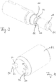
- the clutch assembly 20 a first clutch hub 22, a second clutch hub 24 and a clutch plate 26, which is located in the power flow path between the two clutch hubs 22, 24.
- the first clutch hub 22 is a substantially hollow cylindrical sleeve which has along its inner circumference an axially aligned groove 28 which can be positively engaged with a corresponding spring 29 on the outer periphery of the output shaft 18 of the electric motor (see also Fig. 2 ) so as to connect the first clutch hub 22 torsionally rigid with the output shaft 18 of the electric motor can.
- the second clutch hub 24 is connected to the pump system shaft 16.
- both the first clutch hub 22 and the second clutch hub 24 each have two cams 30 and 32, which are formed on a front-side closed end of the respective clutch hub 22, 24 and projecting therefrom in the axial direction.
- Both the two cams 30 of the first clutch hub 22 and the two cams 32 of the second clutch hub 24 are offset by 180 ° in the circumferential direction to each other.
- the two cams 30 of the first clutch hub 22 have the same distance to the axis of the first clutch hub 22 in the radial direction and also the two cams 32 of the second clutch hub 24 have the same distance from the axis of the second clutch hub 24.
- Both the cams 30 of the first clutch hub 22 and the cams 32 of the second clutch hub 24 have a substantially rectangular cross-section (see in particular FIG Fig. 7 ), which does not change in the axial direction and thus is constant.
- the clutch disc 26 has four recesses 36 of U-shaped configuration, which extend from the peripheral edge of the clutch disc 26 radially inwardly.
- Each of the recesses 36 has two parallel and radially aligned guide surfaces 38, which means that each of the recesses 36 forms a slot 40 which passes through the clutch plate 26.
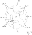
- the slots 40 are each offset by 90 ° in the circumferential direction to each other in the clutch disc 26, so that the cam 30 of the first clutch hub 22 can engage from one side of the clutch plate 25 in two mutually offset by 180 ° in the circumferential direction slots 40 of the clutch disc 26 and in a corresponding manner, the cams 32 of the second clutch hub 24 from the other side of the clutch disc 26 in the other two slots 40 of the clutch disc 26 can engage (see Fig. 7 ).
- the cams 30, 32 each have a substantially rectangular shape in cross-section, with each cam 30, 32 having two lateral guide surfaces 34, which are spaced from each other by the circumferential dimension of the cams 30 and 32, respectively.
- the circumferential dimension of the cams 30, 32 is slightly smaller than the distance between the guide surfaces 38 of the slots 40 of the clutch disc 26, so that the clutch hubs 22, 24 via their cams 30 and 32 with a low mounting clearance with the clutch disc 26 and in particular with whose slots 40 can be paired.
- the clutch disc 26 can thus rotate with relative movement with respect to the two hubs 22, 24 perform, if there is a radial offset between them.
- the cams 30 of the first clutch hub 22 thus form in conjunction with the slots 40 of the clutch disc 26, in which they engage, a first linear guide and also the cams 32 of the second clutch hub 24 in conjunction with the slots 40 of the clutch disc 26, in which they engage, a second linear guide.
- the linear guides thus formed, by means of which the two clutch hubs 22, 24 are rotationally rigidly connected to the clutch disc 26, are oriented perpendicular to each other.
- Fig. 3 can be removed, the cams 30 of the first clutch hub 22 on an axial extension length corresponding to about 70% of the thickness of the clutch plate 26.
- the cams 32 of the second clutch hub 24, however, have a longitudinal extent corresponding to about 95% of the thickness of the clutch disc 26.
- the cams 30 of the first clutch hub 22 thus form, with the cams 32 of the second clutch hub 24 in the axial direction, an overlap length corresponding to about 65% of the thickness of the clutch plate 26, thereby ensuring that the clutch plate 26 is substantially free of transverse force stresses ,
Landscapes
- Engineering & Computer Science (AREA)
- General Engineering & Computer Science (AREA)
- Mechanical Engineering (AREA)
- Applications Or Details Of Rotary Compressors (AREA)
Abstract
Description
- Die vorliegende Erfindung betrifft eine Vakuumpumpe, insbesondere eine Drehschieberpumpe, mit einem Pumpsystem, das von einem Elektromotor angetrieben wird, dessen Abtriebswelle mit einer Antriebswelle des Pumpsystems mittels einer Kupplungsanordnung zur Kompensation eines etwaigen Radialversatzes zwischen den beiden Wellen antriebswirksam verbunden ist.
- Obwohl die einzelnen Komponenten von Vakuumpumpen hochpräzise gearbeitet werden, können beim Zusammenbau derartiger Pumpen gewisse Montagetoleranzen auftreten, die dazu führen können, dass es zu einem Radialversatz zwischen der Abtriebswelle des Antriebsmotors der Pumpe und der von dem Motor angetriebenen Antriebswelle des Pumpsystems der Pumpe kommt. Selbst wenn derartige Montagetoleranzen nur gering sind, kann es insbesondere aufgrund der hohen Drehzahlen im Bereich von etwa 1500 bis 3600 U/min, mit denen derartige Pumpen betrieben werden, zu Materialermüdungserscheinungen kommen, wenn die Abtriebswelle des Elektromotors trotz eines etwaigen Radialversatzes gegenüber der Antriebswelle des Pumpsystems mit dieser unmittelbar drehstarr gekoppelt wird.
- Der Erfindung liegt daher die Aufgabe zugrunde, derartigen Materialermüdungserscheinungen bei einer Vakuumpumpe, die sich aufgrund von Montagetoleranzen ergeben können, zuvor zu kommen.
- Diese Aufgabe wird durch eine Vakuumpumpe mit den Merkmalen des Anspruchs 1 sowie durch eine Kupplungsanordnung mit den Merkmalen des Anspruchs 8 und insbesondere jeweils dadurch gelöst, dass die Kupplungsscheibe der Kupplungsanordnung mittels einer ersten Linearführung mit der ersten Kupplungsnabe drehstarr verbunden ist und mittels einer zweiten Linearführung mit der zweiten Kupplungsnabe drehstarr verbunden ist, wobei die zweite Linearführung lotrecht zu der ersten Linearführung orientiert ist.
- Bei den beiden Linearführungen handelt es sich um Schubgelenke, die eine Linearbewegung der Kupplungsscheibe in radialer Richtung der Wellen der Pumpe ermöglichen, eine Verdrehung zwischen den jeweiligen Kupplungspartnern in Form der Kupplungsnaben und der Kupplungsscheibe jedoch unterbinden. Da jedoch die potentiellen Bewegungsrichtungen der beiden Linearführungen lotrecht zueinander orientiert sind, wird die Kupplungsscheibe unverschieblich zwischen den beiden Kupplungsnaben gehalten, solange sich die Kupplungsanordnung bzw. die Wellen der Pumpe nicht drehen. Wird jedoch über die Kupplungsanordnung eine Drehung der Abtriebswelle des Elektromotors auf die Antriebswelle des Pumpsystems übertragen und liegt ein Radialversatz zwischen den beiden Wellen vor, so wird dieser Radialversatz durch eine Relativbewegung der Kupplungsscheibe ausgeglichen. Insbesondere kommt es hierbei zu einer Art Taumelbewegung der Kupplungsscheibe durch die ein etwaiger Radialversatz zwischen den beiden Wellen ausgeglichen wird. Je nach Drehstellung der Kupplungsscheibe erfährt dieselbe dabei eine momentane Bewegungsrichtung, die sich aus zwei zueinander lotrechten Bewegungskomponenten entsprechend den zueinander lotrechten Linearführung der Kupplungsscheibe zusammensetzt. Je nach Drehwinkel überwiegt hierbei die eine oder die andere Bewegungskomponente, wodurch es in Summe zu der erwähnten Taumelbewegung der Kupplungsscheibe kommt, wenn mittels der Kupplungsanordnung eine Drehung von der Abtriebswelle des Elektromotors auf die Antriebswelle des Pumpsystems übertragen wird.
- Die Kupplungsscheibe gleicht somit infolge ihrer Taumelbewegung einen etwaigen Radialversatz zwischen den beiden Wellen aus, wobei sie zur Drehmomentübertragung zwischen den beiden Wellen mit diesen bzw. den Kupplungsnaben drehstarr über die jeweilige Linearführung verbunden ist. Ein etwaiger Radialversatz zwischen den beiden Wellen wird somit nicht durch Zwangsspannungen in einem Kupplungsbauteil kompensiert; vielmehr wird ein etwaiger Radialversatz kontinuierlich ausgeglichen, indem die Kupplungsscheibe eine durch die beiden Linearführungen definierte Taumelbewegung ausführt, wenn eine Drehbewegung der Abtriebswelle über die Kupplungsscheibe auf die Antriebswelle des Pumpsystems übertragen wird. Die Kupplungsscheibe unterliegt somit keinen Zwängen bzw. Zwangsspannungen, so dass sich keine Materialermüdungserscheinungen ergeben können.
- Im Folgenden wird nun auf bevorzugte Ausführungsformen der Erfindung eingegangen. Weitere Ausführungsformen können sich auch aus den abhängigen Ansprüchen, der Figurenbeschreibung sowie den Zeichnungen ergeben.
- So ist es gemäß einer bevorzugten Ausführungsform vorgesehen, dass die Kupplungsscheibe in axialer Richtung von vier Langlöchern durchsetzt ist, deren Längenerstreckung in radialer Richtung verläuft, wobei die Langlöcher jeweils um 90° in Umfangsrichtung zueinander versetzt sind. Die Kupplungsscheibe ist also auf der 3-, auf der 6-, auf der 9- und auf der 12-Uhr-Position jeweils von einem Langloch durchsetzt, dessen Längenerstreckung jeweils in radialer Richtung verläuft. In zwei dieser Langlöcher, die um 180° in Umfangsrichtung zueinander versetzt sind, also beispielsweise in die Langlöcher auf der 12- und auf der 6-Uhr-Stellung, greifen dabei zwei Nocken ein, die an einem Stirnende der ersten Kupplungsnabe ausgebildet sind. In entsprechender Weise greifen in die beiden anderen Langlöcher, also beispielweise in jene auf der 3- und auf der 9-Uhr-Position, zwei Nocken ein, die an einem Stirnende der zweiten Kupplungsnabe ausgebildet sind. Insofern bilden also zwei miteinander fluchtende Langlöcher der Kupplungsscheibe zusammen mit den in die Langlöcher greifenden Nocken, die von der ersten bzw. von der zweiten Kupplungsnabe abstehen, jeweils eine Linearführung. Hierbei greifen die Nocken der ersten Kupplungsnabe von einer Seite der Kupplungsscheibe in dieselbe bzw. in deren Langlöcher ein, wohingegen die Nocken der zweiten Kupplungsnabe von der anderen Seite der Kupplungsscheibe in dieselbe bzw. in die entsprechenden Langlöcher der Kupplungsscheibe eingreifen. Dies hat zur Folge, dass die Nocken der ersten Kupplungsnabe in axialer Richtung betrachtet zumindest bereichsweise die Nocken der zweiten Kupplungsnabe übergreifen. Ein mittels der Kupplungsscheibe zwischen den beiden Kupplungsnaben zu übertragendes Drehmoment wird somit im Wesentlichen in Form von in der Ebene der Kupplungsscheibe wirkenden Druckkräften zwischen den Nocken der ersten Kupplungsnabe und den Nocken der zweiten Kupplungsnabe übertragen.
- Würden sich hingegen die Nocken der ersten bzw. der zweiten Kupplungsnabe in axialer Richtung nicht übergreifen, würde die Drehmoment- bzw. Kraftübertragung zu einem nicht unwesentlichen Anteil über Schubspannungen in der Kupplungsscheibe erfolgen, die zu einer nicht unerheblichen Verformung derselben führen können, sofern die Kupplungsscheibe nicht entsprechend massiv ausgebildet wird. Derartige Schubspannungen in der Kupplungsscheibe können aufgrund der erfindungsgemäßen Ausbildung derselben sowie der sich in axialer Richtung übergreifenden Nocken der beiden Kupplungsnaben weitestgehend vermieden werden, so dass die Kupplungsscheibe verhältnismäßig filigran ausgebildet werden kann, da sie im Wesentlichen nur auf Druck in Umfangsrichtung beansprucht wird.
- Gemäß einer weiteren Ausführungsform kann jedes der Langlöcher eine in sich geschlossene Berandung aufweisen, die durch die Kupplungsscheibe gebildet wird. Gemäß einer anderen Ausführungsform kann jedes der Langlöcher eine offene Berandung aufweisen, die in einen Umfangsrand der Kupplungsscheibe übergeht. Besitzen also die Langlöcher eine geschlossene Berandung, so weisen die Langlöcher gewissermaßen im Wesentlichen die Gestalt einer "0" auf, wohingegen die Langlöcher gewissermaßen im Wesentlichen die Gestalt eines "U" aufweisen, wenn sie eine offene Berandung besitzen, die in einen Umfangsrand der Kupplungsscheibe übergeht.
- Um sicherzustellen, dass Drehmomente zwischen den beiden Kupplungsnaben im Wesentlichen ausschließlich über in der Ebene der Kupplungsscheibe wirkende Druckkräfte übertragen werden, kann es gemäß einer weiteren Ausführungsform vorgesehen sein, dass sich die am Stirnende der ersten Kupplungsnabe und der zweiten Kupplungsnabe ausgebildeten Nocken in Axialrichtung über mehr als 70 %, vorzugsweise mehr als 85 % und insbesondere vorzugsweise mehr als 95 % der Dicke der Kupplungsscheibe in die jeweiligen Langlöcher hinein erstrecken. Die am Stirnende der ersten Kupplungsnabe ausgebildeten Nocken bilden somit mit den am Stirnende der zweiten Kupplungsnabe ausgebildeten Nocken in axialer Richtung betrachtet eine Übergreifungslänge, die größer als 40 %, vorzugsweise größer als 70 % und insbesondere größer als 90 % der Dicke der Kupplungsscheibe ist. Mit zunehmender Übergreifungslänge werden hierbei etwaige Scher- bzw. Querkraftbeanspruchungen der Kupplungsscheibe reduziert. Die Kupplungsscheibe kann somit verhältnismäßig filigran ausgeführt werden, da mit zunehmender Übergreifungslänge der Nocken der beiden Kupplungsnaben die Querkraftbeanspruchung der Kupplungsnabe reduziert wird.
- Gemäß einer weiteren Ausführungsform kann die Kupplungsscheibe aus Stahl gefertigt sein, vorzugsweise aus Vergütungsstahl. Die Kupplungsscheibe ist somit auch bei geringeren Übergreifungslängen der Nocken der beiden Kupplungsnaben formstabil. Selbst wenn die Kupplungsscheibe also hohen mechanischen Beanspruchungen ausgesetzt ist, erhält sie somit ihre Form bei, um in der gewünschten Weise die zuvor beschriebene Taumelbewegung zwischen den Kupplungsnaben zum Ausgleich eines etwaigen Wellenversatzes durchführen zu können.
- Wie aus den vorausstehenden Erläuterungen ersichtlich wird, kommt es aufgrund der Taumelbewegung der Kupplungsscheibe während des Betriebs der Pumpe zu Relativbewegungen zwischen den Kupplungspartnern und damit zu oszillierenden Gleitbewegungen zwischen der Kupplungsscheibe und den beiden Kupplungsnaben, wobei diese Gleitbewegungen wiederum oszillierende Auflagerkräfte zwischen den Kupplungspartnern hervorrufen. Somit kann es zu unerwünschten Verschleißerscheinungen der Kupplungspartner kommen. Ferner kann es bei einer Lastumkehr des Kupplungsstrangs zu einem Abheben und umseitigen Anschlagen der Kontaktflächen zwischen den Kupplungspartnern kommen, was in unerwünschter Weise ein Klappergeräusch hervorrufen kann. Um diesen Erscheinungen entgegenzuwirken, kann es erfindungsgemäß vorgesehen sein, dass die Oberflächen der Kupplungspartner und/oder die Materialien, aus denen die Kupplungspartner gefertigt sind, hinsichtlich ihrer Gleit- und Festigkeitseigenschaften optimal gewählt bzw. optimiert werden.
- Dementsprechend kann es gemäß einer Ausführungsform vorgesehen sein, dass zumindest die Kontaktflächen mindestens eines Kupplungspartners eine Beschichtung aufweisen, die sich vorzugsweise durch einen geringen Reibkoeffizienten auszeichnet. Wird nicht nur ein Kupplungspartner bzw. dessen Kontaktflächen beschichtet, können zwar grundsätzlich ähnliche Beschichtungswerkstoffe für die jeweiligen Kupplungspartner zum Einsatz kommen. Beispielsweise können die Beschichtungswerkstoffe der jeweiligen Kupplungspartner derselben Stofffamilie wie zum Beispiel Metall, Kunststoff oder Keramik angehören. Vorteilhafterweise sollten sich die Beschichtungswerkstoffe der jeweiligen Kupplungspartner jedoch zumindest hinsichtlich der Legierung und/oder Herstellungsart voneinander unterscheiden. Zusätzlich oder alternativ kann es vorgesehen sein, dass die jeweiligen Kupplungspartner Beschichtungen mit selbstschmierenden Eigenschaften aufweisen, wie zum Beispiel PTFE als hoch belastbarer, gleitfähiger Kunststoff, Sinterbronze mit infiltriertem Dauerschmiermittel oder Gusseisen mit legierungsabhängigen Graphitanteilen.
- Anstatt die jeweiligen Kupplungspartner in der zuvor erläuterten Weise mit den erwähnten Beschichtungswerkstoffe zu beschichten, kann es gemäß einer weiteren Ausführungsform vorgesehen sein, die jeweiligen Kupplungspartner als Vollkörper aus den erwähnten Werkstoffen zu fertigen. So kann es gemäß einer Ausführungsform vorgesehen sein, dass zumindest ein Kupplungspartners aus einem Werkstoff besteht, der sich vorzugsweise durch einen geringen Reibkoeffizienten auszeichnet. Zwar können grundsätzlich ähnliche Werkstoffe für die jeweiligen Kupplungspartner zum Einsatz kommen. Beispielsweise können die Werkstoffe der jeweiligen Kupplungspartner derselben Stofffamilie wie zum Beispiel Metall, Kunststoff, oder Keramik angehören. Vorteilhafterweise sollten sich die Werkstoffe der jeweiligen Kupplungspartner jedoch zumindest hinsichtlich der Legierung und/oder Herstellungsart voneinander unterscheiden. Zusätzlich oder alternativ kann es vorgesehen sein, dass die Werkstoffe der jeweiligen Kupplungspartner selbstschmierende Eigenschaften aufweisen, wie zum Beispiel PTFE als hoch belastbarer, gleitfähiger Kunststoff, Sinterbronze mit infiltriertem Dauerschmiermittel oder Gusseisen mit legierungsabhängigen Graphitanteilen.
- Gemäß einer derzeit bevorzugten Ausführungsform ist es vorgesehen, dass als Werkstoffe, aus denen die Kupplungspartner bestehen, und/oder als Beschichtungswerkstoff für die Kupplungspartner folgende Werkstoffe zum Einsatz kommen können: für die zweite Kupplungsnabe Grauguss, bspw. GGG-40, und für die erste Kupplungsnabe sowie für die Kupplungsscheibe zwei ähnliche, aber hinreichend unterschiedliche Einsatzstähle. So kann beispielweise für die erste Kupplungsnabe 16MnCr5-Einsatzstahl und für die Kupplungsscheibe 42CrMo4+QT-Einsatzstahl zum Einsatz kommen.
- Gemäß weiteren Ausführungsformen können auch folgende Werkstoffe als Beschichtung oder als Vollmaterial für die jeweiligen Kupplungspartner zum Einsatz kommen:
- Gusseisen, beispielsweise Grauguss (GJL bzw. GGL), insbesondere GG-15, GG-25, GG-35; Temperguss (GJMW oder GJMB); oder Gusseisen mit Kugelgraphit (GJS), insbesondere GGG-40, GGG-60 oder GGG-80;
- Vergütungsstahl, beispielsweise C45, C60, 42CrMo4 oder 34CrNiMo6; und
- Einsatzstahl, beispielsweise C10E, 16MnCr5 oder 18CrNiMo7-6.
- Gemäß noch einer weiteren Ausführungsform können die Nocken und die Langlöcher einen in axialer Richtung gleichbleibenden bzw. konstanten Querschnitt aufweisen. Hierdurch wird nicht nur die Montage der erfindungsgemäßen Kupplungsanordnung erleichtert, da die einzelnen Bauteile der Kupplungsanordnung in axialer Richtung einfach zusammengesteckt werden können; durch den in axialer Richtung gleichbleibenden Querschnitt der Nocken und der Langlöcher werden jedoch auch die Spannungen zwischen den Nocken und den Berandungen der Langlöcher reduziert, da aufgrund der in axialer Richtung gleichbleibenden Querschnittsflächen der Nocken und der Langlöcher die Nocken über ihre gesamte axiale Länge hinweg mit den jeweiligen Berandungen der Langlöcher in Kontakt stehen, wodurch der Krafteinleitungsbereich zugunsten einer Reduzierung der Spannungen maximiert wird.
- Im Folgenden wird die Erfindung nun rein exemplarisch unter Bezugnahme auf die Zeichnungen beschrieben, in denen:
- Fig. 1
- eine Schnittdarstellung durch eine erfindungsgemäße Vakuumpumpe zeigt;
- Fig. 2
- eine vergrößerte Darstellung des Details "X" der
Fig. 1 im Bereich der Kupplungsanordnung zeigt; - Fig. 3
- eine perspektivische Darstellung einer erfindungsgemäßen Kupplungsanordnung zeigt;
- Fig. 4
- eine perspektivische Darstellung einer ersten Kupplungsnabe zeigt;
- Fig. 5
- eine perspektivische Darstellung einer Pumpsystemwelle mit einer drehstar daran angebrachten zweiten Kupplungsnabe zeigt;
- Fig. 6
- eine perspektivische Darstellung einer Kupplungsscheibe zeigt; und
- Fig. 7
- eine Querschnittsdarstellung durch die Kupplungsanordnung der
Fig. 3 im Bereich der Kupplungsscheibe zeigt. - Die
Fig. 1 veranschaulicht eine erfindungsgemäße Vakuumpumpe 10, bei der es sich hier um eine Drehschieberpumpe 10 handelt. Die Pumpe 10 umfasst ein Pumpsystemgehäuse 12, welches an ein Motorgehäuse 14 zur Aufnahme eines nicht dargestellten Elektromotors angebaut ist. Das Pumpsystemgehäuse 12 enthält ein hier nur schematisch dargestelltes Pumpsystem, welches von einem in dem Elektromotorgehäuse 14 untergebrachten Elektromotor (nicht dargestellt) angetrieben wird. Insbesondere weist das Pumpsystem eine Pumpsystemwelle 16 auf, welche von der Abtriebswelle 18 des Elektromotors, von der hier nur ein Keilwellenabschnitt 19 erkennbar ist (siehe vor allemFig. 2 ), angetrieben wird und insofern eine Antriebswelle 16 darstellt. Da die Pumpsystem- bzw. Antriebswelle 16 des Pumpsystems aufgrund von Montagetoleranzen einen Radialversatz gegenüber der Abtriebswelle 18 aufweisen kann, sind die beiden Wellen 16, 18 mittels einer erfindungsgemäßen Kupplungsanordnung 20 antriebswirksam verbunden. Diese Kupplungsanordnung 20 wird nachfolgend unter Bezugnahme auf dieFig. 3 bis 7 im Detail beschrieben. - Wie der
Fig. 3 entnommen werden kann, weist die Kupplungsanordnung 20 eine erste Kupplungsnabe 22, eine zweite Kupplungsnabe 24 sowie eine Kupplungsscheibe 26 auf, die sich im Kraftflusspfad zwischen den beiden Kupplungsnaben 22, 24 befindet. Bei der ersten Kupplungsnabe 22 handelt es sich um eine im Wesentlichen hohlzylindrische Buchse, die entlang ihres Innenumfangs eine axial ausgerichtete Nut 28 aufweist, die mit einer entsprechenden Feder 29 am Außenumfang der Abtriebswelle 18 des Elektromotors formschlüssig in Eingriff gebracht werden kann (siehe auchFig. 2 ), um so die erste Kupplungsnabe 22 drehstarr mit der Abtriebswelle 18 des Elektromotors verbinden zu können. In entsprechender Weise ist die zweite Kupplungsnabe 24 mit der Pumpsystemswelle 16 verbunden. - Wie den
Fig. 4 und5 entnommen werden kann, weisen sowohl die erste Kupplungsnabe 22 als auch die zweite Kupplungsnabe 24 jeweils zwei Nocken 30 bzw. 32 auf, welche an einem stirnseitigen geschlossenen Ende der jeweiligen Kupplungsnabe 22, 24 ausgebildet sind und von diesem in axialer Richtung abstehen. Sowohl die beiden Nocken 30 der ersten Kupplungsnabe 22 als auch die beiden Nocken 32 der zweiten Kupplungsnabe 24 sind dabei um 180° in Umfangsrichtung zueinander versetzt. Die beiden Nocken 30 der ersten Kupplungsnabe 22 weisen dabei in radialer Richtung denselben Abstand zur Achse der ersten Kupplungsnabe 22 auf und auch die beiden Nocken 32 der zweiten Kupplungsnabe 24 weisen denselben Abstand zur Achse der zweiten Kupplungsnabe 24 auf. Sowohl die Nocken 30 der ersten Kupplungsnabe 22 als auch die Nocken 32 der zweiten Kupplungsnabe 24 weisen einen im Wesentlichen rechteckigen Querschnitt auf (siehe insbesondereFig. 7 ), der sich in axialer Richtung nicht verändert und somit konstant ist. - Wie am besten der Zusammenschau der
Fig. 6 und7 entnommen werden kann, weist die Kupplungsscheibe 26 vier Ausnehmungen 36 mit U-förmiger Gestalt auf, welche sich vom Umfangsrand der Kupplungsscheibe 26 radial nach innen erstrecken. Jede der Ausnehmungen 36 weist zwei parallele und radial ausgerichtete Führungsflächen 38 auf, was bedeutet, dass jede der Ausnehmungen 36 ein Langloch 40 bildet, welches die Kupplungsscheibe 26 durchsetzt. - Die Langlöcher 40 sind dabei jeweils um 90° in Umfangsrichtung versetzt zueinander in der Kupplungsscheibe 26 ausgebildet, so dass die Nocken 30 der ersten Kupplungsnabe 22 von einer Seite der Kupplungsscheibe 25 in zwei um 180° in Umfangsrichtung zueinander versetzte Langlöcher 40 der Kupplungsscheibe 26 eingreifen können und in entsprechender Weise die Nocken 32 der zweiten Kupplungsnabe 24 von der anderen Seite der Kupplungsscheibe 26 in die beiden anderen Langlöcher 40 der Kupplungsscheibe 26 eingreifen können (siehe
Fig. 7 ). - Wie bereits erwähnt, weisen die Nocken 30, 32 im Querschnitt jeweils eine im Wesentlichen rechteckige Gestalt auf, wobei jeder Nocken 30, 32 zwei seitliche Führungsflächen 34 aufweist, die durch die Umfangsabmessung der Nocken 30 bzw. 32 voneinander beabstandet sind. Die Umfangsabmessung der Nocken 30, 32 ist dabei geringfügig kleiner als der Abstand zwischen den Führungsflächen 38 der Langlöcher 40 der Kupplungsscheibe 26, so dass die Kupplungsnaben 22, 24 über ihre Nocken 30 bzw. 32 mit einem geringen Montagespiel mit der Kupplungsscheibe 26 und insbesondere mit deren Langlöchern 40 gepaart werden kann. Die Kupplungsscheibe 26 kann somit unter Drehung eine Relativbewegung bezüglich der beiden Naben 22, 24 ausführen, sofern zwischen diesen ein Radialversatz vorliegt. Die Nocken 30 der ersten Kupplungsnabe 22 bilden somit in Verbindung mit den Langlöchern 40 der Kupplungsscheibe 26, in die sie eingreifen, eine erste Linearführung und auch die Nocken 32 der zweiten Kupplungsnabe 24 bilden in Verbindung mit den Langlöchern 40 der Kupplungsscheibe 26, in die sie eingreifen, eine zweite Linearführung. Die so gebildeten Linearführungen, mittels derer die beiden Kupplungsnaben 22, 24 mit der Kupplungsscheibe 26 drehstarr verbunden sind, sind dabei lotrecht zueinander orientiert. Wenn daher eine Drehbewegung der Motorabtriebswelle 18 über die Kupplungsanordnung 20 auf die Antriebswelle 16 übertragen wird, wird ein etwaiger Versatz der beiden Wellen 16, 18 durch eine Taumelbewegung der Kupplungsscheibe 26 ausgeglichen, wobei sich die Bewegung der Kupplungsscheibe 26 je nach Drehstellung der Wellen 16, 18 aus zwei Bewegungskomponenten zusammensetzt, die durch die Linearführungen vorgegeben sind.
- Wie der
Fig. 3 entnommen werden kann, weisen die Nocken 30 der ersten Kupplungsnabe 22 eine axiale Erstreckungslänge auf, die etwa 70 % der Dicke der Kupplungsscheibe 26 entspricht. Die Nocken 32 der zweiten Kupplungsnabe 24 weisen hingegen eine Längenerstreckung auf, die etwa 95 % der Dicke der Kupplungsscheibe 26 entspricht. Die Nocken 30 der ersten Kupplungsnabe 22 bilden somit mit den Nocken 32 der zweiten Kupplungsnabe 24 in axialer Richtung betrachtet eine Übergreifungslänge, die etwa 65 % der Dicke der Kupplungsscheibe 26 entspricht, wodurch sichergestellt werden kann, dass die Kupplungsscheibe 26 im Wesentlichen frei von Querkraftbeanspruchungen ist. -
- 10
- Drehschieberpumpe
- 12
- Pumpsystemgehäuse
- 14
- Elektromotorgehäuse
- 16
- Pumpsystemwelle
- 18
- Abtriebswelle des Elektromotors
- 19
- Keilwellenabschnitt
- 20
- Kupplungsanordnung
- 22
- erste Kupplungsnabe
- 24
- zweite Kupplungsnabe
- 26
- Kupplungsscheibe
- 28
- Nut
- 29
- Feder
- 30
- Nocken von 22
- 32
- Nocken von 24
- 34
- Führungsfläche von 30 bzw. 32
- 36
- Ausnehmungen in 26
- 38
- Führungsflächen von 36
- 40
- Langlöcher durch 26
Claims (14)
- Vakuumpumpe, insbesondere Drehschieberpumpe (10), mit einem Pumpsystem, das von einem Elektromotor angetrieben wird, wozu der Elektromotor eine Abtriebswelle (18) aufweist, die mit einer Antriebswelle (16) des Pumpsystems mittels einer Kupplungsanordnung (20) antriebswirksam verbunden ist, wobei die Kupplungsanordnung (20) umfasst:- eine erste Kupplungsnabe (22), die drehstarr mit der Abtriebswelle (18) des Elektromotors verbunden ist;- eine zweite Kupplungsnabe (24), die drehstarr mit der Antriebswelle (16) des Pumpsystem verbunden ist; und- eine Kupplungsscheibe (26) im Kraftflusspfad zwischen der Abtriebswelle (18) und der Antriebswelle (16);wobei die Kupplungsscheibe (26) mittels einer ersten Linearführung mit der ersten Kupplungsnabe (22) drehstarr verbunden ist und mittels einer zweiten Linearführung mit der zweiten Kupplungsnabe (24) drehstarr verbunden ist, wobei die zweite Linearführung lotrecht zu der ersten Linearführung orientiert ist.
- Vorrichtung nach Anspruch 1,
dadurch gekennzeichnet, dass
die Kupplungsscheibe (26) von vier Langlöchern (40) durchsetzt ist, deren Längenerstreckung jeweils in radialer Richtung verläuft, wobei die Langlöcher (40) jeweils um 90° in Umfangsrichtung zueinander versetzt sind,
wobei an einem Stirnende der ersten Kupplungsnabe (22) zwei Nocken (30) ausbildet sind, die in zwei Langlöcher (40) der Kupplungsscheibe (26) eingreifen, die um 180° in Umfangsrichtung zueinander versetzt sind, und wobei an einem Stirnende der zweiten Kupplungsnabe (24) ebenfalls zwei Nocken (32) ausbildet sind, die in jene zwei Langlöcher (40) der Kupplungsscheibe (26) eingreifen, in die die am Stirnende der ersten Kupplungsnabe (22) ausbildeten Nocken (30) nicht eingreifen. - Vorrichtung nach Anspruch 2,
dadurch gekennzeichnet, dass
ein jedes der Langlöcher (40) eine in sich geschlossenen Berandung aufweist, die durch die Kupplungsscheibe (26) gebildet wird; oder
ein jedes der Langlöcher (40) eine offene Berandung aufweist, die in einen Umfangsrand der Kupplungsscheibe (26) übergeht. - Vorrichtung nach Anspruch 2 oder 3,
dadurch gekennzeichnet, dass
die am Stirnende der ersten Kupplungsnabe (22) und der zweiten Kupplungsnabe (24) ausbildeten Nocken (30, 32) sich in axialer Richtung über mehr als 70%, vorzugsweise mehr als 85%, und insbesondere vorzugsweise mehr als 95% der Dicke der Kupplungsscheibe (26) in die jeweiligen Langlöcher (40) hineinerstrecken. - Vorrichtung nach zumindest einem der Ansprüche 2, 3 oder 4,
dadurch gekennzeichnet, dass
die am Stirnende der ersten Kupplungsnabe (22) ausbildeten Nocken (30) mit den am Stirnende der zweiten Kupplungsnabe (24) ausbildeten Nocken (32) eine Übergreifungslänge bilden, die größer als 40%, vorzugsweise größer als 70% und insbesondere größer als 90% der Dicke der Kupplungsscheibe (26) ist. - Vorrichtung nach zumindest einem der vorstehenden Ansprüche,
dadurch gekennzeichnet, dass
die Kupplungsscheibe (26) aus Stahl gefertigt ist, vorzugsweise aus Vergütungsstahl. - Vorrichtung nach zumindest einem der Ansprüche 2 bis 6,
dadurch gekennzeichnet, dass
die Nocken (30, 32) und die Langlöcher (40) einen in axialer Richtung gleichbleibenden Querschnitt aufweisen. - Kupplungsanordnung (20) für eine Vakuumpumpe, insbesondere eine Drehschieberpumpe (10), mit einem Pumpsystem, das von einem Elektromotor angetrieben wird, zum Koppeln einer Abtriebswelle (18) des Elektromotors mit einer Antriebswelle (16) des Pumpsystems, umfassend:- eine erste Kupplungsnabe (22), die drehstarr mit der Abtriebswelle (18) des Elektromotors verbindbar ist;- eine zweite Kupplungsnabe (24), die drehstarr mit der Antriebswelle (16) des Pumpsystem verbindbar ist; und- eine Kupplungsscheibe (26);wobei die Kupplungsscheibe (26) mittels einer ersten Linearführung mit der ersten Kupplungsnabe (22) drehstarr verbunden ist und mittels einer zweiten Linearführung mit der zweiten Kupplungsnabe (24) drehstarr verbunden ist, wobei die zweite Linearführung lotrecht zu der ersten Linearführung orientiert ist.
- Kupplungsanordnung nach Anspruch 8,
dadurch gekennzeichnet, dass
die Kupplungsscheibe (26) von vier Langlöchern (40) durchsetzt ist, deren Längenerstreckung in radialer Richtung verläuft, wobei die Langlöcher (40) jeweils um 90° in Umfangsrichtung zueinander versetzt sind,
wobei an einem Stirnende der ersten Kupplungsnabe (22) zwei Nocken (30) ausbildet sind, die in zwei Langlöcher (40) der Kupplungsscheibe (26) eingreifen, die um 180° in Umfangsrichtung zueinander versetzt sind, und wobei an einem Stirnende der zweiten Kupplungsnabe (24) ebenfalls zwei Nocken (32) ausbildet sind, die in jene zwei Langlöcher (40) der Kupplungsscheibe (26) eingreifen, in die die am Stirnende der ersten Kupplungsnabe (22) ausbildeten Nocken (30) nicht eingreifen. - Kupplungsanordnung nach Anspruch 9,
dadurch gekennzeichnet, dass
ein jedes der Langlöcher (40) eine in sich geschlossenen Berandung aufweist, die durch die Kupplungsscheibe (26) gebildet wird; oder
ein jedes der Langlöcher (40) eine offene Berandung aufweist, die in einen Umfangsrand der Kupplungsscheibe (26) übergeht. - Kupplungsanordnung nach Anspruch 9 oder 10,
dadurch gekennzeichnet, dass
die am Stirnende der ersten Kupplungsnabe (22) und der zweiten Kupplungsnabe (24) ausbildeten Nocken (30, 32) sich in axialer Richtung über mehr als 70%, vorzugsweise mehr als 85%, und insbesondere vorzugsweise mehr als 95% der Dicke der Kupplungsscheibe (26) in die jeweiligen Langlöcher (40) hineinerstrecken. - Kupplungsanordnung nach zumindest einem der Ansprüche 9, 10 oder 11,
dadurch gekennzeichnet, dass
die am Stirnende der ersten Kupplungsnabe (22) ausbildeten Nocken (30) mit den am Stirnende der zweiten Kupplungsnabe (24) ausbildeten Nocken (32) eine Übergreifungslänge bilden, die größer als 40%, vorzugsweise größer als 70% und insbesondere größer als 90% der Dicke der Kupplungsscheibe (26) ist. - Kupplungsanordnung nach zumindest einem der Ansprüche 8 bis 12,
dadurch gekennzeichnet, dass
die Kupplungsscheibe (26) aus Stahl gefertigt ist, vorzugsweise aus Vergütungsstahl. - Kupplungsanordnung nach zumindest einem der Ansprüche 8 bis 13,
dadurch gekennzeichnet, dass
die Nocken (30, 32) und die Langlöcher (40) einen in axialer Richtung gleichbleibenden Querschnitt aufweisen.
Priority Applications (2)
| Application Number | Priority Date | Filing Date | Title |
|---|---|---|---|
| EP16202237.0A EP3330483B1 (de) | 2016-12-05 | 2016-12-05 | Vakuumpumpe mit einer kupplungsanordnung zur kompensation von wellenexzentrizitäten |
| JP2017218206A JP2018091330A (ja) | 2016-12-05 | 2017-11-13 | 軸偏心の補償の為の連結装置を有する真空ポンプ |
Applications Claiming Priority (1)
| Application Number | Priority Date | Filing Date | Title |
|---|---|---|---|
| EP16202237.0A EP3330483B1 (de) | 2016-12-05 | 2016-12-05 | Vakuumpumpe mit einer kupplungsanordnung zur kompensation von wellenexzentrizitäten |
Publications (2)
| Publication Number | Publication Date |
|---|---|
| EP3330483A1 true EP3330483A1 (de) | 2018-06-06 |
| EP3330483B1 EP3330483B1 (de) | 2021-02-03 |
Family
ID=57485382
Family Applications (1)
| Application Number | Title | Priority Date | Filing Date |
|---|---|---|---|
| EP16202237.0A Active EP3330483B1 (de) | 2016-12-05 | 2016-12-05 | Vakuumpumpe mit einer kupplungsanordnung zur kompensation von wellenexzentrizitäten |
Country Status (2)
| Country | Link |
|---|---|
| EP (1) | EP3330483B1 (de) |
| JP (1) | JP2018091330A (de) |
Cited By (1)
| Publication number | Priority date | Publication date | Assignee | Title |
|---|---|---|---|---|
| CN113983078A (zh) * | 2021-10-14 | 2022-01-28 | 宁波斯达弗液压传动有限公司 | 一种可在狭窄空间内使用的全金属联轴器 |
Citations (7)
| Publication number | Priority date | Publication date | Assignee | Title |
|---|---|---|---|---|
| DE250016C (de) * | ||||
| US1316011A (en) * | 1919-09-16 | bailey and g | ||
| DE6752034U (de) * | 1967-10-24 | 1969-02-27 | Contraves Ag | Kreuzkupplung |
| DE1600198A1 (de) * | 1966-11-11 | 1970-05-06 | Ind Karl Marx Stadt Veb | Kreuzgelenkkupplung |
| DE3805346A1 (de) * | 1987-04-04 | 1988-10-20 | Barmag Barmer Maschf | Fluegelzellenpumpe |
| EP2963240A2 (de) * | 2014-07-04 | 2016-01-06 | Pfeiffer Vacuum Gmbh | Vakuumpumpe |
| EP3029326A1 (de) * | 2013-10-07 | 2016-06-08 | Sanoh Industrial Co., Ltd. | Unterdruckpumpe und zylinderkopfhaube |
Family Cites Families (3)
| Publication number | Priority date | Publication date | Assignee | Title |
|---|---|---|---|---|
| US1413117A (en) * | 1921-07-09 | 1922-04-18 | Higgins Eugene | Shaft coupling |
| JPH03239843A (ja) * | 1990-02-19 | 1991-10-25 | Sumitomo Heavy Ind Ltd | 内接噛合遊星歯車構造 |
| JPH05180236A (ja) * | 1991-12-27 | 1993-07-20 | Kayseven Co Ltd | 軸継手 |
-
2016
- 2016-12-05 EP EP16202237.0A patent/EP3330483B1/de active Active
-
2017
- 2017-11-13 JP JP2017218206A patent/JP2018091330A/ja active Pending
Patent Citations (7)
| Publication number | Priority date | Publication date | Assignee | Title |
|---|---|---|---|---|
| DE250016C (de) * | ||||
| US1316011A (en) * | 1919-09-16 | bailey and g | ||
| DE1600198A1 (de) * | 1966-11-11 | 1970-05-06 | Ind Karl Marx Stadt Veb | Kreuzgelenkkupplung |
| DE6752034U (de) * | 1967-10-24 | 1969-02-27 | Contraves Ag | Kreuzkupplung |
| DE3805346A1 (de) * | 1987-04-04 | 1988-10-20 | Barmag Barmer Maschf | Fluegelzellenpumpe |
| EP3029326A1 (de) * | 2013-10-07 | 2016-06-08 | Sanoh Industrial Co., Ltd. | Unterdruckpumpe und zylinderkopfhaube |
| EP2963240A2 (de) * | 2014-07-04 | 2016-01-06 | Pfeiffer Vacuum Gmbh | Vakuumpumpe |
Cited By (1)
| Publication number | Priority date | Publication date | Assignee | Title |
|---|---|---|---|---|
| CN113983078A (zh) * | 2021-10-14 | 2022-01-28 | 宁波斯达弗液压传动有限公司 | 一种可在狭窄空间内使用的全金属联轴器 |
Also Published As
| Publication number | Publication date |
|---|---|
| EP3330483B1 (de) | 2021-02-03 |
| JP2018091330A (ja) | 2018-06-14 |
Similar Documents
| Publication | Publication Date | Title |
|---|---|---|
| DE102017111668B4 (de) | Lagerbuchse | |
| WO2017041802A1 (de) | Getriebe mit elastischem zahnrad | |
| DE102013207665A1 (de) | Spindelgetriebe für eine Verstellvorrichtung in einem Kraftfahrzeug sowie Fahrzeugsitz | |
| DE102007051475A1 (de) | Verbindung eines Achsversatzausgleichselements und eines Innenrings eines Wälzlagers | |
| DE102009036986B4 (de) | Ausgleichsgetriebe | |
| DE102008053915B4 (de) | Spannungswellengetriebe und Vorrichtung zum Überlagern von Bewegungen | |
| DE102004008538B4 (de) | Differential mit einer Bolzenbefestigungsbaugruppe | |
| DE102006010270B4 (de) | Zahnradanordnung | |
| DE102007055838A1 (de) | Wellgetriebevorrichtung mit einem vereinfachten Aufbau | |
| DE102004041751B4 (de) | Nockenwellenversteller mit einer Kupplung zwischen einer Stellwelle und einem Verstellgetriebe | |
| EP1840410A2 (de) | Zahnrad | |
| DE202017106652U1 (de) | Zweistufiges Getriebe für einen Verstellantrieb sowie Verstellantrieb für einen Kraftfahrzeugsitz | |
| DE102016222897B4 (de) | Kupplungsvorrichtung sowie Wellgetriebe mit der Kupplungsvorrichtung | |
| DE102016218412A1 (de) | Schwenkhebelanordnung für eine Scheibenbremse mit Flügelabschnitten | |
| DE202009009806U1 (de) | Förderwalze mit verbesserter Laufruhe | |
| EP3330483B1 (de) | Vakuumpumpe mit einer kupplungsanordnung zur kompensation von wellenexzentrizitäten | |
| EP0224876A2 (de) | Anordnung mit Wälzelementen | |
| EP1738088A1 (de) | Kraftübertragungsaggregat mit gewelltem sicherungsring | |
| DE102014014430B4 (de) | Wellenkupplung zum drehmomentübertragenden Verbinden von zwei Wellen unter Ausgleich eines eventuellen Achsversatzes der beiden Wellen | |
| DE102014203206A1 (de) | Genietete Radlagereinheit mit verbesserter Klemmkraft | |
| DE102016220854B4 (de) | Verstellvorrichtung | |
| DE102010064053A1 (de) | Exzenterantrieb für mindestens einen kolben einer Kolbenpumpe | |
| DE102016207927A1 (de) | Stellantrieb | |
| DE102014210349A1 (de) | Betätigungseinrichtung | |
| DE102014210361A1 (de) | Nockenwellenversteller |
Legal Events
| Date | Code | Title | Description |
|---|---|---|---|
| PUAI | Public reference made under article 153(3) epc to a published international application that has entered the european phase |
Free format text: ORIGINAL CODE: 0009012 |
|
| STAA | Information on the status of an ep patent application or granted ep patent |
Free format text: STATUS: REQUEST FOR EXAMINATION WAS MADE |
|
| 17P | Request for examination filed |
Effective date: 20170918 |
|
| AK | Designated contracting states |
Kind code of ref document: A1 Designated state(s): AL AT BE BG CH CY CZ DE DK EE ES FI FR GB GR HR HU IE IS IT LI LT LU LV MC MK MT NL NO PL PT RO RS SE SI SK SM TR |
|
| AX | Request for extension of the european patent |
Extension state: BA ME |
|
| STAA | Information on the status of an ep patent application or granted ep patent |
Free format text: STATUS: EXAMINATION IS IN PROGRESS |
|
| 17Q | First examination report despatched |
Effective date: 20200127 |
|
| GRAP | Despatch of communication of intention to grant a patent |
Free format text: ORIGINAL CODE: EPIDOSNIGR1 |
|
| STAA | Information on the status of an ep patent application or granted ep patent |
Free format text: STATUS: GRANT OF PATENT IS INTENDED |
|
| INTG | Intention to grant announced |
Effective date: 20200918 |
|
| GRAS | Grant fee paid |
Free format text: ORIGINAL CODE: EPIDOSNIGR3 |
|
| GRAA | (expected) grant |
Free format text: ORIGINAL CODE: 0009210 |
|
| STAA | Information on the status of an ep patent application or granted ep patent |
Free format text: STATUS: THE PATENT HAS BEEN GRANTED |
|
| AK | Designated contracting states |
Kind code of ref document: B1 Designated state(s): AL AT BE BG CH CY CZ DE DK EE ES FI FR GB GR HR HU IE IS IT LI LT LU LV MC MK MT NL NO PL PT RO RS SE SI SK SM TR |
|
| REG | Reference to a national code |
Ref country code: GB Ref legal event code: FG4D Free format text: NOT ENGLISH |
|
| REG | Reference to a national code |
Ref country code: AT Ref legal event code: REF Ref document number: 1359739 Country of ref document: AT Kind code of ref document: T Effective date: 20210215 Ref country code: CH Ref legal event code: EP |
|
| REG | Reference to a national code |
Ref country code: DE Ref legal event code: R096 Ref document number: 502016012330 Country of ref document: DE |
|
| REG | Reference to a national code |
Ref country code: IE Ref legal event code: FG4D Free format text: LANGUAGE OF EP DOCUMENT: GERMAN |
|
| REG | Reference to a national code |
Ref country code: NL Ref legal event code: MP Effective date: 20210203 |
|
| REG | Reference to a national code |
Ref country code: LT Ref legal event code: MG9D |
|
| PG25 | Lapsed in a contracting state [announced via postgrant information from national office to epo] |
Ref country code: GR Free format text: LAPSE BECAUSE OF FAILURE TO SUBMIT A TRANSLATION OF THE DESCRIPTION OR TO PAY THE FEE WITHIN THE PRESCRIBED TIME-LIMIT Effective date: 20210504 Ref country code: FI Free format text: LAPSE BECAUSE OF FAILURE TO SUBMIT A TRANSLATION OF THE DESCRIPTION OR TO PAY THE FEE WITHIN THE PRESCRIBED TIME-LIMIT Effective date: 20210203 Ref country code: HR Free format text: LAPSE BECAUSE OF FAILURE TO SUBMIT A TRANSLATION OF THE DESCRIPTION OR TO PAY THE FEE WITHIN THE PRESCRIBED TIME-LIMIT Effective date: 20210203 Ref country code: PT Free format text: LAPSE BECAUSE OF FAILURE TO SUBMIT A TRANSLATION OF THE DESCRIPTION OR TO PAY THE FEE WITHIN THE PRESCRIBED TIME-LIMIT Effective date: 20210604 Ref country code: NO Free format text: LAPSE BECAUSE OF FAILURE TO SUBMIT A TRANSLATION OF THE DESCRIPTION OR TO PAY THE FEE WITHIN THE PRESCRIBED TIME-LIMIT Effective date: 20210503 Ref country code: LT Free format text: LAPSE BECAUSE OF FAILURE TO SUBMIT A TRANSLATION OF THE DESCRIPTION OR TO PAY THE FEE WITHIN THE PRESCRIBED TIME-LIMIT Effective date: 20210203 Ref country code: BG Free format text: LAPSE BECAUSE OF FAILURE TO SUBMIT A TRANSLATION OF THE DESCRIPTION OR TO PAY THE FEE WITHIN THE PRESCRIBED TIME-LIMIT Effective date: 20210503 |
|
| PG25 | Lapsed in a contracting state [announced via postgrant information from national office to epo] |
Ref country code: RS Free format text: LAPSE BECAUSE OF FAILURE TO SUBMIT A TRANSLATION OF THE DESCRIPTION OR TO PAY THE FEE WITHIN THE PRESCRIBED TIME-LIMIT Effective date: 20210203 Ref country code: NL Free format text: LAPSE BECAUSE OF FAILURE TO SUBMIT A TRANSLATION OF THE DESCRIPTION OR TO PAY THE FEE WITHIN THE PRESCRIBED TIME-LIMIT Effective date: 20210203 Ref country code: PL Free format text: LAPSE BECAUSE OF FAILURE TO SUBMIT A TRANSLATION OF THE DESCRIPTION OR TO PAY THE FEE WITHIN THE PRESCRIBED TIME-LIMIT Effective date: 20210203 Ref country code: LV Free format text: LAPSE BECAUSE OF FAILURE TO SUBMIT A TRANSLATION OF THE DESCRIPTION OR TO PAY THE FEE WITHIN THE PRESCRIBED TIME-LIMIT Effective date: 20210203 Ref country code: SE Free format text: LAPSE BECAUSE OF FAILURE TO SUBMIT A TRANSLATION OF THE DESCRIPTION OR TO PAY THE FEE WITHIN THE PRESCRIBED TIME-LIMIT Effective date: 20210203 |
|
| PG25 | Lapsed in a contracting state [announced via postgrant information from national office to epo] |
Ref country code: IS Free format text: LAPSE BECAUSE OF FAILURE TO SUBMIT A TRANSLATION OF THE DESCRIPTION OR TO PAY THE FEE WITHIN THE PRESCRIBED TIME-LIMIT Effective date: 20210603 |
|
| PG25 | Lapsed in a contracting state [announced via postgrant information from national office to epo] |
Ref country code: SM Free format text: LAPSE BECAUSE OF FAILURE TO SUBMIT A TRANSLATION OF THE DESCRIPTION OR TO PAY THE FEE WITHIN THE PRESCRIBED TIME-LIMIT Effective date: 20210203 Ref country code: EE Free format text: LAPSE BECAUSE OF FAILURE TO SUBMIT A TRANSLATION OF THE DESCRIPTION OR TO PAY THE FEE WITHIN THE PRESCRIBED TIME-LIMIT Effective date: 20210203 |
|
| REG | Reference to a national code |
Ref country code: DE Ref legal event code: R097 Ref document number: 502016012330 Country of ref document: DE |
|
| PG25 | Lapsed in a contracting state [announced via postgrant information from national office to epo] |
Ref country code: DK Free format text: LAPSE BECAUSE OF FAILURE TO SUBMIT A TRANSLATION OF THE DESCRIPTION OR TO PAY THE FEE WITHIN THE PRESCRIBED TIME-LIMIT Effective date: 20210203 Ref country code: RO Free format text: LAPSE BECAUSE OF FAILURE TO SUBMIT A TRANSLATION OF THE DESCRIPTION OR TO PAY THE FEE WITHIN THE PRESCRIBED TIME-LIMIT Effective date: 20210203 Ref country code: SK Free format text: LAPSE BECAUSE OF FAILURE TO SUBMIT A TRANSLATION OF THE DESCRIPTION OR TO PAY THE FEE WITHIN THE PRESCRIBED TIME-LIMIT Effective date: 20210203 |
|
| PLBE | No opposition filed within time limit |
Free format text: ORIGINAL CODE: 0009261 |
|
| STAA | Information on the status of an ep patent application or granted ep patent |
Free format text: STATUS: NO OPPOSITION FILED WITHIN TIME LIMIT |
|
| 26N | No opposition filed |
Effective date: 20211104 |
|
| PG25 | Lapsed in a contracting state [announced via postgrant information from national office to epo] |
Ref country code: AL Free format text: LAPSE BECAUSE OF FAILURE TO SUBMIT A TRANSLATION OF THE DESCRIPTION OR TO PAY THE FEE WITHIN THE PRESCRIBED TIME-LIMIT Effective date: 20210203 Ref country code: ES Free format text: LAPSE BECAUSE OF FAILURE TO SUBMIT A TRANSLATION OF THE DESCRIPTION OR TO PAY THE FEE WITHIN THE PRESCRIBED TIME-LIMIT Effective date: 20210203 |
|
| PG25 | Lapsed in a contracting state [announced via postgrant information from national office to epo] |
Ref country code: SI Free format text: LAPSE BECAUSE OF FAILURE TO SUBMIT A TRANSLATION OF THE DESCRIPTION OR TO PAY THE FEE WITHIN THE PRESCRIBED TIME-LIMIT Effective date: 20210203 |
|
| PG25 | Lapsed in a contracting state [announced via postgrant information from national office to epo] |
Ref country code: IS Free format text: LAPSE BECAUSE OF FAILURE TO SUBMIT A TRANSLATION OF THE DESCRIPTION OR TO PAY THE FEE WITHIN THE PRESCRIBED TIME-LIMIT Effective date: 20210603 |
|
| PG25 | Lapsed in a contracting state [announced via postgrant information from national office to epo] |
Ref country code: MC Free format text: LAPSE BECAUSE OF FAILURE TO SUBMIT A TRANSLATION OF THE DESCRIPTION OR TO PAY THE FEE WITHIN THE PRESCRIBED TIME-LIMIT Effective date: 20210203 |
|
| REG | Reference to a national code |
Ref country code: CH Ref legal event code: PL |
|
| REG | Reference to a national code |
Ref country code: BE Ref legal event code: MM Effective date: 20211231 |
|
| PG25 | Lapsed in a contracting state [announced via postgrant information from national office to epo] |
Ref country code: LU Free format text: LAPSE BECAUSE OF NON-PAYMENT OF DUE FEES Effective date: 20211205 Ref country code: IE Free format text: LAPSE BECAUSE OF NON-PAYMENT OF DUE FEES Effective date: 20211205 |
|
| PG25 | Lapsed in a contracting state [announced via postgrant information from national office to epo] |
Ref country code: FR Free format text: LAPSE BECAUSE OF NON-PAYMENT OF DUE FEES Effective date: 20211231 Ref country code: BE Free format text: LAPSE BECAUSE OF NON-PAYMENT OF DUE FEES Effective date: 20211231 |
|
| PG25 | Lapsed in a contracting state [announced via postgrant information from national office to epo] |
Ref country code: LI Free format text: LAPSE BECAUSE OF NON-PAYMENT OF DUE FEES Effective date: 20211231 Ref country code: CH Free format text: LAPSE BECAUSE OF NON-PAYMENT OF DUE FEES Effective date: 20211231 |
|
| REG | Reference to a national code |
Ref country code: AT Ref legal event code: MM01 Ref document number: 1359739 Country of ref document: AT Kind code of ref document: T Effective date: 20211205 |
|
| PG25 | Lapsed in a contracting state [announced via postgrant information from national office to epo] |
Ref country code: AT Free format text: LAPSE BECAUSE OF NON-PAYMENT OF DUE FEES Effective date: 20211205 |
|
| PG25 | Lapsed in a contracting state [announced via postgrant information from national office to epo] |
Ref country code: HU Free format text: LAPSE BECAUSE OF FAILURE TO SUBMIT A TRANSLATION OF THE DESCRIPTION OR TO PAY THE FEE WITHIN THE PRESCRIBED TIME-LIMIT; INVALID AB INITIO Effective date: 20161205 |
|
| PG25 | Lapsed in a contracting state [announced via postgrant information from national office to epo] |
Ref country code: CY Free format text: LAPSE BECAUSE OF FAILURE TO SUBMIT A TRANSLATION OF THE DESCRIPTION OR TO PAY THE FEE WITHIN THE PRESCRIBED TIME-LIMIT Effective date: 20210203 |
|
| PG25 | Lapsed in a contracting state [announced via postgrant information from national office to epo] |
Ref country code: MK Free format text: LAPSE BECAUSE OF FAILURE TO SUBMIT A TRANSLATION OF THE DESCRIPTION OR TO PAY THE FEE WITHIN THE PRESCRIBED TIME-LIMIT Effective date: 20210203 |
|
| PG25 | Lapsed in a contracting state [announced via postgrant information from national office to epo] |
Ref country code: MT Free format text: LAPSE BECAUSE OF FAILURE TO SUBMIT A TRANSLATION OF THE DESCRIPTION OR TO PAY THE FEE WITHIN THE PRESCRIBED TIME-LIMIT Effective date: 20210203 |
|
| PG25 | Lapsed in a contracting state [announced via postgrant information from national office to epo] |
Ref country code: TR Free format text: LAPSE BECAUSE OF FAILURE TO SUBMIT A TRANSLATION OF THE DESCRIPTION OR TO PAY THE FEE WITHIN THE PRESCRIBED TIME-LIMIT Effective date: 20210203 |
|
| PGFP | Annual fee paid to national office [announced via postgrant information from national office to epo] |
Ref country code: GB Payment date: 20251219 Year of fee payment: 10 |
|
| PGFP | Annual fee paid to national office [announced via postgrant information from national office to epo] |
Ref country code: IT Payment date: 20251223 Year of fee payment: 10 |
|
| PGFP | Annual fee paid to national office [announced via postgrant information from national office to epo] |
Ref country code: CZ Payment date: 20251202 Year of fee payment: 10 |
|
| PGFP | Annual fee paid to national office [announced via postgrant information from national office to epo] |
Ref country code: DE Payment date: 20260224 Year of fee payment: 10 |