EP3330145A1 - Flurförderzeug mit einer bremssteuerung - Google Patents
Flurförderzeug mit einer bremssteuerung Download PDFInfo
- Publication number
- EP3330145A1 EP3330145A1 EP17201945.7A EP17201945A EP3330145A1 EP 3330145 A1 EP3330145 A1 EP 3330145A1 EP 17201945 A EP17201945 A EP 17201945A EP 3330145 A1 EP3330145 A1 EP 3330145A1
- Authority
- EP
- European Patent Office
- Prior art keywords
- braking torque
- truck
- drive wheel
- load
- brake
- Prior art date
- Legal status (The legal status is an assumption and is not a legal conclusion. Google has not performed a legal analysis and makes no representation as to the accuracy of the status listed.)
- Granted
Links
Images
Classifications
-
- B—PERFORMING OPERATIONS; TRANSPORTING
- B60—VEHICLES IN GENERAL
- B60T—VEHICLE BRAKE CONTROL SYSTEMS OR PARTS THEREOF; BRAKE CONTROL SYSTEMS OR PARTS THEREOF, IN GENERAL; ARRANGEMENT OF BRAKING ELEMENTS ON VEHICLES IN GENERAL; PORTABLE DEVICES FOR PREVENTING UNWANTED MOVEMENT OF VEHICLES; VEHICLE MODIFICATIONS TO FACILITATE COOLING OF BRAKES
- B60T13/00—Transmitting braking action from initiating means to ultimate brake actuator with power assistance or drive; Brake systems incorporating such transmitting means, e.g. air-pressure brake systems
- B60T13/74—Transmitting braking action from initiating means to ultimate brake actuator with power assistance or drive; Brake systems incorporating such transmitting means, e.g. air-pressure brake systems with electrical assistance or drive
-
- B—PERFORMING OPERATIONS; TRANSPORTING
- B60—VEHICLES IN GENERAL
- B60W—CONJOINT CONTROL OF VEHICLE SUB-UNITS OF DIFFERENT TYPE OR DIFFERENT FUNCTION; CONTROL SYSTEMS SPECIALLY ADAPTED FOR HYBRID VEHICLES; ROAD VEHICLE DRIVE CONTROL SYSTEMS FOR PURPOSES NOT RELATED TO THE CONTROL OF A PARTICULAR SUB-UNIT
- B60W10/00—Conjoint control of vehicle sub-units of different type or different function
- B60W10/18—Conjoint control of vehicle sub-units of different type or different function including control of braking systems
-
- B—PERFORMING OPERATIONS; TRANSPORTING
- B60—VEHICLES IN GENERAL
- B60W—CONJOINT CONTROL OF VEHICLE SUB-UNITS OF DIFFERENT TYPE OR DIFFERENT FUNCTION; CONTROL SYSTEMS SPECIALLY ADAPTED FOR HYBRID VEHICLES; ROAD VEHICLE DRIVE CONTROL SYSTEMS FOR PURPOSES NOT RELATED TO THE CONTROL OF A PARTICULAR SUB-UNIT
- B60W10/00—Conjoint control of vehicle sub-units of different type or different function
- B60W10/20—Conjoint control of vehicle sub-units of different type or different function including control of steering systems
-
- B—PERFORMING OPERATIONS; TRANSPORTING
- B60—VEHICLES IN GENERAL
- B60W—CONJOINT CONTROL OF VEHICLE SUB-UNITS OF DIFFERENT TYPE OR DIFFERENT FUNCTION; CONTROL SYSTEMS SPECIALLY ADAPTED FOR HYBRID VEHICLES; ROAD VEHICLE DRIVE CONTROL SYSTEMS FOR PURPOSES NOT RELATED TO THE CONTROL OF A PARTICULAR SUB-UNIT
- B60W2300/00—Indexing codes relating to the type of vehicle
- B60W2300/12—Trucks; Load vehicles
- B60W2300/121—Fork lift trucks, Clarks
-
- B—PERFORMING OPERATIONS; TRANSPORTING
- B60—VEHICLES IN GENERAL
- B60Y—INDEXING SCHEME RELATING TO ASPECTS CROSS-CUTTING VEHICLE TECHNOLOGY
- B60Y2200/00—Type of vehicle
- B60Y2200/10—Road Vehicles
- B60Y2200/15—Fork lift trucks, Industrial trucks
Definitions
- the present invention relates to an industrial truck with a brake control.
- a braking device for a truck which has a hydraulic brake cylinder which is coupled to an actuating member and connected via a brake line with at least one wheel of a truck associated hydraulic brake.
- a hydraulic brake cylinder which is coupled to an actuating member and connected via a brake line with at least one wheel of a truck associated hydraulic brake.
- another hydraulic brake cylinder which is coupled to an electromagnet, wherein an emergency stop device is provided, which outputs a brake signal to the electromagnet for actuating the second brake cylinder.
- a truck is provided with an electric traction drive, which has a control that can switch the electric traction drive in a regenerative operation for braking the truck, wherein an eddy current brake is provided, which is controlled by the controller during the regenerative operation for braking the truck.
- a so-called cross travel is known as a driving mode.
- the truck moves relative to its predetermined by the load support longitudinal axis in the transverse direction. This will be both the drive wheel and the load wheels placed across their respective steering transversely to the vehicle longitudinal direction.
- the invention has for its object to provide a truck with a brake control that allows a punctual ride of the vehicle.
- the truck according to the invention has a drive part and a load part.
- the drive part has at least one steered drive wheel.
- the load part has two side by side extending arms, which are each supported by a load wheel arranged at the end.
- the truck according to the invention is further equipped with at least one steering control, which controls the at least one drive wheel and at least one load wheel or both load wheels for a steering of the vehicle. If in the context of this application is spoken by a steering control and a control of the steering, this always includes the regulation of an actual value of the steering to a predetermined steering target value with.
- the vehicle according to the invention is equipped in addition to the steering control with a brake control that drives the at least one drive wheel and the load wheels to a braking.
- the brake control to control the load wheels and the at least one drive wheel, each with a braking torque, if that allows a spur-fast braking.
- the brake control determines the braking torque for the load wheels depending on the braking torque for the drive wheel and one or more Operating parameters from a vehicle control.
- the situation may arise in which the truck travels transversely to the longitudinal direction, so-called cross travel. During transverse travel, the situation occurs that the transverse drive wheel and the transverse load wheels move forward together.
- the braking torques of the drive wheel and load wheel are to be matched to one another. This applies not only to a transverse travel at about 90 ° to the longitudinal direction, but also already when cornering.
- the determination of the braking torque for the load wheels is determined depending on the braking torque for the drive wheel. As a result, a yaw of the vehicle is prevented about a vertical axis. Accurate deceleration is determined by adjusting the braking torque for the load wheels accordingly.
- one or more operating parameters from the vehicle control system are taken into account when tuning the braking torques between the drive wheel and the load wheels. This approach is based on the finding that only an operating-parameter-dependent braking of load wheels and the at least one drive wheel enable a spur-fast braking.
- the brake units of the load wheels on an electric brake.
- an electric brake has the advantage that it is much easier to service and assemble.
- a maintenance of the brake fluid can be omitted.
- At least one emergency voltage source assigned to the brake units of the load wheels is provided, which permit actuation of the brake units even if a supply voltage fails on board.
- the emergency voltage source is used to the braking units of the load wheels also at to be able to operate a power failure in a controlled manner.
- the at least one emergency voltage source is designed such that in the event of an emergency stop, the brake control and the brake control units of the load wheels can be supplied with electrical power.
- the brake unit of the at least one drive wheel can be supplied with electrical power for a controlled braking operation.
- the emergency power source ensures that they can be controlled braked.
- the emergency voltage source is designed as a battery and / or a capacitor.
- the emergency power source need not necessarily be arranged together with the main power source of the truck, but may also be arranged in the load arms in spatial proximity to the load wheels.
- the brake units of the load wheels each have an electromagnetic disk brake.
- the brake unit for the at least one drive wheel can preferably be provided a magnetic spring-applied brake.
- the brake control determines the braking torque for the load wheels in such a function of the braking torque of the drive wheel in an operating parameter indicating a lateral travel, that no rotation takes place about a vertical axis.
- the at least one drive wheel and one of the load wheels move in the direction of travel.
- both wheels exert a substantially equal delay for the truck. An uneven deceleration on the truck would then too a deviation from the track, in particular lead to a yaw.
- the transverse travel serves as an operating parameter, which is used for the determination of the braking torque for the load wheels.
- transverse travel is in this context to be understood not only as a drive at a 90 ° angle to the vehicle longitudinal direction, but includes all directions transverse to the vehicle longitudinal direction, ie deviating from the straight ahead with a, in which the load wheels are the transverse to the vehicle longitudinal direction.
- the brake control determines the braking torque for the load wheels in an operating parameter indicating a lateral travel in such a way as a function of the braking torque of the drive wheel and one or more operating parameters that do not yaw about a vertical axis.
- an operating parameter a recorded load, a lifting height, a driving speed, a steering angle, a position of the load part, for example a mast, a mast tilt and an occurred vehicle inclination, for example by a ramp, can be included in the determination of the braking torque for the load wheels.
- the load part has a push mast whose position is taken into account as operating parameters of the brake control in the determination of the braking torque for the load wheels.
- the transverse movement takes place by the position of the mast with or without recorded load a very substantial load shift of the truck and the forces acting on the drive wheel and the load wheels. For a punctually decelerating braking the braking moments of the load wheels must be adjusted accordingly.
- a manually operable brake signal generator is provided, the braking torque for the at least one Specifying drive wheel.
- the signal of the brake signal generator is applied as a desired signal to the brake control.
- the brake control can also determine the braking torque depending on one or more configuration parameters of the vehicle.
- Configuration parameters determine how a vehicle type is configured exactly.
- Configuration parameters relate, for example, dimensions and / or weights of the load and drive part as well as parameters to the drive wheel and / or the load wheels.
- Parameters for the wheels can be diameter and, for example, certain coefficients of friction.
- the dimensions and / or weights of load and drive part include not only the vehicle dead weight and its corresponding dimensions, but also dimensions such as maximum lift height, maximum load weight and the like.
- the brake control performs its task depending on configuration parameters, the same brake control in the form of a hardware-based control unit or in the form of a software program for a controller can be used for differently configured vehicles. By specifying the configuration parameters, the brake controller then selects the correct determination method for the braking torque.
- a predetermined braking torque is applied, which is also used by the brake control to determine the braking torque for the load wheels.
- the predetermined braking torque on the drive wheel in the event of an emergency stop can be stored as a predetermined braking torque in the brake control or measured as the current actual value of the braking torque on the vehicle.
- the brake control regulates to a predetermined setpoint value for the braking torque.
- the brake control is designed to generate a stabilizing braking torque for the load wheels even without a braking torque for the at least one drive unit.
- a stabilizing braking torque for the load wheels even without a braking torque for the at least one drive unit.
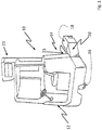
- Fig. 1 shows in a schematic view of a reach truck 10, which has a drive part 12 and a load part 14.
- the truck 10 has a three-wheeled chassis, wherein a drive wheel 16 is arranged on the drive part 12.
- Two load wheels 18 are arranged at the end of the wheel arms 20.
- Between Radar 20 is a mast 21, which can lift a load supporting means 23.
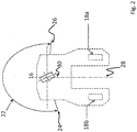
- Fig. 2 shows the three-wheeled chassis in a schematic view.
- the load wheels 18A, 18B respectively steerable and can also be adjusted for better maneuverability of the vehicle via the active steering control.
- the drive wheel 16 is in the illustrated embodiment between a left stop 24 and a right stop 26 over an angular range 22 movable.
- the drive wheel 26 ensures the drive of the entire vehicle.
- a steering mode is a so-called transverse travel, in which all wheels are deflected relative to the vehicle longitudinal axis 28.
- the load wheels 18A and 18B have a deviating from the vehicle longitudinal direction 28 position.
- This may for example also be the steering angle 30, the drive wheel 16 in Fig. 2 has.
- the drive wheel 16 is adjustable via the steering angle range 22 between a steering angle stop 24 and a steering angle stop 26.
- the truck according to the invention it is ensured that in a transverse travel and also during cornering a safe deceleration without a yaw movement about a vertical axis in the drive part or the drive wheel takes place. Due to the uneven load distribution on the truck in a transverse travel with respect to the direction of travel, the adjustment of the braking torque allows a uniform deceleration of the vehicle.
- the electric brakes on the load wheels are still activated in an emergency stop operation can be, since this is an emergency power source is provided.
- a normal driving operation such as a cornering or a transverse drive the web stability and thus the directional stability of the truck can be supported by the brakes of the load wheels individually or jointly and are controlled independently of the brake of the drive wheel.
Landscapes
- Engineering & Computer Science (AREA)
- Transportation (AREA)
- Mechanical Engineering (AREA)
- Chemical & Material Sciences (AREA)
- Combustion & Propulsion (AREA)
- Regulating Braking Force (AREA)
Abstract
Description
- Die vorliegende Erfindung betrifft ein Flurförderzeug mit einer Bremssteuerung.
- Aus
DE 102 51 025 A1 ist eine Bremsvorrichtung für ein Flurförderzeug bekannt geworden, die einen hydraulischen Bremszylinder aufweist, der mit einem Betätigungsorgan gekoppelt und über eine Bremsleitung mit mindestens einer einem Rad des Flurförderzeugs zugeordneten hydraulischen Bremse verbunden ist. Mit der hydraulischen Bremse ist ein weiterer hydraulischer Bremszylinder verbunden, der mit einem Elektromagneten gekoppelt ist, wobei eine Notstoppvorrichtung vorgesehen ist, die ein Bremssignal auf den Elektromagneten zur Betätigung des zweiten Bremszylinders gibt. - Aus
DE 10 2010 044 655 A1 ist ein Flurförderzeug mit einem elektrischen Fahrantrieb vorgesehen, das eine Steuerung aufweist, die den elektrischen Fahrantrieb in einem generatorischen Betrieb zum Abbremsen des Flurförderzeugs umschalten kann, wobei eine Wirbelstrombremse vorgesehen ist, die von der Steuerung während des generatorischen Betriebs zum Abbremsen des Flurförderzeugs angesteuert wird. - Bei Flurförderzeugen mit einem dreirädrigen Fahrwerk, von dem ein gelenktes Antriebsrad und zwei gelenkte Lasträder vorgesehen sind, ist es bekannt, sowohl das Antriebsrad als auch die Lasträder mit einer Bremse auszustatten. Die Lasträder werden über eine hydraulische Bremse gebremst.
- Für ein solches Flurförderzeug ist als ein Fahrmodus eine sogenannte Querfahrt bekannt. Bei der Querfahrt bewegt sich das Flurförderzeug bezogen auf seine durch das Lasttragmittel vorgegebene Längsachse in Querrichtung. Hierzu wird sowohl das Antriebsrad als auch die Lasträder über ihre jeweilige Lenkung quer zur Fahrzeuglängsrichtung gestellt.
- Der Erfindung liegt die Aufgabe zugrunde, ein Flurförderzeug mit einer Bremssteuerung bereitzustellen, die eine spurtreue Fahrt des Fahrzeugs ermöglicht.
- Erfindungsgemäß wird die Aufgabe durch ein Flurförderzeug mit den Merkmalen aus Anspruch 1 gelöst. Vorteilhafte Ausgestaltungen bilden die Gegenstände der Unteransprüche.
- Das erfindungsgemäße Flurförderzeug besitzt ein Antriebsteil und ein Lastteil. Das Antriebsteil weist mindestens ein gelenktes Antriebsrad auf. Das Lastteil besitzt zwei nebeneinander verlaufende Radarme, die jeweils über ein endseitig angeordnetes Lastrad abgestützt sind. Bevorzugt befindet sich zwischen den Radarmen ein höhenverstellbares Lasttragmittel beispielsweise in Form eines Hub- oder Schubmast. Das erfindungsgemäße Flurförderzeug ist ferner mit mindestens einer Lenksteuerung ausgestattet, die das mindestens eine Antriebsrad und mindestens ein Lastrad oder beide Lasträder für eine Lenkung des Fahrzeugs ansteuert. Wenn im Kontext dieser Anmeldung von einer Lenksteuerung und von einer Ansteuerung der Lenkung gesprochen wird, so schließt dies stets die Regelung eines Ist-Werts der Lenkung auf einen vorgegebenen Lenksollwert mit ein. Das erfindungsgemäße Fahrzeug ist zusätzlich zu der Lenksteuerung mit einer Bremssteuerung ausgestattet, die das mindestens eine Antriebsrad und die Lasträder zu einer Bremsung ansteuert. Erfindungsgemäß ist dabei vorgesehen, dass die Bremssteuerung die Lasträder und das mindestens eine Antriebsrad mit jeweils einem Bremsmoment anzusteuern, wenn das ein spurtreues Abbremsen erlaubt. Ferner bestimmt die Bremssteuerung das Bremsmoment für die Lasträder abhängig von dem Bremsmoment für das Antriebsrad und einem oder mehreren Betriebsparametern aus einer Fahrzeugsteuerung. Bei einem Flurförderzeug mit lenkbaren Lasträdern kann die Situation auftreten, in der das Flurförderzeug quer zur Längsrichtung fährt, sogenannte Querfahrt. Bei der Querfahrt tritt die Situation auf, dass das querstehende Antriebsrad und die querstehenden Lasträder sich gemeinsam nach vorn bewegen. In einer solchen Situation sind erfindungsgemäß die Bremsmomente von Antriebsrad und Lastrad aufeinander abzustimmen. Dies trifft nicht nur auf eine Querfahrt unter ungefähr 90° zur Längsrichtung zu, sondern auch bereits bei einer Kurvenfahrt. Erfindungsgemäß wird die Bestimmung des Bremsmoments für die Lasträder abhängig vom Bremsmoment für das Antriebsrad bestimmt. Hierdurch wird ein gieren des Fahrzeugs um eine Vertikalachse verhindert. Das spurtreue Abbremsen wird bestimmt, indem das Bremsmoment für die Lasträder entsprechend angepasst ist. Erfindungsgemäß wird bei der Abstimmung der Bremsmomente zwischen Antriebsrad und den Lasträdern ein oder mehrere Betriebsparameter aus der Fahrzeugsteuerung mit berücksichtigt. Diesem Ansatz liegt die Erkenntnis zugrunde, dass erst eine betriebsparameterabhängige Bremsung von Lasträdern und dem mindestens einem Antriebsrad ein spurtreues Bremsen ermöglichen.
- In einer bevorzugten Ausgestaltung des Flurförderzeugs weisen die Bremseinheiten der Lasträder eine elektrische Bremse auf. Im Gegensatz zu einer hydraulischen Bremse der Lasträder hat eine elektrische Bremse den Vorteil, dass diese deutlich service- und montagefreundlicher ist. Zudem kann eine Wartung der Bremsflüssigkeit entfallen.
- In einer weiteren bevorzugten Ausgestaltung ist mindestens eine den Bremseinheiten der Lasträder zugeordnete Notspannungsquelle vorgesehen, die eine Betätigung der Bremseinheiten auch beim Ausfall einer Versorgungsspannung an Bord zulassen. Die Notspannungsquelle dient dazu, die Bremseinheiten der Lasträder auch bei einem Spannungsausfall noch kontrolliert betätigen zu können. Insbesondere ist die mindestens eine Notspannungsquelle derart ausgelegt, dass im Falle eines Notstopps die Bremssteuerung und die Bremssteuereinheiten der Lasträder mit elektrischer Leistung versorgt werden können. Bevorzugt kann auch die Bremseinheit des mindestens einen Antriebsrads mit elektrischer Leistung für einen kontrollierten Bremsvorgang versorgt werden. Im Falle eines Notstopps, wird über ein Notausschütz in der Regel die gesamte Spannungsversorgung an Bord des Flurförderzeugs unterbunden. Bei einer elektrischen Bremse für die Lasträder, stellt die Notspannungsquelle sicher, dass diese gesteuert abgebremst werden können.
- Bevorzugt ist die Notspannungsquelle als eine Batterie und/oder ein Kondensator ausgeführt. Die Notspannungsquelle muss dabei nicht unbedingt zusammen mit der Hauptspannungsquelle des Flurförderzeugs angeordnet sein, sondern kann auch in den Lastarmen in räumlicher Nähe zu den Lasträdern angeordnet sein.
- In einer bevorzugten Ausgestaltung weisen die Bremseinheiten der Lasträder jeweils eine elektromagnetische Scheibenbremse auf. Für die Bremseinheit für das mindestens eine Antriebsrad kann bevorzugt eine magnetische Federkraftbremse vorgesehen sein.
- In einer besonders bevorzugten Ausgestaltung bestimmt die Bremssteuerung bei einem eine Querfahrt anzeigenden Betriebsparameter das Bremsmoment für die Lasträder derart in Abhängigkeit von dem Bremsmoment des Antriebsrades, dass keine Drehung um eine vertikale Achse erfolgt. Bei der Querfahrt bewegen sich das mindestens eine Antriebsrad und eines der Lasträder in Fahrtrichtung vorweg. Bei einem Abbremsen, insbesondere bei einem Notstopp ist es daher erforderlich, dass beide Räder eine im Wesentlichen gleiche Verzögerung für das Flurförderzeug ausüben. Eine ungleichmäßige Verzögerung an dem Flurförderzeug würde dann zu einem Abweichen aus der Spur, insbesondere zu einer Gierbewegung führen. In dieser Ausgestaltung dient die Querfahrt als ein Betriebsparameter, der für die Bestimmung des Bremsmoments für die Lasträder herangezogen wird. Der Begriff Querfahrt ist in diesem Kontext nicht nur als eine Fahrt in einem 90°-Winkel zur Fahrzeuglängsrichtung zu verstehen, sondern schließt alle Fahrtrichtungen quer zur Fahrzeuglängsrichtung, also abweichend von der Geradeausfahrt mit ein, bei denen die Lasträder gelenkt die quer zur Fahrzeuglängsrichtung stehen.
- In einer weiteren bevorzugten Ausgestaltung bestimmt die Bremssteuerung bei einem eine Querfahrt anzeigenden Betriebsparameter das Bremsmoment für die Lasträder derart in Abhängigkeit von dem Bremsmoment des Antriebsrades und einem oder mehreren Betriebsparametern, das kein Gieren um eine vertikale Achse erfolgt. Hierbei können als Betriebsparameter eine aufgenommene Last, eine Hubhöhe, eine Fahrgeschwindigkeit, ein Lenkwinkel, eine Stellung des Lastteils, beispielsweise eines Hubgerüsts, eine Mastneigung und eine aufgetretene Fahrzeugneigung, beispielsweise durch eine Rampe, mit in die Bestimmung des Bremsmoments für die Lasträder eingehen.
- In einer bevorzugten Ausgestaltung weist das Lastteil einen Schubmast auf, dessen Position als Betriebsparameter von der Bremssteuerung bei der Bestimmung des Bremsmoments für die Lasträder berücksichtigt wird. Insbesondere bei der Querfahrt erfolgt durch die Position des Schubmastes mit oder ohne aufgenommener Last eine ganz wesentliche Lastverschiebung des Flurförderzeugs und der auf das Antriebsrad und die Lasträder wirkenden Kräfte. Für ein spurtreues Abbremsen müssen die Bremsmomente der Lasträder entsprechend angepasst werden.
- Bei dem erfindungsgemäßen Flurförderzeug ist ein manuell betätigbarer Bremssignalgeber vorgesehen, der das Bremsmoment für das mindestens eine Antriebsrad vorgibt. Das Signal des Bremssignalgebers liegt als Sollsignal an der Bremssteuerung an.
- In einer bevorzugten Weiterbildung kann die Bremssteuerung das Bremsmoment auch abhängig von einem oder mehreren Konfigurationsparametern des Fahrzeugs bestimmen. Konfigurationsparameter bestimmen wie ein Fahrzeugtyp genau konfiguriert ist. Konfigurationsparameter betreffen beispielsweise Abmessungen und/oder Gewichte von Last- und Antriebsteil sowie Kenngrößen zu dem Antriebsrad und/oder den Lasträdern. Kenngrößen für die Räder können hierbei Durchmesser und beispielsweise gewisse Reibungskoeffizienten sein. Die Abmessungen und/oder Gewichte von Last- und Antriebsteil umfassen nicht nur das Fahrzeugleergewicht und seine entsprechenden Abmessungen, sondern auch Abmessungen wie maximale Hubhöhe, maximales Traggewicht und dergleichen. In dem in der Weiterbildung die Bremssteuerung ihre Aufgabe abhängig von Konfigurationsparametern ausführt, kann für unterschiedlich konfigurierte Fahrzeuge auf dieselbe Bremssteuerung in Form einer hardwaremäßig vorgesehenen Steuereinheit oder in Form eines Softwareprogramms für eine Steuerung zurückgegriffen werden. Durch Vorgabe der Konfigurationsparameter wählt die Bremssteuerung dann das richtige Bestimmungsverfahren für das Bremsmoment.
- Bei dem erfindungsgemäßen Flurförderzeug ist vorgesehen, dass bei einem Notstopp an dem mindestens einen Antriebsrad ein vorbestimmtes Bremsmoment anliegt, das von der Bremssteuerung auch zur Bestimmung des Bremsmoments für die Lasträder herangezogen wird. Das vorbestimmte Bremsmoment an dem Antriebsrad im Falle eines Notstopps kann als vorbestimmtes Bremsmoment in der Bremssteuerung abgelegt sein oder als aktueller Istwert des Bremsmoments am Fahrzeug gemessen werden.
- Neben dem Messen des Bremsmoments an dem mindestens einen Antriebsrad ist auch ein Messen des Bremsmoments an mindestens einem der Lasträder möglich, wobei dann bevorzugt die Bremssteuerung auf einen vorgegebenen Sollwert für das Bremsmoment regelt.
- In einer weiteren bevorzugten Ausgestaltung ist die Bremssteuerung dazu ausgebildet, auch ohne einen Bremsmoment für die mindestens eine Antriebseinheit ein stabilisierendes Bremsmoment für die Lasträder zu erzeugen. Insbesondere bei einer Kurven- oder Querfahrt können durch das stabilisierende Bremsmoment der Lasträder Spurabweichungen vermieden werden. Gerade mit aufgenommener Last entstehen bei der Kurvenfahrt große nach außen treibende Kräfte, die zu Spurabweichungen an dem Fahrzeug führen können. Diesen Spurabweichungen kann entgegengewirkt werden, indem ein zusätzliches unterstützendes Bremsmoment für die Lasträder erzeugt wird.
- Eine bevorzugte Ausgestaltung eines erfindungsgemäßen Flurförderzeugs wird anhand der Figuren näher erläutert. Es zeigen
- Fig. 1
- einen Schubmaststapler in einer perspektivischen Ansicht auf das Antriebsteil und
- Fig. 2
- eine schematische Ansicht des dreirädrigen Fahrwerks.
-
Fig. 1 zeigt in einer schematischen Ansicht einen Schubmaststapler 10, der ein Antriebsteil 12 und ein Lastteil 14 aufweist. Das Flurförderzeug 10 besitzt ein dreirädriges Fahrwerk, wobei ein Antriebsrad 16 am Antriebsteil 12 angeordnet ist. Zwei Lasträder 18 sind am Ende der Radarme 20 angeordnet. Zwischen den Radarmen 20 befindet sich ein Schubmast 21, der ein Lasttragmittel 23 anheben kann. -
Fig. 2 zeigt das dreirädrige Fahrwerk in einer schematischen Ansicht. Hier sind die Lasträder 18A, 18B jeweils lenkbar und können für eine bessere Wendigkeit des Fahrzeugs ebenfalls über die aktive Lenksteuerung verstellt werden. Das Antriebsrad 16 ist in dem dargestellten Ausführungsbeispiel zwischen einem linken Anschlag 24 und einem rechten Anschlag 26 über einen Winkelbereich 22 verfahrbar. Das Antriebsrad 26 stellt den Antrieb des gesamten Fahrzeugs sicher. - Bei einem solchen dreirädrigen Fahrwerk gibt es verschiedene Modi in denen das Fahrzeug gelenkt werden kann. In einem Lenkmodus liegt eine sogenannte Querfahrt vor, bei der alle Räder relativ zu der Fahrzeuglängsachse 28 ausgelenkt sind. Dies bedeutet, dass anders als in der
Fig. 2 dargestellt auch die Lasträder 18A und 18B eine von der Fahrzeuglängsrichtung 28 abweichende Stellung haben. Dies kann beispielsweise ebenfalls der Lenkwinkel 30 sein, den das Antriebsrad 16 inFig. 2 besitzt. Das Antriebsrad 16 ist über den Lenkwinkelbereich 22 zwischen einem Lenkwinkelanschlag 24 und einem Lenkwinkelanschlag 26 verstellbar. - Bei dem erfindungsgemäßen Flurförderzeug ist sichergestellt, dass bei einer Querfahrt und auch bei einer Kurvenfahrt eine sichere Abbremsung ohne eine Gierbewegung um eine vertikale Achse im Antriebsteil oder das Antriebsrad erfolgt. Durch die ungleichmäßige Lastverteilung an dem Flurförderzeug bei einer Querfahrt bezogen auf die Fahrtrichtung, ermöglicht die Anpassung der Bremsmomente eine gleichmäßige Verzögerung an dem Fahrzeug.
- Weiterhin ist an dem erfindungsgemäßen Fahrzeug besonders vorteilhaft, dass in einem Notstoppbetrieb die elektrischen Bremsen an den Lasträdern noch angesteuert werden können, da hierzu eine Notfallspannungsquelle vorgesehen ist. Auch bei einem normalen Fahrbetrieb wie beispielsweise einer Kurvenfahrt oder einer Querfahrt kann die Bahnstabilität und damit die Spurtreue des Flurförderzeugs unterstützt werden, indem die Bremsen der Lasträder einzeln oder gemeinsam und unabhängig von der Bremse des Antriebsrades angesteuert werden.
-
- 10
- Schubmaststapler
- 12
- Antrieb steil
- 14
- Lastteil
- 16
- Antriebsrad
- 18
- Lasträder
- 18A
- Lastrad
- 18B
- Lastrad
- 20
- Radarme
- 21
- Schubmast
- 22
- Lenkwinkelbereich
- 23
- Lasttragmittel
- 24
- linker Anschlag
- 26
- rechter Anschlag
- 28
- Fahrzeuglängsachse
- 30
- Lenkwinkel
Claims (16)
- Flurförderzeug (10) mit einem Antriebsteil (12), das mindestens ein gelenktes Antriebsrad (16) aufweist, einem Lastteil (14), das zwei nebeneinander verlaufende Radarme (20) besitzt, die jeweils über ein endseitig angeordnetes Lastrad (18) abgestützt sind, und mit mindestens einer Lenksteuerung, die das mindestens eine Antriebsrad (16) und ein oder mehrere Lasträder (18) für eine Lenkung des Fahrzeugs ansteuert, wobei eine Bremssteuerung vorgesehen ist, die das mindestens eine Antriebsrad (16) und die Lasträder (18) zu einer Bremsung ansteuert, dadurch gekennzeichnet, dass- die Bremssteuerung die Lasträder (18) und das mindestens eine Antriebsrad (16) mit jeweils einem Bremsmoment ansteuern, das ein spurtreues Abbremsen erlaubt, und- die Bremssteuerung das Bremsmoment für die Lasträder (18) abhängig von den folgenden Größen bestimmt:• dem Bremsmoment für das mindestens eine Antriebsrad (16) und• einem oder mehreren Betriebsparametern aus einer Fahrzeugsteuerung.
- Flurförderzeug (10) nach Anspruch 1, dadurch gekennzeichnet, dass die Bremseinheiten der Lasträder (18) eine elektrische Bremse aufweisen.
- Flurförderzeug (10) nach Anspruch 2, dadurch gekennzeichnet, dass den Bremseinheiten der Lasträder (18) mindestens eine Notspannungsquelle zugeordnet ist, die eine Betätigung der Bremseinheiten auch bei einem Ausfall einer Spannungsversorgung an Bord zu lassen.
- Flurförderzeug (10) nach einem der Ansprüche 1 bis 3, dadurch gekennzeichnet, dass die mindestens eine Notspannungsquelle derart ausgelegt ist, dass im Falle eines Notstopps die Bremssteuerung und die Bremseinheiten der Lasträder (18) mit elektrischer Leistung versorgt werden kann.
- Flurförderzeug (10) nach Anspruch 3 oder 4, dadurch gekennzeichnet, dass die mindestens eine Notspannungsquelle eine Batterie und/oder einen Kondensator aufweist.
- Flurförderzeug (10) nach einem der Ansprüche 1 bis 5, dadurch gekennzeichnet, dass die Bremseinheiten der Lasträder (18) jeweils eine elektromagnetische Scheibenbremse aufweisen.
- Flurförderzeug (10) nach einem der Ansprüche 1 bis 6, dadurch gekennzeichnet, dass die Bremseinheit für das mindestens eine Antriebsrad (16) eine magnetische Federkraftbremse aufweist.
- Flurförderzeug (10) nach einem der Ansprüche 1 bis 7, dadurch gekennzeichnet, dass die Bremssteuerung bei einem eine Querfahrt anzeigenden Betriebsparameter, das Bremsmoment für die Lasträder (18) derart in Abhängigkeit von dem Bremsmoment des Antriebrades (16) bestimmt, dass keine Drehung um eine vertikale Achse erfolgt.
- Flurförderzeug (10) nach einem der Ansprüche 1 bis 8, dadurch gekennzeichnet, dass die Bremssteuerung bei einem eine Querfahrt anzeigenden Betriebsparameter das Bremsmoment für die Lasträder (18) derart in Abhängigkeit von dem Bremsmoment des Antriebsrades (16) und einem oder mehreren Betriebsparametern, dass keine Drehung um eine vertikale Achse erfolgt, wobei der oder die Betriebsparameter aus folgenden Parametern ausgewählt sind: eine aufgenommene Last, eine Hubhöhe, eine Fahrgeschwindigkeit, ein Lenkwinkel (30), eine Stellung des Lastteils (14) und eine Fahrzeugneigung.
- Flurförderzeug (10) nach einem der Ansprüche 1 bis 9, dadurch gekennzeichnet, dass das Lastteil (14) einen Schubmast (21) aufweist, dessen Position als Betriebsparameter bei der Bestimmung des Bremsmoments für die Lasträder (18) durch die Bremssteuerung mit eingeht.
- Flurförderzeug (10) nach einem der Ansprüche 1 bis 10, dadurch gekennzeichnet, dass das Bremsmoment für das mindestens eine Antriebsrad (16) durch einen manuell betätigbaren Bremssignalgeber an die Bremssteuerung angelegt wird.
- Flurförderzeug (10) nach einem der Ansprüche 1 bis 11, dadurch gekennzeichnet, dass die Bremsteuerung das Bremsmoment abhängig von einem oder mehreren Konfigurationsparametern des Fahrzeugs bestimmt, wobei Konfigurationsparameter des Fahrzeugs Abmessungen und/oder Gewichte von Last- und Antriebsteil (12, 14) und Kenngrößen zu dem Antriebsrad (16) und/oder den Lasträdern (18) aufweisen.
- Flurförderzeug (10) nach einem der Ansprüche 1 bis 12, dadurch gekennzeichnet, dass bei einem Notstopp an dem mindestens einen Antriebsrad (16) ein Bremsmoment anliegt, das von der Bremssteuerung auch zur Bestimmung des Bremsmoments für die Lasträder (18) herangezogen wird.
- Flurförderzeug (10) nach einem der Ansprüche 1 bis 13, dadurch gekennzeichnet, dass eine erste Messeinrichtung für ein Bremsmoment an dem mindestens einen Antriebsrad (16) vorgesehen ist und die Bremssteuerung ausgebildet ist, um das gemessene Bremsmoment zur Bestimmung des Bremsmoments für das mindestens eine Antriebsrad heranzuziehen.
- Flurförderzeug nach einem der Ansprüche 1 bis 14, dadurch gekennzeichnet, dass eine zweite Messeinrichtung für ein Bremsmoment an mindestens einem der Lasträder (18) vorgesehen ist und die Bremssteuerung ausgebildet ist, um das gemessene Bremsmoment auf einen vorgegebenen Sollwert für das Bremsmoment zu regeln.
- Flurförderzeug nach einem der Ansprüche 1 bis 14, dadurch gekennzeichnet, dass bei einer Quer- oder Kurvenfahrt die Bremssteuerung ohne ein Bremsmoment für das mindestens eine Antriebsrad (16) eine stabilisierendes Bremsmoment für die Lasträder (18) erzeugt, um Abweichungen von einer spurtreuen Fahrt entgegen zu wirken.
Applications Claiming Priority (1)
| Application Number | Priority Date | Filing Date | Title |
|---|---|---|---|
| DE102016123104.5A DE102016123104A1 (de) | 2016-11-30 | 2016-11-30 | Flurförderzeug mit einer Bremssteuerung |
Publications (2)
| Publication Number | Publication Date |
|---|---|
| EP3330145A1 true EP3330145A1 (de) | 2018-06-06 |
| EP3330145B1 EP3330145B1 (de) | 2021-06-09 |
Family
ID=60382089
Family Applications (1)
| Application Number | Title | Priority Date | Filing Date |
|---|---|---|---|
| EP17201945.7A Active EP3330145B1 (de) | 2016-11-30 | 2017-11-15 | Flurförderzeug mit einer bremssteuerung |
Country Status (2)
| Country | Link |
|---|---|
| EP (1) | EP3330145B1 (de) |
| DE (1) | DE102016123104A1 (de) |
Citations (6)
| Publication number | Priority date | Publication date | Assignee | Title |
|---|---|---|---|---|
| DE10100743A1 (de) * | 2000-01-14 | 2001-07-19 | Continental Teves Ag & Co Ohg | Verfahren und Vorrichtung zur Regelung des Abbremsens und der Fahrstabilität eines fahrenden Fahrzeugs |
| DE10250764B3 (de) * | 2002-10-29 | 2004-03-04 | Jungheinrich Ag | Verfahren und Vorrichtung zur Lenkung eines Flurförderzeuges |
| DE10258931A1 (de) * | 2002-12-16 | 2004-07-15 | Jungheinrich Aktiengesellschaft | Flurförderzeug mit elektrischer Bremse |
| US7216024B1 (en) * | 1999-07-27 | 2007-05-08 | Linde Aktiengesellschaft | Industrial truck with a stabilizing device |
| EP1985576A2 (de) * | 2007-04-25 | 2008-10-29 | Jungheinrich Aktiengesellschaft | Verfahren und Vorrichtung zur Kippvermeidung eines Gegengewichtsstaplers |
| DE102008011719A1 (de) * | 2008-02-28 | 2009-09-03 | Jungheinrich Aktiengesellschaft | Bremssystem für ein Flurförderzeug |
Family Cites Families (3)
| Publication number | Priority date | Publication date | Assignee | Title |
|---|---|---|---|---|
| DE10251025B4 (de) | 2002-10-30 | 2005-03-03 | Jungheinrich Ag | Flurförderzeug mit einer Bremsvorrichtung |
| DE102010044655A1 (de) | 2010-09-08 | 2012-03-08 | Jungheinrich Aktiengesellschaft | Flurförderzeug mit einem elektrischen Fahrantrieb |
| DE102014202230A1 (de) * | 2014-02-07 | 2015-08-13 | Robert Bosch Gmbh | Verfahren und Vorrichtung zum Verhindern eines Kippens eines lenkbaren Fahrzeugs |
-
2016
- 2016-11-30 DE DE102016123104.5A patent/DE102016123104A1/de not_active Withdrawn
-
2017
- 2017-11-15 EP EP17201945.7A patent/EP3330145B1/de active Active
Patent Citations (6)
| Publication number | Priority date | Publication date | Assignee | Title |
|---|---|---|---|---|
| US7216024B1 (en) * | 1999-07-27 | 2007-05-08 | Linde Aktiengesellschaft | Industrial truck with a stabilizing device |
| DE10100743A1 (de) * | 2000-01-14 | 2001-07-19 | Continental Teves Ag & Co Ohg | Verfahren und Vorrichtung zur Regelung des Abbremsens und der Fahrstabilität eines fahrenden Fahrzeugs |
| DE10250764B3 (de) * | 2002-10-29 | 2004-03-04 | Jungheinrich Ag | Verfahren und Vorrichtung zur Lenkung eines Flurförderzeuges |
| DE10258931A1 (de) * | 2002-12-16 | 2004-07-15 | Jungheinrich Aktiengesellschaft | Flurförderzeug mit elektrischer Bremse |
| EP1985576A2 (de) * | 2007-04-25 | 2008-10-29 | Jungheinrich Aktiengesellschaft | Verfahren und Vorrichtung zur Kippvermeidung eines Gegengewichtsstaplers |
| DE102008011719A1 (de) * | 2008-02-28 | 2009-09-03 | Jungheinrich Aktiengesellschaft | Bremssystem für ein Flurförderzeug |
Also Published As
| Publication number | Publication date |
|---|---|
| DE102016123104A1 (de) | 2018-05-30 |
| EP3330145B1 (de) | 2021-06-09 |
Similar Documents
| Publication | Publication Date | Title |
|---|---|---|
| EP0607226B1 (de) | Lenkungsunterstützung bei einem nicht-spurgebundenen fahrzeug | |
| EP4051554B1 (de) | Verfahren zur steuerung eines kraftfahrzeuges im notlenkbetrieb mittels vorderradbremsen-basierten torque-vectoring | |
| DE102017221289A1 (de) | Risikominimaler Zustand in einem steer-by-wire-Lenksystem | |
| EP4090574A1 (de) | Verfahren zur redundanten steuerung eines elektrischen lenksystems eines kraftfahrzeuges | |
| WO1989006117A1 (fr) | Procede pour stabiliser un vehicule a roues a un seul essieu, et vehicule ainsi stabilise | |
| WO2015007418A1 (de) | Verfahren zum betreiben der lenkung eines kraftfahrzeugs | |
| DE19855310A1 (de) | Aktives Federungssystem für Fahrzeuge | |
| WO2017001116A1 (de) | Verfahren zum lenken eines fahrzeuges, steuerung für ein kraftfahrzeug sowie kraftfahrzeug | |
| DE102014202230A1 (de) | Verfahren und Vorrichtung zum Verhindern eines Kippens eines lenkbaren Fahrzeugs | |
| EP1985576A2 (de) | Verfahren und Vorrichtung zur Kippvermeidung eines Gegengewichtsstaplers | |
| EP0983883B1 (de) | Achsanordnung für ein Fahrzeug und Verfahren zu ihrem Betrieb | |
| DE102011012089B4 (de) | Rangiersystem für einen mehrachsigen Anhänger und ein dazugehöriges Verfahren | |
| DE102019219392A1 (de) | Steer-by-Wire Lenksystem | |
| DE102010021561A1 (de) | Verfahren zur Fahrzeuglenkung mit einer Fahrzeuglenkvorrichtung | |
| DE102015203201A1 (de) | Fahrzeug mit Kontrollkreis zur Kontrolle eines Ist-Gesamtrückstellmoments in einer Lenkanlage sowie Verfahren | |
| EP4339073B1 (de) | Sicherheitssystem zur fahrzeugquerführung für ein steer-by-wire lenksystem eines kraftfahrzeuges, sicherheitsverfahren und kraftfahrzeug | |
| DE102018122991A1 (de) | Lenkbare Achse sowie Fahrzeug mit der Achse | |
| WO2022199991A1 (de) | Verfahren zur steuerung eines fahrzeuges, steuereinrichtung und fahrzeug | |
| DE102015219443B4 (de) | Fahrzeug-Servolenksystem mit elektromotorischer Momentenunterstützung | |
| EP3330145B1 (de) | Flurförderzeug mit einer bremssteuerung | |
| DE102019109155A1 (de) | Antriebslenkanordnung zum Antrieb und zur Lenkung eines Rades eines Radmoduls, Radmodul mit der Antriebslenkanordnung, Fahrzeug mit mindestens einem Radmodul und Verfahren zum Antrieb und zur Lenkung des Rades mit der Antriebslenkanordnung | |
| DE102018004128A1 (de) | Transporteinrichtung mit selektivem Antrieb und Führung eines Rades | |
| BE1032089B1 (de) | Verfahren zum Lenken eines Kraftfahrzeugs und Steer-by-Wire-Lenksystem für ein Kraftfahrzeug | |
| BE1031598B1 (de) | Verfahren zum Steuern eines Kraftfahrzeugs beim Auftreten eines schwerwiegenden Fehlers des Steer-by-Wire-Lenksystems und Notlenksystem | |
| DE102016223360B4 (de) | Antriebsanordnung für ein Fahrzeug sowie Fahrzeug mit der Antriebsanordnung |
Legal Events
| Date | Code | Title | Description |
|---|---|---|---|
| PUAI | Public reference made under article 153(3) epc to a published international application that has entered the european phase |
Free format text: ORIGINAL CODE: 0009012 |
|
| STAA | Information on the status of an ep patent application or granted ep patent |
Free format text: STATUS: THE APPLICATION HAS BEEN PUBLISHED |
|
| AK | Designated contracting states |
Kind code of ref document: A1 Designated state(s): AL AT BE BG CH CY CZ DE DK EE ES FI FR GB GR HR HU IE IS IT LI LT LU LV MC MK MT NL NO PL PT RO RS SE SI SK SM TR |
|
| AX | Request for extension of the european patent |
Extension state: BA ME |
|
| STAA | Information on the status of an ep patent application or granted ep patent |
Free format text: STATUS: REQUEST FOR EXAMINATION WAS MADE |
|
| 17P | Request for examination filed |
Effective date: 20181203 |
|
| RBV | Designated contracting states (corrected) |
Designated state(s): AL AT BE BG CH CY CZ DE DK EE ES FI FR GB GR HR HU IE IS IT LI LT LU LV MC MK MT NL NO PL PT RO RS SE SI SK SM TR |
|
| GRAP | Despatch of communication of intention to grant a patent |
Free format text: ORIGINAL CODE: EPIDOSNIGR1 |
|
| STAA | Information on the status of an ep patent application or granted ep patent |
Free format text: STATUS: GRANT OF PATENT IS INTENDED |
|
| GRAJ | Information related to disapproval of communication of intention to grant by the applicant or resumption of examination proceedings by the epo deleted |
Free format text: ORIGINAL CODE: EPIDOSDIGR1 |
|
| STAA | Information on the status of an ep patent application or granted ep patent |
Free format text: STATUS: REQUEST FOR EXAMINATION WAS MADE |
|
| INTG | Intention to grant announced |
Effective date: 20201117 |
|
| INTC | Intention to grant announced (deleted) | ||
| GRAP | Despatch of communication of intention to grant a patent |
Free format text: ORIGINAL CODE: EPIDOSNIGR1 |
|
| STAA | Information on the status of an ep patent application or granted ep patent |
Free format text: STATUS: GRANT OF PATENT IS INTENDED |
|
| INTG | Intention to grant announced |
Effective date: 20210222 |
|
| GRAS | Grant fee paid |
Free format text: ORIGINAL CODE: EPIDOSNIGR3 |
|
| GRAA | (expected) grant |
Free format text: ORIGINAL CODE: 0009210 |
|
| STAA | Information on the status of an ep patent application or granted ep patent |
Free format text: STATUS: THE PATENT HAS BEEN GRANTED |
|
| AK | Designated contracting states |
Kind code of ref document: B1 Designated state(s): AL AT BE BG CH CY CZ DE DK EE ES FI FR GB GR HR HU IE IS IT LI LT LU LV MC MK MT NL NO PL PT RO RS SE SI SK SM TR |
|
| REG | Reference to a national code |
Ref country code: GB Ref legal event code: FG4D Free format text: NOT ENGLISH |
|
| REG | Reference to a national code |
Ref country code: AT Ref legal event code: REF Ref document number: 1400226 Country of ref document: AT Kind code of ref document: T Effective date: 20210615 Ref country code: CH Ref legal event code: EP |
|
| REG | Reference to a national code |
Ref country code: DE Ref legal event code: R096 Ref document number: 502017010592 Country of ref document: DE |
|
| REG | Reference to a national code |
Ref country code: IE Ref legal event code: FG4D Free format text: LANGUAGE OF EP DOCUMENT: GERMAN |
|
| REG | Reference to a national code |
Ref country code: LT Ref legal event code: MG9D |
|
| REG | Reference to a national code |
Ref country code: SE Ref legal event code: TRGR |
|
| PG25 | Lapsed in a contracting state [announced via postgrant information from national office to epo] |
Ref country code: LT Free format text: LAPSE BECAUSE OF FAILURE TO SUBMIT A TRANSLATION OF THE DESCRIPTION OR TO PAY THE FEE WITHIN THE PRESCRIBED TIME-LIMIT Effective date: 20210609 Ref country code: FI Free format text: LAPSE BECAUSE OF FAILURE TO SUBMIT A TRANSLATION OF THE DESCRIPTION OR TO PAY THE FEE WITHIN THE PRESCRIBED TIME-LIMIT Effective date: 20210609 Ref country code: BG Free format text: LAPSE BECAUSE OF FAILURE TO SUBMIT A TRANSLATION OF THE DESCRIPTION OR TO PAY THE FEE WITHIN THE PRESCRIBED TIME-LIMIT Effective date: 20210909 Ref country code: HR Free format text: LAPSE BECAUSE OF FAILURE TO SUBMIT A TRANSLATION OF THE DESCRIPTION OR TO PAY THE FEE WITHIN THE PRESCRIBED TIME-LIMIT Effective date: 20210609 |
|
| REG | Reference to a national code |
Ref country code: NL Ref legal event code: MP Effective date: 20210609 |
|
| PG25 | Lapsed in a contracting state [announced via postgrant information from national office to epo] |
Ref country code: LV Free format text: LAPSE BECAUSE OF FAILURE TO SUBMIT A TRANSLATION OF THE DESCRIPTION OR TO PAY THE FEE WITHIN THE PRESCRIBED TIME-LIMIT Effective date: 20210609 Ref country code: GR Free format text: LAPSE BECAUSE OF FAILURE TO SUBMIT A TRANSLATION OF THE DESCRIPTION OR TO PAY THE FEE WITHIN THE PRESCRIBED TIME-LIMIT Effective date: 20210910 Ref country code: RS Free format text: LAPSE BECAUSE OF FAILURE TO SUBMIT A TRANSLATION OF THE DESCRIPTION OR TO PAY THE FEE WITHIN THE PRESCRIBED TIME-LIMIT Effective date: 20210609 Ref country code: NO Free format text: LAPSE BECAUSE OF FAILURE TO SUBMIT A TRANSLATION OF THE DESCRIPTION OR TO PAY THE FEE WITHIN THE PRESCRIBED TIME-LIMIT Effective date: 20210909 |
|
| PG25 | Lapsed in a contracting state [announced via postgrant information from national office to epo] |
Ref country code: SK Free format text: LAPSE BECAUSE OF FAILURE TO SUBMIT A TRANSLATION OF THE DESCRIPTION OR TO PAY THE FEE WITHIN THE PRESCRIBED TIME-LIMIT Effective date: 20210609 Ref country code: SM Free format text: LAPSE BECAUSE OF FAILURE TO SUBMIT A TRANSLATION OF THE DESCRIPTION OR TO PAY THE FEE WITHIN THE PRESCRIBED TIME-LIMIT Effective date: 20210609 Ref country code: EE Free format text: LAPSE BECAUSE OF FAILURE TO SUBMIT A TRANSLATION OF THE DESCRIPTION OR TO PAY THE FEE WITHIN THE PRESCRIBED TIME-LIMIT Effective date: 20210609 Ref country code: CZ Free format text: LAPSE BECAUSE OF FAILURE TO SUBMIT A TRANSLATION OF THE DESCRIPTION OR TO PAY THE FEE WITHIN THE PRESCRIBED TIME-LIMIT Effective date: 20210609 Ref country code: RO Free format text: LAPSE BECAUSE OF FAILURE TO SUBMIT A TRANSLATION OF THE DESCRIPTION OR TO PAY THE FEE WITHIN THE PRESCRIBED TIME-LIMIT Effective date: 20210609 Ref country code: NL Free format text: LAPSE BECAUSE OF FAILURE TO SUBMIT A TRANSLATION OF THE DESCRIPTION OR TO PAY THE FEE WITHIN THE PRESCRIBED TIME-LIMIT Effective date: 20210609 Ref country code: PT Free format text: LAPSE BECAUSE OF FAILURE TO SUBMIT A TRANSLATION OF THE DESCRIPTION OR TO PAY THE FEE WITHIN THE PRESCRIBED TIME-LIMIT Effective date: 20211011 Ref country code: ES Free format text: LAPSE BECAUSE OF FAILURE TO SUBMIT A TRANSLATION OF THE DESCRIPTION OR TO PAY THE FEE WITHIN THE PRESCRIBED TIME-LIMIT Effective date: 20210609 |
|
| PG25 | Lapsed in a contracting state [announced via postgrant information from national office to epo] |
Ref country code: PL Free format text: LAPSE BECAUSE OF FAILURE TO SUBMIT A TRANSLATION OF THE DESCRIPTION OR TO PAY THE FEE WITHIN THE PRESCRIBED TIME-LIMIT Effective date: 20210609 |
|
| REG | Reference to a national code |
Ref country code: DE Ref legal event code: R097 Ref document number: 502017010592 Country of ref document: DE |
|
| PLBE | No opposition filed within time limit |
Free format text: ORIGINAL CODE: 0009261 |
|
| STAA | Information on the status of an ep patent application or granted ep patent |
Free format text: STATUS: NO OPPOSITION FILED WITHIN TIME LIMIT |
|
| PG25 | Lapsed in a contracting state [announced via postgrant information from national office to epo] |
Ref country code: DK Free format text: LAPSE BECAUSE OF FAILURE TO SUBMIT A TRANSLATION OF THE DESCRIPTION OR TO PAY THE FEE WITHIN THE PRESCRIBED TIME-LIMIT Effective date: 20210609 |
|
| 26N | No opposition filed |
Effective date: 20220310 |
|
| PG25 | Lapsed in a contracting state [announced via postgrant information from national office to epo] |
Ref country code: AL Free format text: LAPSE BECAUSE OF FAILURE TO SUBMIT A TRANSLATION OF THE DESCRIPTION OR TO PAY THE FEE WITHIN THE PRESCRIBED TIME-LIMIT Effective date: 20210609 |
|
| PG25 | Lapsed in a contracting state [announced via postgrant information from national office to epo] |
Ref country code: MC Free format text: LAPSE BECAUSE OF FAILURE TO SUBMIT A TRANSLATION OF THE DESCRIPTION OR TO PAY THE FEE WITHIN THE PRESCRIBED TIME-LIMIT Effective date: 20210609 |
|
| REG | Reference to a national code |
Ref country code: CH Ref legal event code: PL |
|
| GBPC | Gb: european patent ceased through non-payment of renewal fee |
Effective date: 20211115 |
|
| PG25 | Lapsed in a contracting state [announced via postgrant information from national office to epo] |
Ref country code: LU Free format text: LAPSE BECAUSE OF NON-PAYMENT OF DUE FEES Effective date: 20211115 Ref country code: IT Free format text: LAPSE BECAUSE OF FAILURE TO SUBMIT A TRANSLATION OF THE DESCRIPTION OR TO PAY THE FEE WITHIN THE PRESCRIBED TIME-LIMIT Effective date: 20210609 Ref country code: BE Free format text: LAPSE BECAUSE OF NON-PAYMENT OF DUE FEES Effective date: 20211130 |
|
| REG | Reference to a national code |
Ref country code: BE Ref legal event code: MM Effective date: 20211130 |
|
| PG25 | Lapsed in a contracting state [announced via postgrant information from national office to epo] |
Ref country code: IE Free format text: LAPSE BECAUSE OF NON-PAYMENT OF DUE FEES Effective date: 20211115 Ref country code: GB Free format text: LAPSE BECAUSE OF NON-PAYMENT OF DUE FEES Effective date: 20211115 |
|
| PG25 | Lapsed in a contracting state [announced via postgrant information from national office to epo] |
Ref country code: HU Free format text: LAPSE BECAUSE OF FAILURE TO SUBMIT A TRANSLATION OF THE DESCRIPTION OR TO PAY THE FEE WITHIN THE PRESCRIBED TIME-LIMIT; INVALID AB INITIO Effective date: 20171115 |
|
| PG25 | Lapsed in a contracting state [announced via postgrant information from national office to epo] |
Ref country code: CY Free format text: LAPSE BECAUSE OF FAILURE TO SUBMIT A TRANSLATION OF THE DESCRIPTION OR TO PAY THE FEE WITHIN THE PRESCRIBED TIME-LIMIT Effective date: 20210609 |
|
| PG25 | Lapsed in a contracting state [announced via postgrant information from national office to epo] |
Ref country code: LI Free format text: LAPSE BECAUSE OF NON-PAYMENT OF DUE FEES Effective date: 20220701 Ref country code: CH Free format text: LAPSE BECAUSE OF NON-PAYMENT OF DUE FEES Effective date: 20220701 |
|
| P01 | Opt-out of the competence of the unified patent court (upc) registered |
Effective date: 20230628 |
|
| REG | Reference to a national code |
Ref country code: AT Ref legal event code: MM01 Ref document number: 1400226 Country of ref document: AT Kind code of ref document: T Effective date: 20221115 |
|
| PG25 | Lapsed in a contracting state [announced via postgrant information from national office to epo] |
Ref country code: AT Free format text: LAPSE BECAUSE OF NON-PAYMENT OF DUE FEES Effective date: 20221115 |
|
| PG25 | Lapsed in a contracting state [announced via postgrant information from national office to epo] |
Ref country code: MK Free format text: LAPSE BECAUSE OF FAILURE TO SUBMIT A TRANSLATION OF THE DESCRIPTION OR TO PAY THE FEE WITHIN THE PRESCRIBED TIME-LIMIT Effective date: 20210609 |
|
| PG25 | Lapsed in a contracting state [announced via postgrant information from national office to epo] |
Ref country code: MT Free format text: LAPSE BECAUSE OF FAILURE TO SUBMIT A TRANSLATION OF THE DESCRIPTION OR TO PAY THE FEE WITHIN THE PRESCRIBED TIME-LIMIT Effective date: 20210609 |
|
| PG25 | Lapsed in a contracting state [announced via postgrant information from national office to epo] |
Ref country code: TR Free format text: LAPSE BECAUSE OF FAILURE TO SUBMIT A TRANSLATION OF THE DESCRIPTION OR TO PAY THE FEE WITHIN THE PRESCRIBED TIME-LIMIT Effective date: 20210609 |
|
| PGFP | Annual fee paid to national office [announced via postgrant information from national office to epo] |
Ref country code: DE Payment date: 20251118 Year of fee payment: 9 |
|
| PGFP | Annual fee paid to national office [announced via postgrant information from national office to epo] |
Ref country code: FR Payment date: 20251120 Year of fee payment: 9 |
|
| PGFP | Annual fee paid to national office [announced via postgrant information from national office to epo] |
Ref country code: SE Payment date: 20251119 Year of fee payment: 9 |