EP3328701B1 - Kupplungssystem, insbesondere kupplungssystem zur pneumatischen verbindung einer pneumatischen bremsanlage eines zugfahrzeuges und eines anhängers - Google Patents
Kupplungssystem, insbesondere kupplungssystem zur pneumatischen verbindung einer pneumatischen bremsanlage eines zugfahrzeuges und eines anhängers Download PDFInfo
- Publication number
- EP3328701B1 EP3328701B1 EP16745101.2A EP16745101A EP3328701B1 EP 3328701 B1 EP3328701 B1 EP 3328701B1 EP 16745101 A EP16745101 A EP 16745101A EP 3328701 B1 EP3328701 B1 EP 3328701B1
- Authority
- EP
- European Patent Office
- Prior art keywords
- coupling
- filter unit
- coupling system
- unit
- bypass valve
- Prior art date
- Legal status (The legal status is an assumption and is not a legal conclusion. Google has not performed a legal analysis and makes no representation as to the accuracy of the status listed.)
- Active
Links
Images


Classifications
-
- B—PERFORMING OPERATIONS; TRANSPORTING
- B60—VEHICLES IN GENERAL
- B60T—VEHICLE BRAKE CONTROL SYSTEMS OR PARTS THEREOF; BRAKE CONTROL SYSTEMS OR PARTS THEREOF, IN GENERAL; ARRANGEMENT OF BRAKING ELEMENTS ON VEHICLES IN GENERAL; PORTABLE DEVICES FOR PREVENTING UNWANTED MOVEMENT OF VEHICLES; VEHICLE MODIFICATIONS TO FACILITATE COOLING OF BRAKES
- B60T17/00—Component parts, details, or accessories of power brake systems not covered by groups B60T8/00, B60T13/00 or B60T15/00, or presenting other characteristic features
- B60T17/04—Arrangements of piping, valves in the piping, e.g. cut-off valves, couplings or air hoses
- B60T17/043—Brake line couplings, air hoses and stopcocks
Definitions
- the present invention relates to a coupling system, in particular a coupling system for the pneumatic connection of a pneumatic brake system of a towing vehicle and a trailer.
- Such a tractor vehicle can be, for example, a commercial vehicle such as a truck with a pneumatic brake system.
- Coupling systems with coupling heads for the pneumatic connection of the braking system of a towing vehicle and a trailer are already known from the prior art. These systems have a filter unit for filtering the compressed air flowing through the coupling head.
- Such a coupling head is for example from the DE 199 31 162 A1 or from the DE 2833834 A1 known.
- a coupling head for the pneumatic connection of the brake system of a towing vehicle and a trailer in which a valve device is provided which, when the degree of contamination of the filter unit exceeds a predetermined level of contamination, switches it by means of bypass connections in such a way that the compressed air flowing through the coupling head no longer flows through the filter of the filter unit, but through the bypass connections.
- the coupling system has at least one coupling head with a coupling head housing, the coupling head housing having at least one first coupling connection, at least one second coupling connection and at least one insert recess, which is separate is arranged in relation to the first coupling connection and the second coupling connection in the coupling head housing, and wherein the coupling system furthermore has a filter unit that can be detachably inserted into the insert recess, with a part of the filter unit further providing a sealing surface of a coupling connection in the assembled state of the coupling system.
- the invention is based on the basic idea that the filter unit of the coupling system is not inserted into one of the coupling connections or, via one of the coupling connections, into the coupling head housing, and that part of the seal of a coupling connection is provided by the separately usable filter unit.
- the filter unit should be able to be replaced independently of the assembled state of the clutch system and in particular also in the assembled state.
- the filter unit is detachably inserted as an insert in an insert recess in the coupling head housing. This makes it possible to replace the filter unit or remove it from the clutch housing at any time.
- the separate insert recess provides further access to the at least one pneumatic channel in the interior of the coupling head housing, which connects the two coupling connections to one another.
- the use of the filter unit in the insert recess thus makes it possible to place the filter unit in the pneumatic channel in this way to position between the two coupling connections so that, during normal operation, the medium flowing from one coupling connection to the other coupling connection, for example compressed air, is guided through the filter unit and is thereby filtered.
- This makes it possible to dispense with a separate seal for the coupling connection.
- such a design enables the sealing surface with the filter unit to be easily removed and thus also replaced.
- the sealing surface through the filter unit By providing the sealing surface through the filter unit, the tightness of the coupling head or the coupling connection can be easily ensured and checked. If it is necessary to replace the seal, this can be done in a simple manner, namely by removing the filter unit. This can also be done by the driver of the commercial vehicle, for example. According to the invention, it is thus possible in particular for the maintenance of a coupling system, in particular a coupling system for the pneumatic connection of a pneumatic braking system of a towing vehicle and a trailer, to be simplified and, at the same time, for the coupling system to be structurally simplified and to save weight, material and assembly time.
- the filter unit has a filter support with a sieve, at least one bypass valve opening, at least one bypass valve seat, at least one elastomer unit with valve lips and at least one closure piece.
- This structure enables a simple structure of the filter unit with a bypass valve function.
- a compact structure of the filter unit is possible.
- the filter holder is manufactured together with the sieve or the sieve is installed later and fixed in the filter holder.
- the filter unit is a pre-assembled filter unit. This simplifies the handling of the filter unit and its replacement or, if necessary, its cleaning and reuse.
- the pre-assembled filter unit can be checked before installation in the coupling head housing or can also be tested, for example, with regard to the opening pressures of the lip valves. When cleaning the filter unit or if it is damaged, the filter unit can be easily removed, cleaned, but also replaced. In addition, no further (switching) cover and a cover attachment (usually screwing) is necessary, which leads to a material, weight and assembly time-saving design of the coupling system.
- the filter unit can be a filter unit that is pre-assembled for use in the insert recess. This facilitates the installation and removal of the filter unit in the coupling head housing of the coupling system. This embodiment also makes it possible that no further seal is necessary. Furthermore, the number of parts and thus the weight, the cost of materials and the assembly time can be kept to a minimum.
- the coupling system can have no metal spring. It can in particular be provided that the connection surface of the coupling head can be protected with a cap when not in use.
- a comparable cap was usually mounted on the extension of the housing so that it could be rotated and lifted to a limited extent and was biased with a spring to prevent it from being lifted up.
- the cap can now be made of elastic plastic material, for example, and the storage sleeve can be slotted, for example, to ensure flexibility. This enables safe closing and opening without a metal spring or preload spring. As a result, one component is advantageously saved and there is no longer the problem that the metal spring used as the biasing spring can corrode. Furthermore, contamination of the rotary bearing cannot stop the cap from rotating.
- One of the two coupling connections and the insert recess can be arranged coaxially. This has the advantage that the coupling connection and the insert recess can at least partially use a common bore in the coupling head housing. This simplifies the manufacture of the coupling head housing and thus also lowers the manufacturing costs.
- the filter unit can thus, for example, be arranged opposite to a coupling connection in the coupling head housing.
- the elastomer unit prefferably to form the sealing surface. This enables a further function integration into a component of the filter unit and thus enables a simple construction of the filter unit and the coupling system.
- closure piece can be detachably fastened in a form-fitting manner in the insert recess. This enables simple installation and removal of the filter unit in or out of the coupling head housing.
- closure piece and the insert recess are connectable to one another in the manner of a bayonet closure. This enables a reliable closure, which closes reliably even when the pressures in the coupling system occur.
- bypass valve opening and the bypass valve seat and the elastomer unit with the valve lips form a bypass valve which releases the bypass valve opening in the event of contamination which exceeds a predetermined degree of contamination of the filter unit. This makes it possible to maintain the function of the clutch system despite the filter unit being completely or partially blocked.
- Fig. 1 shows a perspective view of an embodiment of a clutch system K according to the invention.
- the coupling system K is a coupling system K for the pneumatic connection of a pneumatic braking system of a towing vehicle and the trailer (not shown in each case).
- the towing vehicle can be, for example, a commercial vehicle such as a truck with a pneumatic braking system and the trailer can be a pneumatically braked trailer of the commercial vehicle.
- the coupling system K has a coupling head 1 with a coupling head housing 2.
- the coupling head housing 2 has a first coupling connection 2 ′ and a second coupling connection 2 ′′.
- This first coupling connection 2 ' has a threaded attachment, which is used, for example, to connect the coupling connection 2' to the pneumatic system of the towing vehicle.
- the second coupling connection 2 is used in the exemplary embodiment shown for the trailer-side connection.
- an insert recess 3 is provided, which is arranged between the first coupling connection 2 ′ and the second coupling connection 2 ′′.
- the coupling system K also has a filter unit 10 which can be inserted into the insert recess 3.
- a pneumatic channel 7 in the interior of the coupling head housing 2 connects the first coupling connection 2 ′ to the second coupling connection 2 ′′.
- the pneumatic channel 7 is arranged vertically with respect to the insert recess 3.
- the second coupling connection 2 ′′ and the insert recess 3 are arranged coaxially, so that the same bore can be used for these elements of the coupling system K at least for the most part, namely in the central region of the insert recess 3.
- the filter unit 10 is thus inserted in the coupling head housing 2 in exactly the opposite direction to the second coupling connection 2 ′′.
- the filter unit 10 forms together with the elastomer unit 20 with valve lips and with the closure piece 30 (cf. Fig. 2 ) together a pre-assembled unit, which is no longer inserted from the coupling side of the coupling head 1, but from the other side (from below) and fixed (detachably) in the housing 2 of the coupling head 1.
- a cap 41 is arranged on the second coupling connection 2 "and, in the state shown (state" out of operation "), covers the connection surface 40 (e.g. connection to the trailer-side coupling head (not shown)) of the coupling head 1.
- the coupling system K analog for both a towing vehicle and a trailer. This is because the direction of flow of, for example, the compressed air through the coupling system can be reversed, since a first coupling head is usually connected to a further coupling head during operation.
- the two coupling heads can be constructed identically.
- Fig. 2 shows a perspective view of the filter unit 10 of the coupling system K and Fig. 3 a perspective exploded view of the filter unit according to Fig. 2 .
- the filter unit 10 has a filter carrier 11, an elastomer unit 20 and a closure piece 30.
- the filter unit 10 is designed as a preassembled unit and preassembled in the coupling head housing 2.
- the filter unit 10 is a filter unit 10 pre-assembled for use in the insert recess 3.
- the essentially cylindrical filter carrier 11 has an annular rib 12, a contact surface 13, a sieve 14, bypass valve openings 15, 16 and bypass seats 17, 18.
- the toothed contact surface 13 forms one end of the filter carrier 11, which in the assembled state is to be provided for the elastomer unit 20 to be placed on it.
- the annular rib 12 adjoins the contact surface 13.
- the bypass valve openings 15, 16 are arranged adjacent to the annular rib 12.
- the annular rib 12 is thus between the contact surface 13 and the bypass valve openings 15, 16.
- the filter carrier 11 has a plurality of webs 11a.
- the webs 11a are connected to the sieve 14 and together form an essentially cylindrical filter space.
- the elastomer unit 20 is designed as a ring-like sealing element and, in addition to valve lips 24, 25, has a sealing surface 21 which is formed by a radially extending surface of the part of the elastomer unit 20 which connects the two valve lips 24, 25 to one another.
- the elastomer unit has a surface 22 functioning as a sealing surface, an annular groove 23 and an inner surface 26, the function of which is described below.
- the closure piece 30 has an elevation 31, a bevel 32 and securing projections 33, 33 'to form part of a bayonet closure.
- closure piece 30 carries an O-ring 34.
- Fig. 4 shows a further perspective view of the coupling system according to Fig. 1 .
- the counterpart to the locking piece 30, which forms part of the bayonet lock, is located in the entrance area of the insert recess 3.
- a support bracket 4, a nose 5 and a bevel 6 are provided there.
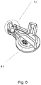
- FIG. 5 shows a further perspective view of the coupling system according to Fig. 1 and Fig. 6 a perspective view of a cap of the clutch system according to Fig. 1 .
- Fig. 5 the cap 41 is shown in a pivoted state, in which the connecting surface 40 of the second coupling connection 2 "is released.
- the sealing surface 21 can also be seen.
- the cap 41 can be pivoted about a bearing sleeve 42.
- the function of the coupling system K can be described as follows:
- the preassembled filter unit 10 can be used to check before installation in the coupling head housing 2 or to test, for example, the opening pressures of the lip valves formed by the valve lips 24, 25 in connection with the bypass valve openings 15, 16.
- the filter unit can be easily removed, cleaned, but also replaced.
- the elastomer unit 20 is designed such that its one surface 21 as a sealing surface to the trailer coupling side, its further surface 22 as a sealing surface to the bore 3 of the coupling head housing 2 and the at least two sealing lips 24, 25 as valve lips for the bypass valves in both Serve directions.
- part of the filter unit 10, namely the elastomer unit 20, provides the sealing surface 21 of the coupling connection 2 ′′.
- the sealing surface 21 is therefore highly stressed because this surface is exposed to movements and friction during the coupling process or during the uncoupling process of the coupling head on the towing vehicle side and the coupling head on the trailer side.
- the fact that the sealing surface 21 is part of the elastomer unit 20 and can be removed without tools from the coupling head housing 2 by removing the filter unit 10 enables a simple and tool-free exchange, for example by the driver of the commercial vehicle.
- the elastomer unit 20 is only plugged onto the filter carrier 11 and can therefore simply be removed. A new elastomer unit 20 can then be placed on the filter carrier 11.
- the elastomer unit 20 is also secured against rotation, e.g. by the tooth-shaped design of the upper contact surface 13 of the filter carrier 11 and by the corresponding design of the inner surface 26 of the elastomer unit 20. This enables a design that saves weight, material and assembly time. In addition, the dimensions and the positions of the functional surfaces are tool-specific and exactly reproducible.
- closure piece 30 and the filter carrier 11, with or without a sieve 14, are produced as one piece or in one piece or at least assembled axially.
- filter unit 10 can simply be removed, cleaned or replaced.
- the closure piece 30 is with a releasable connection, e.g. Bayonet or threaded connection, fixed in the coupling head housing 2 and positioned axially.
- the closure piece 30 can be fastened in a form-fitting manner in the insert recess 3.
- bayonet connection i.e. the locking piece 30 and the insert recess 3 can be connected to one another in the manner of a bayonet lock.
- the bayonet connection is designed in a special shape between the housing 2 and the closure piece 30 in order to save a biasing spring (metal spring).
- the housing bore 3 is at least a partially ring-shaped elevation 4, which is shorter than the distance between the two securing lugs 33, 33 '.
- the support bracket 4 and the separate nose 5 with bevel 6 are formed in the housing bore 3.
- the filter unit 10 When inserting the closure piece 30 or the complete filter unit 10 into the coupling head housing 2, the filter unit 10 is pushed into the housing bore 3 and rotated so far that the two bevels 6, 32 position the closure piece 30 axially so that the two elevations 4, 31 on top of each other issue. In this position, the two securing lugs 33, 33 'together with the lift 4 in the housing bore 3 prevent undesired opening.
- the O-ring 34 is also positioned on the closure piece 30 in order to ensure the tightness to the outside.
- connection can be released and that the secured bayonet connection does not require a built-in spring.
- the filter carrier 11 is produced together with the sieve 14 or the sieve 14 is installed subsequently and fixed in the filter carrier 11.
- the screen 14 can be glued into the filter carrier 11 or alternatively can be fused to the filter carrier 11. It is also conceivable that the sieve 14 is injection molded with the filter carrier 11 (production by co-molding).
- the annular rib 12 of the filter carrier not only has the task of axially positioning the elastomer unit 20, but also the task, together with the inner diameter of the housing bore 3, to secure a pre-tension of the elastomer unit 20 and thus secure tightness.
- the filter carrier 11 has at least two openings 15, 16 and inside and outside surfaces 17, 18, which serve as valve seats.
- the lip valves function in the way, for example, in the DE 10 2009 036 619 A1 is described. In particular, this ensures that the bypass valve openings 15, 16 and the bypass valve seats 17, 18 and the elastomer unit 20 with the valve lips 24, 25 form a bypass valve which releases the bypass valve opening 15, 16 when the filter unit 10 is contaminated to a predetermined degree.
- the connecting surface 40 of the coupling head is protected from operation with a cap 41 (cf. Fig. 1 ).
- the cap 41 is made of elastic plastic material and the bearing sleeve 42 is slotted to ensure flexibility. This enables safe closing and opening without a preload spring.
Landscapes
- Engineering & Computer Science (AREA)
- Transportation (AREA)
- Mechanical Engineering (AREA)
- Transmission Of Braking Force In Braking Systems (AREA)
Description
- Die vorliegende Erfindung betrifft ein Kupplungssystem, insbesondere ein Kupplungssystem zur pneumatischen Verbindung einer pneumatischen Bremsanlage eines Zugfahrzeuges und eines Anhängers.
- Ein derartiges Zugfahrzeug kann beispielsweise ein Nutzfahrzeug wie ein Lastkraftwagen mit einer pneumatischen Bremsanlage sein.
- Aus dem Stand der Technik sind bereits Kupplungssysteme mit Kupplungsköpfen zur pneumatischen Verbindung der Bremsanlage eines Zugfahrzeugs und eines Anhängers bekannt. Diese Systeme weisen eine Filtereinheit zur Filterung der den Kupplungskopf durchströmenden Druckluft auf.
- Ein derartiger Kupplungskopf ist beispielsweise aus der
DE 199 31 162 A1 oder aus derDE 2833834 A1 bekannt. - Aus der
DE 10 2009 036 619 A1 ist beispielsweise ein Kupplungskopf zur pneumatischen Verbindung der Bremsanlage eines Zugfahrzeugs und eines Anhängers bekannt, bei dem eine Ventileinrichtung vorgesehen ist, welche bei einem ein vorgegebenes Maß von Verunreinigung übersteigendes Maß von Verunreinigung der Filtereinheit diese mittels Bypassverbindungen derart schaltet, dass die durch den Kupplungskopf strömende Druckluft nicht mehr durch den Filter der Filtereinheit, sondern durch die Bypassverbindungen strömt. - Die aus dem Stand der Technik bekannten Lösungen erfordern aber im Zusammenhang mit dem Austausch bzw. der Wartung der Filtereinheit bauartbedingt eine aufwendige vollständige Demontage des Kupplungskopfes.
- Es ist daher die Aufgabe der vorliegenden Erfindung, ein Kupplungssystem der eingangs genannten Art in vorteilhafter Weise weiterzubilden, insbesondere dahingehend, dass die Wartung eines Kupplungssystems, insbesondere eines Kupplungssystems zur pneumatischen Verbindung einer pneumatischen Bremsanlage eines Zugfahrzeuges und eines Anhängers vereinfacht und zugleich das Kupplungssystem strukturell vereinfacht und gewichts-, material- und montagezeitsparend ausgebildet werden kann.
- Diese Aufgabe wird erfindungsgemäß gelöst durch ein Kupplungssystem mit den Merkmalen des Anspruchs 1. Danach ist vorgesehen, dass das Kupplungssystem wenigstens einen Kupplungskopf mit einem Kupplungskopfgehäuse aufweist, wobei das Kupplungskopfgehäuse wenigstens einen ersten Koppelungsanschluss, wenigstens einen zweiten Koppelungsanschluss und wenigstens eine Einsatzausnehmung aufweist, die gesondert in Bezug auf den ersten Koppelungsanschluss und den zweiten Koppelungsanschluss im Kupplungskopfgehäuse angeordnet ist, und wobei das Kupplungssystem weiter eine in die Einsatzausnehmung lösbar einsetzbare Filtereinheit aufweist, wobei weiter im montierten Zustand des Kupplungssystems ein Teil der Filtereinheit eine Dichtungsfläche eines Koppelungsanschlusses bereitstellt.
- Die Erfindung basiert auf dem Grundgedanken, dass die Filtereinheit des Kupplungssystems nicht in einen der Koppelungsanschlüsse bzw. über einen der Koppelungsanschlüsse in das Kupplungskopfgehäuse eingesetzt ist und dass durch die gesondert einsetzbare Filtereinheit ein Teil der Dichtung eines Koppelungsanschlusses bereitgestellt wird. Stattdessen soll die Filtereinheit unabhängig vom Montagezustand des Kupplungssystems und insbesondere auch im montierten Zustand gewechselt werden können. Hierzu wird die Filtereinheit als Einsetzteil in eine Einsatzausnehmung im Kupplungskopfgehäuse lösbar eingesetzt. Dadurch wird es möglich, die Filtereinheit jederzeit austauschen bzw. aus dem Kupplungsgehäuse herausnehmen zu können. Durch die separate Einsatzausnehmung wird neben den beiden Koppelungsanschlüssen ein weiterer Zugang zu dem wenigstens einen Pneumatikkanal im Inneren des Kupplungskopfgehäuses geschaffen, der die beiden Koppelungsanschlüsse miteinander verbindet. Der Einsatz der Filtereinheit in die Einsatzausnehmung ermöglicht es somit, die Filtereinheit derart im Pneumatikkanal zwischen den beiden Koppelungsanschlüssen zu positionieren, dass im Normalbetrieb das von einem Koppelungsanschluss zum anderen Koppelungsanschluss strömende Medium, z.B. Druckluft, durch die Filtereinheit geführt und dadurch gefiltert wird. Dadurch wird es möglich, eine gesonderte Dichtung für den Koppelungsanschluss entfallen lassen zu können. Des Weiteren ermöglicht es eine derartige Gestaltung, dass die Dichtungsfläche mit der Filtereinheit einfach entfernt und damit auch getauscht werden kann. Durch die Bereitstellung der Dichtungsfläche durch die Filtereinheit kann die Dichtigkeit des Kupplungskopfes bzw. des Koppelungsangschlusses einfach sichergestellt und geprüft werden. Wenn ein Austausch der Dichtung notwendig wird, kann dies durch einfache Handgriffe, nämlich durch einen Ausbau der Filtereinheit erfolgen. Dies kann z.B. auch durch den Fahrer des Nutzfahrzeugs vorgenommen werden. Erfindungsgemäß wird es also insbesondere möglich, dass die Wartung eines Kupplungssystems, insbesondere eines Kupplungssystems zur pneumatischen Verbindung einer pneumatischen Bremsanlage eines Zugfahrzeuges und eines Anhängers vereinfacht und zugleich das Kupplungssystem strukturell vereinfacht und gewichts-, material- und montagezeitsparend ausgebildet werden kann.
- Des Weiteren kann vorgesehen sein, dass die Filtereinheit einen Filterträger mit einem Sieb, wenigstens einen Bypassventildurchbruch, wenigstens einen Bypassventilsitz, wenigstens eine Elastomereinheit mit Ventillippen und wenigstens ein Verschlussstück aufweist. Dieser Aufbau ermöglicht eine einfache Struktur der Filtereinheit mit einer Bypassventilfunktion. Darüber hinaus ist eine kompakte Struktur der Filtereinheit möglich.
- Der Filterträger wird zusammen mit dem Sieb hergestellt oder das Sieb wird nachträglich eingebaut und im Filterträger fixiert.
- Außerdem ist möglich, dass die Filtereinheit eine vormontierte Filtereinheit ist. Dadurch wird die Handhabung der Filtereinheit und ihr Austausch bzw. ggf. ihre Reinigung und Wiederverwendung vereinfacht. Die vormontierte Filtereinheit kann vor dem Einbau ins Kupplungskopfgehäuse kontrolliert oder auch z.B. bezüglich der Öffnungsdrücke der Lippenventile getestet werden. Bei Reinigung der Filtereinheit oder bei Beschädigung kann die Filtereinheit einfach ausgebaut, gereinigt, aber auch getauscht werden. Außerdem ist kein weiterer (Schalt-)Deckel sowie eine Deckelbefestigung (üblicherweise Verschraubung) nötig, was zu einer material-, gewicht- und montagezeitsparenden Ausbildung des Kupplungssystems führt.
- Dabei kann die Filtereinheit eine fertig für den Einsatz in die Einsatzausnehmung vormontierte Filtereinheit sein. Dies erleichtert den Einbau und auch den Ausbau der Filtereinheit in das Kupplungskopfgehäuse des Kupplungssystems. Diese Ausführungsform ermöglicht es auch, dass keine weitere Dichtung nötig ist. Ferner kann die Zahl der Teile und damit das Gewicht, der Materialaufwand und die Montagezeit minimal gehalten werden.
- Das Kupplungssystem kann in vorteilhafter Ausführung keine Metallfeder aufweisen. Dabei kann insbesondere vorgesehen sein, dass die Verbindungsfläche des Kupplungskopfes außer Betrieb mit einer Kappe geschützt sein kann. Üblicherweise war im Stand der Technik eine vergleichbare Kappe begrenzt drehbar und aufhebbar auf dem Ansatz des Gehäuses gelagert und mit einer Feder gegen Aufheben vorgespannt. Die Kappe kann nun beispielsweise aus elastischem Kunststoffmaterial ausgebildet und die Lagerungshülse kann beispielsweise geschlitzt ausgeführt sein, um die Flexibilität zu sichern. Dadurch wird ein sicheres Schließen und Öffnen ohne Metallfeder bzw. Vorspannfeder möglich. Folglich wird vorteilhafterweise ein Bauteil eingespart und es besteht auch nicht mehr das Problem, dass die als Vorspannfeder eingesetzt Metallfeder korrodieren kann. Des Weiteren kann eine Verschmutzung Drehlagerung das Verdrehen der Kappe nicht stoppen.
- Einer der beiden Koppelungsanschlüsse und die Einsatzausnehmung können koaxial angeordnet sein. Dadurch ergibt sich der Vorteil, dass der Koppelungsanschluss und die Einsatzausnehmung zumindest teilweise eine gemeinsame Bohrung im Kupplungskopfgehäuse nutzen können. Dies vereinfacht die Herstellung des Kupplungskopfgehäuses und senkt damit auch die Herstellungskosten.
- Die Filtereinheit kann somit beispielsweise entgegengesetzt zu einem Koppelungsanschluss im Kupplungskopfgehäuse angeordnet sein.
- Insbesondere ist möglich, dass die Elastomereinheit die Dichtungsfläche ausbildet. Dies ermöglicht eine weitere Funktionsintegration in ein Bauteil der Filtereinheit und ermöglicht so insgesamt einen einfachen Aufbau der Filtereinheit und des Kupplungssystems.
- Des Weiteren kann vorgesehen sein, dass das Verschlussstück formschlüssig in der Einsatzausnehmung lösbar befestigbar ist. Dadurch wird ein einfacher Einbau und Ausbau der Filtereinheit in bzw. aus dem Kupplungskopfgehäuse möglich.
- Insbesondere ist möglich, dass das Verschlussstück und die Einsatzausnehmung nach Art eines Bajonettverschlusses miteinander verbindbar sind. Dies ist ermöglicht einen zuverlässigen Verschluss, der auch bei den auftretenden Drücken im Kupplungssystem zuverlässig schließt.
- Außerdem kann vorgesehen, dass der Bypassventildurchbruch und der Bypassventilsitz und die Elastomereinheit mit den Ventillippen ein Bypassventil ausbilden, das bei einer Verunreinigung, die ein vorgegebenes Maß an Verunreinigung der Filtereinheit übersteigt, den Bypassventildurchbruch freigibt. Dadurch wird es möglich, trotz ganz oder teilweise verstopfter Filtereinheit die Funktion des Kupplungssystems aufrecht zu erhalten.
- Weitere Einzelheiten und Vorteile der Erfindung sollen nun anhand eines in den Zeichnungen dargestellten Ausführungsbeispiels näher dargestellt werden. Es zeigen:
- Fig. 1
- eine perspektivische Ansicht auf ein erfindungsgemäßes Ausführungsbeispiels eines Kupplungssystems;
- Fig. 2
- eine perspektivische Ansicht auf eine Filtereinheit des Kupplungssystems gemäß
Fig. 1 ; - Fig. 3
- eine perspektivische Explosionsdarstellung der Filtereinheit gemäß
Fig. 2 ; - Fig. 4
- eine weitere perspektivische Ansicht auf das Kupplungssystem gemäß
Fig. 1 ; - Fig. 5
- eine weitere perspektivische Ansicht auf das Kupplungssystem gemäß
Fig. 1 ; und - Fig. 6
- eine perspektivische Ansicht auf eine Kappe des Kupplungssystems gemäß
Fig. 1 . -
Fig. 1 zeigt eine perspektivische Ansicht auf ein erfindungsgemäßes Ausführungsbeispiel eines Kupplungssystems K. - Das Kupplungssystem K ist in der gezeigten Ausführungsform ein Kupplungssystem K zur pneumatischen Verbindung einer pneumatischen Bremsanlage eines Zugfahrzeuges und des Anhängers (jeweils nicht näher dargestellt). Bei dem Zugfahrzeug kann es sich beispielsweise um ein Nutzfahrzeug wie einen Lastkraftwagen mit einer pneumatischen Bremsanlage und bei dem Anhänger um einen pneumatisch gebremsten Anhänger des Nutzfahrzeugs handeln.
- Das Kupplungssystem K weist eine Kupplungskopf 1 mit einem Kupplungskopfgehäuse 2 auf.
- Das Kupplungskopfgehäuse 2 weist einen ersten Koppelungsanschluss 2' und einen zweiten Koppelungsanschluss 2" auf.
- Dieser erste Koppelungsanschluss 2' weist einen Gewindeansatz auf, der beispielsweise zum Anschluss des Koppelungsanschlusses 2' an das Pneumatiksystem des Zugfahrzeugs dient.
- Der zweite Koppelungsanschluss 2" dient im gezeigten Ausführungsbeispiel zum anhängerseitigen Anschluss.
- Weiter ist eine Einsatzausnehmung 3 vorgesehen, die zwischen dem ersten Koppelungsanschluss 2' und dem zweiten Koppelungsanschluss 2" angeordnet ist.
- Das Kupplungssystem K weist weiter eine in die Einsatzausnehmung 3 lösbar einsetzbare Filtereinheit 10 auf.
- Ein Pneumatikkanal 7 im Inneren des Kupplungskopfgehäuses 2 verbindet den ersten Koppelungsanschluss 2' mit dem zweiten Koppelungsanschluss 2".
- Der Pneumatikkanal 7 ist senkrecht in Bezug auf die Einsatzausnehmung 3 angeordnet.
- Der zweite Koppelungsanschluss 2" und die Einsatzausnehmung 3 sind koaxial angeordnet, so dass für diese Elemente des Kupplungssystems K zumindest großteils, nämlich im mittleren Bereich der Einsatzausnehmung 3 dieselbe Bohrung verwendet werden kann.
- Die Filtereinheit 10 wird somit genau entgegengesetzt zum zweiten Koppelungsanschluss 2" in das Kupplungskopfgehäuse 2 eingesetzt.
- Die Filtereinheit 10 bildet zusammen mit der Elastomer-Einheit 20 mit Ventillippen und mit dem Verschlussstück 30 (vgl.
Fig. 2 ) zusammen eine vormontierte Einheit, was nicht mehr von der Koppelungsseite des Kupplungskopfes 1, aber von der anderen Seite (von unten) eingelegt und im Gehäuse 2 des Kupplungskopfes 1 (lösbar) fixiert ist. - Eine Kappe 41 ist an dem zweiten Koppelungsanschluss 2" angeordnet und deckt im gezeigten Zustand (Zustand "außer Betrieb") die Verbindungsfläche 40 (z.B. Verbindung zum nicht näher dargestellten anhängerseitigen Kupplungskopf) des Kupplungskopfes 1 ab.
- Wie in der
DE 10 2009 036 619 A1 beschrieben, ist es grundsätzlich möglich, das Kupplungssystem K analog sowohl für ein Zugfahrzeug als auch für einen Anhänger zu verwenden. Denn die Strömungsrichtung z.B. der Druckluft durch das Kupplungssystem kann umgekehrt werden, da im Betrieb ein erster Kupplungskopf üblicherweise mit einem weiteren Kupplungskopf verbunden wird. Die beiden Kupplungsköpfe können baugleich ausgeführt sein. -
Fig. 2 zeigt eine perspektivische Ansicht auf die Filtereinheit 10 des Kupplungssystems K undFig. 3 eine perspektivische Explosionsdarstellung der Filtereinheit gemäßFig. 2 . - Die Filtereinheit 10 weist einen Filterträger 11, eine Elastomer-Einheit 20 und einen Verschlussstück 30 auf.
- Die Filtereinheit 10 ist als vormontierte Einheit ausgebildet und vormontiert ins Kupplungskopfgehäuse 2 eingebaut.
- Mit anderen Worten ist die Filtereinheit 10 eine fertig für den Einsatz in die Einsatzausnehmung 3 vormontierte Filtereinheit 10.
- Der im Wesentlichen zylindrische Filterträger 11 weist eine Ringrippe 12, eine Kontaktfläche 13, ein Sieb 14, Bypassventil-Durchbrüche 15, 16 und Bypass-Sitze 17, 18 auf.
- Die gezahnte Kontaktfläche 13 bildet ein Ende des Filterträgers 11, das im montierten Zustand dafür vorsehen ist, dass hierauf die Elastomer-Einheit 20 aufgesetzt wird.
- An die Kontaktfläche 13 schließt die Ringrippe 12 an. Benachbart zur Ringrippe 12 sind die Bypassventil-Durchbrüche 15, 16 angeordnet. Die Ringrippe 12 befindet sich damit zwischen der Kontaktfläche 13 und den Bypassventil-Durchbrüchen 15, 16.
- Im Anschluss an die Bypassventil-Durchbrüche 15, 16 und die Bypass-Sitze 17, 18 weist der Filterträger 11 mehrere Stege 11a auf.
- Die Stege 11a sind mit dem Sieb 14 verbunden und bilden gemeinsam einen im Wesentlichen zylindrischen Filterraum aus.
- Die Elastomer-Einheit 20 ist als ringartiges Dichtelement ausgebildet und weist neben Ventillippen 24, 25 eine Dichtfläche 21 auf, die durch eine radial sich erstreckende Oberfläche des Teils der Elastomer-Einheit 20 ausgebildet wird, der die beiden Ventillippen 24, 25 miteinander verbindet.
- Des Weiteren weist die Elastomereinheit eine als Dichtfläche fungierende Fläche 22, eine Ringnut 23 und eine innere Fläche 26 auf, deren Funktion nachfolgend beschrieben wird.
- Das Verschlussstück 30 weist zur Ausbildung eines Teils eines Bajonettverschlusses eine Hebung 31, eine Schräge 32 sowie Sicherungsansätze 33, 33' auf.
- Des Weiteren trägt das Verschlussstück 30 einen O-Ring 34.
-
Fig. 4 zeigt eine weitere perspektivische Ansicht auf das Kupplungssystem gemäßFig. 1 . - Das Gegenstück zum Verschlussstück 30, das einen Teil des Bajonettverschlusses ausbildet, findet sich im Eingangsbereich der Einsatzausnehmung 3. Dort sind eine Auflagehebung 4, eine Nase 5 sowie eine Schräge 6 vorgesehen.
-
Fig. 5 zeigt eine weitere perspektivische Ansicht auf das Kupplungssystem gemäßFig. 1 undFig. 6 eine perspektivische Ansicht auf eine Kappe des Kupplungssystems gemäßFig. 1 . - In
Fig. 5 ist der Kappe 41 in einem verschwenkten Zustand gezeigt, in dem die Verbindungsfläche 40 des zweiten Koppelungsanschlusses 2" freigegeben ist. Auch die Dichtungsfläche 21 ist ersichtlich. - Wie aus
Fig. 6 ersichtlich ist, kann die Kappe 41 um eine Lagerungshülse 42 verschwenkt werden. - Die Funktion der Kupplungssystems K lässt sich wie folgt beschreiben:
Durch die vormontierte Filtereinheit 10 kann vor dem Einbau ins Kupplungskopfgehäuse 2 kontrolliert oder auch z.B. bezüglich der Öffnungsdrücke der Lippenventile ausgebildet durch die Ventillippen 24, 25 im Zusammenhang mit den Bypassventil-Durchbrüchen 15, 16 getestet werden. - Für eine Reinigung des Siebs 14 oder irgendwelche Beschädigung kann die Filtereinheit einfach ausgebaut, gereinigt, aber auch getauscht werden.
- So ist kein weiterer (Schalt-)Deckel sowie eine gesonderte Deckelbefestigung (üblicherweise Verschraubung) nötig, was zu einer material-, gewicht- und montagezeitsparende Ausbildung führt.
- Die Elastomer-Einheit 20 ist so ausgebildet, dass ihre eine Fläche 21 als Dichtungsfläche zum anhängerseitigen Kupplungskopf, ihre weitere Fläche 22 als Dichtungsfläche zu der Bohrung 3 des Kupplungskopfgehäuses 2 und die wenigstens zwei Dichtungslippen 24, 25 als Ventillippen für die Bypass-Ventile in beiden Richtungen dienen.
- So stellt im montierten Zustand des Kupplungssystems K ein Teil der Filtereinheit 10, nämlich die Elastomer-Einheit 20, die Dichtungsfläche 21 des Koppelungsanschlusses 2" bereit.
- Dadurch wird es einfach möglich, die vielbeanspruchte Dichtungsfläche 21, die als Dichtungsfläche des Koppelungsanschlusses 2" dient, einfach bei etwaig auftretender Beschädigung wechseln zu können. So ist es einfach, im Betrieb stets die Dichtigkeit des Koppelungsanschlusses 2" sicherstellen zu können.
- Die Dichtungsfläche 21 ist deshalb hoch beansprucht, weil diese Fläche Bewegungen und Reibung während des Kupplungsvorgangs bzw. während des Entkupplungsvorgangs von zugfahrzeugseitigen Kupplungskopf und anhängerseitigem Kupplungskopf ausgesetzt ist. Dadurch, dass die Dichtungsfläche 21 Teil der Elastomereinheit 20 ist und werkzeuglos durch Entnahme der Filtereinheit 10 aus dem Kupplungskopfgehäuse 2 entnommen werden kann, ist ein einfacher und werkzeugloser Austausch z.B. durch den Fahrer des Nutzfahrzeugs möglich.
- Die Elastomer-Einheit 20 ist lediglich auf den Filterträger 11 aufgesteckt und kann daher einfach abgezogen werden. Sodann kann eine neue Elastomer-Einheit 20 auf den Filterträger 11 aufgesetzt werden.
- Die Ringnut 23 in der Elastomer-Einheit 20 positioniert zusammen mit der Ringrippe 12 des Filterträgers 11 die Elastomer-Einheit 20 axial.
- Die Elastomer-Einheit 20 ist zudem auch gegen Verdrehung gesichert, und zwar z.B. durch die zahnförmige Ausbildung der oberen Kontaktfläche 13 des Filterträgers 11 sowie durch die entsprechende Ausbildung der inneren Fläche 26 der Elastomer-Einheit 20. Dies ermöglicht eine gewicht-, material- und montagezeitsparende Ausbildung. Außerdem sind die Abmessungen und die Positionen der Funktionsflächen werkzeuggebunden und genau reproduzierbar.
- Das Verschlussstück 30 und der Filterträger 11, mit oder ohne Sieb 14, sind als ein Stück bzw. einstückig hergestellt oder wenigstens axial zusammengebaut.
- Dadurch kann die Höhe der Filtereinheit 10 gut kontrolliert werden, d.h. hierdurch wird sichergestellt, dass die Dichtfläche 21 im montierten Zustand richtig positioniert ist.
- Nicht zuletzt dadurch kann bei Reinigung des Filters oder bei anderen Fehlern Filtereinheit 10 einfach zusammen ausgebaut, gereinigt oder getauscht werden.
- Das Verschlussstück 30 ist mit lösbarer Verbindung, wie z.B. Bajonett- oder GewindeVerbindung, im Kupplungskopfgehäuse 2 fixiert und axial positioniert. Das Verschlussstück 30 ist formschlüssig in der Einsatzausnehmung 3 lösbar befestigbar.
- In den Figuren ist nur die Bajonett-Verbindung dargestellt, d.h., dass das Verschlussstück 30 und die Einsatzausnehmung 3 nach Art eines Bajonettverschlusses miteinander verbindbar sind.
- Grundsätzlich ist jegliche Art von lösbarer Verbindung denkbar. Insbesondere sind werkzeuglos zu öffnende Verbindungen vorteilhaft.
- Die Bajonett-Verbindung ist in einer speziellen Form zwischen dem Gehäuse 2 und dem Verschlussstück 30 ausgebildet, um eine Vorspannfeder (Metallfeder) zu sparen. Auf dem Verschlussstück 30 sind die wenigstens eine teilweise ringlaufende Hebung 31 mit Schräge 32 und je zwei Sicherungsansätze 33, 33' ausgebildet.
- In der Gehäusebohrung 3 ist wenigstens eine teilweise ringlaufende Hebung 4, die kürzer ist, als die Entfernung zwischen den zwei Sicherungsansätzen 33, 33'. Es ist in der Gehäusebohrung 3 die Auflagehebung 4 und die separate Nase 5 mit Schräge 6 ausgebildet.
- Beim Einlegen des Verschlussstücks 30 bzw. der kompletten Filtereinheit 10 in das Kupplungskopfgehäuse 2 wird die Filtereinheit 10 in die Gehäusebohrung 3 eingeschoben und soweit verdreht, dass die zwei Schrägen 6, 32 das Verschlussstück 30 axial so positionieren, dass die zwei Hebungen 4, 31 aufeinander anliegen. In dieser Position verhindern die zwei Sicherungsansätze 33, 33' zusammen mit der Hebung 4 in der Gehäusebohrung 3 ein ungewünschtes Öffnen. Auf dem Verschlussstück 30 ist weiterhin der O-Ring 34 positioniert, um die Dichtheit nach außen hin zu sichern.
- Besonders vorteilhaft ist, dass die Verbindung lösbar ist und dass die gesicherte Bajonett-Verbindung ohne eingebaute Feder auskommt.
- Der Filterträger 11 wird zusammen mit dem Sieb 14 hergestellt oder das Sieb 14 wird nachträglich eingebaut und im Filterträger 11 fixiert. Das Sieb 14 kann in den Filterträger 11 eingeklebt oder alternativ mit dem Filterträger 11 verschmolzen sein. Denkbar ist auch, dass das Sieb 14 mit dem Filterträger 11 mitgespritzt (Herstellung durch Co-Molding) wird.
- Die Ringrippe 12 des Filterträgers hat nicht nur die Aufgabe, die Elastomer-Einheit 20 axial zu positionieren, sondern auch die Aufgabe, zusammen mit dem inneren Durchmesser der Gehäusebohrung 3 eine Vorspannung der Elastomer-Einheit 20 und damit eine sichere Dichtheit zu sichern. Der Filterträger 11 hat wenigstens zwei Durchbrüche 15, 16 und innen und außen Flächen 17, 18, die als Ventilsitze dienen.
- Die Lippenventile funktionieren derart, wie es beispielsweise in der
DE 10 2009 036 619 A1 beschrieben ist. Insbesondere wird hierdurch erreicht, dass die Bypassventildurchbrüche 15, 16 und die Bypassventilsitze 17, 18 und die Elastomereinheit 20 mit den Ventillippen 24, 25 ein Bypassventil ausbilden, das bei einer ein vorgegebenes Maß an Verunreinigung der Filtereinheit 10 den Bypassventildurchbruch 15, 16 freigibt. - Die Verbindungsfläche 40 des Kupplungskopfes ist außer Betrieb mit einer Kappe 41 geschützt (vgl.
Fig. 1 ). Die Kappe 41 ist aus elastischem Kunststoffmaterial ausgebildet und die Lagerungshülse 42 ist geschlitzt ausgebildet, ist um die Flexibilität zu sichern. Dadurch wird ein sicheres Schließen und Öffnen ohne Vorspannfeder möglich. -
- 1
- Kupplungskopf
- 2
- Gehäuse; Kupplungskopfgehäuse
- 2'
- erster Koppelungsanschluss
- 2"
- zweiter Koppelungsanschluss
- 3
- Einsatzausnehmung; Gehäusebohrung
- 4
- Auflagehebung
- 5
- Nase
- 6
- Schräge
- 7
- Pneumatikkanal
- 10
- Filtereinheit
- 11
- Filterträger
- 11a
- Steg
- 12
- Ringrippe
- 13
- Kontaktfläche
- 14
- Sieb
- 15
- Durchbruch
- 16
- Durchbruch
- 17
- Fläche; Sitz
- 18
- Fläche; Sitz
- 20
- Elastomer-Einheit
- 21
- Dichtfläche
- 22
- Fläche
- 23
- Ringnut
- 24
- Dichtungslippe; Ventilippe
- 25
- Dichtungslippe; Ventillippe
- 26
- innere Fläche
- 30
- Verschlussstück
- 31
- Hebung
- 32
- Schräge
- 33
- Sicherungsansatz
- 33'
- Sicherungsansatz
- 34
- O-Ring
- 40
- Verbindungsfläche
- 41
- Kappe
- 42
- Lagerungshülse
- K
- Kupplungssystem
Claims (8)
- Kupplungssystem (K), insbesondere Kupplungssystem (K) zur pneumatischen Verbindung einer pneumatischen Bremsanlage eines Zugfahrzeuges und eines Anhängers, aufweisend einen Kupplungskopf (1) mit einem Kupplungskopfgehäuse (2), wobei das Kupplungskopfgehäuse (2) wenigstens einen ersten Koppelungsanschluss (2'), wenigstens einen zweiten Koppelungsanschluss (2") und wenigstens eine Einsatzausnehmung (3) aufweist, die gesondert in Bezug auf den ersten Koppelungsanschluss (2') und den zweiten Koppelungsanschluss (2") im Kupplungskopfgehäuse (2) angeordnet ist, und wobei das Kupplungssystem (K) weiter eine in die Einsatzausnehmung (3) lösbar einsetzbare Filtereinheit (10) aufweist, wobeiim montierten Zustand des Kupplungssystems (K) ein Teil der Filtereinheit (10) eine Dichtungsfläche (21) eines Koppelungsanschlusses (2") bereitstellt, dadurch gekennzeichnet, dass die Filtereinheit (10) einen Filterträger (11) mit einem Sieb (14), mit wenigstens einem Bypassventildurchbruch (15, 16) und wenigstens einem Bypassventilsitz (17, 18), sowie weiter wenigstens eine Elastomereinheit (20) mit Ventillippen (24, 25) und wenigstens ein Verschlussstück (30) aufweist.
- Kupplungssystem (K) nach Anspruch 1,
dadurch gekennzeichnet, dass
die Filtereinheit (10) eine vormontierte Filtereinheit (10) ist, insbesondere wobei die Filtereinheit (10) eine fertig für den Einsatz in die Einsatzausnehmung (3) vormontierte Filtereinheit (10) ist. - Kupplungssystem (K) nach Anspruch 1 oder 2,
dadurch gekennzeichnet, dass
der Kupplungskopf (K) keine Metallfeder aufweist. - Kupplungssystem (K) nach einem der vorhergehenden Ansprüche,
dadurch gekennzeichnet, dass
einer der beiden Koppelungsanschlüsse (2") und die Einsatzausnehmung (3) koaxial angeordnet sind. - Kupplungssystem (K) nach einem der vorhergehenden Ansprüche,
dadurch gekennzeichnet, dass
die Elastomereinheit (20) die Dichtungsfläche (21) ausbildet. - Kupplungssystem (K) nach einem der vorhergehenden Ansprüche,
dadurch gekennzeichnet, dass
das Verschlusstück (30) formschlüssig in der Einsatzausnehmung (3) lösbar befestigbar ist. - Kupplungssystem (K) nach Anspruch 6,
dadurch gekennzeichnet, dass
das Verschlussstück (30) und die Einsatzausnehmung (3) nach Art eines Bajonettverschlusses miteinander verbindbar sind. - Kupplungssystem (K) nach einem der vorhergehenden Ansprüche,
dadurch gekennzeichnet, dass
der Bypassventildurchbruch (15, 16) und der Bypassventilsitz (17, 18) und die Elastomereinheit (20) mit den Ventillippen (24, 25) ein Bypassventil ausbilden, das bei einer Verunreinigung der Filtereinheit (10), die ein vorgegebenes Maß an Verunreinigung der Filtereinheit (10) übersteigt, den Bypassventildurchbruch (15, 16) freigibt.
Priority Applications (1)
| Application Number | Priority Date | Filing Date | Title |
|---|---|---|---|
| PL16745101T PL3328701T3 (pl) | 2015-07-30 | 2016-07-28 | Układ sprzęgający, w szczególności układ sprzęgający do pneumatycznego połączenia pneumatycznego układu hamulcowego pojazdu ciągnikowego i przyczepy |
Applications Claiming Priority (2)
| Application Number | Priority Date | Filing Date | Title |
|---|---|---|---|
| DE102015112487.4A DE102015112487A1 (de) | 2015-07-30 | 2015-07-30 | Kupplungssystem, insbesondere Kupplungssystem zur pneumatischen Verbindung einer pneumatischen Bremsanlage eines Zugfahrzeuges und eines Anhängers |
| PCT/EP2016/067977 WO2017017170A1 (de) | 2015-07-30 | 2016-07-28 | Kupplungssystem, insbesondere kupplungssystem zur pneumatischen verbindung einer pneumatischen bremsanlage eines zugfahrzeuges und eines anhängers |
Publications (2)
| Publication Number | Publication Date |
|---|---|
| EP3328701A1 EP3328701A1 (de) | 2018-06-06 |
| EP3328701B1 true EP3328701B1 (de) | 2020-04-08 |
Family
ID=56555389
Family Applications (1)
| Application Number | Title | Priority Date | Filing Date |
|---|---|---|---|
| EP16745101.2A Active EP3328701B1 (de) | 2015-07-30 | 2016-07-28 | Kupplungssystem, insbesondere kupplungssystem zur pneumatischen verbindung einer pneumatischen bremsanlage eines zugfahrzeuges und eines anhängers |
Country Status (4)
| Country | Link |
|---|---|
| EP (1) | EP3328701B1 (de) |
| DE (1) | DE102015112487A1 (de) |
| PL (1) | PL3328701T3 (de) |
| WO (1) | WO2017017170A1 (de) |
Families Citing this family (2)
| Publication number | Priority date | Publication date | Assignee | Title |
|---|---|---|---|---|
| WO2018209079A1 (en) * | 2017-05-12 | 2018-11-15 | Tectran Mfg. Inc. | Serviceable filter gladhand assembly |
| US10927968B2 (en) * | 2018-12-12 | 2021-02-23 | Bendix Commercial Vehicle Systems Llc | Pneumatic valve/pressure vessel plastic metal composite cover with bayonet retention feature |
Family Cites Families (3)
| Publication number | Priority date | Publication date | Assignee | Title |
|---|---|---|---|---|
| DE2833834C2 (de) * | 1978-08-02 | 1982-07-01 | Graubremse Gmbh, 6900 Heidelberg | Luftfilter |
| DE19931162B4 (de) | 1999-07-06 | 2004-07-08 | Knorr-Bremse Systeme für Nutzfahrzeuge GmbH | Kupplungskopf zur pneumatischen Verbindung der Bremsanlagen eines Motorwagens und eines Anhängefahrzeuges |
| DE102009036619A1 (de) | 2009-08-07 | 2011-02-10 | Knorr-Bremse Systeme für Nutzfahrzeuge GmbH | Kupplungskopf zur pneumatischen Verbindung der Bremsanlagen eines Zugfahrzeugs und eines Anhängers mit Lippenventil |
-
2015
- 2015-07-30 DE DE102015112487.4A patent/DE102015112487A1/de not_active Withdrawn
-
2016
- 2016-07-28 EP EP16745101.2A patent/EP3328701B1/de active Active
- 2016-07-28 WO PCT/EP2016/067977 patent/WO2017017170A1/de unknown
- 2016-07-28 PL PL16745101T patent/PL3328701T3/pl unknown
Non-Patent Citations (1)
| Title |
|---|
| None * |
Also Published As
| Publication number | Publication date |
|---|---|
| EP3328701A1 (de) | 2018-06-06 |
| WO2017017170A1 (de) | 2017-02-02 |
| PL3328701T3 (pl) | 2020-09-21 |
| DE102015112487A1 (de) | 2017-02-02 |
Similar Documents
| Publication | Publication Date | Title |
|---|---|---|
| EP2490784B1 (de) | Filtervorrichtung sowie filterelement für den einsatz bei einer solchen filtervorrichtung | |
| EP1154831B1 (de) | Flüssigkeitsfilter mit demontierbarem, zentralen bauteil, mit zusätzlichem haltebauteil | |
| DE102009048412B3 (de) | Filtersystem und Filterelement zur Filtrierung von Fluiden | |
| EP2956225B1 (de) | Filtereinrichtung | |
| DE102006039826B4 (de) | Filtervorrichtung, Filterelement sowie Verfahren zum Betrieb der Filtervorrichtung | |
| DE102017005619A1 (de) | Hohlfilterelement, Filter und Gehäuseteil eines Filters | |
| EP3096859B1 (de) | Filterelement | |
| DE112010003242T5 (de) | "Kein Filter kein Betrieb"-Flüssigkeitsfiltersystem | |
| EP2941579B1 (de) | Ventiloberteil | |
| EP2192966A1 (de) | Filtervorrichtung und filterelement | |
| EP2862613B1 (de) | Filtersystem mit Dichtung | |
| DE102009033261A1 (de) | Filtersystem | |
| EP1648583B1 (de) | Ölfilteranordnung und filterelement | |
| WO2018189008A1 (de) | Filtervorrichtung | |
| EP3328701B1 (de) | Kupplungssystem, insbesondere kupplungssystem zur pneumatischen verbindung einer pneumatischen bremsanlage eines zugfahrzeuges und eines anhängers | |
| WO2015082117A1 (de) | Filtervorrichtung mit adapterteil | |
| DE10046160B4 (de) | Fluidfilter mit demontierbarem, zentralen Bauteil | |
| DE102014010007B4 (de) | Filtervorrichtung und Filterelemente | |
| DE102012010242B4 (de) | Filterkopf, Filteranordnung und Spin-On Filter | |
| DE202015100368U1 (de) | Verbinder für Fluidtransportkreis und Fluidtransportkreis mit einem solchen Verbinder | |
| DE4023753C2 (de) | ||
| EP3403708B1 (de) | Filtersystem mit zentralelement und siebfilter | |
| WO2018127318A1 (de) | Ventilanordnung | |
| DE102013223754A1 (de) | Entlüftungseinrichtung für ein hydraulisches System | |
| DE102015114315A1 (de) | Fluidfilter und Filtereinsatz dafür |
Legal Events
| Date | Code | Title | Description |
|---|---|---|---|
| STAA | Information on the status of an ep patent application or granted ep patent |
Free format text: STATUS: THE INTERNATIONAL PUBLICATION HAS BEEN MADE |
|
| PUAI | Public reference made under article 153(3) epc to a published international application that has entered the european phase |
Free format text: ORIGINAL CODE: 0009012 |
|
| STAA | Information on the status of an ep patent application or granted ep patent |
Free format text: STATUS: REQUEST FOR EXAMINATION WAS MADE |
|
| 17P | Request for examination filed |
Effective date: 20180228 |
|
| AK | Designated contracting states |
Kind code of ref document: A1 Designated state(s): AL AT BE BG CH CY CZ DE DK EE ES FI FR GB GR HR HU IE IS IT LI LT LU LV MC MK MT NL NO PL PT RO RS SE SI SK SM TR |
|
| AX | Request for extension of the european patent |
Extension state: BA ME |
|
| DAV | Request for validation of the european patent (deleted) | ||
| DAX | Request for extension of the european patent (deleted) | ||
| GRAP | Despatch of communication of intention to grant a patent |
Free format text: ORIGINAL CODE: EPIDOSNIGR1 |
|
| STAA | Information on the status of an ep patent application or granted ep patent |
Free format text: STATUS: GRANT OF PATENT IS INTENDED |
|
| INTG | Intention to grant announced |
Effective date: 20191024 |
|
| GRAS | Grant fee paid |
Free format text: ORIGINAL CODE: EPIDOSNIGR3 |
|
| GRAA | (expected) grant |
Free format text: ORIGINAL CODE: 0009210 |
|
| STAA | Information on the status of an ep patent application or granted ep patent |
Free format text: STATUS: THE PATENT HAS BEEN GRANTED |
|
| AK | Designated contracting states |
Kind code of ref document: B1 Designated state(s): AL AT BE BG CH CY CZ DE DK EE ES FI FR GB GR HR HU IE IS IT LI LT LU LV MC MK MT NL NO PL PT RO RS SE SI SK SM TR |
|
| REG | Reference to a national code |
Ref country code: CH Ref legal event code: EP Ref country code: AT Ref legal event code: REF Ref document number: 1253981 Country of ref document: AT Kind code of ref document: T Effective date: 20200415 |
|
| REG | Reference to a national code |
Ref country code: DE Ref legal event code: R096 Ref document number: 502016009484 Country of ref document: DE |
|
| REG | Reference to a national code |
Ref country code: IE Ref legal event code: FG4D Free format text: LANGUAGE OF EP DOCUMENT: GERMAN |
|
| REG | Reference to a national code |
Ref country code: NL Ref legal event code: MP Effective date: 20200408 |
|
| REG | Reference to a national code |
Ref country code: LT Ref legal event code: MG4D |
|
| PG25 | Lapsed in a contracting state [announced via postgrant information from national office to epo] |
Ref country code: FI Free format text: LAPSE BECAUSE OF FAILURE TO SUBMIT A TRANSLATION OF THE DESCRIPTION OR TO PAY THE FEE WITHIN THE PRESCRIBED TIME-LIMIT Effective date: 20200408 Ref country code: PT Free format text: LAPSE BECAUSE OF FAILURE TO SUBMIT A TRANSLATION OF THE DESCRIPTION OR TO PAY THE FEE WITHIN THE PRESCRIBED TIME-LIMIT Effective date: 20200817 Ref country code: GR Free format text: LAPSE BECAUSE OF FAILURE TO SUBMIT A TRANSLATION OF THE DESCRIPTION OR TO PAY THE FEE WITHIN THE PRESCRIBED TIME-LIMIT Effective date: 20200709 Ref country code: NO Free format text: LAPSE BECAUSE OF FAILURE TO SUBMIT A TRANSLATION OF THE DESCRIPTION OR TO PAY THE FEE WITHIN THE PRESCRIBED TIME-LIMIT Effective date: 20200708 Ref country code: IS Free format text: LAPSE BECAUSE OF FAILURE TO SUBMIT A TRANSLATION OF THE DESCRIPTION OR TO PAY THE FEE WITHIN THE PRESCRIBED TIME-LIMIT Effective date: 20200808 Ref country code: LT Free format text: LAPSE BECAUSE OF FAILURE TO SUBMIT A TRANSLATION OF THE DESCRIPTION OR TO PAY THE FEE WITHIN THE PRESCRIBED TIME-LIMIT Effective date: 20200408 Ref country code: SE Free format text: LAPSE BECAUSE OF FAILURE TO SUBMIT A TRANSLATION OF THE DESCRIPTION OR TO PAY THE FEE WITHIN THE PRESCRIBED TIME-LIMIT Effective date: 20200408 Ref country code: NL Free format text: LAPSE BECAUSE OF FAILURE TO SUBMIT A TRANSLATION OF THE DESCRIPTION OR TO PAY THE FEE WITHIN THE PRESCRIBED TIME-LIMIT Effective date: 20200408 |
|
| PG25 | Lapsed in a contracting state [announced via postgrant information from national office to epo] |
Ref country code: LV Free format text: LAPSE BECAUSE OF FAILURE TO SUBMIT A TRANSLATION OF THE DESCRIPTION OR TO PAY THE FEE WITHIN THE PRESCRIBED TIME-LIMIT Effective date: 20200408 Ref country code: HR Free format text: LAPSE BECAUSE OF FAILURE TO SUBMIT A TRANSLATION OF THE DESCRIPTION OR TO PAY THE FEE WITHIN THE PRESCRIBED TIME-LIMIT Effective date: 20200408 Ref country code: RS Free format text: LAPSE BECAUSE OF FAILURE TO SUBMIT A TRANSLATION OF THE DESCRIPTION OR TO PAY THE FEE WITHIN THE PRESCRIBED TIME-LIMIT Effective date: 20200408 Ref country code: BG Free format text: LAPSE BECAUSE OF FAILURE TO SUBMIT A TRANSLATION OF THE DESCRIPTION OR TO PAY THE FEE WITHIN THE PRESCRIBED TIME-LIMIT Effective date: 20200708 |
|
| PG25 | Lapsed in a contracting state [announced via postgrant information from national office to epo] |
Ref country code: AL Free format text: LAPSE BECAUSE OF FAILURE TO SUBMIT A TRANSLATION OF THE DESCRIPTION OR TO PAY THE FEE WITHIN THE PRESCRIBED TIME-LIMIT Effective date: 20200408 |
|
| REG | Reference to a national code |
Ref country code: DE Ref legal event code: R097 Ref document number: 502016009484 Country of ref document: DE |
|
| PG25 | Lapsed in a contracting state [announced via postgrant information from national office to epo] |
Ref country code: ES Free format text: LAPSE BECAUSE OF FAILURE TO SUBMIT A TRANSLATION OF THE DESCRIPTION OR TO PAY THE FEE WITHIN THE PRESCRIBED TIME-LIMIT Effective date: 20200408 Ref country code: RO Free format text: LAPSE BECAUSE OF FAILURE TO SUBMIT A TRANSLATION OF THE DESCRIPTION OR TO PAY THE FEE WITHIN THE PRESCRIBED TIME-LIMIT Effective date: 20200408 Ref country code: CZ Free format text: LAPSE BECAUSE OF FAILURE TO SUBMIT A TRANSLATION OF THE DESCRIPTION OR TO PAY THE FEE WITHIN THE PRESCRIBED TIME-LIMIT Effective date: 20200408 Ref country code: DK Free format text: LAPSE BECAUSE OF FAILURE TO SUBMIT A TRANSLATION OF THE DESCRIPTION OR TO PAY THE FEE WITHIN THE PRESCRIBED TIME-LIMIT Effective date: 20200408 Ref country code: SM Free format text: LAPSE BECAUSE OF FAILURE TO SUBMIT A TRANSLATION OF THE DESCRIPTION OR TO PAY THE FEE WITHIN THE PRESCRIBED TIME-LIMIT Effective date: 20200408 Ref country code: EE Free format text: LAPSE BECAUSE OF FAILURE TO SUBMIT A TRANSLATION OF THE DESCRIPTION OR TO PAY THE FEE WITHIN THE PRESCRIBED TIME-LIMIT Effective date: 20200408 |
|
| REG | Reference to a national code |
Ref country code: DE Ref legal event code: R119 Ref document number: 502016009484 Country of ref document: DE |
|
| PLBE | No opposition filed within time limit |
Free format text: ORIGINAL CODE: 0009261 |
|
| STAA | Information on the status of an ep patent application or granted ep patent |
Free format text: STATUS: NO OPPOSITION FILED WITHIN TIME LIMIT |
|
| PG25 | Lapsed in a contracting state [announced via postgrant information from national office to epo] |
Ref country code: SK Free format text: LAPSE BECAUSE OF FAILURE TO SUBMIT A TRANSLATION OF THE DESCRIPTION OR TO PAY THE FEE WITHIN THE PRESCRIBED TIME-LIMIT Effective date: 20200408 Ref country code: MC Free format text: LAPSE BECAUSE OF FAILURE TO SUBMIT A TRANSLATION OF THE DESCRIPTION OR TO PAY THE FEE WITHIN THE PRESCRIBED TIME-LIMIT Effective date: 20200408 |
|
| REG | Reference to a national code |
Ref country code: CH Ref legal event code: PL |
|
| 26N | No opposition filed |
Effective date: 20210112 |
|
| GBPC | Gb: european patent ceased through non-payment of renewal fee |
Effective date: 20200728 |
|
| REG | Reference to a national code |
Ref country code: BE Ref legal event code: MM Effective date: 20200731 |
|
| PG25 | Lapsed in a contracting state [announced via postgrant information from national office to epo] |
Ref country code: LI Free format text: LAPSE BECAUSE OF NON-PAYMENT OF DUE FEES Effective date: 20200731 Ref country code: LU Free format text: LAPSE BECAUSE OF NON-PAYMENT OF DUE FEES Effective date: 20200728 Ref country code: CH Free format text: LAPSE BECAUSE OF NON-PAYMENT OF DUE FEES Effective date: 20200731 Ref country code: FR Free format text: LAPSE BECAUSE OF NON-PAYMENT OF DUE FEES Effective date: 20200731 Ref country code: GB Free format text: LAPSE BECAUSE OF NON-PAYMENT OF DUE FEES Effective date: 20200728 |
|
| PG25 | Lapsed in a contracting state [announced via postgrant information from national office to epo] |
Ref country code: BE Free format text: LAPSE BECAUSE OF NON-PAYMENT OF DUE FEES Effective date: 20200731 Ref country code: DE Free format text: LAPSE BECAUSE OF NON-PAYMENT OF DUE FEES Effective date: 20210202 Ref country code: SI Free format text: LAPSE BECAUSE OF FAILURE TO SUBMIT A TRANSLATION OF THE DESCRIPTION OR TO PAY THE FEE WITHIN THE PRESCRIBED TIME-LIMIT Effective date: 20200408 |
|
| PG25 | Lapsed in a contracting state [announced via postgrant information from national office to epo] |
Ref country code: IE Free format text: LAPSE BECAUSE OF NON-PAYMENT OF DUE FEES Effective date: 20200728 |
|
| PG25 | Lapsed in a contracting state [announced via postgrant information from national office to epo] |
Ref country code: IT Free format text: LAPSE BECAUSE OF NON-PAYMENT OF DUE FEES Effective date: 20200728 |
|
| PG25 | Lapsed in a contracting state [announced via postgrant information from national office to epo] |
Ref country code: TR Free format text: LAPSE BECAUSE OF FAILURE TO SUBMIT A TRANSLATION OF THE DESCRIPTION OR TO PAY THE FEE WITHIN THE PRESCRIBED TIME-LIMIT Effective date: 20200408 Ref country code: MT Free format text: LAPSE BECAUSE OF FAILURE TO SUBMIT A TRANSLATION OF THE DESCRIPTION OR TO PAY THE FEE WITHIN THE PRESCRIBED TIME-LIMIT Effective date: 20200408 Ref country code: CY Free format text: LAPSE BECAUSE OF FAILURE TO SUBMIT A TRANSLATION OF THE DESCRIPTION OR TO PAY THE FEE WITHIN THE PRESCRIBED TIME-LIMIT Effective date: 20200408 |
|
| PG25 | Lapsed in a contracting state [announced via postgrant information from national office to epo] |
Ref country code: MK Free format text: LAPSE BECAUSE OF FAILURE TO SUBMIT A TRANSLATION OF THE DESCRIPTION OR TO PAY THE FEE WITHIN THE PRESCRIBED TIME-LIMIT Effective date: 20200408 |
|
| REG | Reference to a national code |
Ref country code: AT Ref legal event code: MM01 Ref document number: 1253981 Country of ref document: AT Kind code of ref document: T Effective date: 20210728 |
|
| PG25 | Lapsed in a contracting state [announced via postgrant information from national office to epo] |
Ref country code: AT Free format text: LAPSE BECAUSE OF NON-PAYMENT OF DUE FEES Effective date: 20210728 |
|
| PG25 | Lapsed in a contracting state [announced via postgrant information from national office to epo] |
Ref country code: PL Free format text: LAPSE BECAUSE OF NON-PAYMENT OF DUE FEES Effective date: 20200728 |