EP3328207B1 - Device and method for separating a wishbone from a poultry carcass - Google Patents
Device and method for separating a wishbone from a poultry carcass Download PDFInfo
- Publication number
- EP3328207B1 EP3328207B1 EP16750531.2A EP16750531A EP3328207B1 EP 3328207 B1 EP3328207 B1 EP 3328207B1 EP 16750531 A EP16750531 A EP 16750531A EP 3328207 B1 EP3328207 B1 EP 3328207B1
- Authority
- EP
- European Patent Office
- Prior art keywords
- wishbone
- cutter
- limb
- cutting edge
- poultry carcass
- Prior art date
- Legal status (The legal status is an assumption and is not a legal conclusion. Google has not performed a legal analysis and makes no representation as to the accuracy of the status listed.)
- Active
Links
Images


Classifications
-
- A—HUMAN NECESSITIES
- A22—BUTCHERING; MEAT TREATMENT; PROCESSING POULTRY OR FISH
- A22C—PROCESSING MEAT, POULTRY, OR FISH
- A22C21/00—Processing poultry
- A22C21/0023—Dividing poultry
-
- A—HUMAN NECESSITIES
- A22—BUTCHERING; MEAT TREATMENT; PROCESSING POULTRY OR FISH
- A22C—PROCESSING MEAT, POULTRY, OR FISH
- A22C21/00—Processing poultry
- A22C21/0053—Transferring or conveying devices for poultry
-
- A—HUMAN NECESSITIES
- A22—BUTCHERING; MEAT TREATMENT; PROCESSING POULTRY OR FISH
- A22C—PROCESSING MEAT, POULTRY, OR FISH
- A22C21/00—Processing poultry
- A22C21/0069—Deboning poultry or parts of poultry
-
- B—PERFORMING OPERATIONS; TRANSPORTING
- B26—HAND CUTTING TOOLS; CUTTING; SEVERING
- B26D—CUTTING; DETAILS COMMON TO MACHINES FOR PERFORATING, PUNCHING, CUTTING-OUT, STAMPING-OUT OR SEVERING
- B26D1/00—Cutting through work characterised by the nature or movement of the cutting member or particular materials not otherwise provided for; Apparatus or machines therefor; Cutting members therefor
- B26D1/01—Cutting through work characterised by the nature or movement of the cutting member or particular materials not otherwise provided for; Apparatus or machines therefor; Cutting members therefor involving a cutting member which does not travel with the work
- B26D1/04—Cutting through work characterised by the nature or movement of the cutting member or particular materials not otherwise provided for; Apparatus or machines therefor; Cutting members therefor involving a cutting member which does not travel with the work having a linearly-movable cutting member
-
- B—PERFORMING OPERATIONS; TRANSPORTING
- B26—HAND CUTTING TOOLS; CUTTING; SEVERING
- B26D—CUTTING; DETAILS COMMON TO MACHINES FOR PERFORATING, PUNCHING, CUTTING-OUT, STAMPING-OUT OR SEVERING
- B26D5/00—Arrangements for operating and controlling machines or devices for cutting, cutting-out, stamping-out, punching, perforating, or severing by means other than cutting
- B26D5/08—Means for actuating the cutting member to effect the cut
- B26D5/12—Fluid-pressure means
-
- B—PERFORMING OPERATIONS; TRANSPORTING
- B26—HAND CUTTING TOOLS; CUTTING; SEVERING
- B26D—CUTTING; DETAILS COMMON TO MACHINES FOR PERFORATING, PUNCHING, CUTTING-OUT, STAMPING-OUT OR SEVERING
- B26D7/00—Details of apparatus for cutting, cutting-out, stamping-out, punching, perforating, or severing by means other than cutting
- B26D7/06—Arrangements for feeding or delivering work of other than sheet, web, or filamentary form
- B26D7/0625—Arrangements for feeding or delivering work of other than sheet, web, or filamentary form by endless conveyors, e.g. belts
-
- B—PERFORMING OPERATIONS; TRANSPORTING
- B26—HAND CUTTING TOOLS; CUTTING; SEVERING
- B26D—CUTTING; DETAILS COMMON TO MACHINES FOR PERFORATING, PUNCHING, CUTTING-OUT, STAMPING-OUT OR SEVERING
- B26D1/00—Cutting through work characterised by the nature or movement of the cutting member or particular materials not otherwise provided for; Apparatus or machines therefor; Cutting members therefor
- B26D1/0006—Cutting members therefor
- B26D2001/006—Cutting members therefor the cutting blade having a special shape, e.g. a special outline, serrations
Definitions
- the invention pertains to a device and method for separating a wishbone from a poultry carcass.
- the wishbone of a poultry carcass comprises a tip, which is in scientific terms called the hypocledium, and two limbs.
- the hypocledium is connected to the breastbone of the poultry carcass via a ligament that is called the hypocledial ligament.
- the hypocledial ligament is connected to the front point of the breastbone, which in scientific terms is known as the carinal apex of the sternum. This is for example explained op page 157 and in figure 6.4 of the book “ Poultry Products Processing - An Industry Guide", ISBN 1-58716-060-9 .
- the hypocledium has an inward facing surface, which in a live animal faces in the direction of the lungs. Meat is present directly adjacent to this inward facing surface.
- WO2011/068402 pertains to a device and method for processing a poultry carcass of slaughtered poultry and discloses a device and method for separating a wishbone from a poultry carcass of slaughtered poultry.
- the wishbone is separated from a poultry carcass by a combined action of three knives: an arrow shaped primary wishbone knife which cuts through the limbs of the wishbone and separates the hypocledium from the meat that is present adjacent to the inward facing surface of the hypocledium.
- Two secondary wishbone knives are provided that separate the limbs of the wishbone from meat that is present on the outside of the wishbone and sever the hypocledial ligament.
- the invention aims to provide an improved device and method for separating a wishbone from a poultry carcass.
- a wishbone separator device for separating a wishbone from a poultry carcass according to claim 1, said wishbone comprising a hypocledium and two limbs, said hypocledium comprising an inward facing surface, which wishbone separator device comprises:
- a poultry carcass that can be processed in the wishbone separator device in accordance with the invention is for example an entire made oven-ready poultry carcass, a front half or a breast cap.
- the poultry carcass contains a wishbone, which wishbone comprises a hypocledium and two limbs.
- the hypocledium is generally connected to a breastbone of said poultry carcass via a hypocledial ligament.
- the hypocledium has an inward facing surface, which in a live animal faces in the direction of the lungs. Meat is present adjacent to this inward facing surface. It is not necessary that the entire breastbone is present in the poultry carcass. It is also not necessary that the wishbone of the poultry carcass is fully intact.
- the device according to the invention comprises a primary wishbone cutter.
- This primary wishbone cutter is adapted to separate the hypocledium from meat that is present adjacent to the inward facing surface of the hypocledium and also to cut through the limbs of the wishbone.
- the primary wishbone cutter is moveable in a cutting direction.
- the primary wishbone cutter is for example moveable relative to the poultry carcass and/or relative to a device frame onto which the components of the wishbone separator device in accordance with the invention are optionally mounted.
- the device frame can in turn be mounted on a stationary workstation frame or a rotatable workstation frame, e.g. a rotatable workstation frame of the type that is used in a carrousel machine.
- multiple processing devices e.g. devices in accordance with the invention and/or according to disclosed alternative embodiments not being part of the invention, are mounted in a workstation frame that is rotatable about a central axis.
- the cutting direction is the direction in which the primary wishbone blade moves relative to the poultry carcass when the limbs of the wishbone are being cut through and the hypocledium is separated from meat that is present adjacent to the inward facing surface of the hypocledium.
- the cutting direction also is the direction in which the primary wishbone blade moves relative to the device frame when the limbs of the wishbone are being cut through and when the hypocledium is separated from meat that is present adjacent to the inward facing surface of the hypocledium.
- the primary wishbone cutter comprises a front cutter portion that is adapted to separate the hypocledium from meat that is present adjacent to the inward facing surface of the hypocledium.
- the front cutter portion is substantially triangular in shape, and has a central front apex that points in the cutting direction, a left front cutting edge and a right front cutting edge. The left front cutting edge and the right front cutting edge diverge from said central front apex.
- the left front cutting edge and the right front cutting edge optionally start directly at the central front apex.
- the central front apex can be sharp or rounded.
- the left and right front cutting edge are straight or substantially straight, or at least comprise a straight or substantially straight portion.
- the primary wishbone cutter further comprises a wishbone limb cutter portion, which is adapted to cut through the limbs of the wishbone.
- the limb cutter portion comprises a left limb cutting edge and a right limb cutting edge.
- the wishbone limb cutter portion is substantially triangular in shape.
- the left and right wishbone limb cutting edge are straight or substantially straight, or at least comprise a straight or substantially straight portion.
- an intersection point of an imaginary extension line of the left limb cutting edge and an imaginary extension line of the right limb cutting edge is arranged on an imaginary center line that extends in forward and rearward direction parallel to the cutting direction through the central front apex of the front cutter portion.
- the left front cutting edge is arranged forward of the left limb cutting edge as seen in the cutting direction and outward relative to said imaginary extension line from the left limb cutting edge.
- the right front cutting edge is arranged forward of the right limb cutting edge as seen in the cutting direction and outward relative to said imaginary extension line from the right limb cutting edge.
- the primary wishbone knife cuts through the limbs of the wishbone rather early in the process, which makes that the primary wishbone knife still has to travel in the cutting direction over quite a distance before the hypocledium is separated from meat that is present adjacent to the inward facing surface of the hypocledium. It is suspected that the movement of the primary wishbone knife of WO2011/068402 after the cutting of the limbs of the wishbone cause an undesired change in the position of the wishbone, in particular in the cutting direction. It is suspected that this might occur due to friction between the primary wishbone knife and the poultry carcass.
- This undesired change in the position of the wishbone leads to the wishbone becoming located at a position that is more forward as seen in the cutting direction than expected based on the anatomical position of the wishbone. This may cause the primary wishbone knife and/or secondary wishbone knives of WO2011/068402 to cut through the hypocledium of the wishbone.
- the wishbone can move somewhat relative to e.g. the breastbone of the poultry carcass after the limbs of the wishbone have been cut through, because the wishbone is then no longer fixed in position by other bone parts of the poultry carcass, such as the coracoids.
- the design of the primary wishbone cutter makes that cutting of the limbs by the primary wishbone cutter is postponed, so that the limbs are cut at the same time or later than the separation of the hypocledium and the meat adjacent to its inward facing surface, or at least that the distance which the primary cutter has to travel from the point where it cuts through the limbs of the wishbone to the point where it separates the hypocledium from the meat adjacent to the inward facing surface of said hypocledium is less than in the device and method of WO2011/068402 .
- the wishbone When the hypocledium is separated from the meat adjacent to the inward facing surface of said hypocledium prior to or at the same time as the limbs of the wishbone are cut through, the wishbone is held in substantially its anatomical position by other bone parts of the poultry carcass, such as the coracoids, at the moment separating the hypocledium from that meat, despite any friction that may occur between the primary wishbone cutter and the poultry carcass. This makes that the wishbone is where it is expected to be, and the primary wishbone cutter cuts at the anatomically correct position.
- the wishbone When the hypocledium is separated from the meat adjacent to the inward facing surface of said hypocledium shortly after the limbs of the wishbone are cut through, the wishbone has had only a limited opportunity to move before the moment of separating the hypocledium from the meat adjacent to its inward facing surface. This makes that the wishbone is generally where it is expected to be, and the primary wishbone cutter engages the poultry carcass at the anatomically correct position adjacent to the inward facing surface of the hypocledium. This already improves the situation relative to the device and method of WO2011/068402 .
- the wishbone is or becomes entirely separated from the remainder of the poultry carcass.
- some markets e.g. in the Italian market, there is a demand for poultry carcasses that still contain the wishbone.
- a wishbone that is still present in the poultry carcass but is relatively easy to remove therefrom makes an attractive product.
- Using the device and/or method according to the invention can provide such a product.
- the primary wishbone cutter comprises a primary wishbone knife, which comprises the front cutter portion and the wishbone limb cutter portion.
- the front cutter portion and the wishbone limb cutter portion are provided in a single element, i.e. the primary wishbone knife, they have a fixed position relative to each other. This provides a simple, strong and generally reliable embodiment.
- the primary wishbone cutter comprises a front cutter knife which comprises the front cutter portion of the primary wishbone cutter, and a wishbone limb cutter knife which comprises the wishbone limb cutter portion of the primary wishbone cutter.
- the front cutter portion and the wishbone limb cutter portion are arranged on separate elements. This allows the timing of the cutting actions of the front cutter portion and the wishbone limb cutter portion to be controlled relative to each other in a variable way, e.g. depending on the size of the poultry carcass.
- the poultry carcass further comprises a neck opening and the primary wishbone cutter is moveable between a first position outside the poultry carcass and a second position in which the front cutter portion and the wishbone limb cutter portion are inside the poultry carcass, and the front cutter portion and the wishbone limb cutter portion are adapted to be introduced into the poultry carcass via the neck opening.
- the direction of movement from the first position to the second position is the cutting direction.
- This embodiment provides a generally suitable way of carrying out the invention.
- the wishbone separator device further comprises a secondary wishbone cutter.
- the secondary wishbone cutter comprises two secondary wishbone knives, each adapted for separating the wishbone from meat that is present on the outside of a limb of the wishbone.
- Each of the secondary wishbone knives is moveable between a first position (i.e. a first position of the secondary wishbone knife, which can be different from the first position of the primary wishbone cutter), in which said secondary wishbone knife is outside the poultry carcass and a second position (i.e. a second position of the secondary wishbone knife, which can be different from the second position of the primary wishbone cutter), in which said secondary wishbone knife is arranged inside the poultry carcass, adjacent to the wishbone and outside of the limb of the wishbone.
- the secondary wishbone knives together sever the hypocledial ligament.
- Outside of the limb of the wishbone means outside the area between the limbs of the wishbone.
- This embodiment allows to separate the wishbone from the poultry carcass entirely.
- the device according to the invention can be used in generally the same way as the device described in WO2011/068402 and the device of EP1430780A1 .
- the wishbone can be removed from the poultry carcass by withdrawing the primary wishbone cutter and the secondary wishbone knives simultaneously from their respective second position, with the wishbone being present between the primary wishbone cutter and the secondary wishbone knives.
- a wishbone support block is provided, of the type that is described in WO2011/068402 and EP1430780A1 .
- the secondary wishbone knives each follow a secondary cutting path that extends between the first position, in which said secondary wishbone knife is outside the poultry carcass and the second position, in which said secondary wishbone knife is arranged inside the poultry carcass, adjacent to the wishbone and outside of the leg of the wishbone.
- the secondary cutting paths have a curved shape that substantially follows the outer contour of the wishbone as is described in WO2011/068402 .
- the poultry carcass further comprises a neck opening and the primary wishbone cutter is moveable between a first position outside the poultry carcass and a second position in which the front cutter portion and the wishbone limb cutter portion are inside the poultry carcass, and the front cutter portion and the wishbone limb cutter portion are adapted to be introduced into the poultry carcass via the neck opening.
- the direction of movement from the first position to the second position is the cutting direction.
- the wishbone separator device further comprises a secondary wishbone cutter.
- the secondary wishbone cutter comprises two secondary wishbone knives, each adapted for separating the wishbone from meat that is present on the outside of a limb of the wishbone.
- Each of the secondary wishbone knives is moveable between a first position (i.e. a first position of the secondary wishbone knife, which can be different from the first position of the primary wishbone cutter), in which said secondary wishbone knife is outside the poultry carcass and a second position (i.e. a second position of the secondary wishbone knife, which can be different from the second position of the primary wishbone cutter), in which said secondary wishbone knife is arranged inside the poultry carcass, adjacent to the wishbone and outside of the limb of the wishbone.
- At least a part of the left limb cutting edge is at a distance from the secondary wishbone knife that is adjacent to the left limb cutting edge
- at least a part of the right limb cutting edge is at a distance from the secondary wishbone knife that is adjacent to the right limb cutting edge
- this distance is at least 3 millimeter, optionally at least 5 millimeter.
- the wishbone separator device further comprises a wishbone cutter actuator which is adapted to move the primary wishbone cutter in the cutting direction.
- the wishbone separator device comprises a wishbone cutter actuator which is adapted to move the primary wishbone cutter in the cutting direction.
- the wishbone separator device further comprises a secondary wishbone cutter.
- the secondary wishbone cutter comprises two secondary wishbone knives, each adapted for separating the wishbone from meat that is present on the outside of a limb of the wishbone.
- Each of the secondary wishbone knives is moveable between a first position (i.e. a first position of the secondary wishbone knife, which can be different from the first position of the primary wishbone cutter), in which said secondary wishbone knife is outside the poultry carcass and a second position (i.e. a second position of the secondary wishbone knife, which can be different from the second position of the primary wishbone cutter), in which said secondary wishbone knife is arranged inside the poultry carcass, adjacent to the wishbone and outside of the limb of the wishbone.
- the wishbone cutter actuator is adapted to move the primary wishbone cutter from its first position to its second position and vice versa, and the wishbone cutter actuator is further adapted to move both secondary wishbone knives from their respective first position to their respective second position and vice versa.
- the wishbone cutter actuator comprises a single driver, e.g. a single pneumatic cylinder. This can for example be achieved by mounting the primary wishbone cutter and the secondary wishbone cutter together on a moveable mounting block.
- the primary wishbone cutter comprises a front cutter knife which comprises the front cutter portion of the primary wishbone cutter, and a wishbone limb cutter knife which comprises the wishbone limb cutter portion of the primary wishbone cutter.
- the wishbone separator device further comprises a wishbone cutter actuator which is adapted to move the primary wishbone cutter in the cutting direction.
- the wishbone cutter actuator comprises a front cutter knife driver and a wishbone limb cutter knife driver.
- This arrangement allows to vary the timing between the movement of the front cutter knife and the wishbone limb cutter knife, and therewith of the front cutter portion and of the wishbone limb cutter portion, relative to each other. This can for example be useful to match this timing to varying sizes of the poultry carcasses to be processed.
- the wishbone cutter actuator comprises a single primary wishbone cutter driver which is adapted to move the front cutter knife as well as the wishbone limb cutter knife.
- This embodiment optionally comprises a coupling device that is arranged between the wishbone cutter actuator on the one hand and the front cutter knife and the wishbone limb cutter knife on the other.
- Such a coupling device can be designed for example to make that the front cutter knife stops moving after separating the hypocledium from the meat adjacent to the inward facing surface of the hypocledium, while the wishbone limb cutter still moves forward in the cutting direction to reach the limbs of the wishbone, or to make that the wishbone limb cutter knife stops moving after cutting through the limbs of the wishbone, while the front cutter knife still moves forward in the cutting direction to reach the hypocledium and the meat adjacent to the inward facing surface of the hypocledium.
- the left front cutting edge and the right front cutting edge enclose a front cutting angle and the left limb cutting edge and the right limb cutting edge enclose a limb cutting angle, and the front cutting angle is larger than or equal to the limb cutting angle.
- a system for separating the wishbone from a poultry carcass which comprises a device according to the invention, and a poultry carcass conveyor system, which comprises a plurality of product carriers that are adapted to receive a poultry carcass, which carriers are moveable along a track.
- the device according to the invention is in this system arranged along said track.
- other types of processing devices e.g. a device for harvesting breast meat and/or a device for harvesting back meat, are arranged along the track as well.
- the invention can be applied in a wishbone separator system, which comprises a plurality of wishbone separator devices according to the invention, which wishbone separator devices are arranged in a carrousel.
- a carrousel may comprise a workstation frame that is rotatable about a central axis.
- the devices according to the invention can be mounted to the rotatable workstation frame, so that they rotate with this workstation frame about the central axis.
- Carrousel machines can be used in combination with a poultry carcass conveyor system, which comprises poultry carcass carriers which are adapted to move the poultry carcasses to be processed along a path.
- the carrousel is arranged along this path, and the path extends along a part of the circumference of the carrousel.
- the conveying speed at which the poultry carcass conveyor system moves the poultry carcasses (which are held by the carriers) along the path and the rotational speed of the carrousel are matched with each other, so that the poultry carcasses do not move relative to the device according to the invention that is mounted to the workstation frame and that processes said poultry carcass, at least over a part of the length of the path that extends along the circumference of the carrousel.
- the invention also provides a method for separating a wishbone from a poultry carcass according to claim 9, which poultry carcass comprises a neck opening, a breastbone and a wishbone having a hypocledium and two limbs, said hypocledium having an inward facing surface, said method comprising the following steps:
- the invention additionally provides a method for separating a wishbone from a poultry carcass, which poultry carcass comprises a neck opening, a breastbone and a wishbone having a hypocledium and two limbs, said hypocledium having an inward facing surface, said method comprising the following steps:
- an embodiment of the wishbone separator device is used wherein the wishbone separator device further comprises a secondary wishbone cutter, which secondary wishbone cutter comprises two secondary wishbone knives, each adapted for separating the wishbone from meat that is present on the outside of a limb of the wishbone, each of said secondary wishbone knives being moveable between a first position, in which said secondary wishbone knife is outside the poultry carcass and a second position, in which said secondary wishbone knife is arranged inside the poultry carcass, adjacent to the wishbone and outside of the limb of the wishbone.
- the method further comprises the step of moving the secondary wishbone knives of said embodiment of the wishbone separator device from their respective first position, which is located outside the poultry carcass towards their respective second position in which said secondary wishbone knife is arranged inside the poultry carcass.
- an embodiment of the wishbone separator device wherein the primary wishbone cutter comprises a front cutter knife which comprises the front cutter portion of the primary wishbone cutter, and a wishbone limb cutter knife which comprises the wishbone limb cutter portion of the primary wishbone cutter.
- the step of moving the primary wishbone cutter in a cutting direction from a first position, which is located outside the poultry carcass, towards a second position in which front cutter portion and the wishbone limb cutter portion is arranged inside the poultry carcass involves:
- the front cutter knife is moved by a front cutter driver and the wishbone limb cutter knife is moved by a wishbone limb cutter driver.
- an embodiment of the wishbone separator device wherein the wishbone separator device further comprises a wishbone cutter actuator which is adapted to move the primary wishbone cutter in the cutting direction and wherein the wishbone cutter actuator comprises a single primary wishbone cutter driver which is adapted to move the front cutter knife as well as the wishbone limb cutter knife, and the front cutter knife and the wishbone limb cutter knife both are moved by the single primary wishbone cutter driver of the wishbone cutter actuator of said embodiment of the wishbone separator device.
- the invention also pertains to a wishbone knife according to claim 14, which is adapted for use in a wishbone separator device according to the invention, or in a wishbone separator device in which the invention and the alternative embodiment not according to the invention have been combined.
- the wishbone knife according to the invention comprises:
- the left front cutting edge and the right front cutting edge enclose a front cutting angle and the left limb cutting edge and the right limb cutting edge enclose a limb cutting angle, and the front cutting angle is larger than or equal to the limb cutting angle.
- a wishbone separator device for separating a wishbone from a poultry carcass, said wishbone comprising a hypocledium and two limbs, said hypocledium having an inward facing surface, which device comprises:
- This alternative embodiment also provides an improvement of the method and device as described in WO2011/068402 .
- the secondary wishbone knives follow a curved path so that they can follow the outer contour of the wishbone when they separate the wishbone from the meat the is present on the outside of the limbs of the wishbone.
- “Outside of the limb of the wishbone” means outside the area between the limbs of the wishbone.
- the secondary wishbone knives actuator assembly has been provided with a small carcass mode and a large carcass mode.
- the secondary cutting path that is prescribed when the secondary wishbone knives actuator assembly is in the small carcass mode differs from the secondary cutting path that is prescribed when the secondary wishbone knives actuator assembly is in the large carcass mode.
- the secondary cutting path that is associated with the small carcass mode and/or the secondary cutting path that is associated with the large carcass mode is curved. This is however not necessary.
- the primary wishbone cutter is moveable between a first position outside the poultry carcass and a second position inside the poultry carcass.
- the second position of the secondary wishbone knives is the same in the small carcass mode and in the large carcass mode. So, the secondary cutting path that is associated with the small carcass mode and/or the secondary cutting path that is associated with the large carcass mode both use the same second position as one end point.
- this embodiment still offers good results in view of the desired reduction of bone splinters in the breast meat.
- An advantage of this embodiment is that no or limited further adjustments to the wishbone separator device have to be made when the secondary wishbone knives actuator assembly is switched from small carcass mode to large carcass mode or vice versa.
- This embodiment is in particular advantageous in combination with the embodiment in which the primary wishbone cutter is moveable between a first position outside the poultry carcass and a second position inside the poultry carcass.
- the second position of the primary wishbone cutter does not have to be changed when the secondary wishbone knives actuator assembly is switched from small carcass mode to large carcass mode or vice versa when the second position of the secondary wishbone knives is the same in the small carcass mode and in the large carcass mode.
- the secondary wishbone knives actuator assembly comprises two cam tracks, each associated with a secondary wishbone knife, and the relative position of the cam tracks in the small carcass mode differs from the relative position of the cam tracks in the large carcass mode.
- the shape of the secondary cutting paths is the same in the small carcass mode and in the large carcass mode, but the paths are moved relative to each other and also relative to the poultry carcass.
- the secondary wishbone knives follow a secondary cutting path at a different position, but the shape of the secondary cutting paths is the same.
- the distance between the secondary cutting paths in the large carcass mode is larger that the distance between the secondary cutting paths in the small carcass mode.
- the wishbone separator device further comprises a frame, and the primary wishbone cutter and the secondary wishbone knives are mounted on a moveable mounting block.
- the secondary wishbone knives actuator assembly is adapted to move said mounting block relative to the frame when the secondary wishbone knives are moved from their respective first position to their respective second position or vice versa.
- the secondary wishbone knives actuator assembly comprises two cam tracks, each associated with a secondary wishbone knife, and the relative position of the cam tracks in the small carcass mode differs from the relative position of the cam tracks in the large carcass mode and the wishbone separator device of the alternative embodiment not being part of the invention further comprises a frame, and the primary wishbone cutter and the secondary wishbone knives are mounted on a moveable mounting block.
- the secondary wishbone knives actuator assembly is adapted to move said mounting block relative to the frame when the secondary wishbone knives are moved from their respective first position to their respective second position or vice versa.
- the secondary wishbone knives are pivotably mounted to the mounting block and the secondary wishbone knives actuator assembly is adapted to move the mounting block relative to the cam tracks when the secondary wishbone knives are moved from their respective first position to their respective second position or vice versa.
- the wishbone separator device further comprises a frame.
- the cam tracks are moveably, e.g. pivotably, connected to said frame, and wherein the position of the cam tracks relative to said frame in the small carcass mode differs from the position of the cam tracks relative to said frame in the large carcass mode.
- the secondary wishbone knives actuator assembly comprises a cam track adjuster which is adapted to shift the position of the cam tracks relative to the frame from the position associated with the small carcass mode to the position associated with the large carcass mode and/or vice versa.
- the cam track adjuster comprises for example a cylinder, e.g. a pneumatic cylinder.
- the secondary wishbone knives actuator assembly comprises two cam tracks, each associated with a secondary wishbone knife.
- the relative position of the cam tracks in the small carcass mode differs from the relative position of the cam tracks in the large carcass mode.
- the wishbone separator device further comprises a frame.
- the primary wishbone cutter and the secondary wishbone knives are mounted on a moveable mounting block.
- the secondary wishbone knives actuator assembly is adapted to move said mounting block relative to the frame when the secondary wishbone knives are moved from their respective first position to their respective second position or vice versa.
- the secondary wishbone knives are pivotably mounted to the mounting block and the secondary wishbone knives actuator assembly is adapted to move the mounting block relative to the cam tracks when the secondary wishbone knives are moved from their respective first position to their respective second position or vice versa.
- the wishbone separator device further comprises a frame, and the cam tracks are moveably, e.g. pivotably, connected to said frame. The position of the cam tracks relative to said frame in the small carcass mode differs from the position of the cam tracks relative to said frame in the large carcass mode.
- the secondary wishbone knives actuator assembly comprises a cam track adjuster which is adapted to shift the position of the cam tracks relative to the frame from the position associated with the small carcass mode to the position associated with the large carcass mode and/or vice versa.
- a wishbone separator device for separating a wishbone from a poultry carcass, said wishbone comprising a hypocledium and two limbs, said hypocledium comprising an inward facing surface, which wishbone separator device comprises:
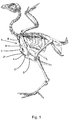
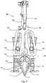
- Fig. 1 illustrates schematically the skeleton of a chicken and the cut that is made by the primary wishbone cutter the cut that is made by the primary wishbone cutter.
- Wishbone 1 comprises a tip, which in scientific terms is known as the hypocledium 2, and two limbs 3 (only one of them shown in fig. 1 as fig. 1 is a side view).
- the hypocledium 2 comprises an inward facing surface 2*.
- Fig. 1 also illustrates schematically the breastbone (sternum) 5 and the tip of the breastbone, which in scientific terms is known as the carinal apex 5* of the sternum 5. Between the carinal apex 5* of the sternum 5 and the hypocledum 2, hypocledial ligament 4 extends.
- Dashed line 6 in fig. 1 indicates that trajectory that is followed by the primary cutter relative to the poultry carcass.
- Fig. 1 shows that the primary wishbone cutter cuts through the limbs 3 of the wishbone 1 and separates the inward facing surface 2* of the hypocledium 2 from the meat adjacent to it.
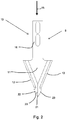
- Fig. 2 schematically illustrates a first embodiment of a primary wishbone cutter 8 according to the invention.
- the primary wishbone cutter 8 comprises a primary wishbone knife 10.
- the primary wishbone knife 10 is moveable in cutting direction 15. It comprises a mounting element 16 which allows it to be mounted in the wishbone separator device according to the invention.
- the primary wishbone knife 10 comprises a front cutter portion 20.
- the front cutter portion 20 has substantially triangular shape and is adapted to separate the hypocledium 2 from meat that is present adjacent to the inward facing surface 2* of the hypocledium 2.
- the front cutter portion 20 comprises a central front apex 21 that points in the cutting direction 15.
- the central front apex 21 is tapered or rounded, but this is not necessary.
- the front cutter portion 20 further comprises a left front cutting edge 22 and a right front cutting edge 23. As can be seen in fig. 2 , the left front cutting edge 22 and the right front cutting edge 23 diverge from the central front apex 21. The left front cutting edge 22 and the right front cutting edge 23 have a straight part in this embodiment.
- the primary wishbone knife 10 further comprises a wishbone limb cutter portion 11.
- the wishbone limb cutter portion 11 has substantially triangular shape and is adapted to cut through the limbs 3 of the wishbone 1.
- the wishbone limb cutter portion 11 comprises a left limb cutting edge 12 and a right limb cutting edge 13, which in this embodiment are straight cutting edges.
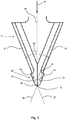
- Fig. 3 shows the front cutter portion 20 and the wishbone limb cutter portion 11 of the embodiment of fig. 2 in more detail.
- Fig. 3 shows imaginary center line 25 that extends in forward and rearward direction parallel to the cutting direction 15 through the central front apex 21 of the front cutter portion 20.
- Fig. 3 also shows imaginary extension line 27 of the left limb cutting edge 12 and imaginary extension line 28 of the right limb cutting edge 13, and the intersection point 29 of the imaginary extension line 27 and the imaginary extension line 28, which is on the center line 25.
- the intersection point 29 almost coincides with the central front apex 21, but this is not necessary.
- Fig. 3 shows that the left front cutting edge 22 is arranged forward of the left limb cutting edge 12 as seen in the cutting direction 15 and outward relative to the imaginary extension line 27 from the left limb cutting edge 22, "outward" being indicated by arrow 19 and meaning away from the area between the parts of imaginary cutting lines 27, 28 between the left and right limb cutting edge 12,13 and the intersection point 29.
- Fig. 3 also shows that the right front cutting edge 23 is arranged forward of the right limb cutting edge 13 as seen in the cutting direction 15 and outward relative to the imaginary extension line 28 from the right limb cutting edge 13, "outward" being indicated by arrow 19 and meaning away from the area between the parts of imaginary cutting lines 27, 28 between the left and right limb cutting edge 12,13 and the intersection point 29.
- Fig. 3 also shows that the left front cutting edge 22 and the right front cutting edge 23 enclose a front cutting angle 31 and the left limb cutting edge 12 and the right limb cutting edge 13 enclose a limb cutting angle 30, wherein the front cutting angle 31 is larger than or equal to the limb cutting angle 30.
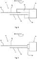
- Fig. 4 shows a second embodiment of a primary wishbone cutter 8 in accordance with the invention. Arrow 15 again indicates the cutting direction.
- the primary wishbone cutter 8 comprises a front cutter knife 35 which comprises the front cutter portion 20 of the primary wishbone cutter 8 and a wishbone limb cutter knife 37 which comprises the wishbone limb cutter portion 11 of the primary wishbone cutter 8.
- the embodiment of fig. 4 further comprises a wishbone cutter actuator 34.
- the wishbone cutter actuator 34 comprises a front cutter knife driver 36 and a wishbone limb cutter knife driver 38, which optionally can be operated independently from one another.
- Fig. 5 shows a variant of the embodiment of fig. 4 .
- the primary wishbone cutter 8 comprises a front cutter knife 35 which comprises the front cutter portion 20 of the primary wishbone cutter 8 and a wishbone limb cutter knife 37 which comprises the wishbone limb cutter portion 11 of the primary wishbone cutter 8.
- the embodiment of fig. 5 further comprises a wishbone cutter actuator 34.
- the wishbone cutter actuator 34 comprises a single primary wishbone cutter driver 39 which is adapted to move the front cutter knife 35 as well as the wishbone limb cutter knife 37.
- Fig. 6 shows an embodiment of a system for separating the wishbone from a poultry carcass, which comprises a device 60.
- the device 60 can be a device according to the invention, a device according to the alternative embodiment not being part of the invention, or a device in which the invention and the alternative embodiment not being part of the invention are combined.
- the wishbone separator system as shown in fig. 6 comprises a poultry carcass conveyor system, which comprises a plurality of product carriers 51 that are adapted to receive a poultry carcass 52, which carriers are moveable along a track 50.
- the device 60 according to the invention is in this system arranged along said track 50.
- other types of processing devices e.g. a device for harvesting breast meat and/or a device for harvesting back meat, are arranged along the track 50 as well.
- a plurality of devices 60 according to the invention is arranged in a carrousel 55.
- the carrousel 55 of fig. 6 comprises a workstation frame 56 that is rotatable about a central axis 57.
- the devices 60 according to the invention are to the rotatable workstation frame 56, so that they rotate with this workstation frame 56 about the central axis 57.
- the carrousel 55 is arranged along the track 50 of the poultry carcass conveyor system, and the track 50 extends along a part of the circumference of the carrousel 55.
- the conveying speed at which the poultry carcass conveyor system moves the poultry carcass 52 (which are held by the carriers 51) along the track 50 and the rotational speed of the carrousel 55 are matched with each other, so that a poultry carcass 52 does not move relative to the device 60 according to the invention that is mounted to the workstation frame 56 and that processes said poultry carcass 52, at least of a part of the length of the track 50 that extends along the circumference of the carrousel 50.
- Fig. 7 and fig. 8 illustrate the method according to the invention in comparison with the prior art.
- Fig. 7 and 8 schematically show the wishbone 1 with the hypocledium 2, the two limbs 3 and the hypocledial ligament 4 that is attached to the hypocledium 2.
- Arrow 15 again indicates the cutting direction.
- Fig. 7 illustrates the known method for separating the wishbone from a poultry carcass using a primary wishbone knife 9, as is for example known from WO2011/068402 and EP1430780A1 .
- Fig. 7A shows the situation in which the known primary wishbone knife 9 has entered the poultry carcass, usually via the neck opening.
- the limbs 3 of the wishbone 1 are cut through before the front tip of the known primary wishbone knife 9 reaches the inward facing surface 2* of the hypocledium 2.
- the known primary wishbone knife 9 has still quite a long way to travel into the poultry carcass before it reaches the point where it can separate the hypocledium from the meat adjacent to the inward facing surface of the hypocledium 2.
- Fig. 7B shows the moment in which the known primary wishbone knife 9 has reached the point where it has separated the hypocledium from the meat adjacent to the inward facing surface of the hypocledium 2.
- Fig. 8 illustrates an embodiment of the method according to the invention, in which a device according to the invention is used. Arrow 15 again indicates the cutting direction.
- Fig. 8A shows that by using a device according to the invention that comprises a primary wishbone cutter 8 in accordance with the invention, the hypocledium can be separated from the meat adjacent to the inward facing surface of the hypocledium 2 by the primary wishbone cutter 8 before the limbs 3 of the wishbone 1 are cut through.
- Fig. 8B shows the moment at which the limbs 3 of the wishbone 1 are cut through.
- Cutting the limbs 3 of the wishbone 1 through after separating the hypocledium from the meat adjacent to the inward facing surface of the hypocledium 2 has the advantage that the wishbone 1 is still generally in its natural position within the poultry carcass, which increases the accuracy of the action of separating the hypocledium from the meat that is present adjacent to the inward facing surface of the hypocledium.
- Fig. 9 shows a possible embodiment of a device 100 in which the invention and the alternative embodiment have been combined, in perspective view.
- Fig. 9 clearly shows the presence of primary wishbone cutter 8 according to the invention, here embodied in the form a primary wishbone knife 10.
- the device 100 comprises a device frame 101 onto which the components of the device 100 are mounted.
- the device 100 further comprises a secondary wishbone cutter 110.
- the secondary wishbone cutter 110 comprises two secondary wishbone knives 111, each adapted for separating the wishbone 1 from meat that is present on the outside of a limb 3 of the wishbone 1.
- the secondary wishbone cutter 110 further comprises a secondary wishbone knives actuator assembly 120.
- the secondary wishbone knives actuator assembly 120 is adapted to prescribe a secondary cutting path for each of the secondary wishbone knives 111 relative to the poultry carcass.
- Each of the secondary cutting paths extends between a first position, in which the respective secondary wishbone knife 111 is outside the poultry carcass and a second position, in which the respective secondary wishbone knife 111 is arranged inside the poultry carcass, adjacent to the wishbone 1 and outside of the limb 3 of the wishbone 1.
- Fig. 9 shows the secondary wishbone knives 111 in their second position.
- the primary wishbone cutter 8 is moveable between a first position outside the poultry carcass and a second position in which the front cutter portion and the wishbone limb cutter portion are inside the poultry carcass.
- the direction of movement from the first position to the second position is the cutting direction 15.
- the front cutter portion and the wishbone limb cutter portion are adapted to be introduced into the poultry carcass via the neck opening.
- Fig. 9 shows the primary wishbone cutter 10 in its second position.
- the secondary wishbone knives actuator assembly 120 comprises two cams track 121, 122. Each cam track 121, 122 is associated with a secondary wishbone knife 111. Each secondary wishbone knife has a cam follower 124, which is moveable through the respective cam track 121, 122.
- the primary wishbone cutter 8 and the secondary wishbone knives 111 are mounted on a moveable mounting block 123.
- the secondary wishbone knives actuator assembly 120 is adapted to move said mounting block 123 relative to the frame 101 when the secondary wishbone knives 111 are moved from their respective first position to their respective second position or vice versa.
- a cylinder 125 e.g. a pneumatic cylinder, is provided to effect this movement.
- the primary wishbone cutter 8 is also mounted onto the mounting block 123.
- the mounting block 123 moves both the primary wishbone cutter 8 and the secondary wishbone knives 111 relative to the frame 101 of the device 100, and during operation, relative to the poultry carcass.
- the secondary wishbone knives 111 are pivotably mounted to the mounting block 123.
- the secondary wishbone knives actuator assembly 120 is adapted to move the mounting block 123 relative to the cam tracks 121, 122 when the secondary wishbone knives 111 are moved from their respective first position to their respective second position or vice versa.
- the cam tracks 121, 122 are only in one way moveable relative to the frame 101, which is by pivoting around pivot 130, which is part of the system for switching from the small carcass mode to the large carcass mode or vice versa. So, when cylinder 125 moves the mounting block 123 with the primary wishbone cutter 8 and the secondary wishbone knifes 111 in the cutting direction 15, the cam tracks 121, 122 remain stationary relative to the device frame 101. This causes a relative movement of the cam followers 124 in the cam tracks 121, 122, which in turn causes the secondary wishbone knives 11 to pivot relative to the mounting block 123.
- the combined motion that is prescribed to the secondary wishbone knives 111 i.e. the movement in the cutting direction by the cylinder 125 and the pivoting by the cam tracks 121, 122) results in curved secondary cutting paths for the secondary wishbone knives 111.
- the secondary wishbone knives actuator assembly 110 has a small carcass mode and a large carcass mode.
- the secondary cutting path that is prescribed when the secondary wishbone knives actuator assembly 110 is in the small carcass mode differs from the secondary cutting path that is prescribed when the secondary wishbone knives actuator assembly 110 is in the large carcass mode.
- this feature is obtained by allowing the cam tracks 121, 122 to assume two different positions relative to the device frame 101, one position being associated with the small carcass mode and the other position being associated with the large carcass mode.
- cam tracks 121, 122 are pivotable relative to the frame 101 about pivot 130.
- a cam track adjuster 131 has been provided, which in this embodiment is a cylinder, e.g. a pneumatic cylinder.
- the cylinder comprises a cylinder head 133.
- the cylinder head comprises a pin which extends through adjustment slots 132, which are provided in the same bodies that also contain one of the cam tracks 121, 122.
- the position of the cam track adjuster 131 i.e. cylinder extended or retracted
- the pin of the cylinder head 133 moves through the adjustment slots, and therewith, the cam tracks 121, 122 are rotated about pivot 130 relative to the device frame 101.
- the cam track adjuster maintains its extended or retracted position, so switching between the small carcass mode and the large carcass mode only occurs during idle time of the wishbone separator device 100.
- Fig. 10 shows the embodiment of fig. 9 , in front view, with the primary wishbone cutter 8 and the secondary wishbone knives 111 in their respective first positions and the secondary wishbone knives actuator assembly 120 in the large carcass mode.
- the wishbone separator device is in this position at the start of the wishbone separating process, when the next poultry carcass to be processed is classified as being in the range "large” or "intermediate".
- the mounting block 123 is in its high position relative to the device frame 101, and therewith the primary wishbone knife 10 and the secondary wishbone knives 111 are in their respective first positions.
- the cam followers 124 are at the top end of the cam tracks 121, 122. If a poultry carcass is arranged at the device 100, the primary wishbone knife 8 and the secondary wishbone knives 111 are arranged outside the poultry carcass.
- the secondary wishbone knives actuator assembly is in the large carcass mode, which in this embodiment involves that the upper parts of the cam tracks 121, 122 are relatively far away from one another.
- the cylinder of the cam track adjuster 131 is in its extended position, and the pin in the cylinder head 133 is in the lower part of the adjustment slots 132.
- Fig. 11 shows the embodiment of fig. 9 , in front view, with the primary wishbone cutter 8 and the secondary wishbone knives 111 in their respective second positions and the secondary wishbone knives actuator assembly 120 in the large carcass mode.
- the wishbone separator device is in this position just after cutting through the limbs of the wishbone, separating the hypocledium from the meat adjacent to the inward facing surface of the hypocledium and separating the meat from the outside of the limbs of the wishbone (and optionally severing the hypocledial ligament), but before the wishbone is actually removed from the poultry carcass.
- the poultry carcass that is processed is classified as being in the range "large” or "intermediate".
- the mounting block 123 is in its low position relative to the device frame 101, and therewith the primary wishbone knife 10 and the secondary wishbone knives 111 are in their respective second positions.
- Moving the mounting block 123 relative to the device frame 101 can for example be achieved by means of providing the secondary wishbone knives actuator assembly with a cam track (which is e.g. mounted stationary around the central axis of a carrousel) and a cam follower that is connected to the mounting block and which runs in this cam track.
- the cam followers 124 of the secondary wishbone knives 111 are near the bottom end of the cam tracks 121, 122. If a poultry carcass is arranged at the device 100, the primary wishbone knife 8 and the secondary wishbone knives 111 are arranged inside the poultry carcass, the primary wishbone knife 10 at least to such an extent that the front cutter portion and the wishbone limb cutting portion are inside the poultry carcass.
- the secondary wishbone knives actuator assembly is still in the small carcass mode.
- the cylinder of the cam track adjuster 131 has not been actuated.
- Fig. 12 shows the embodiment of fig. 9 , in front view, with the primary wishbone cutter 8 and the secondary wishbone knives 111 in their respective first positions and the secondary wishbone knives actuator assembly 120 in the small carcass mode.
- the wishbone separator device is in this position at the start of the wishbone separating process, when the next poultry carcass to be processed is classified as being in the range "small” or "intermediate".
- the mounting block 123 is in its high position relative to the device frame 101, and therewith the primary wishbone knife 10 and the secondary wishbone knives 111 are in their respective first positions.
- the cam followers 124 are at the top end of the cam tracks 121, 122. If a poultry carcass is arranged at the device 100, the primary wishbone knife 8 and the secondary wishbone knives 111 are arranged outside the poultry carcass.
- the secondary wishbone knives actuator assembly 120 is in the small carcass mode, which in this embodiment involves that the upper parts of the cam tracks 121, 122 are relatively close from one another.
- the cylinder of the cam track adjuster 131 is in its retracted position, and the pin in the cylinder head 133 is in the upper part of the adjustment slots 132.
- the secondary wishbone knives actuator assembly 120 can be shifted from the large carcass mode to the small carcass mode and vice versa by actuating the cylinder of the cam track adjuster 131.
- the pin of the cylinder head 133 moves through the adjustment slots, and therewith, the cam tracks 121, 122 are rotated about pivot 130 relative to the device frame 101 from the small carcass mode to the large carcass mode or vice versa.
Landscapes
- Life Sciences & Earth Sciences (AREA)
- Engineering & Computer Science (AREA)
- Forests & Forestry (AREA)
- Mechanical Engineering (AREA)
- Wood Science & Technology (AREA)
- Zoology (AREA)
- Food Science & Technology (AREA)
- Processing Of Meat And Fish (AREA)
Priority Applications (3)
| Application Number | Priority Date | Filing Date | Title |
|---|---|---|---|
| DK20156116.4T DK3666078T3 (da) | 2015-07-29 | 2016-07-12 | Anordning til adskillelse af et ønskeben fra en fjerkræslagtekrop |
| PL16750531T PL3328207T3 (pl) | 2015-07-29 | 2016-07-12 | Urządzenie i sposób oddzielania kości widełkowej od tuszy drobiowej |
| EP20156116.4A EP3666078B1 (en) | 2015-07-29 | 2016-07-12 | Device for separating a wishbone from a poultry carcass |
Applications Claiming Priority (2)
| Application Number | Priority Date | Filing Date | Title |
|---|---|---|---|
| NL2015235A NL2015235B1 (en) | 2015-07-29 | 2015-07-29 | Device and method for separating a wishbone from a poultry carcass. |
| PCT/NL2016/050515 WO2017018876A2 (en) | 2015-07-29 | 2016-07-12 | Device and method for separating a wishbone from a poultry carcass |
Related Child Applications (2)
| Application Number | Title | Priority Date | Filing Date |
|---|---|---|---|
| EP20156116.4A Division-Into EP3666078B1 (en) | 2015-07-29 | 2016-07-12 | Device for separating a wishbone from a poultry carcass |
| EP20156116.4A Division EP3666078B1 (en) | 2015-07-29 | 2016-07-12 | Device for separating a wishbone from a poultry carcass |
Publications (2)
| Publication Number | Publication Date |
|---|---|
| EP3328207A2 EP3328207A2 (en) | 2018-06-06 |
| EP3328207B1 true EP3328207B1 (en) | 2020-03-18 |
Family
ID=55273450
Family Applications (2)
| Application Number | Title | Priority Date | Filing Date |
|---|---|---|---|
| EP16750531.2A Active EP3328207B1 (en) | 2015-07-29 | 2016-07-12 | Device and method for separating a wishbone from a poultry carcass |
| EP20156116.4A Active EP3666078B1 (en) | 2015-07-29 | 2016-07-12 | Device for separating a wishbone from a poultry carcass |
Family Applications After (1)
| Application Number | Title | Priority Date | Filing Date |
|---|---|---|---|
| EP20156116.4A Active EP3666078B1 (en) | 2015-07-29 | 2016-07-12 | Device for separating a wishbone from a poultry carcass |
Country Status (10)
| Country | Link |
|---|---|
| US (1) | US10130106B2 (enExample) |
| EP (2) | EP3328207B1 (enExample) |
| JP (1) | JP6927958B2 (enExample) |
| KR (1) | KR102606668B1 (enExample) |
| CN (1) | CN107846911B (enExample) |
| BR (1) | BR112017027619A2 (enExample) |
| DK (2) | DK3666078T3 (enExample) |
| NL (1) | NL2015235B1 (enExample) |
| PL (1) | PL3328207T3 (enExample) |
| WO (1) | WO2017018876A2 (enExample) |
Families Citing this family (4)
| Publication number | Priority date | Publication date | Assignee | Title |
|---|---|---|---|---|
| PL3692797T3 (pl) * | 2019-02-11 | 2025-01-27 | Nordischer Maschinenbau Rud. Baader Gmbh + Co. Kg | Urządzenie i sposób automatycznego pozyskiwania filetów z piersi z tusz drobiowych lub ich części |
| CN115397246B (zh) * | 2020-07-01 | 2023-10-03 | 北欧机械制造鲁道夫巴德尔有限及两合公司 | 沿线移动工具安置的设备和方法和叉骨去除的组件和方法 |
| CN113103312B (zh) * | 2021-04-22 | 2022-12-06 | 陕西紫熙农业综合开发有限公司 | 一种食品自动化切片设备 |
| NL2028907B1 (en) * | 2021-08-03 | 2023-02-17 | Meyn Food Processing Tech Bv | Method and device for processing a carcass-part of slaughtered poultry |
Family Cites Families (13)
| Publication number | Priority date | Publication date | Assignee | Title |
|---|---|---|---|---|
| DE3811317A1 (de) * | 1988-04-02 | 1989-10-19 | Nordischer Maschinenbau | Verfahren zum gewinnen des fleisches von den koerpern geschlachteten gefluegels und vorrichtung zur durchfuehrung des verfahrens |
| DE4413683C2 (de) * | 1994-04-20 | 1996-07-04 | Nordischer Maschinenbau | Einrichtung zum Bearbeiten der Körper geschlachteten Geflügels |
| NL9401198A (nl) * | 1994-07-21 | 1996-03-01 | Stork Pmt | Werkwijze en inrichting voor het fileren van de romp van geslacht gevogelte. |
| JP3960699B2 (ja) | 1998-01-21 | 2007-08-15 | 株式会社前川製作所 | 鶏肉屠体上半身の脱骨自動処理方法とその装置 |
| ES2610405T3 (es) * | 2002-12-20 | 2017-04-27 | Marel Stork Poultry Processing B.V. | Procedimiento y dispositivo de tratamiento de una pieza de carcasa de ave de corral sacrificada |
| NL1022858C2 (nl) * | 2003-03-06 | 2004-09-16 | Meyn Food Proc Technology Bv | Fileerstraat voor gevogelte. |
| EP2353396B1 (en) | 2005-12-09 | 2020-12-02 | Marel Stork Poultry Processing B.V. | Method and device for processing a carcass part of slaughtered poultry |
| NL2003384C2 (en) * | 2009-08-24 | 2011-02-28 | Meijn Food Proc Technology B V | Method and device for processing a carcass-part of slaughtered poultry. |
| NL2003900C2 (en) * | 2009-12-03 | 2011-06-06 | Stork P M T B V | Device and method for processing a carcass part of slaughtered poultry. |
| DE102011107067B3 (de) | 2011-07-11 | 2012-12-20 | Nordischer Maschinenbau Rud. Baader Gmbh + Co Kg | Vorrichtung und Verfahren zum Abtrennen des Gabelbeins von entweideten Geflügelkörpern |
| NL2008021C2 (en) * | 2011-12-22 | 2013-06-26 | Meyn Food Proc Technology Bv | Method and device for processing a carcass part of slaughtered poultry. |
| US8535124B1 (en) * | 2012-10-17 | 2013-09-17 | Remington Holdings Llc | Poultry tender tendon clipper |
| NL2015436B1 (en) * | 2015-09-14 | 2017-04-19 | Foodmate Bv | Apparatus, system and method for removing furculae from poultry breast caps. |
-
2015
- 2015-07-29 NL NL2015235A patent/NL2015235B1/en not_active IP Right Cessation
-
2016
- 2016-07-12 US US15/740,187 patent/US10130106B2/en active Active
- 2016-07-12 EP EP16750531.2A patent/EP3328207B1/en active Active
- 2016-07-12 BR BR112017027619-4A patent/BR112017027619A2/pt not_active Application Discontinuation
- 2016-07-12 DK DK20156116.4T patent/DK3666078T3/da active
- 2016-07-12 CN CN201680043666.2A patent/CN107846911B/zh active Active
- 2016-07-12 WO PCT/NL2016/050515 patent/WO2017018876A2/en not_active Ceased
- 2016-07-12 DK DK16750531.2T patent/DK3328207T3/da active
- 2016-07-12 KR KR1020187003431A patent/KR102606668B1/ko active Active
- 2016-07-12 EP EP20156116.4A patent/EP3666078B1/en active Active
- 2016-07-12 PL PL16750531T patent/PL3328207T3/pl unknown
- 2016-07-12 JP JP2018504196A patent/JP6927958B2/ja active Active
Non-Patent Citations (1)
| Title |
|---|
| None * |
Also Published As
| Publication number | Publication date |
|---|---|
| KR102606668B1 (ko) | 2023-11-28 |
| NL2015235B1 (en) | 2017-02-20 |
| CN107846911A (zh) | 2018-03-27 |
| JP6927958B2 (ja) | 2021-09-01 |
| EP3328207A2 (en) | 2018-06-06 |
| WO2017018876A3 (en) | 2017-03-16 |
| US10130106B2 (en) | 2018-11-20 |
| WO2017018876A2 (en) | 2017-02-02 |
| BR112017027619A2 (pt) | 2018-08-28 |
| CN107846911B (zh) | 2020-07-03 |
| DK3666078T3 (da) | 2024-03-11 |
| DK3328207T3 (da) | 2020-06-15 |
| JP2018525984A (ja) | 2018-09-13 |
| EP3666078A1 (en) | 2020-06-17 |
| KR20180033511A (ko) | 2018-04-03 |
| US20180184673A1 (en) | 2018-07-05 |
| PL3328207T3 (pl) | 2020-10-19 |
| EP3666078B1 (en) | 2023-12-20 |
Similar Documents
| Publication | Publication Date | Title |
|---|---|---|
| EP3328207B1 (en) | Device and method for separating a wishbone from a poultry carcass | |
| EP3157343B1 (en) | Method and system for harvesting knee meat together with thigh meat from a poultry leg | |
| US8500522B2 (en) | Device and method for processing a carcass part of slaughtered poultry | |
| EP2384643B1 (en) | A method for filleting poultry or poultry parts as well as filleting system and cutting instrument for such poultry or poultry parts | |
| DK2656736T3 (en) | Method and apparatus for machining a poultry body part | |
| US11679509B2 (en) | Portioning device and a method for packaging of food products | |
| US20170006883A1 (en) | Positioning device for positioning poultry legs conveyed in single file in the conveying direction along a conveyor section and the method comprising said positioning for removing the thigh meat from poultry legs | |
| CN105120673B (zh) | 在传送路径的传送方向t上以尾部朝前方式被传送的去头且至少被取出内脏的鱼的机械加工装置及加工方法 | |
| US9220283B2 (en) | Device and method for completely separating from the carcass of a gutted poultry body breast fillets that have already been partially detached from the carcass | |
| AU672462B2 (en) | Method for detaching the wings from poultry bodies and an apparatus for carrying out the method | |
| EP3432724B1 (en) | System for separating breast meat from at least a part of a keel bone of a carcass part of slaughtered poultry | |
| US20230042295A1 (en) | Method and device for processing a carcass-part of slaughtered poultry | |
| JP2018525984A5 (enExample) | ||
| US11925185B2 (en) | Apparatus and method for cutting into breast fillets that are connected to one another at least in the region of a breastbone of a carcass of poultry bodies or parts thereof, wherein the breast fillets are cut along the breastbone |
Legal Events
| Date | Code | Title | Description |
|---|---|---|---|
| STAA | Information on the status of an ep patent application or granted ep patent |
Free format text: STATUS: THE INTERNATIONAL PUBLICATION HAS BEEN MADE |
|
| PUAI | Public reference made under article 153(3) epc to a published international application that has entered the european phase |
Free format text: ORIGINAL CODE: 0009012 |
|
| STAA | Information on the status of an ep patent application or granted ep patent |
Free format text: STATUS: REQUEST FOR EXAMINATION WAS MADE |
|
| 17P | Request for examination filed |
Effective date: 20180226 |
|
| AK | Designated contracting states |
Kind code of ref document: A2 Designated state(s): AL AT BE BG CH CY CZ DE DK EE ES FI FR GB GR HR HU IE IS IT LI LT LU LV MC MK MT NL NO PL PT RO RS SE SI SK SM TR |
|
| AX | Request for extension of the european patent |
Extension state: BA ME |
|
| DAV | Request for validation of the european patent (deleted) | ||
| DAX | Request for extension of the european patent (deleted) | ||
| GRAP | Despatch of communication of intention to grant a patent |
Free format text: ORIGINAL CODE: EPIDOSNIGR1 |
|
| STAA | Information on the status of an ep patent application or granted ep patent |
Free format text: STATUS: GRANT OF PATENT IS INTENDED |
|
| RIC1 | Information provided on ipc code assigned before grant |
Ipc: B26D 5/12 20060101ALI20190415BHEP Ipc: A22C 21/00 20060101AFI20190415BHEP Ipc: B26D 7/06 20060101ALI20190415BHEP Ipc: B26D 1/00 20060101ALI20190415BHEP Ipc: B26D 1/04 20060101ALI20190415BHEP |
|
| INTG | Intention to grant announced |
Effective date: 20190522 |
|
| GRAJ | Information related to disapproval of communication of intention to grant by the applicant or resumption of examination proceedings by the epo deleted |
Free format text: ORIGINAL CODE: EPIDOSDIGR1 |
|
| STAA | Information on the status of an ep patent application or granted ep patent |
Free format text: STATUS: REQUEST FOR EXAMINATION WAS MADE |
|
| GRAP | Despatch of communication of intention to grant a patent |
Free format text: ORIGINAL CODE: EPIDOSNIGR1 |
|
| STAA | Information on the status of an ep patent application or granted ep patent |
Free format text: STATUS: GRANT OF PATENT IS INTENDED |
|
| INTC | Intention to grant announced (deleted) | ||
| INTG | Intention to grant announced |
Effective date: 20191009 |
|
| GRAS | Grant fee paid |
Free format text: ORIGINAL CODE: EPIDOSNIGR3 |
|
| GRAA | (expected) grant |
Free format text: ORIGINAL CODE: 0009210 |
|
| STAA | Information on the status of an ep patent application or granted ep patent |
Free format text: STATUS: THE PATENT HAS BEEN GRANTED |
|
| AK | Designated contracting states |
Kind code of ref document: B1 Designated state(s): AL AT BE BG CH CY CZ DE DK EE ES FI FR GB GR HR HU IE IS IT LI LT LU LV MC MK MT NL NO PL PT RO RS SE SI SK SM TR |
|
| REG | Reference to a national code |
Ref country code: GB Ref legal event code: FG4D |
|
| REG | Reference to a national code |
Ref country code: DE Ref legal event code: R096 Ref document number: 602016032076 Country of ref document: DE |
|
| REG | Reference to a national code |
Ref country code: AT Ref legal event code: REF Ref document number: 1244859 Country of ref document: AT Kind code of ref document: T Effective date: 20200415 Ref country code: IE Ref legal event code: FG4D |
|
| REG | Reference to a national code |
Ref country code: DK Ref legal event code: T3 Effective date: 20200608 |
|
| REG | Reference to a national code |
Ref country code: NL Ref legal event code: FP |
|
| PG25 | Lapsed in a contracting state [announced via postgrant information from national office to epo] |
Ref country code: RS Free format text: LAPSE BECAUSE OF FAILURE TO SUBMIT A TRANSLATION OF THE DESCRIPTION OR TO PAY THE FEE WITHIN THE PRESCRIBED TIME-LIMIT Effective date: 20200318 Ref country code: FI Free format text: LAPSE BECAUSE OF FAILURE TO SUBMIT A TRANSLATION OF THE DESCRIPTION OR TO PAY THE FEE WITHIN THE PRESCRIBED TIME-LIMIT Effective date: 20200318 Ref country code: NO Free format text: LAPSE BECAUSE OF FAILURE TO SUBMIT A TRANSLATION OF THE DESCRIPTION OR TO PAY THE FEE WITHIN THE PRESCRIBED TIME-LIMIT Effective date: 20200618 |
|
| PG25 | Lapsed in a contracting state [announced via postgrant information from national office to epo] |
Ref country code: GR Free format text: LAPSE BECAUSE OF FAILURE TO SUBMIT A TRANSLATION OF THE DESCRIPTION OR TO PAY THE FEE WITHIN THE PRESCRIBED TIME-LIMIT Effective date: 20200619 Ref country code: BG Free format text: LAPSE BECAUSE OF FAILURE TO SUBMIT A TRANSLATION OF THE DESCRIPTION OR TO PAY THE FEE WITHIN THE PRESCRIBED TIME-LIMIT Effective date: 20200618 Ref country code: SE Free format text: LAPSE BECAUSE OF FAILURE TO SUBMIT A TRANSLATION OF THE DESCRIPTION OR TO PAY THE FEE WITHIN THE PRESCRIBED TIME-LIMIT Effective date: 20200318 Ref country code: LV Free format text: LAPSE BECAUSE OF FAILURE TO SUBMIT A TRANSLATION OF THE DESCRIPTION OR TO PAY THE FEE WITHIN THE PRESCRIBED TIME-LIMIT Effective date: 20200318 Ref country code: HR Free format text: LAPSE BECAUSE OF FAILURE TO SUBMIT A TRANSLATION OF THE DESCRIPTION OR TO PAY THE FEE WITHIN THE PRESCRIBED TIME-LIMIT Effective date: 20200318 |
|
| REG | Reference to a national code |
Ref country code: LT Ref legal event code: MG4D |
|
| PG25 | Lapsed in a contracting state [announced via postgrant information from national office to epo] |
Ref country code: SM Free format text: LAPSE BECAUSE OF FAILURE TO SUBMIT A TRANSLATION OF THE DESCRIPTION OR TO PAY THE FEE WITHIN THE PRESCRIBED TIME-LIMIT Effective date: 20200318 Ref country code: EE Free format text: LAPSE BECAUSE OF FAILURE TO SUBMIT A TRANSLATION OF THE DESCRIPTION OR TO PAY THE FEE WITHIN THE PRESCRIBED TIME-LIMIT Effective date: 20200318 Ref country code: PT Free format text: LAPSE BECAUSE OF FAILURE TO SUBMIT A TRANSLATION OF THE DESCRIPTION OR TO PAY THE FEE WITHIN THE PRESCRIBED TIME-LIMIT Effective date: 20200812 Ref country code: SK Free format text: LAPSE BECAUSE OF FAILURE TO SUBMIT A TRANSLATION OF THE DESCRIPTION OR TO PAY THE FEE WITHIN THE PRESCRIBED TIME-LIMIT Effective date: 20200318 Ref country code: IS Free format text: LAPSE BECAUSE OF FAILURE TO SUBMIT A TRANSLATION OF THE DESCRIPTION OR TO PAY THE FEE WITHIN THE PRESCRIBED TIME-LIMIT Effective date: 20200718 Ref country code: RO Free format text: LAPSE BECAUSE OF FAILURE TO SUBMIT A TRANSLATION OF THE DESCRIPTION OR TO PAY THE FEE WITHIN THE PRESCRIBED TIME-LIMIT Effective date: 20200318 Ref country code: CZ Free format text: LAPSE BECAUSE OF FAILURE TO SUBMIT A TRANSLATION OF THE DESCRIPTION OR TO PAY THE FEE WITHIN THE PRESCRIBED TIME-LIMIT Effective date: 20200318 Ref country code: LT Free format text: LAPSE BECAUSE OF FAILURE TO SUBMIT A TRANSLATION OF THE DESCRIPTION OR TO PAY THE FEE WITHIN THE PRESCRIBED TIME-LIMIT Effective date: 20200318 |
|
| REG | Reference to a national code |
Ref country code: AT Ref legal event code: MK05 Ref document number: 1244859 Country of ref document: AT Kind code of ref document: T Effective date: 20200318 |
|
| REG | Reference to a national code |
Ref country code: DE Ref legal event code: R097 Ref document number: 602016032076 Country of ref document: DE |
|
| PLBE | No opposition filed within time limit |
Free format text: ORIGINAL CODE: 0009261 |
|
| STAA | Information on the status of an ep patent application or granted ep patent |
Free format text: STATUS: NO OPPOSITION FILED WITHIN TIME LIMIT |
|
| PG25 | Lapsed in a contracting state [announced via postgrant information from national office to epo] |
Ref country code: AT Free format text: LAPSE BECAUSE OF FAILURE TO SUBMIT A TRANSLATION OF THE DESCRIPTION OR TO PAY THE FEE WITHIN THE PRESCRIBED TIME-LIMIT Effective date: 20200318 Ref country code: ES Free format text: LAPSE BECAUSE OF FAILURE TO SUBMIT A TRANSLATION OF THE DESCRIPTION OR TO PAY THE FEE WITHIN THE PRESCRIBED TIME-LIMIT Effective date: 20200318 |
|
| 26N | No opposition filed |
Effective date: 20201221 |
|
| PG25 | Lapsed in a contracting state [announced via postgrant information from national office to epo] |
Ref country code: MC Free format text: LAPSE BECAUSE OF FAILURE TO SUBMIT A TRANSLATION OF THE DESCRIPTION OR TO PAY THE FEE WITHIN THE PRESCRIBED TIME-LIMIT Effective date: 20200318 |
|
| REG | Reference to a national code |
Ref country code: CH Ref legal event code: PL |
|
| REG | Reference to a national code |
Ref country code: BE Ref legal event code: MM Effective date: 20200731 |
|
| PG25 | Lapsed in a contracting state [announced via postgrant information from national office to epo] |
Ref country code: CH Free format text: LAPSE BECAUSE OF NON-PAYMENT OF DUE FEES Effective date: 20200731 Ref country code: LU Free format text: LAPSE BECAUSE OF NON-PAYMENT OF DUE FEES Effective date: 20200712 Ref country code: LI Free format text: LAPSE BECAUSE OF NON-PAYMENT OF DUE FEES Effective date: 20200731 |
|
| PG25 | Lapsed in a contracting state [announced via postgrant information from national office to epo] |
Ref country code: BE Free format text: LAPSE BECAUSE OF NON-PAYMENT OF DUE FEES Effective date: 20200731 Ref country code: SI Free format text: LAPSE BECAUSE OF FAILURE TO SUBMIT A TRANSLATION OF THE DESCRIPTION OR TO PAY THE FEE WITHIN THE PRESCRIBED TIME-LIMIT Effective date: 20200318 |
|
| PG25 | Lapsed in a contracting state [announced via postgrant information from national office to epo] |
Ref country code: IE Free format text: LAPSE BECAUSE OF NON-PAYMENT OF DUE FEES Effective date: 20200712 |
|
| PG25 | Lapsed in a contracting state [announced via postgrant information from national office to epo] |
Ref country code: TR Free format text: LAPSE BECAUSE OF FAILURE TO SUBMIT A TRANSLATION OF THE DESCRIPTION OR TO PAY THE FEE WITHIN THE PRESCRIBED TIME-LIMIT Effective date: 20200318 Ref country code: MT Free format text: LAPSE BECAUSE OF FAILURE TO SUBMIT A TRANSLATION OF THE DESCRIPTION OR TO PAY THE FEE WITHIN THE PRESCRIBED TIME-LIMIT Effective date: 20200318 Ref country code: CY Free format text: LAPSE BECAUSE OF FAILURE TO SUBMIT A TRANSLATION OF THE DESCRIPTION OR TO PAY THE FEE WITHIN THE PRESCRIBED TIME-LIMIT Effective date: 20200318 |
|
| PG25 | Lapsed in a contracting state [announced via postgrant information from national office to epo] |
Ref country code: MK Free format text: LAPSE BECAUSE OF FAILURE TO SUBMIT A TRANSLATION OF THE DESCRIPTION OR TO PAY THE FEE WITHIN THE PRESCRIBED TIME-LIMIT Effective date: 20200318 Ref country code: AL Free format text: LAPSE BECAUSE OF FAILURE TO SUBMIT A TRANSLATION OF THE DESCRIPTION OR TO PAY THE FEE WITHIN THE PRESCRIBED TIME-LIMIT Effective date: 20200318 |
|
| P01 | Opt-out of the competence of the unified patent court (upc) registered |
Effective date: 20230514 |
|
| PGFP | Annual fee paid to national office [announced via postgrant information from national office to epo] |
Ref country code: GB Payment date: 20250619 Year of fee payment: 10 Ref country code: DK Payment date: 20250619 Year of fee payment: 10 |
|
| PGFP | Annual fee paid to national office [announced via postgrant information from national office to epo] |
Ref country code: NL Payment date: 20250620 Year of fee payment: 10 |
|
| PGFP | Annual fee paid to national office [announced via postgrant information from national office to epo] |
Ref country code: FR Payment date: 20250620 Year of fee payment: 10 |
|
| PGFP | Annual fee paid to national office [announced via postgrant information from national office to epo] |
Ref country code: DE Payment date: 20250620 Year of fee payment: 10 |
|
| PGFP | Annual fee paid to national office [announced via postgrant information from national office to epo] |
Ref country code: PL Payment date: 20250701 Year of fee payment: 10 Ref country code: IT Payment date: 20250619 Year of fee payment: 10 |