EP3328173A1 - Inverter structure for vehicle - Google Patents
Inverter structure for vehicle Download PDFInfo
- Publication number
- EP3328173A1 EP3328173A1 EP17176574.6A EP17176574A EP3328173A1 EP 3328173 A1 EP3328173 A1 EP 3328173A1 EP 17176574 A EP17176574 A EP 17176574A EP 3328173 A1 EP3328173 A1 EP 3328173A1
- Authority
- EP
- European Patent Office
- Prior art keywords
- power modules
- coolers
- bar
- stacked
- power
- Prior art date
- Legal status (The legal status is an assumption and is not a legal conclusion. Google has not performed a legal analysis and makes no representation as to the accuracy of the status listed.)
- Granted
Links
Images


Classifications
-
- H—ELECTRICITY
- H05—ELECTRIC TECHNIQUES NOT OTHERWISE PROVIDED FOR
- H05K—PRINTED CIRCUITS; CASINGS OR CONSTRUCTIONAL DETAILS OF ELECTRIC APPARATUS; MANUFACTURE OF ASSEMBLAGES OF ELECTRICAL COMPONENTS
- H05K7/00—Constructional details common to different types of electric apparatus
- H05K7/20—Modifications to facilitate cooling, ventilating, or heating
- H05K7/2089—Modifications to facilitate cooling, ventilating, or heating for power electronics, e.g. for inverters for controlling motor
- H05K7/20945—Thermal management, e.g. inverter temperature control
-
- H—ELECTRICITY
- H05—ELECTRIC TECHNIQUES NOT OTHERWISE PROVIDED FOR
- H05K—PRINTED CIRCUITS; CASINGS OR CONSTRUCTIONAL DETAILS OF ELECTRIC APPARATUS; MANUFACTURE OF ASSEMBLAGES OF ELECTRICAL COMPONENTS
- H05K7/00—Constructional details common to different types of electric apparatus
- H05K7/20—Modifications to facilitate cooling, ventilating, or heating
- H05K7/2089—Modifications to facilitate cooling, ventilating, or heating for power electronics, e.g. for inverters for controlling motor
- H05K7/20927—Liquid coolant without phase change
-
- H—ELECTRICITY
- H02—GENERATION; CONVERSION OR DISTRIBUTION OF ELECTRIC POWER
- H02K—DYNAMO-ELECTRIC MACHINES
- H02K11/00—Structural association of dynamo-electric machines with electric components or with devices for shielding, monitoring or protection
- H02K11/30—Structural association with control circuits or drive circuits
- H02K11/33—Drive circuits, e.g. power electronics
-
- H—ELECTRICITY
- H02—GENERATION; CONVERSION OR DISTRIBUTION OF ELECTRIC POWER
- H02K—DYNAMO-ELECTRIC MACHINES
- H02K5/00—Casings; Enclosures; Supports
- H02K5/04—Casings or enclosures characterised by the shape, form or construction thereof
- H02K5/22—Auxiliary parts of casings not covered by groups H02K5/06-H02K5/20, e.g. shaped to form connection boxes or terminal boxes
- H02K5/225—Terminal boxes or connection arrangements
-
- H—ELECTRICITY
- H02—GENERATION; CONVERSION OR DISTRIBUTION OF ELECTRIC POWER
- H02M—APPARATUS FOR CONVERSION BETWEEN AC AND AC, BETWEEN AC AND DC, OR BETWEEN DC AND DC, AND FOR USE WITH MAINS OR SIMILAR POWER SUPPLY SYSTEMS; CONVERSION OF DC OR AC INPUT POWER INTO SURGE OUTPUT POWER; CONTROL OR REGULATION THEREOF
- H02M7/00—Conversion of ac power input into dc power output; Conversion of dc power input into ac power output
- H02M7/003—Constructional details, e.g. physical layout, assembly, wiring or busbar connections
-
- H—ELECTRICITY
- H05—ELECTRIC TECHNIQUES NOT OTHERWISE PROVIDED FOR
- H05K—PRINTED CIRCUITS; CASINGS OR CONSTRUCTIONAL DETAILS OF ELECTRIC APPARATUS; MANUFACTURE OF ASSEMBLAGES OF ELECTRICAL COMPONENTS
- H05K7/00—Constructional details common to different types of electric apparatus
- H05K7/20—Modifications to facilitate cooling, ventilating, or heating
- H05K7/20845—Modifications to facilitate cooling, ventilating, or heating for automotive electronic casings
-
- B—PERFORMING OPERATIONS; TRANSPORTING
- B60—VEHICLES IN GENERAL
- B60Y—INDEXING SCHEME RELATING TO ASPECTS CROSS-CUTTING VEHICLE TECHNOLOGY
- B60Y2200/00—Type of vehicle
- B60Y2200/90—Vehicles comprising electric prime movers
- B60Y2200/92—Hybrid vehicles
-
- B—PERFORMING OPERATIONS; TRANSPORTING
- B60—VEHICLES IN GENERAL
- B60Y—INDEXING SCHEME RELATING TO ASPECTS CROSS-CUTTING VEHICLE TECHNOLOGY
- B60Y2306/00—Other features of vehicle sub-units
- B60Y2306/05—Cooling
-
- B—PERFORMING OPERATIONS; TRANSPORTING
- B60—VEHICLES IN GENERAL
- B60Y—INDEXING SCHEME RELATING TO ASPECTS CROSS-CUTTING VEHICLE TECHNOLOGY
- B60Y2400/00—Special features of vehicle units
- B60Y2400/60—Electric Machines, e.g. motors or generators
- B60Y2400/604—AC Machines, e.g. asynchronous motors
Definitions
- the present disclosure relates to an inverter structure for a vehicle.
- An environmentally friendly vehicle which uses an electric motor as a drive source, such as, for example, a hybrid vehicle or an electric vehicle, generally uses, for example, a high-voltage battery as an energy source for driving the electric motor, and also uses power conversion parts, i.e. an inverter for providing a voltage to the motor and a low DC-DC converter (LDC) for realizing a vehicle voltage of 12 V.
- a high-voltage battery as an energy source for driving the electric motor
- power conversion parts i.e. an inverter for providing a voltage to the motor and a low DC-DC converter (LDC) for realizing a vehicle voltage of 12 V.
- LDC low DC-DC converter
- the inverter is provided between the electric motor and the high-voltage battery to convert the DC voltage of the high-voltage battery into a three-phase AC voltage and provide the same to the motor.
- the main purpose of conventional electric vehicles is short-distance driving and city driving, and thus they usually feature relatively low output models of about 100 kW. That is, the power source of such an electric vehicle is generally a single motor for the front wheels because the electric vehicle does not need a high output, and thus the inverter for supplying current to the motor is also provided to correspond to an output within a relatively small range.
- the inverter which has a planar structure, is configured such that a power module, a capacitor, and an LDC are disposed on the bottom surface of a housing, and a control board is disposed on the upper end thereof.
- a cooling path, along which cooling water flows, is formed below the power module and the LDC, which generate a large amount of heat, in order to inhibit or prevent, for example, deterioration in performance or damage to elements due to excessive heat.
- a general inverter converts current using a single power module, and needs to use a high-output power module or to have an increased number of power modules in order to have increased output. It is difficult to realize high output of a predetermined value due to the properties of a switching element constituting the power module, and thus most inverters adopt the parallel connection of a plurality of power modules in order to deal with high-output specifications. However, because the housing and the cooling path need to be changed when the number of power modules is increased, the existing inverter concept may not be maintained and it is desired to develop a new inverter.
- the present disclosure provides an inverter structure for a vehicle, which may deal with various motor outputs while having a consistent shape because the shape of a cooling path does not need to be changed even when the number of power modules to be applied is changed.
- an inverter structure for a vehicle including a capacitor configured to receive direct current (DC) supplied from a battery, a power module assembly in which power modules of a plurality of power modules are connected to the capacitor to convert the direct current into three-phase alternating current (AC), and coolers of a plurality of coolers are alternately stacked one above another such that each cooler of the plurality of coolers comes into contact at upper and lower surfaces thereof with adjacent power modules of the plurality of power modules for heat transfer therebetween, and an output bus-bar connected to the plurality of power modules configured to output the three-phase alternating current to a motor.
- DC direct current
- AC three-phase alternating current
- the power module assembly may be configured such that the power modules of the plurality of power modules are divided into three columns and are stacked one above another and the coolers of the plurality of coolers are stacked one above another in a column so as to come into contact with the power modules of the plurality of power modules in a horizontal direction.
- the capacitor may include three pairs of P and N terminals, and each pair of the P and N terminals may be connected to the power modules of the plurality of power modules, which are stacked one above another in one column among the three columns of the plurality of power modules, via a DC bus-bar.
- the output bus-bar may be connected, on an individual phase basis, to at least one power module of the plurality of power modules, which are stacked one above another in one column among the three columns of the plurality of power modules, via an AC bus-bar and a current sensor.
- the AC bus-bar may connect two power modules of the plurality of power modules to one end of the current sensor, and the current sensor may include a remaining end connected to the output bus-bar.
- the plurality of power modules may be provided on one side thereof with a plurality of pins, which is connected to a gate board, and the pins of the plurality of pins may be fixed by a bracket.
- the power module assembly may further include an upper surface plate configured to come into contact with an upper surface of an uppermost one of the stacked coolers, a lower surface plate configured to come into contact with a lower surface of a lowermost one of the stacked coolers, and a fixing piece configured to fix the upper surface plate and the lower surface plate to each other.
- the lower surface plate may be provided with a leaf spring configured to apply force upward at a position corresponding to each of the three columns of the plurality of power modules.
- the power module assembly may be provided in one side of a housing, the capacitor may be provided in a lower region of an opposite side of the housing, and the output bus-bar may have one end provided in an upper region of the opposite side of the housing and a remaining end protruding outward from the housing.
- FIG. 1 is a perspective view illustrating the external appearance of an inverter in one form of the present disclosure.
- the inverter is configured to transmit direct current (DC) received from a high voltage battery (not illustrated) to a capacitor provided inside a housing 1, to convert the direct current into three-phase alternating current via a power module connected to the capacitor, and to transmit the alternating current to a motor via an output bus-bar 50.
- DC direct current
- FIG. 2 is a top cross-sectional view of the inverter in one form of the present disclosure.
- the housing 1 is provided with an inlet and an outlet, which are formed in the lower portion of the side surface of the housing 1. Through the inlet and the outlet, the region below a capacitor 10 is subjected to cooling, and cooling water is supplied to a cooler so as to perform the cooling of a power module.
- FIG. 3 is a side cross-sectional view illustrating an inverter structure for a vehicle in one form of the present disclosure
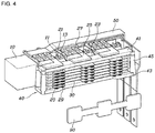
- FIG. 4 is a perspective view illustrating the inverter structure for the vehicle in one form of the present disclosure.
- the inverter structure for the vehicle may include the capacitor 10 for receiving direct current supplied from a battery, a power module assembly 40 in which power modules of a plurality of power modules 20 are connected to the capacitor 10 to convert the direct current into three-phase alternating current, and in which coolers of a plurality of coolers 30 are alternately stacked one above another such that each cooler comes into contact at upper and lower surfaces thereof with the power modules 20 to enable heat transfer therebetween, and the output bus-bar 50 connected to the power modules 20 to output the three-phase alternating current to a motor.
- the power module assembly 40 may perform effective cooling even when the plural power modules 20 are arranged in parallel with one another, and may reduce the volume of an inverter.
- the inverter structure has features by which the power module assembly 40 is provided in one side of the housing 1, the capacitor 10 is provided in the lower region of the opposite side of the housing 1, and the output bus-bar 50 has one end provided in the upper region of the opposite side of the housing 1 and the other end protruding outward from the housing 1.
- the inverter may have a compact internal configuration, and thus the volume of the inverter may be reduced.
- the power module assembly 40 may be configured such that the power modules 20 are stacked one above another in three columns and the coolers 30 are stacked one above another in a column to come into contact with the power modules 20 in the horizontal direction.
- the power modules 20 are provided in three columns, and the power modules 20 of each column respectively convert direct current supplied from the capacitor 10 into alternating current including U, V and W phases, thereby outputting three-phase alternating current.
- the coolers 30 are stacked one above another in a column, unlike the power modules 20, which are stacked in three columns, the coolers 30 may realize cooling of the power modules 20 with a minimum number of elements.
- the power modules 20 may be arranged side by side in the horizontal direction.
- the power module assembly 40 may include a total of eighteen power modules 20, which are arranged in six rows and three columns, and seven coolers 70 may be provided to come into contact with the upper and lower surfaces of the power modules 20.
- FIG. 5 is a perspective view illustrating an inverter structure in which the number of power modules is reduced in one form of the present disclosure.
- an inverter may be configured to correspond to the motor output of approximately 200 kW under the assumption that the power modules 20 are arranged in four rows and three columns.
- an insulation material dummy 60 is mounted at the position at which the existing power module 20 is present, in order to maintain the surface pressure of the power module assembly 40.
- the inverter of the present disclosure may be provided in a manner able to correspond to various motor outputs by changing the number of power modules without changing the configuration of the coolers.
- the merchantability of the inverter may be improved in terms of the common use of parts and the price.
- the capacitor 10 may include three pairs of P and N terminals 11 and 13, and each pair of P and N terminals 11 and 13 may be connected to the power modules, which are stacked one above another in one column among the three columns of the power modules 20, via DC bus-bars 21 and 23.
- FIG. 6 is a cross-sectional view illustrating the connection relationship of the power module assembly in one form of the present disclosure.
- the DC bus-bars 21 and 23 are respectively fitted at one end thereof to a pair of the P terminal 11 and the N terminal 13 formed on the capacitor 10, and the other end is diverged into six portions to thereby be connected to the respective power modules 20 provided in one column.
- the DC bus-bar 21 connected to the P terminal 11 is connected to a positive (+) terminal of the power module and the DC bus-bar 23 connected to the N terminal 13 is connected to a negative (-) terminal of the power module, so as to supply direct current to the power module.
- the output bus-bar 50 may be connected, on an individual phase basis, to the power modules 20, which are stacked one above another in one column among the three columns of the power modules 20, via an AC bus-bar 25 and a current sensor 27.
- the current sensor 27 measures the value of the three-phase alternating current output from the power modules 20.
- a control board (not illustrated) is provided to perform variable control of the performance of the power modules 20 based on the measured three-phase alternating current.
- the AC bus-bar 25 may connect two power modules 20 to one end of the current sensor 27, and the other end of the current sensor 27 may be connected to the output bus-bar 50.
- FIG. 7 is a top plan view illustrating an inverter internal structure in one form of the present disclosure.
- the power modules 20 are provided in six rows and three columns, because each AC bus-bar 25 is connected to two power modules 20 and six power modules 20 are provided in one column, the power modules in each column are connected to three AC-bus-bars 25 and three current sensors 27, which are connected in parallel with one another.
- the entire power module assembly 40 is connected to a total of nine AC bus-bars 25 and nine current sensors 27, and the alternating current output from three current sensors 27 form one phase of the output bus-bar 50.
- the output bus-bars 50 may output three-phase alternating current including U, V and W phases.
- the power modules 20 in one column may be connected to two AC bus-bars 25 and two current sensors 27, which are connected in parallel with one another. At this time, although the number of constituent elements of the inverter is reduced, there is no variation in the internal configuration of the inverter. In this way, an inverter, which may handle various motor outputs, may be easily realized.
- FIG. 8 is a perspective view illustrating the inside of the power module assembly during laser welding in one form of the present disclosure.
- the power modules 20 in three columns may be welded at the same time when the power modules 20, the DC bus-bars 21 and 23, and the AC bus-bars 25 are laser-welded, which may advantageously simplify the manufacturing process.
- a plurality of pins 29, which is connected to a gate board 80 may be formed on one side of the power modules 20, and the pins 29 may be fixed by a bracket 90. That is, when the positions of the pins 29 are fixed using the bracket 90, easy assembly of the pins 29 to the gate board 80 may be achieved.
- the power module assembly 40 may further include an upper surface plate 41, which comes into contact with the upper surface of an uppermost one of the stacked coolers 30, a lower surface plate 43, which comes into contact with the lower surface of a lowermost one of the stacked coolers 30, and fixing pieces 45 for fixing the upper surface plate 41 and the lower surface plate 43 to each other.
- the lower surface plate 43 may be provided with leaf springs, which apply force upward at the positions corresponding to the three columns of the power modules 20. That is, the leaf springs serve to apply surface pressure so that the power modules 20 and the coolers 30 come into close contact with each other.
- the inverter may be capable of providing various motor outputs while maintaining a consistent structural shape thereof, which enables a reduction in cost due to common use of parts.
- the volume of the inverter may be reduced.
Abstract
Description
- The present disclosure relates to an inverter structure for a vehicle.
- The statements in this section merely provide background information related to the present disclosure and may not constitute prior art.
- An environmentally friendly vehicle, which uses an electric motor as a drive source, such as, for example, a hybrid vehicle or an electric vehicle, generally uses, for example, a high-voltage battery as an energy source for driving the electric motor, and also uses power conversion parts, i.e. an inverter for providing a voltage to the motor and a low DC-DC converter (LDC) for realizing a vehicle voltage of 12 V.
- Here, the inverter is provided between the electric motor and the high-voltage battery to convert the DC voltage of the high-voltage battery into a three-phase AC voltage and provide the same to the motor.
- The main purpose of conventional electric vehicles is short-distance driving and city driving, and thus they usually feature relatively low output models of about 100 kW. That is, the power source of such an electric vehicle is generally a single motor for the front wheels because the electric vehicle does not need a high output, and thus the inverter for supplying current to the motor is also provided to correspond to an output within a relatively small range.
- However, a variety of electric vehicles including, for example, sports-car-type and SUV-type electric vehicles, have recently been developed, and thus output specifications desired for the electric vehicles have diversified. It is impossible to satisfy an increased number of output specifications using only a single motor because of limitations on the size and weight of the motor, and thus an electric vehicle model in which a plurality of motors is provided for the front wheels and the rear wheels is being developed. Therefore, specifications of the inverter, which supplies current to the motor, have diversified. For example, when a 200 kW motor is provided on the front wheels and a 300 kW motor is provided on the rear wheels, the same inverter has difficulty in handling the two motors at the same time.
- Meanwhile, the inverter, which has a planar structure, is configured such that a power module, a capacitor, and an LDC are disposed on the bottom surface of a housing, and a control board is disposed on the upper end thereof. A cooling path, along which cooling water flows, is formed below the power module and the LDC, which generate a large amount of heat, in order to inhibit or prevent, for example, deterioration in performance or damage to elements due to excessive heat.
- A general inverter converts current using a single power module, and needs to use a high-output power module or to have an increased number of power modules in order to have increased output. It is difficult to realize high output of a predetermined value due to the properties of a switching element constituting the power module, and thus most inverters adopt the parallel connection of a plurality of power modules in order to deal with high-output specifications. However, because the housing and the cooling path need to be changed when the number of power modules is increased, the existing inverter concept may not be maintained and it is desired to develop a new inverter.
- Accordingly, the expense and time taken to develop inverters that meet respective output specifications may be increased, and there is demand for a commonly usable structure capable of varying the output of an inverter.
- The matters disclosed in this section is merely for enhancement of understanding of the general background of the present disclosure and should not be taken as an acknowledgment or any form of suggestion that the matters form the related art already known to a person skilled in the art.
- The present disclosure provides an inverter structure for a vehicle, which may deal with various motor outputs while having a consistent shape because the shape of a cooling path does not need to be changed even when the number of power modules to be applied is changed.
- In one aspect of the present disclosure, an inverter structure is provided for a vehicle including a capacitor configured to receive direct current (DC) supplied from a battery, a power module assembly in which power modules of a plurality of power modules are connected to the capacitor to convert the direct current into three-phase alternating current (AC), and coolers of a plurality of coolers are alternately stacked one above another such that each cooler of the plurality of coolers comes into contact at upper and lower surfaces thereof with adjacent power modules of the plurality of power modules for heat transfer therebetween, and an output bus-bar connected to the plurality of power modules configured to output the three-phase alternating current to a motor.
- The power module assembly may be configured such that the power modules of the plurality of power modules are divided into three columns and are stacked one above another and the coolers of the plurality of coolers are stacked one above another in a column so as to come into contact with the power modules of the plurality of power modules in a horizontal direction.
- The capacitor may include three pairs of P and N terminals, and each pair of the P and N terminals may be connected to the power modules of the plurality of power modules, which are stacked one above another in one column among the three columns of the plurality of power modules, via a DC bus-bar.
- The output bus-bar may be connected, on an individual phase basis, to at least one power module of the plurality of power modules, which are stacked one above another in one column among the three columns of the plurality of power modules, via an AC bus-bar and a current sensor.
- The AC bus-bar may connect two power modules of the plurality of power modules to one end of the current sensor, and the current sensor may include a remaining end connected to the output bus-bar.
- The plurality of power modules may be provided on one side thereof with a plurality of pins, which is connected to a gate board, and the pins of the plurality of pins may be fixed by a bracket.
- The power module assembly may further include an upper surface plate configured to come into contact with an upper surface of an uppermost one of the stacked coolers, a lower surface plate configured to come into contact with a lower surface of a lowermost one of the stacked coolers, and a fixing piece configured to fix the upper surface plate and the lower surface plate to each other.
- The lower surface plate may be provided with a leaf spring configured to apply force upward at a position corresponding to each of the three columns of the plurality of power modules.
- The power module assembly may be provided in one side of a housing, the capacitor may be provided in a lower region of an opposite side of the housing, and the output bus-bar may have one end provided in an upper region of the opposite side of the housing and a remaining end protruding outward from the housing.
- Further areas of applicability will become apparent from the description provided herein. It should be understood that the description and specific examples are intended for purposes of illustration only and are not intended to limit the scope of the present disclosure.
- The above and other objects, features and other advantages of the present disclosure will be more clearly understood from the following detailed description taken in conjunction with the accompanying drawings.
- In order that the disclosure may be well understood, there will now be described various forms thereof, given by way of example, reference being made to the accompanying drawings, in which:
-
FIG. 1 is a perspective view illustrating the external appearance of an inverter; -
FIG. 2 is a top cross-sectional view of the inverter; -
FIG. 3 is a side cross-sectional view illustrating an inverter structure for a vehicle; -
FIG. 4 is a perspective view illustrating the inverter structure for the vehicle; -
FIG. 5 is a perspective view illustrating an inverter structure in which the number of power modules is reduced; -
FIG. 6 is a cross-sectional view illustrating the connection relationship of a power module assembly; -
FIG. 7 is a top plan view illustrating an inverter internal structure; and -
FIG. 8 is a perspective view illustrating the inside of the power module assembly during laser welding. - The drawings described herein are for illustration purposes only and are not intended to limit the scope of the present disclosure in any way.
- The following description is merely exemplary in nature and is not intended to limit the present disclosure, application, or uses. It should be understood that throughout the drawings, corresponding reference numerals indicate like or corresponding parts and features.
-
FIG. 1 is a perspective view illustrating the external appearance of an inverter in one form of the present disclosure. As illustrated inFIG. 1 , the inverter is configured to transmit direct current (DC) received from a high voltage battery (not illustrated) to a capacitor provided inside ahousing 1, to convert the direct current into three-phase alternating current via a power module connected to the capacitor, and to transmit the alternating current to a motor via an output bus-bar 50. -
FIG. 2 is a top cross-sectional view of the inverter in one form of the present disclosure. Referring toFIG. 2 , thehousing 1 is provided with an inlet and an outlet, which are formed in the lower portion of the side surface of thehousing 1. Through the inlet and the outlet, the region below acapacitor 10 is subjected to cooling, and cooling water is supplied to a cooler so as to perform the cooling of a power module. -
FIG. 3 is a side cross-sectional view illustrating an inverter structure for a vehicle in one form of the present disclosure, andFIG. 4 is a perspective view illustrating the inverter structure for the vehicle in one form of the present disclosure. Referring toFIGS. 3 and4 , the inverter structure for the vehicle may include thecapacitor 10 for receiving direct current supplied from a battery, apower module assembly 40 in which power modules of a plurality ofpower modules 20 are connected to thecapacitor 10 to convert the direct current into three-phase alternating current, and in which coolers of a plurality ofcoolers 30 are alternately stacked one above another such that each cooler comes into contact at upper and lower surfaces thereof with thepower modules 20 to enable heat transfer therebetween, and the output bus-bar 50 connected to thepower modules 20 to output the three-phase alternating current to a motor. - That is, because the
power modules 20 and thecoolers 30 are alternately stacked one above another, thepower module assembly 40 may perform effective cooling even when theplural power modules 20 are arranged in parallel with one another, and may reduce the volume of an inverter. - Here, the inverter structure has features by which the
power module assembly 40 is provided in one side of thehousing 1, thecapacitor 10 is provided in the lower region of the opposite side of thehousing 1, and the output bus-bar 50 has one end provided in the upper region of the opposite side of thehousing 1 and the other end protruding outward from thehousing 1. With this structure, the inverter may have a compact internal configuration, and thus the volume of the inverter may be reduced. - In the present technology, the
power module assembly 40 may be configured such that thepower modules 20 are stacked one above another in three columns and thecoolers 30 are stacked one above another in a column to come into contact with thepower modules 20 in the horizontal direction. - That is, the
power modules 20 are provided in three columns, and thepower modules 20 of each column respectively convert direct current supplied from thecapacitor 10 into alternating current including U, V and W phases, thereby outputting three-phase alternating current. - In addition, because the
coolers 30 are stacked one above another in a column, unlike thepower modules 20, which are stacked in three columns, thecoolers 30 may realize cooling of thepower modules 20 with a minimum number of elements. To this end, thepower modules 20 may be arranged side by side in the horizontal direction. - To assist understanding, for example, as illustrated in
FIGS. 3 and4 , thepower module assembly 40 may include a total of eighteenpower modules 20, which are arranged in six rows and three columns, and sevencoolers 70 may be provided to come into contact with the upper and lower surfaces of thepower modules 20. - Meanwhile,
FIG. 5 is a perspective view illustrating an inverter structure in which the number of power modules is reduced in one form of the present disclosure. Assuming that a motor output corresponding to the case where thepower modules 20 are arranged in six rows and three columns is approximately 300 kW, as illustrated inFIG. 5 , an inverter may be configured to correspond to the motor output of approximately 200 kW under the assumption that thepower modules 20 are arranged in four rows and three columns. At this time, aninsulation material dummy 60 is mounted at the position at which the existingpower module 20 is present, in order to maintain the surface pressure of thepower module assembly 40. - Accordingly, the inverter of the present disclosure may be provided in a manner able to correspond to various motor outputs by changing the number of power modules without changing the configuration of the coolers. Thus, the merchantability of the inverter may be improved in terms of the common use of parts and the price.
- More specifically, in the present disclosure, the
capacitor 10 may include three pairs of P andN terminals N terminals power modules 20, via DC bus-bars -
FIG. 6 is a cross-sectional view illustrating the connection relationship of the power module assembly in one form of the present disclosure. Referring toFIGS. 4 and6 , when thepower modules 20 are provided in six rows and three columns, the DC bus-bars P terminal 11 and theN terminal 13 formed on thecapacitor 10, and the other end is diverged into six portions to thereby be connected to therespective power modules 20 provided in one column. At this time, the DC bus-bar 21 connected to theP terminal 11 is connected to a positive (+) terminal of the power module and the DC bus-bar 23 connected to theN terminal 13 is connected to a negative (-) terminal of the power module, so as to supply direct current to the power module. - In addition, in forms of the present disclosure, the output bus-
bar 50 may be connected, on an individual phase basis, to thepower modules 20, which are stacked one above another in one column among the three columns of thepower modules 20, via an AC bus-bar 25 and acurrent sensor 27. - Here, the
current sensor 27 measures the value of the three-phase alternating current output from thepower modules 20. A control board (not illustrated) is provided to perform variable control of the performance of thepower modules 20 based on the measured three-phase alternating current. - Here, the AC bus-
bar 25 may connect twopower modules 20 to one end of thecurrent sensor 27, and the other end of thecurrent sensor 27 may be connected to the output bus-bar 50. -
FIG. 7 is a top plan view illustrating an inverter internal structure in one form of the present disclosure. Referring toFIGS. 4 ,6 and7 , when thepower modules 20 are provided in six rows and three columns, because each AC bus-bar 25 is connected to twopower modules 20 and sixpower modules 20 are provided in one column, the power modules in each column are connected to three AC-bus-bars 25 and threecurrent sensors 27, which are connected in parallel with one another. Thus, the entirepower module assembly 40 is connected to a total of nine AC bus-bars 25 and ninecurrent sensors 27, and the alternating current output from threecurrent sensors 27 form one phase of the output bus-bar 50. In this way, the output bus-bars 50 may output three-phase alternating current including U, V and W phases. - When the
power modules 20 are provided in four rows and three columns to realize a desired motor output as illustrated inFIG. 5 , thepower modules 20 in one column may be connected to two AC bus-bars 25 and twocurrent sensors 27, which are connected in parallel with one another. At this time, although the number of constituent elements of the inverter is reduced, there is no variation in the internal configuration of the inverter. In this way, an inverter, which may handle various motor outputs, may be easily realized. - In the above-described configuration, the DC bus-
bars bars 25 are secured to thepower modules 20 via laser welding. As illustrated inFIG. 8 , welding may be performed by applying a laser to a welding interface afterjigs 70 are inserted between thepower modules 20 so that the DC bus-bars bars 25 are pushed by thepower modules 20.FIG. 8 is a perspective view illustrating the inside of the power module assembly during laser welding in one form of the present disclosure. - Here, because the
jig 70 is horizontally elongated, thepower modules 20 in three columns may be welded at the same time when thepower modules 20, the DC bus-bars bars 25 are laser-welded, which may advantageously simplify the manufacturing process. - Meanwhile, referring to
FIGS. 3 and4 , a plurality ofpins 29, which is connected to agate board 80, may be formed on one side of thepower modules 20, and thepins 29 may be fixed by abracket 90. That is, when the positions of thepins 29 are fixed using thebracket 90, easy assembly of thepins 29 to thegate board 80 may be achieved. - In addition, the
power module assembly 40 may further include anupper surface plate 41, which comes into contact with the upper surface of an uppermost one of thestacked coolers 30, alower surface plate 43, which comes into contact with the lower surface of a lowermost one of thestacked coolers 30, and fixingpieces 45 for fixing theupper surface plate 41 and thelower surface plate 43 to each other. - That is, when the
plural power modules 20 and theplural coolers 30 are stacked one above another between theupper surface plate 41 and thelower surface plate 43, it is possible to inhibit or prevent thepower modules 20 and thecoolers 30 from deviating from the positions thereof. - In addition, the
lower surface plate 43 may be provided with leaf springs, which apply force upward at the positions corresponding to the three columns of thepower modules 20. That is, the leaf springs serve to apply surface pressure so that thepower modules 20 and thecoolers 30 come into close contact with each other. - As is apparent from the above description, according to an inverter structure for a vehicle described above, even when the number of power modules is changed, the inverter may be capable of providing various motor outputs while maintaining a consistent structural shape thereof, which enables a reduction in cost due to common use of parts.
- In addition, as a result of alternately stacking power modules and coolers with one another, the volume of the inverter may be reduced.
- Although the exemplary forms of the present disclosure have been described above with reference to the accompanying drawings, those skilled in the art will appreciate that the present disclosure can be implemented in various other forms without changing the technical ideas or features thereof.
Claims (9)
- An inverter structure for a vehicle, comprising:a capacitor configured to receive direct current (DC) supplied from a battery;a power module assembly in which power modules of a plurality of power modules are connected to the capacitor to convert the direct current into three-phase alternating current (AC), and coolers of a plurality of coolers are alternately stacked one above another such that each cooler of the plurality of coolers comes into contact at upper and lower surfaces thereof with adjacent power modules of the plurality of power modules for heat transfer therebetween; andan output bus-bar connected to the plurality of power modules and configured to output the three-phase alternating current to a motor.
- The inverter structure according to claim 1, wherein the power module assembly is configured such that the power modules of the plurality of power modules are divided into three columns and are stacked one above another, and the coolers of the plurality of coolers are stacked one above another in a column so as to come into contact with the power modules of the plurality of power modules in a horizontal direction.
- The inverter structure according to claim 2, wherein the capacitor includes three pairs of P and N terminals, and
wherein each pair of the P and N terminals are connected to the power modules of the plurality of power modules, which are stacked one above another in one column among the three columns of the plurality of power modules, via a DC bus-bar. - The inverter structure according to claim 2 or 3, wherein the output bus-bar is connected, on an individual phase basis, to at least one power module of the plurality of power modules, which are stacked one above another in one column among the three columns of the plurality of power modules, via an AC bus-bar and a current sensor.
- The inverter structure according to claim 4, wherein the AC bus-bar is configured to connect two power modules of the plurality of power modules to one end of the current sensor, and
wherein the current sensor includes a remaining end connected to the output bus-bar. - The inverter structure according to any one of the preceding claims, wherein the plurality of power modules are provided on one side thereof with a plurality of pins, which is connected to a gate board, and
wherein the pins of the plurality of pins are fixed by a bracket. - The inverter structure according to any one of the preceding claims, wherein the power module assembly further includes:an upper surface plate configured to come into contact with an upper surface of an uppermost one of the stacked coolers;a lower surface plate configured to come into contact with a lower surface of a lowermost one of the stacked coolers; anda fixing piece configured to fix the upper surface plate and the lower surface plate to each other.
- The inverter structure according to claim 7, wherein the lower surface plate is provided with a leaf spring configured to apply force upward at a position corresponding to each of the three columns of the plurality of power modules.
- The inverter structure according to any one of the preceding claims, wherein the power module assembly is provided in one side of a housing,
wherein the capacitor is provided in a lower region of an opposite side of the housing, and
wherein the output bus-bar has one end provided in an upper region of the opposite side of the housing and a remaining end protruding outward from the housing.
Applications Claiming Priority (1)
| Application Number | Priority Date | Filing Date | Title |
|---|---|---|---|
| KR1020160157086A KR102614123B1 (en) | 2016-11-24 | 2016-11-24 | Inverter structure for vehicle |
Publications (2)
| Publication Number | Publication Date |
|---|---|
| EP3328173A1 true EP3328173A1 (en) | 2018-05-30 |
| EP3328173B1 EP3328173B1 (en) | 2019-08-14 |
Family
ID=59091373
Family Applications (1)
| Application Number | Title | Priority Date | Filing Date |
|---|---|---|---|
| EP17176574.6A Active EP3328173B1 (en) | 2016-11-24 | 2017-06-19 | Inverter structure for vehicle |
Country Status (4)
| Country | Link |
|---|---|
| US (1) | US10177677B2 (en) |
| EP (1) | EP3328173B1 (en) |
| KR (1) | KR102614123B1 (en) |
| CN (1) | CN108112217B (en) |
Families Citing this family (6)
| Publication number | Priority date | Publication date | Assignee | Title |
|---|---|---|---|---|
| DE102014019433A1 (en) * | 2014-12-22 | 2016-06-23 | Audi Ag | Electronic assembly for an electric motor of a single-wheel drive of a motor vehicle, independent wheel drive and motor vehicle |
| KR102598320B1 (en) * | 2019-02-18 | 2023-11-06 | 현대자동차주식회사 | Power converting apparatus |
| KR20200125281A (en) | 2019-04-26 | 2020-11-04 | 현대자동차주식회사 | Inverter using power module |
| KR20210113903A (en) | 2020-03-09 | 2021-09-17 | 엘지전자 주식회사 | Inverter device |
| WO2022112808A1 (en) * | 2020-11-25 | 2022-06-02 | 日産自動車株式会社 | Inverter-integrated motor |
| CN113517820A (en) * | 2021-04-28 | 2021-10-19 | 中国第一汽车股份有限公司 | Motor controller power device and motor controller |
Citations (2)
| Publication number | Priority date | Publication date | Assignee | Title |
|---|---|---|---|---|
| US20140092663A1 (en) * | 2012-10-02 | 2014-04-03 | Denso Corporation | Electric power converter |
| US20160308481A1 (en) * | 2015-04-15 | 2016-10-20 | Ford Global Technologies, Llc | Power-Module Assembly and Method |
Family Cites Families (20)
| Publication number | Priority date | Publication date | Assignee | Title |
|---|---|---|---|---|
| CN100508349C (en) * | 2003-08-07 | 2009-07-01 | 富士电机机器制御株式会社 | Inverter device for driving electric motor |
| EP2216891B1 (en) * | 2003-08-21 | 2012-01-04 | Denso Corporation | Mounting structure ofa semiconductor device |
| JP4434181B2 (en) * | 2006-07-21 | 2010-03-17 | 株式会社日立製作所 | Power converter |
| US8008805B2 (en) * | 2006-12-07 | 2011-08-30 | Nissan Motor Co., Ltd. | Power conversion apparatus and motor drive system |
| JP4657329B2 (en) * | 2008-07-29 | 2011-03-23 | 日立オートモティブシステムズ株式会社 | Power converter and electric vehicle |
| JP5002568B2 (en) * | 2008-10-29 | 2012-08-15 | 日立オートモティブシステムズ株式会社 | Power converter |
| US8488315B2 (en) * | 2009-08-18 | 2013-07-16 | GM Global Technology Operations LLC | Power module assemblies with staggered coolant channels |
| JP5338803B2 (en) * | 2010-01-22 | 2013-11-13 | 株式会社デンソー | Power converter |
| KR101737634B1 (en) | 2010-08-19 | 2017-05-29 | 현대모비스 주식회사 | Power Module Device of Inverter |
| KR101145640B1 (en) * | 2010-12-06 | 2012-05-23 | 기아자동차주식회사 | Power module for invertor |
| KR101865967B1 (en) | 2012-12-17 | 2018-06-08 | 현대자동차주식회사 | Integrated package type hybrid power control unit for green car |
| JP6060069B2 (en) * | 2013-03-20 | 2017-01-11 | 株式会社デンソー | Capacitor module |
| JP5945976B2 (en) * | 2013-12-06 | 2016-07-05 | トヨタ自動車株式会社 | Bus bar module |
| JP2015149883A (en) * | 2014-01-09 | 2015-08-20 | 株式会社デンソー | Power conversion device |
| DE102014203306A1 (en) * | 2014-02-25 | 2015-08-27 | Siemens Aktiengesellschaft | Manufacture of an electronic module |
| KR101510056B1 (en) * | 2014-05-14 | 2015-04-07 | 현대자동차주식회사 | Hybrid power control apparatus for vehicle |
| FI11098U1 (en) * | 2014-10-15 | 2016-01-19 | Vacon Oy | The power electronics unit |
| US9538691B2 (en) * | 2015-04-15 | 2017-01-03 | Ford Global Technologies, Llc | Power inverter for a vehicle |
| US9919608B2 (en) * | 2015-04-15 | 2018-03-20 | Ford Global Technologies, Llc | Power-module assembly for a vehicle |
| US10037977B2 (en) * | 2015-08-19 | 2018-07-31 | Ford Global Technologies, Llc | Power electronics system |
-
2016
- 2016-11-24 KR KR1020160157086A patent/KR102614123B1/en active IP Right Grant
-
2017
- 2017-06-05 US US15/613,833 patent/US10177677B2/en active Active
- 2017-06-19 EP EP17176574.6A patent/EP3328173B1/en active Active
- 2017-06-29 CN CN201710530289.1A patent/CN108112217B/en active Active
Patent Citations (2)
| Publication number | Priority date | Publication date | Assignee | Title |
|---|---|---|---|---|
| US20140092663A1 (en) * | 2012-10-02 | 2014-04-03 | Denso Corporation | Electric power converter |
| US20160308481A1 (en) * | 2015-04-15 | 2016-10-20 | Ford Global Technologies, Llc | Power-Module Assembly and Method |
Also Published As
| Publication number | Publication date |
|---|---|
| KR20180058311A (en) | 2018-06-01 |
| US10177677B2 (en) | 2019-01-08 |
| KR102614123B1 (en) | 2023-12-13 |
| CN108112217A (en) | 2018-06-01 |
| US20180145603A1 (en) | 2018-05-24 |
| CN108112217B (en) | 2021-03-05 |
| EP3328173B1 (en) | 2019-08-14 |
Similar Documents
| Publication | Publication Date | Title |
|---|---|---|
| US10177677B2 (en) | Inverter structure for vehicle | |
| JP6073583B2 (en) | Power supply device, vehicle including this power supply device, and power storage device | |
| JP5847377B2 (en) | Power supply device and vehicle equipped with the same | |
| CN101681898B (en) | Structure for cooling semiconductor element | |
| US10137798B2 (en) | Busbars for a power module assembly | |
| US10468994B2 (en) | Inverter for driving motor of vehicle | |
| JP4567570B2 (en) | Power converter | |
| US10250155B2 (en) | Electrical power conversion device | |
| JP2014090629A (en) | Power conversion device | |
| JP6334725B2 (en) | Battery module including voltage sensing member having receptacle structure | |
| JP6036585B2 (en) | Power converter | |
| JP2012243534A (en) | Battery laminate structure, vehicle equipped with the same, and bind bar for the same | |
| KR20190105913A (en) | Hybrid power control unit for vehicle | |
| CN104953154A (en) | Traction battery assembly | |
| JP7182079B2 (en) | circuit construct | |
| KR20180057411A (en) | Power unit, and power transformatin device | |
| CN107710586A (en) | Power inverter | |
| JP2015035862A (en) | Power conversion device | |
| CN109247016A (en) | Power inverter | |
| JP7276894B2 (en) | Power supply device, vehicle equipped with the same, and shock absorber | |
| WO2021024775A1 (en) | Power supply device, and electric vehicle and power storage device equipped with this power supply device | |
| JP3184110U (en) | Battery pack and its frame | |
| CN108233731B (en) | Three-phase inverter for motor | |
| KR102554923B1 (en) | Inverter structure for vehicle | |
| JP7180455B2 (en) | power conversion unit |
Legal Events
| Date | Code | Title | Description |
|---|---|---|---|
| PUAI | Public reference made under article 153(3) epc to a published international application that has entered the european phase |
Free format text: ORIGINAL CODE: 0009012 |
|
| STAA | Information on the status of an ep patent application or granted ep patent |
Free format text: STATUS: THE APPLICATION HAS BEEN PUBLISHED |
|
| AK | Designated contracting states |
Kind code of ref document: A1 Designated state(s): AL AT BE BG CH CY CZ DE DK EE ES FI FR GB GR HR HU IE IS IT LI LT LU LV MC MK MT NL NO PL PT RO RS SE SI SK SM TR |
|
| AX | Request for extension of the european patent |
Extension state: BA ME |
|
| STAA | Information on the status of an ep patent application or granted ep patent |
Free format text: STATUS: REQUEST FOR EXAMINATION WAS MADE |
|
| 17P | Request for examination filed |
Effective date: 20180726 |
|
| RBV | Designated contracting states (corrected) |
Designated state(s): AL AT BE BG CH CY CZ DE DK EE ES FI FR GB GR HR HU IE IS IT LI LT LU LV MC MK MT NL NO PL PT RO RS SE SI SK SM TR |
|
| GRAP | Despatch of communication of intention to grant a patent |
Free format text: ORIGINAL CODE: EPIDOSNIGR1 |
|
| STAA | Information on the status of an ep patent application or granted ep patent |
Free format text: STATUS: GRANT OF PATENT IS INTENDED |
|
| INTG | Intention to grant announced |
Effective date: 20190325 |
|
| GRAS | Grant fee paid |
Free format text: ORIGINAL CODE: EPIDOSNIGR3 |
|
| GRAA | (expected) grant |
Free format text: ORIGINAL CODE: 0009210 |
|
| STAA | Information on the status of an ep patent application or granted ep patent |
Free format text: STATUS: THE PATENT HAS BEEN GRANTED |
|
| AK | Designated contracting states |
Kind code of ref document: B1 Designated state(s): AL AT BE BG CH CY CZ DE DK EE ES FI FR GB GR HR HU IE IS IT LI LT LU LV MC MK MT NL NO PL PT RO RS SE SI SK SM TR |
|
| REG | Reference to a national code |
Ref country code: GB Ref legal event code: FG4D |
|
| REG | Reference to a national code |
Ref country code: CH Ref legal event code: EP Ref country code: AT Ref legal event code: REF Ref document number: 1168599 Country of ref document: AT Kind code of ref document: T Effective date: 20190815 |
|
| REG | Reference to a national code |
Ref country code: IE Ref legal event code: FG4D |
|
| REG | Reference to a national code |
Ref country code: DE Ref legal event code: R096 Ref document number: 602017006056 Country of ref document: DE |
|
| REG | Reference to a national code |
Ref country code: NL Ref legal event code: MP Effective date: 20190814 |
|
| REG | Reference to a national code |
Ref country code: LT Ref legal event code: MG4D |
|
| PG25 | Lapsed in a contracting state [announced via postgrant information from national office to epo] |
Ref country code: BG Free format text: LAPSE BECAUSE OF FAILURE TO SUBMIT A TRANSLATION OF THE DESCRIPTION OR TO PAY THE FEE WITHIN THE PRESCRIBED TIME-LIMIT Effective date: 20191114 Ref country code: NO Free format text: LAPSE BECAUSE OF FAILURE TO SUBMIT A TRANSLATION OF THE DESCRIPTION OR TO PAY THE FEE WITHIN THE PRESCRIBED TIME-LIMIT Effective date: 20191114 Ref country code: SE Free format text: LAPSE BECAUSE OF FAILURE TO SUBMIT A TRANSLATION OF THE DESCRIPTION OR TO PAY THE FEE WITHIN THE PRESCRIBED TIME-LIMIT Effective date: 20190814 Ref country code: NL Free format text: LAPSE BECAUSE OF FAILURE TO SUBMIT A TRANSLATION OF THE DESCRIPTION OR TO PAY THE FEE WITHIN THE PRESCRIBED TIME-LIMIT Effective date: 20190814 Ref country code: LT Free format text: LAPSE BECAUSE OF FAILURE TO SUBMIT A TRANSLATION OF THE DESCRIPTION OR TO PAY THE FEE WITHIN THE PRESCRIBED TIME-LIMIT Effective date: 20190814 Ref country code: PT Free format text: LAPSE BECAUSE OF FAILURE TO SUBMIT A TRANSLATION OF THE DESCRIPTION OR TO PAY THE FEE WITHIN THE PRESCRIBED TIME-LIMIT Effective date: 20191216 Ref country code: HR Free format text: LAPSE BECAUSE OF FAILURE TO SUBMIT A TRANSLATION OF THE DESCRIPTION OR TO PAY THE FEE WITHIN THE PRESCRIBED TIME-LIMIT Effective date: 20190814 Ref country code: FI Free format text: LAPSE BECAUSE OF FAILURE TO SUBMIT A TRANSLATION OF THE DESCRIPTION OR TO PAY THE FEE WITHIN THE PRESCRIBED TIME-LIMIT Effective date: 20190814 |
|
| REG | Reference to a national code |
Ref country code: AT Ref legal event code: MK05 Ref document number: 1168599 Country of ref document: AT Kind code of ref document: T Effective date: 20190814 |
|
| PG25 | Lapsed in a contracting state [announced via postgrant information from national office to epo] |
Ref country code: GR Free format text: LAPSE BECAUSE OF FAILURE TO SUBMIT A TRANSLATION OF THE DESCRIPTION OR TO PAY THE FEE WITHIN THE PRESCRIBED TIME-LIMIT Effective date: 20191115 Ref country code: AL Free format text: LAPSE BECAUSE OF FAILURE TO SUBMIT A TRANSLATION OF THE DESCRIPTION OR TO PAY THE FEE WITHIN THE PRESCRIBED TIME-LIMIT Effective date: 20190814 Ref country code: LV Free format text: LAPSE BECAUSE OF FAILURE TO SUBMIT A TRANSLATION OF THE DESCRIPTION OR TO PAY THE FEE WITHIN THE PRESCRIBED TIME-LIMIT Effective date: 20190814 Ref country code: ES Free format text: LAPSE BECAUSE OF FAILURE TO SUBMIT A TRANSLATION OF THE DESCRIPTION OR TO PAY THE FEE WITHIN THE PRESCRIBED TIME-LIMIT Effective date: 20190814 Ref country code: IS Free format text: LAPSE BECAUSE OF FAILURE TO SUBMIT A TRANSLATION OF THE DESCRIPTION OR TO PAY THE FEE WITHIN THE PRESCRIBED TIME-LIMIT Effective date: 20191214 Ref country code: RS Free format text: LAPSE BECAUSE OF FAILURE TO SUBMIT A TRANSLATION OF THE DESCRIPTION OR TO PAY THE FEE WITHIN THE PRESCRIBED TIME-LIMIT Effective date: 20190814 |
|
| PG25 | Lapsed in a contracting state [announced via postgrant information from national office to epo] |
Ref country code: TR Free format text: LAPSE BECAUSE OF FAILURE TO SUBMIT A TRANSLATION OF THE DESCRIPTION OR TO PAY THE FEE WITHIN THE PRESCRIBED TIME-LIMIT Effective date: 20190814 |
|
| PG25 | Lapsed in a contracting state [announced via postgrant information from national office to epo] |
Ref country code: AT Free format text: LAPSE BECAUSE OF FAILURE TO SUBMIT A TRANSLATION OF THE DESCRIPTION OR TO PAY THE FEE WITHIN THE PRESCRIBED TIME-LIMIT Effective date: 20190814 Ref country code: RO Free format text: LAPSE BECAUSE OF FAILURE TO SUBMIT A TRANSLATION OF THE DESCRIPTION OR TO PAY THE FEE WITHIN THE PRESCRIBED TIME-LIMIT Effective date: 20190814 Ref country code: EE Free format text: LAPSE BECAUSE OF FAILURE TO SUBMIT A TRANSLATION OF THE DESCRIPTION OR TO PAY THE FEE WITHIN THE PRESCRIBED TIME-LIMIT Effective date: 20190814 Ref country code: PL Free format text: LAPSE BECAUSE OF FAILURE TO SUBMIT A TRANSLATION OF THE DESCRIPTION OR TO PAY THE FEE WITHIN THE PRESCRIBED TIME-LIMIT Effective date: 20190814 Ref country code: DK Free format text: LAPSE BECAUSE OF FAILURE TO SUBMIT A TRANSLATION OF THE DESCRIPTION OR TO PAY THE FEE WITHIN THE PRESCRIBED TIME-LIMIT Effective date: 20190814 |
|
| PG25 | Lapsed in a contracting state [announced via postgrant information from national office to epo] |
Ref country code: SM Free format text: LAPSE BECAUSE OF FAILURE TO SUBMIT A TRANSLATION OF THE DESCRIPTION OR TO PAY THE FEE WITHIN THE PRESCRIBED TIME-LIMIT Effective date: 20190814 Ref country code: IS Free format text: LAPSE BECAUSE OF FAILURE TO SUBMIT A TRANSLATION OF THE DESCRIPTION OR TO PAY THE FEE WITHIN THE PRESCRIBED TIME-LIMIT Effective date: 20200224 Ref country code: SK Free format text: LAPSE BECAUSE OF FAILURE TO SUBMIT A TRANSLATION OF THE DESCRIPTION OR TO PAY THE FEE WITHIN THE PRESCRIBED TIME-LIMIT Effective date: 20190814 Ref country code: CZ Free format text: LAPSE BECAUSE OF FAILURE TO SUBMIT A TRANSLATION OF THE DESCRIPTION OR TO PAY THE FEE WITHIN THE PRESCRIBED TIME-LIMIT Effective date: 20190814 |
|
| REG | Reference to a national code |
Ref country code: DE Ref legal event code: R097 Ref document number: 602017006056 Country of ref document: DE |
|
| PLBE | No opposition filed within time limit |
Free format text: ORIGINAL CODE: 0009261 |
|
| STAA | Information on the status of an ep patent application or granted ep patent |
Free format text: STATUS: NO OPPOSITION FILED WITHIN TIME LIMIT |
|
| PG2D | Information on lapse in contracting state deleted |
Ref country code: IS |
|
| 26N | No opposition filed |
Effective date: 20200603 |
|
| PG25 | Lapsed in a contracting state [announced via postgrant information from national office to epo] |
Ref country code: SI Free format text: LAPSE BECAUSE OF FAILURE TO SUBMIT A TRANSLATION OF THE DESCRIPTION OR TO PAY THE FEE WITHIN THE PRESCRIBED TIME-LIMIT Effective date: 20190814 |
|
| PG25 | Lapsed in a contracting state [announced via postgrant information from national office to epo] |
Ref country code: MC Free format text: LAPSE BECAUSE OF FAILURE TO SUBMIT A TRANSLATION OF THE DESCRIPTION OR TO PAY THE FEE WITHIN THE PRESCRIBED TIME-LIMIT Effective date: 20190814 |
|
| REG | Reference to a national code |
Ref country code: CH Ref legal event code: PL |
|
| PG25 | Lapsed in a contracting state [announced via postgrant information from national office to epo] |
Ref country code: LU Free format text: LAPSE BECAUSE OF NON-PAYMENT OF DUE FEES Effective date: 20200619 |
|
| REG | Reference to a national code |
Ref country code: BE Ref legal event code: MM Effective date: 20200630 |
|
| PG25 | Lapsed in a contracting state [announced via postgrant information from national office to epo] |
Ref country code: IE Free format text: LAPSE BECAUSE OF NON-PAYMENT OF DUE FEES Effective date: 20200619 Ref country code: LI Free format text: LAPSE BECAUSE OF NON-PAYMENT OF DUE FEES Effective date: 20200630 Ref country code: CH Free format text: LAPSE BECAUSE OF NON-PAYMENT OF DUE FEES Effective date: 20200630 |
|
| PG25 | Lapsed in a contracting state [announced via postgrant information from national office to epo] |
Ref country code: BE Free format text: LAPSE BECAUSE OF NON-PAYMENT OF DUE FEES Effective date: 20200630 |
|
| PG25 | Lapsed in a contracting state [announced via postgrant information from national office to epo] |
Ref country code: MT Free format text: LAPSE BECAUSE OF FAILURE TO SUBMIT A TRANSLATION OF THE DESCRIPTION OR TO PAY THE FEE WITHIN THE PRESCRIBED TIME-LIMIT Effective date: 20190814 Ref country code: CY Free format text: LAPSE BECAUSE OF FAILURE TO SUBMIT A TRANSLATION OF THE DESCRIPTION OR TO PAY THE FEE WITHIN THE PRESCRIBED TIME-LIMIT Effective date: 20190814 |
|
| PG25 | Lapsed in a contracting state [announced via postgrant information from national office to epo] |
Ref country code: MK Free format text: LAPSE BECAUSE OF FAILURE TO SUBMIT A TRANSLATION OF THE DESCRIPTION OR TO PAY THE FEE WITHIN THE PRESCRIBED TIME-LIMIT Effective date: 20190814 |
|
| P01 | Opt-out of the competence of the unified patent court (upc) registered |
Effective date: 20230428 |
|
| PGFP | Annual fee paid to national office [announced via postgrant information from national office to epo] |
Ref country code: IT Payment date: 20230523 Year of fee payment: 7 Ref country code: FR Payment date: 20230522 Year of fee payment: 7 Ref country code: DE Payment date: 20230522 Year of fee payment: 7 |
|
| PGFP | Annual fee paid to national office [announced via postgrant information from national office to epo] |
Ref country code: GB Payment date: 20230523 Year of fee payment: 7 |