JP5945976B2 - Bus bar module - Google Patents
Bus bar module Download PDFInfo
- Publication number
- JP5945976B2 JP5945976B2 JP2013253353A JP2013253353A JP5945976B2 JP 5945976 B2 JP5945976 B2 JP 5945976B2 JP 2013253353 A JP2013253353 A JP 2013253353A JP 2013253353 A JP2013253353 A JP 2013253353A JP 5945976 B2 JP5945976 B2 JP 5945976B2
- Authority
- JP
- Japan
- Prior art keywords
- bus bar
- conversion element
- magnetoelectric conversion
- cross
- magnetic flux
- Prior art date
- Legal status (The legal status is an assumption and is not a legal conclusion. Google has not performed a legal analysis and makes no representation as to the accuracy of the status listed.)
- Active
Links
Images


Classifications
-
- G—PHYSICS
- G01—MEASURING; TESTING
- G01R—MEASURING ELECTRIC VARIABLES; MEASURING MAGNETIC VARIABLES
- G01R15/00—Details of measuring arrangements of the types provided for in groups G01R17/00 - G01R29/00, G01R33/00 - G01R33/26 or G01R35/00
- G01R15/14—Adaptations providing voltage or current isolation, e.g. for high-voltage or high-current networks
- G01R15/146—Measuring arrangements for current not covered by other subgroups of G01R15/14, e.g. using current dividers, shunts, or measuring a voltage drop
- G01R15/148—Measuring arrangements for current not covered by other subgroups of G01R15/14, e.g. using current dividers, shunts, or measuring a voltage drop involving the measuring of a magnetic field or electric field
-
- G—PHYSICS
- G01—MEASURING; TESTING
- G01R—MEASURING ELECTRIC VARIABLES; MEASURING MAGNETIC VARIABLES
- G01R15/00—Details of measuring arrangements of the types provided for in groups G01R17/00 - G01R29/00, G01R33/00 - G01R33/26 or G01R35/00
- G01R15/14—Adaptations providing voltage or current isolation, e.g. for high-voltage or high-current networks
- G01R15/20—Adaptations providing voltage or current isolation, e.g. for high-voltage or high-current networks using galvano-magnetic devices, e.g. Hall-effect devices, i.e. measuring a magnetic field via the interaction between a current and a magnetic field, e.g. magneto resistive or Hall effect devices
- G01R15/207—Constructional details independent of the type of device used
-
- H—ELECTRICITY
- H02—GENERATION; CONVERSION OR DISTRIBUTION OF ELECTRIC POWER
- H02M—APPARATUS FOR CONVERSION BETWEEN AC AND AC, BETWEEN AC AND DC, OR BETWEEN DC AND DC, AND FOR USE WITH MAINS OR SIMILAR POWER SUPPLY SYSTEMS; CONVERSION OF DC OR AC INPUT POWER INTO SURGE OUTPUT POWER; CONTROL OR REGULATION THEREOF
- H02M7/00—Conversion of ac power input into dc power output; Conversion of dc power input into ac power output
- H02M7/003—Constructional details, e.g. physical layout, assembly, wiring or busbar connections
-
- H—ELECTRICITY
- H02—GENERATION; CONVERSION OR DISTRIBUTION OF ELECTRIC POWER
- H02M—APPARATUS FOR CONVERSION BETWEEN AC AND AC, BETWEEN AC AND DC, OR BETWEEN DC AND DC, AND FOR USE WITH MAINS OR SIMILAR POWER SUPPLY SYSTEMS; CONVERSION OF DC OR AC INPUT POWER INTO SURGE OUTPUT POWER; CONTROL OR REGULATION THEREOF
- H02M1/00—Details of apparatus for conversion
- H02M1/0003—Details of control, feedback or regulation circuits
- H02M1/0009—Devices or circuits for detecting current in a converter
Description
本発明は、複数のバスバを備えたバスバモジュールに関する。特に電流センサを備えたバスバモジュールに関する。 The present invention relates to a bus bar module including a plurality of bus bars. In particular, the present invention relates to a bus bar module including a current sensor.
大電流を扱う電動車両では、走行用モータに電力を出力する電力変換装置においてバスバモジュールを用いる。電力変換装置は、バッテリの直流電力を3相交流電力に変換するインバータ回路を含む。電動車両の電力変換装置は大電流を扱うため、インバータ回路の3相の出力を伝達するのにバスバモジュールが用いられる。3相の出力を伝達するバスバモジュールは、平行に伸びている3本のバスバを有する。 In an electric vehicle that handles a large current, a bus bar module is used in a power converter that outputs electric power to a traveling motor. The power conversion device includes an inverter circuit that converts the DC power of the battery into three-phase AC power. Since the power converter of an electric vehicle handles a large current, a bus bar module is used to transmit the three-phase output of the inverter circuit. The bus bar module for transmitting the three-phase output has three bus bars extending in parallel.
電力変換装置は3相の出力電流をモニタするために電流センサを備えることが多い。出力電流はバスバで伝達されるため、その電流センサはバスバに取り付けられることがある。従来の典型的な電流センサは、バスバを囲むC字の集磁コアと、集磁コアのC字のギャップに配置される磁電変換素子で構成されていた。集磁コアは、バスバを流れる電流に起因してバスバの周りに発生する磁束を集中させる。集磁コアのC字のギャップに配置された磁電変換素子には、集磁コアで集められた磁束が通過する。磁電変換素子は、通過する磁束の大きさ(磁束密度)を検出する。電流と磁束密度には一意の関係があるので、検出した磁束密度の大きさがバスバを流れる電流の大きさに対応する。 Power converters often include a current sensor to monitor the three-phase output current. Since the output current is transmitted by the bus bar, the current sensor may be attached to the bus bar. A conventional typical current sensor includes a C-shaped magnetic flux collecting core that surrounds a bus bar and a magnetoelectric transducer disposed in a C-shaped gap of the magnetic flux collecting core. The magnetic flux collecting core concentrates the magnetic flux generated around the bus bar due to the current flowing through the bus bar. Magnetic flux collected by the magnetic flux collecting core passes through the magnetoelectric transducer arranged in the C-shaped gap of the magnetic flux collecting core. A magnetoelectric conversion element detects the magnitude | size (magnetic flux density) of the magnetic flux which passes. Since the current and the magnetic flux density have a unique relationship, the magnitude of the detected magnetic flux density corresponds to the magnitude of the current flowing through the bus bar.
近年、磁電変換素子の感度が向上し、集磁コアなしで磁電変換素子だけの電流センサも登場してきている。そのような電流センサは集磁コアがないのでコンパクトである。しかし、集磁コアを伴わないので感度が十分ではない場合が多い。 In recent years, the sensitivity of the magnetoelectric conversion element has been improved, and a current sensor using only the magnetoelectric conversion element without a magnetic collecting core has appeared. Such a current sensor is compact because there is no magnetic collecting core. However, since there is no magnetic collecting core, the sensitivity is often insufficient.
そこで、集磁コアなしの電流センサの感度を高める技術が特許文献1及び特許文献2で提案されている。特許文献1と特許文献2の技術は次の通りである。特許文献1と2の技術は、バスバモジュールのように平行に配置されているバスバを流れる電流を計測する電流センサに関する。各バスバにはクランク状の折り曲げ部が設けられており、その折り曲げ部に磁電変換素子が配置される。平行な各バスバの折り曲げ部は、バスバの延設方向において異なる位置に設けられている。従って磁電変換素子も延設方向で相互に異なる位置に配置される。磁電変換素子の位置がバスバの延設方向で異なるので、バスバのクランク状の折り曲げ部は、他のバスバに配置された磁電変換素子に影響を与えない。即ち、特許文献1及び2の技術は、バスバの磁界を計測する磁電変換素子のSN比が、隣接するバスバのクランク状の折り曲げ部の影響で低下してしまうことを防止する。
Therefore, Patent Document 1 and
また、特許文献1には、各バスバに配置する磁電変換素子を1枚の基板に取り付けることが開示されている。そして、基板にスリットを設け、そのスリットにバスバを通す。 Patent Document 1 discloses that a magnetoelectric conversion element disposed in each bus bar is attached to a single substrate. Then, a slit is provided in the substrate, and the bus bar is passed through the slit.
また、特許文献2には、磁電変換素子の計測対象のバスバに隣接するバスバが発生する磁束密度が磁電変換素子の感磁面と平行になるように、磁電変換素子と隣接するバスバのレイアウトを決定する。そうすると、隣接するバスバが発生する磁束密度は磁電変換素子の感磁面を貫かないので、隣接するバスバの影響を抑えることができる。
集磁コアを有しない磁電変換素子では、バスバに対する設置位置を正確に確保しないと電流計測の精度が落ちる。本明細書は、従来の技術を改善し、隣接するバスバが発生する磁界の影響を抑制するとともに、バスバと磁電変換素子の相対的位置を正確に確保して電流計測の精度を高めたバスバモジュールを提供する。 In a magnetoelectric conversion element that does not have a magnetic collecting core, the accuracy of current measurement is reduced unless the installation position with respect to the bus bar is accurately secured. The present specification improves the conventional technology, suppresses the influence of a magnetic field generated by an adjacent bus bar, and accurately secures the relative position between the bus bar and the magnetoelectric transducer to increase the accuracy of current measurement. I will provide a.
本明細書が開示するバスバモジュールは、平行な複数のバスバと、少なくとも一つの磁電変換素子を備える。以後、複数のバスバを、「第1バスバ」及び「第2バスバ」で表現する。第1バスバには第1切欠が設けられている。第2バスバには、第1バスバの延設方向で第1切欠と異なる位置に第2切欠が設けられている。さらに、本明細書が開示するバスバモジュールは、第1切欠と第2切欠の双方に嵌合しているとともに、第1バスバと第2バスバの対向する側面に挟まれている基板を備える。第1磁電変換素子は、第1切欠の内側に位置するように基板に固定されている。 The bus bar module disclosed in this specification includes a plurality of parallel bus bars and at least one magnetoelectric conversion element. Hereinafter, the plurality of bus bars are expressed as “first bus bar” and “second bus bar”. A first notch is provided in the first bus bar. The second bus bar is provided with a second notch at a position different from the first notch in the extending direction of the first bus bar. Furthermore, the bus bar module disclosed in the present specification includes a board that is fitted in both the first notch and the second notch and is sandwiched between the opposing side surfaces of the first bus bar and the second bus bar. The 1st magnetoelectric conversion element is being fixed to the board | substrate so that it may be located inside a 1st notch.
上記のバスバモジュールでは、基板が、バスバの延設方向と、複数のバスバの並び方向の2方向について複数のバスバの正確な相対位置を確保する。さらにその基板に磁電変換素子が備えられていることによって、磁電変換素子とバスバとの正確な相対位置が確保される。上記のバスバモジュールは、基板によって複数のバスバと磁電変換素子の正確な相対位置が確保できるので、電流計測精度が高まる。また、上記のバスバモジュールは、一枚の基板を複数のバスバに組み付けることで複数のバスバと磁電変換素子の相対位置が定まる。従って、バスバモジュールの簡単な組み立て作業によって、高い相対位置精度を得ることができる。 In the bus bar module described above, the board secures an accurate relative position of the plurality of bus bars in two directions of the bus bar extending direction and the arrangement direction of the plurality of bus bars. Furthermore, since the magnetoelectric conversion element is provided on the substrate, an accurate relative position between the magnetoelectric conversion element and the bus bar is ensured. In the above-described bus bar module, an accurate relative position between the plurality of bus bars and the magnetoelectric transducer can be ensured by the substrate, so that current measurement accuracy is improved. Further, in the above bus bar module, the relative positions of the plurality of bus bars and the magnetoelectric conversion elements are determined by assembling one board to the plurality of bus bars. Therefore, high relative positional accuracy can be obtained by a simple assembly operation of the bus bar module.
また、切欠はバスバの断面積を小さくする。バスバの断面積が小さくなると電流密度が高まる。電流密度が高まるとその電流に起因してバスバの周囲に発生する磁束密度が高まることが知られている。上記のバスバでは、磁電変換素子の計測対象のバスバでは切欠によって電流経路を狭めて磁束密度を高めるとともに、計測対象のバスバに隣接するバスバでは切欠を延設方向で異なる位置に設けることによって、隣接するバスバが発する磁束の影響(即ちノイズ)を抑制する。 The notch also reduces the cross-sectional area of the bus bar. The current density increases as the cross-sectional area of the bus bar decreases. It is known that when the current density increases, the magnetic flux density generated around the bus bar due to the current increases. In the above-mentioned bus bar, in the bus bar to be measured by the magnetoelectric conversion element, the current path is narrowed by the notch to increase the magnetic flux density, and in the bus bar adjacent to the bus bar to be measured, the notch is provided at different positions in the extending direction. The influence (that is, noise) of the magnetic flux generated by the bus bar is suppressed.
磁電変換素子とバスバとの高い位置決め精度は、切欠以外でも実現することができる。例えば、クランク状の屈曲部でも実現することができる。本明細書が開示するバスバモジュールの別の態様は、次の構造を備える。第1バスバは、クランク状の第1屈曲部を有する。第1バスバと平行に配置されている第2バスバは、第1バスバの延設方向で第1屈曲部と異なる位置にクランク状の第2屈曲部を有する。磁電変換素子が固定される基板は、第1屈曲部と第2屈曲部の双方に嵌合しているとともに、第1バスバと第2バスバの対向する側面に挟まれている。第1磁電変換素子は、第1屈曲部の内側に位置するように基板に固定されている。第2磁電変換素子は、第2屈曲部の内側に位置するように基板に固定されている。ここで、クランク状の屈曲部は、バスバ延設方向を基準として、一方向に90度折れ曲がり、次いで−90度折れ曲がり、さらに−90度折れ曲がり、最後に90度折れ曲がっている部位である。さらに別言すれば、屈曲部は、バスバに窪みが形成されるように折れ曲がった部位である。上記の屈曲部を備えることによっても、前述のバスバモジュールと同様に、一枚の基板で複数のバスバと磁電変換素子の正確な相対位置を得ることができる。なお、「バスバの延設方向」とは、細長い金属板(棒)であるバスバの長手方向であって、電流の流れる方向を意味する。 High positioning accuracy between the magnetoelectric conversion element and the bus bar can be realized by other than the notch. For example, it can be realized by a crank-shaped bent portion. Another aspect of the bus bar module disclosed in the present specification includes the following structure. The first bus bar has a crank-shaped first bent portion. The second bus bar arranged in parallel with the first bus bar has a crank-shaped second bent portion at a position different from the first bent portion in the extending direction of the first bus bar. The substrate to which the magnetoelectric conversion element is fixed is fitted to both the first bent portion and the second bent portion, and is sandwiched between the opposing side surfaces of the first bus bar and the second bus bar. The 1st magnetoelectric conversion element is being fixed to the board | substrate so that it may be located inside a 1st bending part. The 2nd magnetoelectric conversion element is being fixed to the board | substrate so that it may be located inside a 2nd bending part. Here, the crank-shaped bent portion is a portion that is bent 90 degrees in one direction with respect to the bus bar extending direction, then bent by -90 degrees, further bent by -90 degrees, and finally bent by 90 degrees. In other words, the bent portion is a portion that is bent so that a depression is formed in the bus bar. Also by providing the above-described bent portion, it is possible to obtain an accurate relative position between the plurality of bus bars and the magnetoelectric conversion elements with a single substrate, similarly to the above-described bus bar module. The “extending direction of the bus bar” refers to the longitudinal direction of the bus bar, which is an elongated metal plate (rod), and the direction in which current flows.
第1磁電変換素子は、第1バスバを流れる電流に起因して第1バスバの周りに発生する磁束(磁束密度)を計測する。第1磁電変換素子が計測した磁束密度の大きさは、第1バスバを流れる電流の大きさに一意に対応する。従って、第1磁電変換素子が計測する磁束密度から第1バスバに流れる電流の大きさが得られる。以下、説明を簡単にするため、第1磁電変換素子が計測する磁束密度から第1バスバに流れる電流の大きさが得られることを、「第1磁電変換素子によって第1バスバの電流が計測される」と表現することがある。 The first magnetoelectric transducer measures a magnetic flux (magnetic flux density) generated around the first bus bar due to the current flowing through the first bus bar. The magnitude of the magnetic flux density measured by the first magnetoelectric transducer uniquely corresponds to the magnitude of the current flowing through the first bus bar. Therefore, the magnitude of the current flowing through the first bus bar can be obtained from the magnetic flux density measured by the first magnetoelectric transducer. Hereinafter, in order to simplify the description, the magnitude of the current flowing through the first bus bar is obtained from the magnetic flux density measured by the first magnetoelectric conversion element. May be expressed.
第1磁電変換素子が計測する磁束密度には、第2バスバを流れる電流に起因する磁束密度も含まれる。第2バスバを流れる電流に起因する磁束密度は、第1磁電変換素子にとってノイズである。ここで、一般に、電流密度が大きくなると磁束密度も大きくなることが知られている。本明細書が開示するバスバモジュールでは、第1磁電変換素子を通る断面において、第1バスバの断面積が、第2バスバの断面積よりも小さい。ゆえに、第1バスバと第2バスバに同じ大きさの電流が流れると想定した場合、第1バスバの電流に起因する磁束密度は、第2バスバの電流に起因する磁束密度よりも相対的に大きくなる。従って、第1磁電変換素子が計測する磁束密度において、第2バスバの電流に起因する磁束密度の影響を、第1バスバの電流に起因する磁束密度に対して相対的に小さくすることができる。すなわち、本明細書が開示するバスバモジュールは、磁束の計測ポイントにおいて平行なバスバの断面積を異ならしめることによって、第1磁電変換素子のSN比(Signal Noise Ratio)を高くする。 The magnetic flux density measured by the first magnetoelectric transducer includes the magnetic flux density caused by the current flowing through the second bus bar. The magnetic flux density resulting from the current flowing through the second bus bar is noise for the first magnetoelectric transducer. Here, it is generally known that the magnetic flux density increases as the current density increases. In the bus bar module disclosed in the present specification, the cross-sectional area of the first bus bar is smaller than the cross-sectional area of the second bus bar in the cross-section passing through the first magnetoelectric conversion element. Therefore, assuming that the same current flows in the first bus bar and the second bus bar, the magnetic flux density caused by the current of the first bus bar is relatively larger than the magnetic flux density caused by the current of the second bus bar. Become. Accordingly, in the magnetic flux density measured by the first magnetoelectric transducer, the influence of the magnetic flux density caused by the current of the second bus bar can be made relatively small with respect to the magnetic flux density caused by the current of the first bus bar. That is, the bus bar module disclosed in the present specification increases the SN ratio (Signal Noise Ratio) of the first magnetoelectric transducer by making the cross-sectional areas of the parallel bus bars different at the measurement point of the magnetic flux.
なお、本明細書が開示するバスバモジュールは、第2バスバの電流を計測する磁電変換素子(第2磁電変換素子)を備えることも好適である。その場合、第2磁電変換素子は、第1及び第2バスバの延設方向に沿って第1磁電変換素子と異なる位置で、第2バスバの側面に対向するように配置される。そして、第2磁電変換素子を通り第1及び第2バスバの延設方向と直交する第2断面における第2バスバの断面積を第1バスバの断面積よりも小さくする。上記の構成によると、第1磁電変換素子と同様に、第2磁電変換素子のSN比が向上する。 Note that the bus bar module disclosed in this specification preferably includes a magnetoelectric conversion element (second magnetoelectric conversion element) that measures the current of the second bus bar. In this case, the second magnetoelectric conversion element is arranged to face the side surface of the second bus bar at a position different from the first magnetoelectric conversion element along the extending direction of the first and second bus bars. And the cross-sectional area of the 2nd bus bar in the 2nd cross section orthogonal to the extending direction of a 1st and 2nd bus bar is made smaller than the cross-sectional area of a 1st bus bar through a 2nd magnetoelectric conversion element. According to said structure, the SN ratio of a 2nd magnetoelectric conversion element improves like a 1st magnetoelectric conversion element.
第1及び第2バスバの一態様では、第1磁電変換素子は、第1磁電変換素子を通りバスバの延設方向に直交する断面において、第2バスバの断面中心を通り第1バスバと第2バスバの並び方向に伸びる直線上に位置することが好ましい。この場合、第1磁電変換素子の感磁面が上記の直線と交差するように第1磁電変換素子を配置する。そうすると、第2バスバの電流に起因する磁束は、感磁面と平行となる。それゆえ、第2バスバの磁束が第1磁電変換素子に与える影響が低減される。 In one aspect of the first and second bus bars, the first magnetoelectric conversion element is connected to the first bus bar and the second bus bar through the center of the second bus bar in a cross section passing through the first magnetoelectric conversion element and perpendicular to the extending direction of the bus bar. It is preferably located on a straight line extending in the direction in which the bus bars are arranged. In this case, the first magnetoelectric conversion element is arranged so that the magnetic sensitive surface of the first magnetoelectric conversion element intersects the straight line. If it does so, the magnetic flux resulting from the electric current of a 2nd bus bar will become in parallel with a magnetosensitive surface. Therefore, the influence of the magnetic flux of the second bus bar on the first magnetoelectric transducer is reduced.
第1及び第2バスバのさらに別の態様では、それらのバスバは、幅広の側面と幅狭の側面を有する扁平形状である。なお、バスバが幅広の側面と幅狭の側面を有する扁平形状であることを以下では「バスバの断面が扁平である」と表記する場合がある。そして、第1バスバと第2バスバは、幅広の側面(幅広側面)が互いに対向するように配置される。別言すると、第1磁電変換素子は、第2バスバの幅広の側面と対向する。前述したように、第1磁電変換素子は、その感磁面が、第2バスバの断面中心を通り第1バスバと第2バスバの並び方向に伸びる直線と交差するように配置される。別言すれば、第1磁電変換素子の感磁面が第2バスバの幅広の側面と平行となっている。一方、第2バスバの電流に起因する磁束(第2バスバが発生する磁束)は、第2バスバを一巡するが、幅広の側面と対向する範囲では磁束が幅広の側面とほぼ平行となる。そうすると、第2バスバが発生する磁束は第1磁電変換素子の感磁面を貫かない。そして、第2バスバが発生する磁界は第2バスバの幅広の側面と平行なので、第1磁電変換素子の位置が第2バスバの幅広の側面の幅方向にずれても、第2バスバが発生する磁界は第1磁電変換素子の感磁面に平行なままとなる。即ち、第2バスバの幅広の側面の幅方向で第1磁電変換素子の位置がずれても、第2バスバの磁束が第1磁電変換素子に与える影響は変化し難い(位置ずれに対して外乱の影響を受け難い)。第1磁電変換素子の位置ずれに対する電流計測精度のばらつきを抑えることができる。 In still another aspect of the first and second bus bars, the bus bars have a flat shape having a wide side surface and a narrow side surface. Hereinafter, the bus bar having a flat shape having a wide side surface and a narrow side surface may be referred to as “ the cross section of the bus bar is flat ” . The first bus bar and the second bus bar are arranged such that the wide side surfaces (wide side surfaces) face each other. In other words, the first magnetoelectric conversion element faces the wide side surface of the second bus bar. As described above, the first magnetoelectric conversion element is arranged so that its magnetic sensitive surface intersects a straight line that passes through the center of the cross section of the second bus bar and extends in the direction in which the first bus bar and the second bus bar are arranged. In other words, the magnetosensitive surface of the first magnetoelectric transducer is parallel to the wide side surface of the second bus bar. On the other hand, the magnetic flux caused by the current of the second bus bar (the magnetic flux generated by the second bus bar) makes a round of the second bus bar, but the magnetic flux is almost parallel to the wide side surface in the range facing the wide side surface. Then, the magnetic flux generated by the second bus bar does not penetrate the magnetic sensitive surface of the first magnetoelectric conversion element. Since the magnetic field generated by the second bus bar is parallel to the wide side surface of the second bus bar, the second bus bar is generated even if the position of the first magnetoelectric transducer is shifted in the width direction of the wide side surface of the second bus bar. The magnetic field remains parallel to the magnetic sensitive surface of the first magnetoelectric transducer. That is, even if the position of the first magnetoelectric conversion element is shifted in the width direction of the wide side surface of the second bus bar, the influence of the magnetic flux of the second bus bar on the first magnetoelectric conversion element hardly changes (disturbance against the position shift) Is less affected by Variations in current measurement accuracy with respect to the displacement of the first magnetoelectric transducer can be suppressed.
また、断面が扁平なバスバに切欠を設ける場合、バスバの幅狭の側面にバスバを設けるとよい。別言すれば、幅広の側面を貫通する切欠を設ける。切欠を幅狭の側面に設けることによって、幅広の側面に設ける場合と比較して切欠をより深くできる。そうすると、切欠内部における磁電変換素子の配置の自由度が大きくなる。 Further, when a notch is provided in a bus bar having a flat cross section, the bus bar may be provided on a narrow side surface of the bus bar. In other words, a notch penetrating the wide side surface is provided. By providing the notch on the narrow side surface, the notch can be made deeper than when the notch is provided on the wide side surface. If it does so, the freedom degree of arrangement | positioning of the magnetoelectric conversion element in a notch will become large.
また、発明者らの検討によると、断面積が同じで電流の大きさも同じ場合、断面のアスペクト比が1.0に近いほど、電流密度が大きくなることが判明した。従って、バスバの幅狭の側面に切欠を設けると、バスバ残部(バスバ断面で切欠から残る部分)の断面のアスペクト比が小さくなるので、第1バスバの電流密度がより一層高くなる。 Further, according to the study by the inventors, it has been found that when the cross-sectional area is the same and the current is the same, the current density increases as the aspect ratio of the cross-section approaches 1.0. Therefore, when a notch is provided on the narrow side surface of the bus bar, the aspect ratio of the cross section of the remaining bus bar (the portion remaining from the notch in the cross section of the bus bar) is reduced, so that the current density of the first bus bar is further increased.
本明細書は、複数のバスバと、少なくとも1本のバスバの電流を計測する磁電変換素子を備えるバスバモジュールに関し、隣接するバスバが発生する磁界の影響を抑制するとともに、バスバと磁電変換素子の相対的位置を正確に確保して電流計測の精度を高めたバスバモジュールを提供する。本明細書が開示する技術の詳細とさらなる改良は以下の「発明を実施するための形態」にて説明する。 The present specification relates to a bus bar module including a plurality of bus bars and a magnetoelectric conversion element that measures current of at least one bus bar, and suppresses the influence of a magnetic field generated by an adjacent bus bar and To provide a bus bar module that accurately secures the target position and improves the accuracy of current measurement. Details and further improvements of the technology disclosed in this specification will be described in the following “DETAILED DESCRIPTION”.
図面を参照して実施例のバスバモジュールを説明する。図1と図2にバスバモジュール10の斜視図を示す。なお、図2は、センサ基板5を外したバスバモジュールの斜視図である。また、図1と図2には、バスバモジュール10に連結される積層ユニット50も示してある。図1と図2では、バスバモジュール10を積層ユニット50よりも拡大して描いてあることに留意されたい。
A bus bar module according to an embodiment will be described with reference to the drawings. 1 and 2 are perspective views of the
まず、積層ユニット50を概説する。積層ユニット50は、電動車両の走行用モータに電力を供給するインバータの主要部である。積層ユニット50は、パワー半導体素子を樹脂で封止した平板型のパワーカード51a−51cと平板型の冷却器52を交互に積層したデバイスである。各パワーカードには、2個のパワー半導体素子の直列回路が埋め込まれている。パワー半導体素子は、典型的にはIGBT(Insulated Gate Bipolar Transistor)である。直列回路の中間からモータに供給する交流が出力される。端子53a−53cが、3枚のパワーカード51a−51cのそれぞれの出力端子である。端子53a−53cのそれぞれから、U相の交流、V相の交流、W相の交流が出力される。電動車両の走行用のモータは出力が大きく、端子53a−53cからは大電流が出力される。大電流をパワーカードからモータへ伝達するため、内部抵抗が小さいバスバモジュール10が用いられる。バスバは、一般に、細長い金属板(あるいは金属棒)で作られる。
First, the
バスバモジュール10は、積層ユニット50のUVW3相交流出力をインバータ筐体の外部端子(不図示)へ伝達する導電部品である。UVW3相の交流を出力するため、バスバモジュール10は、3本のバスバ2、3、4を有する。3本のバスバ2、3、4は、樹脂のホルダ9によって平行にまとめられている。バスバ2の一端12がパワーカード51aの端子53aに接続されており、バスバ3の一端13がパワーカード51bの端子53bに接続されており、バスバ4の一端14がパワーカード51cの端子53cに接続されている。3本のバスバの他端はインバータのケースに設けられる端子台(不図示)に接続される。平行に伸びる3本のバスバ2−4は、不図示の他のデバイスを迂回すべく、幾度か屈曲している。
The
インバータは出力電流をフィードバック制御するため、出力電流を計測する電流センサを備えることが多い。その電流センサは、バスバモジュール10に組み込まれている。電流センサの主要部品は、磁電変換素子6a−6cである。磁電変換素子は、バスバを流れる電流に起因してバスバの周囲に発生する磁界(磁束密度)を検出する。なお、以下では、磁電変換素子6a−6cを区別なく示すときには「磁電変換素子6」と表現する。図1、図2に示すように、磁電変換素子6は集磁コアを伴わない、コアレスのセンサである。
In order to feedback control the output current, the inverter often includes a current sensor that measures the output current. The current sensor is incorporated in the
磁電変換素子6a−6cのセンサ信号はセンサ基板5に実装された信号処理チップ(不図示)により、電流の大きさに変換される。測定された電流は、不図示のコントローラへ送信される。バスバ2に対向配置されている磁電変換素子6aがバスバ2に流れる電流に起因する磁束を検出する。バスバ3に対向配置されている磁電変換素子6bがバスバ3に流れる電流に起因する磁束を検出する。バスバ4に対向配置されている磁電変換素子6cがバスバ4に流れる電流に起因する磁束を検出する。即ち、各バスバに配置された磁電変換素子6とセンサ基板が電流センサに相当する。
The sensor signals of the
図2に、センサ基板5を外したバスバモジュール10の斜視図を示す。磁電変換素子6はセンサ基板5の下面に取り付けられているが、図2では磁電変換素子6をセンサ基板5から離して描いてある。図2における磁電変換素子6の位置は、センサ基板5をバスバ2−4に取り付けたときの位置である。なお、図1では、磁電変換素子6は隠れ線(破線)で描いてある。
FIG. 2 is a perspective view of the
図1、図2によく示されているように、バスバ2−4の夫々には、切欠2a−4aが設けられており、磁電変換素子6はその切欠2a−4aの内側に配置されている。切欠は、断面矩形のバスバの幅狭の側面から設けられている。切欠がバスバの幅狭の側面から設けられているとは、別の観点から表現すると、切欠はバスバの幅広の側面を貫通するように設けられている、ということである。また、切欠2a−4aは、バスバの同じ側の側面に設けられている。さらにまた、隣接するバスバの切欠はバスバの延設方向(図のX軸方向)において異なる位置に設けられている。なお、矩形断面のバスバは、別言すれば、断面が扁平である。
As well shown in FIG. 1 and FIG. 2, each of the bus bars 2-4 is provided with a
なお、「扁平」であるとは、矩形の場合だけでなく、楕円や、一部に突起を有する形状も含まれる。また、磁電変換素子が切欠の内側に配置されている、とは、切欠が画定する空間(切欠の両側面と底面で囲まれる空間)に少なくとも磁電変換素子の一部が含まれていればよく、磁電変換素子の全部が切欠が画定する空間に含まれていないくともよい。また、隣接する切欠がバスバの延設方向において異なる位置に設けられている、とは、隣接する切欠がバスバと直交する方向において全く重ならない場合だけでなく、一部が重なっていればよい。ただし、後者の場合は、一方のバスバの切欠の内側に配置された磁電変換素子と、他方のバスバの切欠とが、バスバ延設方向において重ならないように設ければよい。 Note that “flat” includes not only a rectangular shape but also an ellipse and a shape having a protrusion in part. Further, the magnetoelectric conversion element is arranged inside the notch, as long as at least a part of the magnetoelectric conversion element is included in the space defined by the notch (the space surrounded by the both side surfaces and the bottom surface of the notch). The entire magnetoelectric conversion element may not be included in the space defined by the notch. Further, the fact that the adjacent notches are provided at different positions in the bus bar extending direction is not limited to the case where the adjacent notches do not overlap at all in the direction orthogonal to the bus bar, but may only partially overlap. However, in the latter case, the magnetoelectric transducer disposed inside the notch of one bus bar may be provided so that the notch of the other bus bar does not overlap in the bus bar extending direction.
3個の磁電変換素子6を固定しているセンサ基板5について説明する。センサ基板5は、その平面が複数のバスバ2−4と平行になるように配置される。また、センサ基板5は、3本のバスバ2−4の夫々の切欠2a−4aに嵌合している。センサ基板5の端部が、夫々の切欠の対向する側面に当接する。従って、センサ基板5が切欠に嵌合することで、複数のバスバは、バスバ長手方向(図中のX軸方向)の相対位置が保持される。さらに、センサ基板5は、隣接するバスバの対向面の間に挟まれている。例えば、センサ基板5の一部は、隣接するバスバ2とバスバ3の間に挟まれており、また、センサ基板5の別の一部は、隣接するバスバ3とバスバ4の間に挟まれている。従って、センサ基板5が側面に当接することで、隣接するバスバの間隔が保持される。このように、センサ基板5は、磁電変換素子6を支持するだけでなく、3本のバスバ2−4の相対位置を保持する役割を果たす。従って、センサ基板5により、平行な複数のバスバと、各バスバに対向する磁電変換素子6の相対位置が保持されることにより、バスバモジュールを量産したときに電流計測精度(磁束検出精度)のばらつきが小さくなる。
The
磁電変換素子6aが検出する磁束には隣接するバスバ3が発生する磁束も含まれる。同様に、磁電変換素子6bが検出する磁束には隣接するバスバ2とバスバ4が発生する磁束も含まれる。検出対象のバスバに隣接するバスバが発生する磁束はノイズに相当する。バスバモジュール10は、隣接するバスバが発生するノイズの影響を抑制する構造を備える。次に、ノイズを抑制するための構造について説明する。
The magnetic flux detected by the
図1のIIIA−IIIA線における断面を図3Aに示す。また、図1のIIIB−IIIB線における断面を図3Bに示す。図3Aは、磁電変換素子6aと6cを通り、バスバの延設方向(図中のX軸方向)に直交する断面を表している。以下、バスバの延設方向を単に「延設方向」と称することがある。図3Bは、磁電変換素子6bを通り、延設方向に直交する断面を表している。
A cross section taken along line IIIA-IIIA in FIG. 1 is shown in FIG. 3A. Moreover, the cross section in the IIIB-IIIB line | wire of FIG. 1 is shown to FIG. 3B. FIG. 3A shows a cross section passing through the
互いに隣接するバスバ2とバスバ3に着目する。図3Aの断面においては、バスバ2を流れる電流に起因する磁束を検出する磁電変換素子6aは、バスバ2の切欠2aの底面に対向配置されている。また、この図3Aの断面において、バスバ2の断面積は切欠2aによって小さくなっており、バスバ3の断面積よりも小さい。また、図3Bの断面においては、バスバ3を流れる電流に起因する磁束を検出する磁電変換素子6bは、バスバ3の切欠3aの底面に対向配置されている。また、この図3Bの断面において、磁電変換素子6bが配置されているバスバ3の断面積は切欠3aによって小さくなっており、バスバ2の断面積よりも小さい。即ち、バスバモジュール10では、第1磁電変換素子(例えば磁電変換素子6a)が第1バスバ(例えばバスバ2)の側面に対向するように配置されており、第1磁電変換素子(磁電変換素子6a)を通り延設方向と直交する第1断面(図3A)における第1バスバ(バスバ2)の断面積が第2バスバ(バスバ3)の断面積よりも小さい。そして、第2磁電変換素子(例えば磁電変換素子6b)が第2バスバ(例えばバスバ3)の側面に対向するように配置されており、第2磁電変換素子(磁電変換素子6b)を通り延設方向と直交する第2断面(図3B)における第2バスバ(バスバ3)の断面積が第1バスバ(バスバ2)の断面積よりも小さい。なお、切欠以外の部位では、バスバ2の断面積とバスバ3の断面積は同じである。互いに隣接するバスバ3とバスバ4に着目しても同様のことがいえる。
Attention is paid to the
断面積の相違の効果を説明する。一般に、電流密度が高いほど、その電流に起因して発生する磁束密度も高くなる。例えば、同じ大きさの電流が流れる場合、電流経路の断面積が小さく、電流密度が高いほど、その電流に起因して発生する磁束密度も高くなる。実施例のバスバモジュール10では、バスバ2の磁束(電流)を検出する磁電変換素子6aを通る断面(図3A)において、バスバ2の断面積が、隣接するバスバ3の断面積よりも小さい。仮にバスバ2とバスバ3に同じ大きさの電流が流れた場合(電流に起因する磁束が検出された場合)、磁電変換素子6aを通る断面において、バスバ2の回りに発生する磁束密度がバスバ3の回りに発生する磁束密度よりも高くなる。従って、磁電変換素子6aは、バスバ2に流れる電流に起因する磁束に対して相対的に感度が高くなり、バスバ3に流れる電流に起因する磁束に対して相対的に感度が低くなる。バスバ2を流れる電流に起因する磁束を検出する磁電変換素子6aにとってバスバ3を流れる電流に起因して発生する磁束密度はノイズに相当する。従って、上記の構成は、磁電変換素子6aのSN比(Signal Noise Ratio)を高める。他の磁電変換素子6b、6cについても同様である。
The effect of the difference in cross-sectional area will be described. Generally, the higher the current density, the higher the magnetic flux density generated due to the current. For example, when currents of the same magnitude flow, the smaller the cross-sectional area of the current path and the higher the current density, the higher the magnetic flux density generated due to the current. In the
また、図3Aにおいて、破線CLは、バスバ3の断面中心C3を通り、バスバの並び方向に伸びる中心線を表している。バスバ2に対向配置された磁電変換素子6a、及び、バスバ4に対向配置された磁電変換素子6cは、ともに、中心線CLを通る。同様に、図3Bに示されているように、バスバ3に対向配置されている磁電変換素子6bは、バスバ2の断面中心C2とバスバ4の断面中心C4を通りバスバの並び方向に伸びる中心線CLを通る。なお、断面中心は、バスバを流れる電流のバスバ断面における電流密度の中心と等価である。ここで、電流密度の中心とは、バスバ断面において点で表される、バスバ断面に分布する電流が形成する誘導磁界と同じ誘導磁界を形成する電流密度無限大の仮想的な電流経路のことである。例えば、第1断面が矩形であれば、その矩形の中心点を指す。断面矩形に突部を備える場合、電流密度の中心も、その突部が突出する方向に移動することになる。
In FIG. 3A, a broken line CL represents a center line that passes through the cross-sectional center C3 of the
上記のレイアウトの利点を図4を参照して説明する。図4は、図3Aにおいてバスバ2とバスバ3の断面を拡大したものである。前述したように、バスバ2を流れる電流に起因する磁束密度を検出する磁電変換素子6aは、隣接するバスバ3の断面中心C3を通り、複数のバスバの並び方向に伸びる中心線CLの上に位置する。一般に、磁電変換素子は、磁束を検知する側面(感磁面)が決まっており、図4では符号7が感磁面を示す。感磁面7が磁束と直交するときがもっとも磁束検出の感度が高い。図4に示したように、感磁面7は、バスバ2を流れる電流に起因する磁束G2と直交するが、バスバ3を流れる電流に起因する磁束G3とは平行である。別言すると、バスバ2を流れる電流に起因する磁束G2は感磁面7と垂直に交わるが、バスバ3を流れる電流に起因する磁束G3は感磁面7とほとんど交差しない。それゆえ、磁電変換素子6aは、バスバ2が発生する磁束に対する感度が高く、バスバ3が発生する磁束に対する感度が低い。すなわち、磁電変換素子6aのSN比が高い。なお、電流は、バスバ2(バスバ3)の断面において紙面奥側から手前側に流れていると仮定している。また、電流に起因する磁束を考える場合は、バスバの断面中心を電流が集中して流れると仮定してよい。即ち、磁束G2を表す曲線はバスバ2の断面中心C2を中心とする円に相当し、磁束G3を表す曲線はバスバ3の断面中心C3を中心とする円に相当する。他の磁電変換素子6b、6cについても同様である。
The advantages of the above layout will be described with reference to FIG. FIG. 4 is an enlarged view of the cross section of the
上記のレイアウトは、次のように表現することもできる。即ち、バスバ2に対向配置されている磁電変換素子6aは、その感磁面7が、隣接するバスバ3の断面中心C3と磁電変換素子6aを通る直線CLに対して直交するように配置されている。
The above layout can also be expressed as follows. That is, the
図1から図4で説明したバスバモジュール10では、各バスバの断面が矩形(扁平)であり、幅広の側面同士を対向させるように複数のバスバが配置されている。以下、バスバの形状が、図1から図4で示したバスバ2−4と異なるタイプのバスバモジュールについて説明する。即ち、バスバモジュール10の変形例を説明する。なお、以下では、バスバの形状が異なるだけであるので、基板とバスバモジュール全体の図示は省略する。また、本明細書が開示するバスバは2本以上であれば何本でもよいが、以下では2本のバスバに着目して説明する。
In the
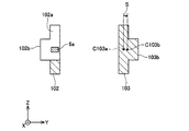
(第1変形例)図5は、第1変形例のバスバ102、103を有するバスバモジュール110の斜視図である。なお、前述したように、センサ基板、及び、バスバモジュール全体の図示は省略している。図5は、磁電変換素子6a、6bの付近のみを表しており、バスバ102、103は、それら一部だけが示されている。以降の図でも同様である。
(First Modification) FIG. 5 is a perspective view of a
バスバ102とバスバ103は、断面が扁平であり、幅広の側面が対向するように配置されている。バスバ102とバスバ103は、延設方向で異なる位置に切欠102a、103aが設けられている。夫々の切欠の内側に磁電変換素子6a、6bが配置されている。ここまでの構成は、図1のバスバモジュール10と同じである。
The
バスバ102は、幅広の側面に、延設方向に伸びる突条102bを有している。同様に、バスバ103も幅広の側面に、延設方向に伸びる突条103bを有している。前述したように、「延設方向」は、バスバの長手方向を意味し、図中のX軸方向に相当する。バスバ103の突条103bは、隣接するバスバ2から遠い側の側面に設けられている。
The
突条102b、103bの利点を説明する。図6に、図5のIV−IV線における断面図を示す。図6の断面は、バスバ102の磁電変換素子6aを通り、延設方向に直交する断面である。図6によく示されているように、バスバ102とバスバ103は幅広の側面を対向させており、バスバ103の突条103bは、バスバ2から遠い側の側面に設けられている。図6に図示されているようにバスバ3の断面中心C103bは、突条103bがない場合の断面中心C103aよりも距離Sだけ、隣接するバスバ2の電流に起因する磁束を検出する磁電変換素子6aから離れる。バスバ3の断面中心C103bは、電流密度の中心に相当する。即ち、バスバ103を流れる電流の中心が、突条103bを設けることによって磁電変換素子6aから離れる。従って、バスバ3を流れる電流に起因する磁束が磁電変換素子6aの計測磁束密度(計測電流)に与える影響が小さくなる。図5と図6に示したバスバの形状は、電流計測のSN比(電流に起因する磁束の検出SN比)をさらに高める。
The advantages of the
バスバ102に設けられている突条102bは、隣接するバスバ103から離れる方向の側面に設けられている。従って、バスバ103の突条103bと同様に、突条102bは、バスバ102が発生する磁界の磁電変換素子6b(隣接するバスバ103の電流(磁束)を検知する磁電変換素子6b)への影響を低減する。
The
(第2変形例)突条102b、103bの代わりに、突部であっても同じ効果が得られる。図7は、バスバ202、203の側面に突部202b、203bが設けられたバスバモジュール210の一部を示す。バスバ202には切欠202aが設けられており、その切欠202aに、バスバ202を流れる電流に起因して発生する磁束を検出する磁電変換素子6aが配置されている。磁電変換素子6aを通る断面において、隣接するバスバ203には、磁電変換素子6aから離れる方向の側面に突部203bが設けられている。バスバモジュール210では、磁電変換素子6aを通る断面の形状は図6と同じになる。従ってバスバモジュール210もバスバモジュール110と同じ効果が得られる。バスバ202に設けられた突部202bについても同様の効果が得られる。
(Second Modification) The same effect can be obtained even with a protrusion instead of the
(第3変形例)これまで説明したバスバモジュールでは、複数のバスバは幅広の側面を対向させていた。本明細書が開示する技術は、複数のバスバが、幅狭の断面を対向するように配置されていてもよい。図8に、第3変形例のバスバモジュール310の一部を示す。図8は、バスバモジュール310において隣接する2本のバスバ302、303の配置を示す斜視図である。バスバ302と303は、その幅狭の側面を対向させて平行に配置される。各バスバ302、303は幅広の側面に切欠302a、303aが設けられている。切欠302a、303aは、バスバの延設方向(図中のX軸方向)に沿って異なる位置に設けられている。各切欠の内部に、磁電変換素子6a、6bが配置されている。磁電変換素子6a、6bは、夫々の切欠の底面に対向するように配置されている。夫々の磁電変換素子6a、6bは、夫々のバスバに流れる電流に起因して発生する磁界(磁束密度)を検出する。磁界は流れる電流と一意の関係があるので、夫々の磁電変換素子6a、6bが検出する磁束密度により、夫々のバスバに流れる電流の大きさが特定できる。
(Third Modification) In the bus bar modules described so far, the plurality of bus bars face the wide side surfaces. In the technology disclosed in the present specification, a plurality of bus bars may be arranged so as to face narrow cross sections. FIG. 8 shows a part of the
図1−図4に示したバスバモジュール10と、図8のバスバモジュール310は、断面矩形のバスバの姿勢(延設方向からみたときのバスバの姿勢)が異なるだけである。本明細書が開示する技術はバスバモジュール10とバスバモジュール310を与えるが、バスバモジュール310よりはバスバモジュール10の方が電流計測のSN比が高い。その理由を説明する。
The
図9Aは、磁電変換素子6をバスバ402の幅狭の側面に対向するように配置したときの断面図を示しており、図9Bは、磁電変換素子6をバスバ403の幅広の側面に対向するように配置したときの断面図を示している。図9Aのケースでは、磁電変換素子6に対向する側面(幅狭の側面)の幅Waと、その側面に交差する側面(幅広の側面)の幅Haの比が、Wa/Ha=1/10である。図9Bのケースでは、磁電変換素子6に対向する側面(幅広の側面)の幅Wbと、その側面に交差する側面(幅狭の側面)の幅Hbの比が、Wb/Hb=10/1である。即ち、バスバ403は、その延設方向からみたときにバスバ402を90度回転させたものに相当する。図9Aのケースと図9Bのケースの夫々について、磁電変換素子6の中心位置(図9Aの場合はポイントP2、図9Bの場合はポイントP3)における磁束密度の強さをシミュレーションにより求めた。
FIG. 9A shows a cross-sectional view when the
シミュレーションの結果を図10に示す。図9Aのケースも図9Bのケースもバスバの断面積は同じである。また、図9Aのケースと図9Bのケースに同じ電流を与えてシミュレーションした。グループA(四角のプロット群)が図9Aのケースの結果であり、グループB(三角のプロット群)が図9Bのケースの結果を示す。なお、グループC(円のプロット群)は、同じ断面積であって、アスペクト比が1.0、即ち、断面が正方形のケースの結果を示している。いずれのグループも、バスバの断面中心から磁束検出ポイントまでの距離Lを変えてシミュレーションした結果である。距離Lは、図9Aのケースの場合は、バスバ断面中心C402から磁束検出ポイントP2までの距離であり、図9Bの場合は、バスバ断面中心C403から磁束検出ポイントP3までの距離である。基本的に、図9Aのケースの方が、図9Bのケースよりも距離Lが長い。図10のグラフに表れているように、グループA(バスバの幅狭の側面に対向するように磁電変換素子を配置するケース)の方が、グループB(バスバの幅広の側面に対向するように磁電変換素子を配置するケース)よりも、磁電変換素子を配置するポイントにおける磁束密度が高いことがわかる。この結果から、バスバの幅狭の側面から切欠を設け、その切欠に磁電変換素子を配置する方が、バスバの幅広の側面から切欠を設け、その切欠に磁電変換素子を配置するよりも電流計測のSN比を高くできることがわかる。 The result of the simulation is shown in FIG. The cross-sectional area of the bus bar is the same in both the case of FIG. 9A and the case of FIG. 9B. Further, the simulation was performed by applying the same current to the case of FIG. 9A and the case of FIG. 9B. Group A (square plot group) shows the result of the case of FIG. 9A, and group B (triangular plot group) shows the result of the case of FIG. 9B. Group C (circle plot group) shows the result of the case where the cross-sectional area is the same and the aspect ratio is 1.0, that is, the cross-section is square. All groups are the results of simulation by changing the distance L from the cross-sectional center of the bus bar to the magnetic flux detection point. In the case of FIG. 9A, the distance L is a distance from the bus bar cross-sectional center C402 to the magnetic flux detection point P2, and in FIG. 9B, it is a distance from the bus bar cross-sectional center C403 to the magnetic flux detection point P3. Basically, the distance L is longer in the case of FIG. 9A than in the case of FIG. 9B. As shown in the graph of FIG. 10, group A (a case where the magnetoelectric conversion element is disposed so as to face the narrow side surface of the bus bar) is more likely to face group B (the wide side surface of the bus bar). It can be seen that the magnetic flux density at the point where the magnetoelectric conversion element is arranged is higher than in the case where the magnetoelectric conversion element is arranged. From this result, it is better to measure the current by providing a notch from the narrow side of the bus bar and placing the magnetoelectric conversion element in the notch than by providing a notch from the wide side of the bus bar and placing the magnetoelectric conversion element in the notch. It can be seen that the SN ratio can be increased.
また、断面のアスペクト比が1.0に近いほどバスバの周囲に発生する磁束密度が高くなる(図10のグループCの結果を参照)。扁平な断面の幅狭の側面に切欠を設けると、バスバの残部の断面形状のアスペクト比は1.0に近くなっていく。この点も、電流計測のSN比を高めることに寄与する。 Further, as the aspect ratio of the cross section is closer to 1.0, the magnetic flux density generated around the bus bar becomes higher (see the result of group C in FIG. 10). When a notch is provided on a narrow side surface of a flat cross section, the aspect ratio of the cross-sectional shape of the remaining portion of the bus bar approaches 1.0. This point also contributes to increasing the SN ratio of current measurement.
さらにまた、バスバの幅広の側面を対向させるとともに、切欠を幅狭の側面に設けることは、次の効果も奏する。図4によく示されているように、バスバ2を流れる電流に起因する磁束を検出する磁電変換素子6aは、電流計測対象(磁束検出対象)のバスバ2に隣接するバスバ3の幅広の側面と対向する位置関係となる。前述したように、幅広の側面に対向するように磁電変換素子を配置すると(図10のグループB)、幅狭の側面に対向するように磁電変換素子を配置する場合(図10のグループA)と比較して磁電変換素子が検出する磁束密度が小さくなる。そして、磁電変換素子6aの位置ではバスバ3を流れる電流に起因する磁界は、磁電変換素子6aの感磁面7と平行である。一方、隣接するバスバ3の電流に起因する磁束(バスバ3を流れる電流が発生する磁束)は、電流計測対象(磁束検出対象)のバスバ2を一巡するが、幅広の側面と対向する範囲では磁束が幅広の側面とほぼ平行となる。そうすると、バスバ3が発生する磁束は磁電変換素子6aの感磁面7を貫かない。そして、バスバ3が発生する磁界はバスバ3の幅広の側面と平行なので、磁電変換素子6aの位置がバスバ2の幅広の側面の幅方向(図4のプラスマイナスZ方向)にずれても、バスバ3が発生する磁界は磁電変換素子6aの感磁面に平行なままとなる。即ち、バスバ3の幅広の側面と平行に磁電変換素子の位置が多少ずれても、バスバ3から磁電変換素子6aが受ける影響は変化し難い(位置ずれに対して外乱の影響を受け難い)。以上の点は全て、電流計測対象のバスバ2に隣接するバスバ3から磁電変換素子6aが受ける影響を抑制することに寄与する。
Furthermore, when the wide side surfaces of the bus bar are opposed to each other and the notch is provided on the narrow side surface, the following effects can be obtained. As shown well in FIG. 4, the
そのほか、断面が扁平のバスバの幅狭の側面に切欠を設けることには、幅広の側面に切欠を設ける場合と比較して、切欠の深さを深くできる。このことは、磁電変換素子の配置位置の自由度を高める。 In addition, the depth of the notch can be increased by providing the notch on the narrow side surface of the bus bar having a flat cross section as compared with the case where the notch is provided on the wide side surface. This increases the degree of freedom of the arrangement position of the magnetoelectric transducer.
(第4変形例)次に、図11を参照して、第4変形例のバスバモジュール510を説明する。この第4変形例は、2本のバスバを有するバスバモジュール510である。2本のバスバ(第1バスバ502と第2バスバ503)は、平行に配置されている。第1バスバ502は、バスバ延設方向の一方(図中のX軸の正方向)に向かって太い部位502fから細い部位502eに変化する段差502dを有している。また、第2バスバ503は、バスバ延設方向の一方(図中のX軸の正方向)に向かって細い部位503eから太い部位503fに変化する段差503dを有している。
(Fourth Modification) Next, a
第1バスバ502を流れる電流に起因する磁束を検出する磁電変換素子6aは、第1バスバ502の細い部位502eに対向するように配置されている。第2バスバ503を流れる電流に起因する磁束(電流)を検出する磁電変換素子6bは、第2バスバ503の細い部位503eに対向するように配置されている。第1バスバ502の細い部位502eは、第2バスバ503の太い部位503fと隣接する。第2バスバ503の細い部位503eは、第1バスバ502の太い部位502fと隣接する。即ち、磁電変換素子6aを通る断面における第1バスバ502の断面積(細い部位502eの断面積)は、第2バスバ503の断面積(太い部位503fの断面積)よりも小さい。また、磁電変換素子6bを通る断面における第2バスバ503の断面積(細い部位503eの断面積)は、第1バスバ502の断面積(太い部位502fの断面積)よりも小さい。このバスバモジュール510も、先のバスバモジュールと同様に電流計測のSN比(磁束検出のSN比)が従来の電流計測装置よりも高い。
The
第4変形例のバスバモジュール510の特徴的構造は、次のように表現できる。バスバモジュール510の第1バスバ502は、その延設方向の一方向に向かって太い部位502fから細い部位502eに変化する段差502dを有している。第2バスバ503は、上記一方向に向かって細い部位503eから太い部位503fに変化する段差503dを有している。第1磁電変換素子6aは、第1バスバ502の細い部位502eに対向している。そして、第2バスバ503の第1断面は、太い部位503fの断面である。
The characteristic structure of the
(第5変形例)図12と図13を参照して第5変形例のバスバモジュール610を説明する。図12は、バスバモジュール610の斜視図であり、図13は、センサ基板605を外した状態のバスバモジュール610の斜視図である。これまでの変形例の図と同様に、図12と図13でも、バスバモジュール全体の図示は省略し、3本のバスバの磁電変換素子を配置する部位だけが描かれている。
(Fifth Modification) A
バスバモジュール610では、複数のバスバ602、603、604は、幅狭の側面が互いに対向するように配置される。そして、各バスバには、その幅広の側面が窪むように屈曲部602a、603a、604aが設けられている。屈曲部は、X軸の正方向に伸びるバスバの一部が、Z軸の負方向に折れ曲がり、次いでX軸の正方向に折れ曲がり、さらにZ軸の正方向に折れ曲がり、最後に再びX軸の正方向に折れ曲がる。そのような屈曲により、バスバの幅広の側面に窪みが形成される。センサ基板605は、各バスバの窪み(屈曲部)に嵌合するとともに、隣接するバスバの一対の対向面に挟まれる。また、各バスバの屈曲部の内側に磁電変換素子6a−6cが位置するように、センサ基板605に磁電変換素子が固定される。
In the
第5変形例のバスバモジュールでは、バスバの幅広の側面が面外方向に折れ曲がるようにして屈曲部が形成されている。従って各バスバには幅広の側面の幅の窪みが形成され、その窪みにセンサ基板605が嵌合している、図12、図13によく示されているように、各バスバとセンサ基板は、X軸方向とY軸方向のいずれでも長い距離で接している。従って複数のバスバは相対的に動き難く、相対位置関係がしっかりと保持される。
In the bus bar module of the fifth modified example, the bent portion is formed so that the wide side surface of the bus bar is bent in the out-of-plane direction. Accordingly, each bus bar is formed with a wide-side depression, and the
実施例で説明した技術に関する留意点を述べる。実施例のバスバモジュールは、総じて言えば、平行に配置されている第1バスバ及び第2バスバと、第1バスバの側面に対向するように配置されている第1磁電変換素子と、第2バスバの側面に対向するように配置されている第2磁電変換素子を備えており、第1磁電変換素子を通り第1及び第2バスバの延設方向と直交する断面における第1バスバの断面積が第2バスバの断面積よりも小さい。また、第2磁電変換素子を通り第1及び第2バスバの延設方向と直交する断面における第2バスバの断面積が第1バスバの断面積よりも小さい。実施例の技術は、総じて言えば、磁界を検出するポイントにおいて、平行なバスバの断面積を相対的に異ならしめることで、電流計測のSN比を高める。 Points to be noted regarding the technology described in the embodiments will be described. Generally speaking, the bus bar module of the embodiment includes a first bus bar and a second bus bar that are arranged in parallel, a first magnetoelectric conversion element that is arranged to face the side surface of the first bus bar, and a second bus bar. The first bus bar has a cross-sectional area in a cross section that passes through the first magnetoelectric conversion element and is orthogonal to the extending direction of the first and second bus bars. It is smaller than the cross-sectional area of the second bus bar. Further, the cross-sectional area of the second bus bar in a cross section that passes through the second magnetoelectric conversion element and is orthogonal to the extending direction of the first and second bus bars is smaller than the cross-sectional area of the first bus bar. Generally speaking, the technique of the embodiment increases the SN ratio of current measurement by making the cross-sectional areas of parallel bus bars relatively different at the point where the magnetic field is detected.
実施例はインバータの出力の伝送に用いるバスバモジュールであった。本明細書が開示するバスバモジュールは、インバータ以外にも適用することができる。 The embodiment is a bus bar module used for transmission of the output of the inverter. The bus bar module disclosed in this specification can be applied to other than the inverter.
図1−図4のバスバモジュールにおけるバスバ2が第1バスバの一例に相当し、バスバ3が第2バスバの一例に相当する。また、バスバ2の切欠2aに配置されている磁電変換素子6aが第1磁電変換素子の一例に相当し、バスバ3の切欠3aに配置されている磁電変換素子6bが第2磁電変換素子の一例に相当する。
The
本明細書が開示する技術は2本以上のバスバを有するバスバモジュールに適用することができ、バスバの数に制限はない。例えば、2個の3相モータに電力を供給するインバータは、合計で6本のバスバを備える。本明細書が開示する技術は、6本、あるいはそれ以上のバスバを有するバスバモジュールに適用することもできる。 The technology disclosed in this specification can be applied to a bus bar module having two or more bus bars, and the number of bus bars is not limited. For example, an inverter that supplies power to two three-phase motors includes a total of six bus bars. The technology disclosed in this specification can also be applied to a bus bar module having six or more bus bars.
本明細書における電動車両には、電気自動車、ハイブリッド車、燃料電池車が含まれる。 The electric vehicle in this specification includes an electric vehicle, a hybrid vehicle, and a fuel cell vehicle.
以上、本発明の具体例を詳細に説明したが、これらは例示に過ぎず、特許請求の範囲を限定するものではない。特許請求の範囲に記載の技術には、以上に例示した具体例を様々に変形、変更したものが含まれる。本明細書または図面に説明した技術要素は、単独であるいは各種の組合せによって技術的有用性を発揮するものであり、出願時請求項記載の組合せに限定されるものではない。また、本明細書または図面に例示した技術は複数目的を同時に達成し得るものであり、そのうちの一つの目的を達成すること自体で技術的有用性を持つものである。 Specific examples of the present invention have been described in detail above, but these are merely examples and do not limit the scope of the claims. The technology described in the claims includes various modifications and changes of the specific examples illustrated above. The technical elements described in this specification or the drawings exhibit technical usefulness alone or in various combinations, and are not limited to the combinations described in the claims at the time of filing. In addition, the technology exemplified in this specification or the drawings can achieve a plurality of objects at the same time, and has technical usefulness by achieving one of the objects.
2、3、4:バスバ
2a、3a、4a:切欠
5:センサ基板
6a、6b、6c:磁電変換素子
7:感磁面
9:ホルダ
10:バスバモジュール
50:積層ユニット
51a、51b、51c:パワーカード
52:冷却器
102b、103b:突条
2, 3, 4: Bus bars 2a, 3a, 4a: Notch 5:
Claims (6)
第1切欠が設けられている第1バスバと、
第1バスバと平行に配置されており、第1バスバの延設方向で前記第1切欠と異なる位置に第2切欠が設けられている第2バスバと、
前記第1切欠と前記第2切欠の双方に嵌合しているとともに、前記第1バスバと前記第2バスバの対向する側面に挟まれている基板と、
前記第1切欠の内側に位置するように基板に固定されている第1磁電変換素子と、
を備えていることを特徴とするバスバモジュール。 A bus bar module with a current sensor,
A first bus bar provided with a first notch;
A second bus bar that is arranged in parallel with the first bus bar and has a second notch at a position different from the first notch in the extending direction of the first bus bar;
A board that is fitted in both the first notch and the second notch, and is sandwiched between opposing sides of the first bus bar and the second bus bar,
A first magnetoelectric conversion element fixed to the substrate so as to be located inside the first notch;
A bus bar module comprising:
前記第1切欠は、前記第1バスバの幅狭の側面に設けられており、
前記第2切欠は、前記第1切欠と同じ側の前記第2バスバの幅狭の側面に設けられている、
ことを特徴とする請求項1又は2に記載のバスバモジュール。 The first and second bus bars have a wide side surface and a narrow side surface, and are arranged in parallel so that the wide side surface faces each other,
The first notch is provided on a narrow side surface of the first bus bar,
The second notch is provided on a narrow side surface of the second bus bar on the same side as the first notch,
The bus bar module according to claim 1 or 2.
クランク状の第1屈曲部が設けられている第1バスバと、
第1バスバと平行に配置されており、第1バスバの延設方向で前記第1屈曲部と異なる位置にクランク状の第2屈曲部が設けられている第2バスバと、
前記第1屈曲部と前記第2屈曲部の双方に嵌合しているとともに、前記第1バスバと前記第2バスバの対向する側面に挟まれている基板と、
前記第1屈曲部の内側に位置するように基板に固定されている第1磁電変換素子と、
前記第2屈曲部の内側に位置するように基板に固定されている第2磁電変換素子と、
を備えていることを特徴とするバスバモジュール。 A bus bar module with a current sensor,
A first bus bar provided with a crank-shaped first bent portion;
A second bus bar that is arranged in parallel with the first bus bar, and has a crank-shaped second bent portion at a position different from the first bent portion in the extending direction of the first bus bar;
A substrate that is fitted to both the first bent portion and the second bent portion, and is sandwiched between opposing sides of the first bus bar and the second bus bar,
A first magnetoelectric conversion element fixed to the substrate so as to be located inside the first bent portion;
A second magnetoelectric conversion element fixed to the substrate so as to be located inside the second bent portion;
A bus bar module comprising:
Priority Applications (6)
| Application Number | Priority Date | Filing Date | Title |
|---|---|---|---|
| JP2013253353A JP5945976B2 (en) | 2013-12-06 | 2013-12-06 | Bus bar module |
| CA2932566A CA2932566C (en) | 2013-12-06 | 2014-12-03 | Bus bar module |
| PCT/IB2014/002642 WO2015082980A1 (en) | 2013-12-06 | 2014-12-03 | Bus bar module |
| CN201480066239.7A CN105934677B (en) | 2013-12-06 | 2014-12-03 | Busbar module |
| EP14816388.4A EP3077832B1 (en) | 2013-12-06 | 2014-12-03 | Bus bar module |
| US15/100,127 US10393774B2 (en) | 2013-12-06 | 2014-12-03 | Bus bar module |
Applications Claiming Priority (1)
| Application Number | Priority Date | Filing Date | Title |
|---|---|---|---|
| JP2013253353A JP5945976B2 (en) | 2013-12-06 | 2013-12-06 | Bus bar module |
Publications (2)
| Publication Number | Publication Date |
|---|---|
| JP2015111080A JP2015111080A (en) | 2015-06-18 |
| JP5945976B2 true JP5945976B2 (en) | 2016-07-05 |
Family
ID=52144761
Family Applications (1)
| Application Number | Title | Priority Date | Filing Date |
|---|---|---|---|
| JP2013253353A Active JP5945976B2 (en) | 2013-12-06 | 2013-12-06 | Bus bar module |
Country Status (6)
| Country | Link |
|---|---|
| US (1) | US10393774B2 (en) |
| EP (1) | EP3077832B1 (en) |
| JP (1) | JP5945976B2 (en) |
| CN (1) | CN105934677B (en) |
| CA (1) | CA2932566C (en) |
| WO (1) | WO2015082980A1 (en) |
Families Citing this family (12)
| Publication number | Priority date | Publication date | Assignee | Title |
|---|---|---|---|---|
| JP6064918B2 (en) * | 2014-01-10 | 2017-01-25 | トヨタ自動車株式会社 | Current sensor |
| WO2017014040A1 (en) * | 2015-07-22 | 2017-01-26 | 株式会社村田製作所 | Current sensor |
| JP6137280B2 (en) * | 2015-11-20 | 2017-05-31 | 株式会社安川電機 | Power converter |
| WO2018012034A1 (en) * | 2016-07-15 | 2018-01-18 | アルプス電気株式会社 | Current sensor |
| WO2018051575A1 (en) * | 2016-09-14 | 2018-03-22 | 旭化成エレクトロニクス株式会社 | Electric current sensor |
| KR102614123B1 (en) * | 2016-11-24 | 2023-12-13 | 현대자동차주식회사 | Inverter structure for vehicle |
| WO2018163685A1 (en) * | 2017-03-06 | 2018-09-13 | アルプス電気株式会社 | Current sensor |
| WO2018163684A1 (en) * | 2017-03-06 | 2018-09-13 | アルプス電気株式会社 | Current sensor |
| US10717401B2 (en) | 2017-04-21 | 2020-07-21 | Ford Global Technologies, Llc | Terminal block assembly for electrified vehicles |
| JP6883241B2 (en) * | 2017-05-22 | 2021-06-09 | 株式会社アイシン | Current sensor |
| CN112114180A (en) * | 2019-06-20 | 2020-12-22 | 株式会社电装 | Sensor unit |
| CN113030546A (en) | 2019-12-25 | 2021-06-25 | 阿尔卑斯阿尔派株式会社 | Current sensor |
Family Cites Families (14)
| Publication number | Priority date | Publication date | Assignee | Title |
|---|---|---|---|---|
| JP3696448B2 (en) | 1999-09-02 | 2005-09-21 | 矢崎総業株式会社 | Current detector |
| JP2001272422A (en) * | 2000-03-27 | 2001-10-05 | Jeco Co Ltd | Current detector for vehicle |
| JP4552513B2 (en) * | 2004-05-26 | 2010-09-29 | トヨタ自動車株式会社 | Power control unit and unit case thereof |
| JP4385892B2 (en) * | 2004-08-19 | 2009-12-16 | トヨタ自動車株式会社 | Current detector |
| JP2007147565A (en) * | 2005-11-30 | 2007-06-14 | Toyota Motor Corp | Structure of current detector, and core fixing jig |
| US7768083B2 (en) * | 2006-01-20 | 2010-08-03 | Allegro Microsystems, Inc. | Arrangements for an integrated sensor |
| JP4833111B2 (en) * | 2006-09-20 | 2011-12-07 | 株式会社東海理化電機製作所 | Current detector |
| JP4905254B2 (en) * | 2007-05-25 | 2012-03-28 | トヨタ自動車株式会社 | Manufacturing method of bus bar with integrated capacitor |
| JP5418811B2 (en) * | 2009-01-30 | 2014-02-19 | アイシン・エィ・ダブリュ株式会社 | Current detector |
| JP4839393B2 (en) * | 2009-05-13 | 2011-12-21 | 本田技研工業株式会社 | Current detector |
| JP2011080970A (en) * | 2009-10-02 | 2011-04-21 | Kohshin Electric Corp | Detection device of multiphase current |
| JP5614143B2 (en) * | 2010-07-21 | 2014-10-29 | セイコーエプソン株式会社 | Information processing system, printing apparatus, and information processing method |
| WO2013005458A1 (en) * | 2011-07-04 | 2013-01-10 | アルプス・グリーンデバイス株式会社 | Current sensor |
| JP5945975B2 (en) | 2013-12-06 | 2016-07-05 | トヨタ自動車株式会社 | Bus bar module |
-
2013
- 2013-12-06 JP JP2013253353A patent/JP5945976B2/en active Active
-
2014
- 2014-12-03 WO PCT/IB2014/002642 patent/WO2015082980A1/en active Application Filing
- 2014-12-03 US US15/100,127 patent/US10393774B2/en active Active
- 2014-12-03 CA CA2932566A patent/CA2932566C/en active Active
- 2014-12-03 CN CN201480066239.7A patent/CN105934677B/en active Active
- 2014-12-03 EP EP14816388.4A patent/EP3077832B1/en active Active
Also Published As
| Publication number | Publication date |
|---|---|
| US10393774B2 (en) | 2019-08-27 |
| CA2932566A1 (en) | 2015-06-11 |
| CN105934677A (en) | 2016-09-07 |
| EP3077832B1 (en) | 2019-10-16 |
| US20170003323A1 (en) | 2017-01-05 |
| EP3077832A1 (en) | 2016-10-12 |
| CA2932566C (en) | 2018-05-01 |
| JP2015111080A (en) | 2015-06-18 |
| WO2015082980A1 (en) | 2015-06-11 |
| CN105934677B (en) | 2019-09-27 |
Similar Documents
| Publication | Publication Date | Title |
|---|---|---|
| JP5945976B2 (en) | Bus bar module | |
| US8427133B2 (en) | Current detection apparatus | |
| JP6122128B2 (en) | Current sensor | |
| CN102713645B (en) | Current detection device | |
| JP5489145B1 (en) | Current sensor | |
| JP5224838B2 (en) | Electromagnetic induction encoder | |
| CN109313223B (en) | Current sensor | |
| JP5945975B2 (en) | Bus bar module | |
| JP5699993B2 (en) | Inverter | |
| CN104007305A (en) | Current sensor | |
| WO2017217267A1 (en) | Electric current sensor | |
| JP6536544B2 (en) | Current sensor | |
| JP2019138815A (en) | Current sensor | |
| JP2005321206A (en) | Current detection device | |
| JP2016099111A (en) | Current sensor | |
| JP6536553B2 (en) | Current sensor | |
| JP6237525B2 (en) | Current sensor | |
| JP3191252U (en) | Current sensor | |
| JP2016200549A (en) | Current-voltage sensor | |
| JP2015184175A (en) | current sensor and current sensor set | |
| JP5622027B2 (en) | Multiphase current detector | |
| JP2020056754A (en) | Electromagnetic induction encoder | |
| JP6134964B2 (en) | Inductive displacement detector | |
| JP6802098B2 (en) | Current sensor | |
| JPWO2018008180A1 (en) | Current sensor |
Legal Events
| Date | Code | Title | Description |
|---|---|---|---|
| A977 | Report on retrieval |
Free format text: JAPANESE INTERMEDIATE CODE: A971007 Effective date: 20150903 |
|
| A131 | Notification of reasons for refusal |
Free format text: JAPANESE INTERMEDIATE CODE: A131 Effective date: 20150915 |
|
| A521 | Request for written amendment filed |
Free format text: JAPANESE INTERMEDIATE CODE: A523 Effective date: 20151112 |
|
| TRDD | Decision of grant or rejection written | ||
| A01 | Written decision to grant a patent or to grant a registration (utility model) |
Free format text: JAPANESE INTERMEDIATE CODE: A01 Effective date: 20160506 |
|
| A61 | First payment of annual fees (during grant procedure) |
Free format text: JAPANESE INTERMEDIATE CODE: A61 Effective date: 20160519 |
|
| R151 | Written notification of patent or utility model registration |
Ref document number: 5945976 Country of ref document: JP Free format text: JAPANESE INTERMEDIATE CODE: R151 |
|
| S111 | Request for change of ownership or part of ownership |
Free format text: JAPANESE INTERMEDIATE CODE: R313113 |
|
| R350 | Written notification of registration of transfer |
Free format text: JAPANESE INTERMEDIATE CODE: R350 |
|
| R250 | Receipt of annual fees |
Free format text: JAPANESE INTERMEDIATE CODE: R250 |
|
| R250 | Receipt of annual fees |
Free format text: JAPANESE INTERMEDIATE CODE: R250 |
|
| R250 | Receipt of annual fees |
Free format text: JAPANESE INTERMEDIATE CODE: R250 |
|
| R250 | Receipt of annual fees |
Free format text: JAPANESE INTERMEDIATE CODE: R250 |