EP3327239A1 - Verfahren zum herstellen eines türblattes sowie türblatt - Google Patents
Verfahren zum herstellen eines türblattes sowie türblatt Download PDFInfo
- Publication number
- EP3327239A1 EP3327239A1 EP17203665.9A EP17203665A EP3327239A1 EP 3327239 A1 EP3327239 A1 EP 3327239A1 EP 17203665 A EP17203665 A EP 17203665A EP 3327239 A1 EP3327239 A1 EP 3327239A1
- Authority
- EP
- European Patent Office
- Prior art keywords
- mat
- contour
- filling material
- door leaf
- shaped filling
- Prior art date
- Legal status (The legal status is an assumption and is not a legal conclusion. Google has not performed a legal analysis and makes no representation as to the accuracy of the status listed.)
- Granted
Links
Images

Classifications
-
- E—FIXED CONSTRUCTIONS
- E06—DOORS, WINDOWS, SHUTTERS, OR ROLLER BLINDS IN GENERAL; LADDERS
- E06B—FIXED OR MOVABLE CLOSURES FOR OPENINGS IN BUILDINGS, VEHICLES, FENCES OR LIKE ENCLOSURES IN GENERAL, e.g. DOORS, WINDOWS, BLINDS, GATES
- E06B3/00—Window sashes, door leaves, or like elements for closing wall or like openings; Layout of fixed or moving closures, e.g. windows in wall or like openings; Features of rigidly-mounted outer frames relating to the mounting of wing frames
- E06B3/70—Door leaves
- E06B3/7001—Coverings therefor; Door leaves imitating traditional raised panel doors, e.g. engraved or embossed surfaces, with trim strips applied to the surfaces
-
- E—FIXED CONSTRUCTIONS
- E06—DOORS, WINDOWS, SHUTTERS, OR ROLLER BLINDS IN GENERAL; LADDERS
- E06B—FIXED OR MOVABLE CLOSURES FOR OPENINGS IN BUILDINGS, VEHICLES, FENCES OR LIKE ENCLOSURES IN GENERAL, e.g. DOORS, WINDOWS, BLINDS, GATES
- E06B3/00—Window sashes, door leaves, or like elements for closing wall or like openings; Layout of fixed or moving closures, e.g. windows in wall or like openings; Features of rigidly-mounted outer frames relating to the mounting of wing frames
- E06B3/70—Door leaves
- E06B3/7015—Door leaves characterised by the filling between two external panels
- E06B2003/7032—Door leaves characterised by the filling between two external panels of non-vegetal fibrous material, e.g. glass or rock wool
-
- E—FIXED CONSTRUCTIONS
- E06—DOORS, WINDOWS, SHUTTERS, OR ROLLER BLINDS IN GENERAL; LADDERS
- E06B—FIXED OR MOVABLE CLOSURES FOR OPENINGS IN BUILDINGS, VEHICLES, FENCES OR LIKE ENCLOSURES IN GENERAL, e.g. DOORS, WINDOWS, BLINDS, GATES
- E06B3/00—Window sashes, door leaves, or like elements for closing wall or like openings; Layout of fixed or moving closures, e.g. windows in wall or like openings; Features of rigidly-mounted outer frames relating to the mounting of wing frames
- E06B3/70—Door leaves
- E06B3/7015—Door leaves characterised by the filling between two external panels
-
- E—FIXED CONSTRUCTIONS
- E06—DOORS, WINDOWS, SHUTTERS, OR ROLLER BLINDS IN GENERAL; LADDERS
- E06B—FIXED OR MOVABLE CLOSURES FOR OPENINGS IN BUILDINGS, VEHICLES, FENCES OR LIKE ENCLOSURES IN GENERAL, e.g. DOORS, WINDOWS, BLINDS, GATES
- E06B3/00—Window sashes, door leaves, or like elements for closing wall or like openings; Layout of fixed or moving closures, e.g. windows in wall or like openings; Features of rigidly-mounted outer frames relating to the mounting of wing frames
- E06B3/70—Door leaves
- E06B3/72—Door leaves consisting of frame and panels, e.g. of raised panel type
- E06B3/76—Door leaves consisting of frame and panels, e.g. of raised panel type with metal panels
-
- E—FIXED CONSTRUCTIONS
- E06—DOORS, WINDOWS, SHUTTERS, OR ROLLER BLINDS IN GENERAL; LADDERS
- E06B—FIXED OR MOVABLE CLOSURES FOR OPENINGS IN BUILDINGS, VEHICLES, FENCES OR LIKE ENCLOSURES IN GENERAL, e.g. DOORS, WINDOWS, BLINDS, GATES
- E06B3/00—Window sashes, door leaves, or like elements for closing wall or like openings; Layout of fixed or moving closures, e.g. windows in wall or like openings; Features of rigidly-mounted outer frames relating to the mounting of wing frames
- E06B3/70—Door leaves
- E06B3/72—Door leaves consisting of frame and panels, e.g. of raised panel type
- E06B3/78—Door leaves consisting of frame and panels, e.g. of raised panel type with panels of plastics
-
- E—FIXED CONSTRUCTIONS
- E06—DOORS, WINDOWS, SHUTTERS, OR ROLLER BLINDS IN GENERAL; LADDERS
- E06B—FIXED OR MOVABLE CLOSURES FOR OPENINGS IN BUILDINGS, VEHICLES, FENCES OR LIKE ENCLOSURES IN GENERAL, e.g. DOORS, WINDOWS, BLINDS, GATES
- E06B5/00—Doors, windows, or like closures for special purposes; Border constructions therefor
- E06B5/10—Doors, windows, or like closures for special purposes; Border constructions therefor for protection against air-raid or other war-like action; for other protective purposes
- E06B5/16—Fireproof doors or similar closures; Adaptations of fixed constructions therefor
Definitions
- the invention relates to a method for producing a door leaf, in particular a door leaf for a trained as a fire and / or as the outer end of a building door, and a door leaf, which is made in particular with such a method.
- Door leaves can be made by various methods.
- door panels for example in the so-called box-lid construction, in which a door leaf filling is placed loosely in a box, and then a lid is firmly connected to this box. The cohesion of the individual parts of the door leaf is then via a connection of Kastel with cover, for example along the edge regions.
- Such door leaves are for example off EP 2 612 979 A2 known.
- a door leaf has to fulfill special functions, such as a front door or a fire door, it is important that the individual materials fulfill predefined properties.
- a door should, for example, have the lowest possible fire load. Additionally, it is important to have as few joints within the door leaf are present to prevent the passage of fumes through these joints.
- the object of the invention is to propose a method for producing a door leaf and such a door leaf, which is inexpensive to mass-produce and also special functions, such as a fire protection function can meet.
- a door leaf, which is produced in particular by such a method is the subject of the independent claim.
- a filling material in mat form is not simply introduced in the form of an unstructured mat in an interior of the door leaf, but it is carried out a separate prefabrication step, in which the filling material a predefined mat shape contour is impressed.
- This mat shape contour substantially corresponds to the broad side shape contour, which has also been introduced into the forming plate in a prefabrication step, and is also arranged in the same position in the assembled state of the door leaf.
- a sheet steel is used as a flat forming plate, wherein the predefined broad side contour shape is embossed by a standard embossing process.
- Steel sheets are particularly inexpensive and therefore particularly advantageous from the cost aspect for forming the forming plate, which defines the outer broad side of the door leaf.
- the forming plate can also be a composite plate, in particular a composite plate made of glass fiber reinforced plastic, wherein the predefined broad side contour shape is impressed by a hot pressing process.
- a mineral wool mat in particular a web-reinforced mineral wool mat
- a mineral wool mat is used as the mat-shaped filling material.
- Mineral wool mats are particularly advantageous when the door leaf is to be used for a fire, because mineral wool represents a low fire load of the door leaf due to the non-combustibility.
- Such web-reinforced mineral wool mats can be purchased, for example, from Rockwool.
- the predefined mat shape contour of the mat-shaped filling material is introduced in an advantageous embodiment by an embossing method or by a milling process in the mat-shaped filling material.
- an embossing method or by a milling process in the mat-shaped filling material.
- the embossing process For this purpose, easily exchangeable negative molds can be used on a standard stamp, which, depending on the form, which is to be embossed in the mat-shaped filling material, are used.
- a cassette contour is stamped in each case as a broad-side contour contour and as a mat-shaped contour, the stamping taking place, in particular, as sunk relief.
- the recessed relief of the mat contour has a depth which is greater by 20% to 25% than a depth of the recessed relief of the broad side contour.
- the mat-shaped filling material usually has a certain springback behavior, which is advantageously taken into account when introducing the predefined mat shape contour. Therefore, the insertion of the recessed relief of the mat molding contour is made with a greater depth than that of the broad side mold contour. In experiments, it has been found that a difference of 20% to 25% in the depth is sufficient, so that after joining the forming plate and the mat-shaped filling material, a direct close contact of the two materials is possible.
- the joining of the forming plate and the mat-shaped filling material takes place in such a way that the broad-side shape contour and the mat shape contour come into flush contact with each other.
- This is particularly advantageous in the use of the door leaf as a fire, since this can be advantageously avoided the occurrence of larger joints within the door leaf.
- a box is formed from a first Umformplatine, wherein from a second Umformplatine a lid is formed, wherein upon assembly of the Umformplatinen and the mat-shaped filling material, the mat-shaped filler inserted into the box and then the box is closed with the lid. It is particularly advantageous if both Umformplatinen and both sides of the mat-shaped filling material each have a shape contour that can interlock.
- the forming plate and the mat-shaped filling material are joined together to form a sandwich plate, wherein the forming plate and the mat-shaped filling material are glued together in particular.
- An advantageous door leaf is in particular produced by a method described above.
- the door leaf has at least one outer board for forming an outer broad side of the door leaf, wherein the outer board has a Breittimeformkontur in a predetermined surface area.
- the door leaf a mat-shaped filler material having a mat shape contour in a predetermined surface area.
- the outer board and the mat-shaped filling material are joined to form the door leaf.
- the broad-side shape contour and the mat shape contour are formed complementary to one another, so that the broad-side shape contour engages in the mat shape contour.
- the broad-side shape contour and the mat shape contour are each formed as recessed relief.
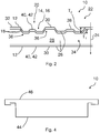
- Fig. 1 shows a front view of a door leaf 10, which can be used for example for a trained as the outer end of a building door, but also for a fire.
- the door leaf 10 has on an outer broad side 12 on a special broad side contour 14, which is formed in the present embodiment as a cassette contour 16 and in particular as recessed relief 18, ie, deformed to an inner region of the door leaf 10.
- the cassette contour 16 has four cassettes, it However, it is also possible that in an alternative motif design more or less cassettes are formed on the door panel 10.
- the cassette contour 16 is located at a predetermined surface area 20 of the door leaf 10th
- Fig. 2 shows a first embodiment of the door leaf 10 in a cross-sectional view along the line AA in FIG Fig. 1 , where in Fig. 2 the door leaf 10 is constructed as a sandwich plate 22.
- Sandwich panels 22 are characterized in that they have a plurality of layers 26 along a depth direction 24 of a door leaf 10, wherein the layers 26 are materially bonded and thus immovably connected to each other.
- a filling material 28 is provided as a first layer 26, wherein outer plates 30 of the door leaf 10 form a motif plate 32 and are adhesively bonded, e.g. by gluing, are connected directly to the filling material 28.
- such a sandwich panel 22 is shown in which a mat-shaped filling material 28, for example in the form of a mineral wool mat 34, is arranged between two outer panels 30, which form the outer broad sides 12 of the door leaf 10.
- a mat-shaped filling material 28 for example in the form of a mineral wool mat 34
- a first outer board 30 is formed as a flat outer board 30 without any motives therein.
- a second outer board 30 has at a predetermined surface area 20 a Breittimeformkontur 14, namely in Fig. 1 shown cassette contour 16. In Fig. 2 it can be seen that this is designed as sunk relief 18.
- the mat-shaped filling material 28 also has a corresponding mat shape contour 36, which is formed to be complementary to the wide-side shape contour 14 in the outer plate 30, so that the broad-side contour contour 14 can engage in the mat shape contour 36.
- the mat molding contour 36 and the wide-side mold contour 14 are thereby introduced into the mineral wool mat 34 and the outer board 30 prior to joining the individual layers 26, as described below with reference to FIG Fig. 3 is described.
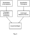
- Fig. 3 shows a schematic flow diagram of a method for producing a door leaf 10th
- first at least one forming plate 38 for forming a later outer plate 30 of the door leaf 10, and a mat-shaped filling material 28 are provided.
- the forming plate 38 can be provided, for example, as a flat sheet steel 40.
- a composite plate 42 as a forming plate 38, which comprises a glass fiber reinforced plastic.
- a mineral wool mat 34 is provided, wherein in particular a web-reinforced mineral wool mat 34 is used, which has an inherent stability, so that can be dispensed with further reinforcements within the door panel 10.
- the Breittimeformkontur 14 for example, the cassette contour 16, accordingly Fig. 1 imprinted.
- a plain steel sheet 40 by a standard embossing method.
- a composite plate 42 it is done by a hot press method.
- the mat-shaped filling material 28 is now also preprocessed, namely by impressing the mineral wool mat 34 likewise the cassette contour 16 as a mat shape contour 36.
- the impressing of the mold contours 14, 36 takes place here in each case as sunk relief 18, wherein the mat shape contour 36 has a greater depth T 1 when embossing, as a depth T 2 of the Breitreteformkontur 14 on the Umformplatine 38.
- the depth T 1 in the mineral wool mat 34 is 20% to 25% greater than the depth T 2 in the forming plate 38th
- the mold contours 14, 36 are then embossed into the mineral wool mat 34 or the forming plate 38, at the end of the process the forming plate 38 and the mat-shaped filling material 28, i. the mineral wool mat 34, joined together, in such a way that the Breittimeformkontur 14 engages in the mat shape contour 36.
- the joining can be done accordingly Fig. 2 done in a sandwich panel 22, for example by gluing. It can be used, for example, a PU adhesive.
- the door leaf 10 has a broad side contour 14 only on an outer broad side 12, but it is also conceivable to likewise provide such a broad side molding contour 14 on the opposite outer broad side 12.
- a sandwich panel 22 it is also possible to carry out the door leaf 10 in a box-lid construction, wherein a first forming plate 38 forms the box 44, while a second forming plate 38 forms the lid 46.
- the mat-shaped filling material 28 is then inserted into the box 44, and then closed the box 44 with the lid 46.
- Such a box-lid construction is in cross-section along the line AA in Fig. 1 in Fig. 4 shown, but was dispensed with the representation of the broadside contour contour 14.
- the door panel 10 has a corresponding Breittimeformkontur 14 and a mat molding contour 36, wherein the shape contours can be present in both the lid 46 and in the box 44.
- door panels 10 for example, fire doors, but also for house doors, both in composite and steel construction, in which a prefabricated mineral wool mat 34 is used with based on the motifs of the door leaf 10 contour shapes.
- the fire load can be significantly minimized, especially in composite or steel doors and the cost as compared to previously used phenolic or foam boards, which are quite expensive, just a mineral wool mat 34 is used.
- a production by sandwich method using PU adhesives or other adhesives based on water glass is possible. It is also easy to customize a design by simply replacing dies.
- a web-reinforced wool is introduced as a mineral wool mat 34.
- This mineral wool mat 34 is first shaped in shape.
- the mineral wool mat 34 initially has a uniform density, and there is a separate prefabrication step, wherein the desired mat shape contour 36 is impressed.
- the individual outer boards 30 are also punched or stamped when steel or metal is used, or pressed correctly when a composite material is used. Then, the mineral wool plate 34 is molded, using corresponding negative molds, and these negative molds are impressed. Finally, the mineral wool mat 34 is inserted and glued.
- the mineral wool has a certain resilience, which is why the mineral wool is more heavily embossed than the boards.
- the mineral wool mat 34 has a thickness of 40mm, and the Breittimeformkontur 14 is projected into 9mm in an interior of the door leaf 10, 2 mm is added to this depth T 2 to compensate for the springback behavior of the mineral wool mat 34. Therefore, if an embossing of 9mm is to be adjusted, shaping in mineral wool mat 34 will imprint 11 mm deep.
- the outer boards 30 are stamped with cassettes, which is a popular design for front doors in English-speaking space, where for example four cassettes, but also six cassettes or any shape contours can be stamped.
- cassettes or other motifs that are introduced are stamped inwardly, i. as sunk relief 18.
Landscapes
- Engineering & Computer Science (AREA)
- Civil Engineering (AREA)
- Structural Engineering (AREA)
- Securing Of Glass Panes Or The Like (AREA)
- Special Wing (AREA)
Abstract
Description
- Die Erfindung betrifft ein Verfahren zum Herstellen eines Türblattes, insbesondere eines Türblattes für eine als Brandabschluss und/oder als Außenabschluss eines Gebäudes ausgebildete Tür, sowie ein Türblatt, das insbesondere mit einem solchen Verfahren hergestellt ist.
- Türblätter können mit verschiedenen Verfahren hergestellt werden.
- Es ist einerseits bekannt, Türblätter beispielsweise in der sogenannten Kasten-Deckel-Bauweise herzustellen, bei der eine Türblattfüllung lose in einen Kasten gelegt wird, und dann ein Deckel fest mit diesem Kasten verbunden wird. Der Zusammenhalt der Einzelteile des Türblattes erfolgt dann über eine Verbindung von Kastel mit Deckel, beispielsweise entlang der Randbereiche. Solche Türblätter sind beispielsweise aus
EP 2 612 979 A2 bekannt. - Weiter ist es auch bekannt, Türblätter in Sandwich-Bauweise herzustellen, wobei mehrere in etwa gleichgroße Platten stoffschlüssig miteinander verbunden werden und dabei entlang einer Tiefenrichtung des Türblattes mehrere Schichten mit unterschiedlichen Funktionen bilden. Ein solches Türblatt ist beispielsweise in
EP 2 241 713 A2 beschrieben. - Insbesondere wenn ein Türblatt Spezialfunktionen, wie beispielsweise als Haustür oder als Brandschutztür, erfüllen muss, ist es wichtig, dass die einzelnen Materialien vordefinierte Eigenschaften erfüllen.
- Als Brandschutztür sollte ein Türblatt beispielsweise eine möglichst geringe Brandlast aufweisen. Zusätzlich ist es wichtig, dass möglichst wenig Fugen innerhalb des Türblattes vorhanden sind, um einen Durchtritt von Brandgasen durch diese Fugen zu vermeiden.
- Als Haustür ist eine gute Wärmedämmfähigkeit eine wichtige Spezialeigenschaft einer Tür. Auch hier ist es wünschenswert, dass möglichst wenig Fugen vorhanden sind, durch die ein Wärmeaustausch stattfinden kann.
- Abgesehen von diesen Aspekten ist es immer gewünscht, ein Türblatt möglichst kostengünstig in der Herstellung zu halten.
- Aufgabe der Erfindung ist es, ein Verfahren zum Herstellen eines Türblattes sowie ein solches Türblatt vorzuschlagen, das kostengünstig in Großserie herstellbar ist und auch Spezialfunktionen, wie beispielsweise eine Brandschutzfunktion, erfüllen kann.
- Diese Aufgabe wird mit einem Verfahren zum Herstellen eines Türblattes mit der Merkmalskombination des Anspruches 1 gelöst.
- Ein Türblatt, das insbesondere mit einem solchen Verfahren hergestellt ist, ist Gegenstand des nebengeordneten Anspruches.
- Vorteilhafte Ausgestaltungen der Erfindung sind Gegenstand der abhängigen Ansprüche.
- Bei einem Verfahren zum Herstellen eines Türblattes werden die folgenden Schritte durchgeführt:
- Bereitstellen wenigstens einer flachen Umformplatine zum Bilden einer Außenbreitseite des Türblattes;
- Bereitstellen eines mattenförmigen Füllmaterials für das Türblatt;
- Einprägen einer vordefinierten Breitseitenformkontur in einen vorbestimmten Flächenbereich der Umformplatine;
- Einbringen einer vordefinierten Mattenformkontur, die der vordefinierten Breitseitenformkontur komplementär entspricht, in einen vorbestimmten Flächenbereich des mattenförmigen Füllmaterials;
- Zusammenfügen der Umformplatine und des mattenförmigen Füllmaterials derart, dass die Breitseitenformkontur in die Mattenformkontur greift.
- Im Gegensatz zu bislang bekannten Verfahren wird daher nun ein Füllmaterial in Mattenform nicht einfach in Form einer unstrukturierten Matte in einen Innenraum des Türblattes eingebracht, sondern es wird ein gesonderter Vorfertigungsschritt durchgeführt, bei dem dem Füllmaterial eine vordefinierte Mattenformkontur aufgeprägt wird. Diese Mattenformkontur entspricht im Wesentlichen der Breitseitenformkontur, die ebenfalls in einem Vorfertigungsschritt in die Umformplatine eingebracht worden ist, und ist im zusammengebauten Zustand des Türblattes auch an der gleichen Position angeordnet. So greifen die Strukturen der Mattenformkontur und der Breitseitenformkontur ineinander, weshalb die Mattenformkontur komplementär auch der Breitseitenformkontur entspricht.
- Somit ist eine dichte Verbindung einer Umformplatine, die die Außenbreitseite des Türblattes definiert, und dem Füllmaterial möglich, ohne dass weitere Herstellschritte durchgeführt werden müssen. Dadurch ist eine deutliche Kostenersparnis bei der Herstellung des Türblattes möglich.
- Zusätzlich ergeben sich Vorteile durch das Einbringen der Mattenformkontur in das mattenförmige Füllmaterial, beispielsweise, wenn bei diesem Einbringen eine Verdichtung des Füllmaterials erfolgt, da eine solche Verdichtung vorteilhaft für einen Brandschutz ist.
- In vorteilhafter Ausgestaltung wird als flache Umformplatine ein Stahlblech verwendet, wobei die vordefinierte Breitseitenformkontur durch ein Standard-Prägeverfahren eingeprägt wird.
- Stahlbleche sind besonders kostengünstig und daher unter dem Kostenaspekt besonders vorteilhaft zum Bilden der Umformplatine, die die Außenbreitseite des Türblattes definiert.
- In einer alternativen Ausgestaltung kann die Umformplatine aber auch eine Kompositplatte sein, insbesondere eine Kompositplatte aus glasfaserverstärktem Kunststoff, wobei die vordefinierte Breitseitenformkontur durch ein Heißpressverfahren eingeprägt wird.
- Vorzugsweise wird als mattenförmiges Füllmaterial eine Mineralwollmatte, insbesondere eine stegverstärkte Mineralwollmatte, verwendet. Mineralwollmatten sind besonders vorteilhaft, wenn das Türblatt für einen Brandabschluss verwendet werden soll, da Mineralwolle aufgrund der Nichtbrennbarkeit eine geringe Brandlast des Türblattes darstellt. Weiter ist es besonders vorteilhaft, stegverstärkte Mineralwollmatten zu verwenden, da diese eine eigene Stabilität haben und somit einfach innerhalb des Türblattes beispielsweise verklebt werden können, ohne dass zusätzliche innere Verstärkungen vorgesehen werden müssen. Solche stegverstärkten Mineralwollmatten können beispielsweise bei der Firma Rockwool käuflich erworben werden.
- Die vordefinierte Mattenformkontur des mattenförmigen Füllmaterials wird in vorteilhafter Ausgestaltung durch ein Prägeverfahren oder durch ein Fräsverfahren in das mattenförmige Füllmaterial eingebracht. Besonders vorteilhaft ist hier jedoch das Prägeverfahren. Denn hierzu können einfach austauschbare Negativformen auf einem Standardstempel verwendet werden, die, je nach Form, die in das mattenförmige Füllmaterial eingeprägt werden soll, eingesetzt werden.
- Vorzugsweise wird als Breitseitenformkontur und als Mattenformkontur jeweils eine Kassettenkontur eingeprägt, wobei das Einprägen insbesondere als versenktes Relief erfolgt. Dies verleiht dem Türblatt vorteilhaft ein besonders filigranes Aussehen.
- Vorteilhaft weist das versenkte Relief der Mattenformkontur eine Tiefe auf, die um 20% bis 25% größer ist als eine Tiefe des versenkten Reliefs der Breitseitenformkontur. Das mattenförmige Füllmaterial weist gewöhnlich ein gewisses Rückfederverhalten auf, das beim Einbringen der vordefinierten Mattenformkontur vorteilhaft berücksichtigt wird. Daher erfolgt das Einbringen des versenkten Reliefs der Mattenformkontur mit einer größeren Tiefe als das der Breitseitenformkontur. In Versuchen hat sich dabei herausgestellt, dass dabei ein Unterschied von 20% bis 25% in der Tiefe ausreichend ist, so dass nach Zusammenfügen der Umformplatine und des mattenförmigen Füllmaterials ein direkter enger Kontakt der beiden Materialien möglich ist.
- Vorzugsweise erfolgt das Zusammenfügen der Umformplatine und des mattenförmigen Füllmaterials derart, dass die Breitseitenformkontur und die Mattenformkontur in bündigen Kontakt zueinander kommen. Dies ist insbesondere vorteilhaft bei der Verwendung des Türblattes als Brandabschluss, da hierdurch das Auftreten von größeren Fugen innerhalb des Türblattes vorteilhaft vermieden werden kann.
- Vorzugsweise wird aus einer ersten Umformplatine ein Kasten geformt, wobei aus einer zweiten Umformplatine ein Deckel geformt wird, wobei beim Zusammenfügen der Umformplatinen und des mattenförmigen Füllmaterials das mattenförmige Füllmaterial in den Kasten eingelegt und danach der Kasten mit dem Deckel verschlossen wird. Dabei ist es besonders vorteilhaft, wenn beide Umformplatinen und beide Seiten des mattenförmigen Füllmaterials jeweils eine Formkontur aufweisen, die ineinandergreifen können.
- Vorzugsweise werden die Umformplatine und das mattenförmige Füllmaterial zu einer Sandwichplatte zusammengefügt, wobei die Umformplatine und das mattenförmige Füllmaterial insbesondere miteinander verklebt werden.
- Ein vorteilhaftes Türblatt ist insbesondere hergestellt mit einem oben beschriebenen Verfahren. Das Türblatt weist wenigstens eine Außenplatine zum Bilden einer Außenbreitseite des Türblattes auf, wobei die Außenplatine eine Breitseitenformkontur in einem vorbestimmten Flächenbereich aufweist. Weiter weist das Türblatt ein mattenförmiges Füllmaterial auf, das eine Mattenformkontur in einem vorbestimmten Flächenbereich aufweist. Die Außenplatine und das mattenförmige Füllmaterial sind zum Bilden des Türblattes zusammengefügt. Dabei sind die Breitseitenformkontur und die Mattenformkontur komplementär zueinander ausgebildet, sodass die Breitseitenformkontur in die Mattenformkontur greift.
- In vorteilhafter Ausgestaltung sind die Breitseitenformkontur und die Mattenformkontur jeweils als versenktes Relief ausgebildet.
- Eine vorteilhafte Ausgestaltung der Erfindung wird nachfolgend anhand der beigefügten Zeichnungen näher erläutert. Darin zeigt:
- Fig. 1
- eine Frontansicht eines Türblattes;
- Fig. 2
- eine Querschnittdarstellung durch das Türblatt aus
Fig. 1 entlang der Linie A-A in einer ersten Ausführungsform, wobei das Türblatt als Sandwichplatte ausgeführt ist; - Fig. 3
- ein schematisches Flussdiagrammeines Verfahrens zum Herstellen des Türblattes aus
Fig. 1 ; und - Fig. 4
- eine Querschnittdarstellung des Türblattes aus
Fig. 1 entlang der Li-nie A-A in einer zweiten Ausführungsform, wobei das Türblatt in Kasten-Deckel-Bauweise ausgeführt ist. -
Fig. 1 zeigt eine Frontansicht auf ein Türblatt 10, das beispielsweise für eine als Außenabschluss eines Gebäudes ausgebildete Haustür, aber auch für einen Brandabschluss verwendet werden kann. Das Türblatt 10 weist an einer Außenbreitseite 12 eine spezielle Breitseitenformkontur 14 auf, die in der vorliegenden Ausführungsform als Kassettenkontur 16 und insbesondere als versenktes Relief 18, d.h. zu einem Innenbereich des Türblattes 10 verformt, ausgebildet ist. In der vorliegenden Ausführungsform weist die Kassettenkontur 16 vier Kassetten auf, es ist jedoch auch möglich, dass in einer alternativen Motivgestaltung mehr oder weniger Kassetten an dem Türblatt 10 ausgebildet sind. Die Kassettenkontur 16 befindet sich dabei an einem vorbestimmten Flächenbereich 20 des Türblattes 10. -
Fig. 2 zeigt eine erste Ausführungsform des Türblattes 10 in einer Querschnittdarstellung entlang der Linie A-A inFig. 1 , wobei inFig. 2 das Türblatt 10 als Sandwichplatte 22 aufgebaut ist. - Sandwichplatten 22 zeichnen sich dadurch aus, dass sie entlang einer Tiefenrichtung 24 eines Türblattes 10 mehrere Schichten 26 aufweisen, wobei die Schichten 26 stoffschlüssig und somit unverschiebbar miteinander verbunden sind. Beispielsweise ist dabei ein Füllmaterial 28 als eine erste Schicht 26 vorgesehen, wobei Außenplatinen 30 des Türblattes 10 eine Motivplatte 32 bilden und stoffschlüssig, z.B. durch Verkleben, direkt mit dem Füllmaterial 28 verbunden sind.
- In der in
Fig. 2 gezeigten Ausführungsform ist eine solche Sandwichplatte 22 gezeigt, bei der ein mattenförmiges Füllmaterial 28, beispielsweise in Form einer Mineralwollmatte 34, zwischen zwei Außenplatinen 30 angeordnet ist, die die Außenbreitseiten 12 des Türblattes 10 bilden. - Eine erste Außenplatine 30 ist dabei als flache Außenplatine 30 gebildet, ohne irgendwelche Motive darin. Eine zweite Außenplatine 30 jedoch weist an einem vorbestimmten Flächenbereich 20 eine Breitseitenformkontur 14 auf, und zwar die in
Fig. 1 gezeigte Kassettenkontur 16. InFig. 2 ist zu sehen, dass diese als versenktes Relief 18 ausgebildet ist. - Weiter ist zu erkennen, dass auch das mattenförmige Füllmaterial 28 eine entsprechende Mattenformkontur 36 aufweist, die komplementär zu der Breitseitenformkontur 14 in der Außenplatine 30 gebildet ist, so dass die Breitseitenformkontur 14 in die Mattenformkontur 36 eingreifen kann.
- Werden nun die Außenplatine 30 und die Mineralwollmatte 34 zu einer Sandwichplatte 22 entsprechend
Fig. 2 zusammengefügt, führt das Ineinandergreifen der komplementären Formkonturen 14, 36 dazu, dass die Breitseitenformkontur 14 und die Mattenformkontur 36 in bündigen Kontakt zueinander kommen können. - Die Mattenformkontur 36 und die Breitseitenformkontur 14 werden dabei in die Mineralwollmatte 34 bzw. die Außenplatine 30 vor Zusammenfügen der einzelnen Schichten 26 eingebracht, wie dies im Folgenden mit Bezug auf
Fig. 3 beschrieben wird. -
Fig. 3 zeigt ein schematisches Flussdiagramm eines Verfahrens zum Herstellen eines Türblattes 10. - Dabei werden zunächst wenigstens eine Umformplatine 38 zum Bilden einer späteren Außenplatine 30 des Türblattes 10, sowie ein mattenförmiges Füllmaterial 28 bereitgestellt. Die Umformplatine 38 kann dabei beispielsweise als flaches Stahlblech 40 bereitgestellt werden. Es ist jedoch auch denkbar, als Umformplatine 38 eine Kompositplatte 42 zu verwenden, die einen glasfaserverstärkten Kunststoff umfasst.
- Als mattenförmiges Füllmaterial 28 wird eine Mineralwollmatte 34 bereitgestellt, wobei insbesondere eine stegverstärkte Mineralwollmatte 34 verwendet wird, die eine Eigenstabilität aufweist, so dass auf weitere Verstärkungen innerhalb des Türblattes 10 verzichtet werden kann.
- In dem Verfahren wird dann in einen vorbestimmten Flächenbereich 20 der Umformplatine 38 die Breitseitenformkontur 14, beispielsweise die Kassettenkontur 16, entsprechend
Fig. 1 eingeprägt. Dies erfolgt bei der Verwendung eines einfachen Stahlbleches 40 durch ein Standard-Prägeverfahren. Wenn jedoch eine Kompositplatte 42 verwendet wird, erfolgt dies durch ein Heißpressverfahren. - Im Gegensatz zu bisherigen Verfahren wird nun auch das mattenförmige Füllmaterial 28 vorbearbeitet, nämlich, indem der Mineralwollmatte 34 ebenfalls die Kassettenkontur 16 als Mattenformkontur 36 eingeprägt wird.
- Das Einprägen der Formkonturen 14, 36 erfolgt dabei jeweils als versenktes Relief 18, wobei die Mattenformkontur 36 eine größere Tiefe T1 beim Einprägen aufweist, als eine Tiefe T2 der Breitseitenformkontur 14 auf der Umformplatine 38. Dies liegt darin begründet, dass das mattenförmige Füllmaterial 28 ein gewisses Rückfederverhalten aufweist, so dass die Formgebung etwas tiefer als erwünscht erfolgt, so dass nach einem nachfolgenden Ausdehnen des mattenförmigen Füllmaterials 28 die gewünschte Form zurückbleibt. Beispielsweise ist die Tiefe T1 in der Mineralwollmatte 34 um 20% bis 25% größer als die Tiefe T2 in der Umformplatine 38.
- Sind die Formkonturen 14, 36 dann in die Mineralwollmatte 34 bzw. die Umformplatine 38 eingeprägt, werden am Ende des Verfahrens die Umformplatine 38 und das mattenförmige Füllmaterial 28, d.h. die Mineralwollmatte 34, zusammengefügt, und zwar so, dass die Breitseitenformkontur 14 in die Mattenformkontur 36 eingreift.
- Das Zusammenfügen kann entsprechend
Fig. 2 in einer Sandwichplatte 22 beispielsweise durch Verkleben erfolgen. Es kann dabei beispielsweise ein PU-Klebstoff verwendet werden. - In
Fig. 2 weist das Türblatt 10 nur an einer Außenbreitseite 12 eine Breitseitenformkontur 14 auf, es ist jedoch auch denkbar, an der gegenüberliegenden Außenbreitseite 12 ebenfalls eine solche Breitseitenformkontur 14 vorzusehen. - Alternativ zu einer Sandwichplatte 22 ist es auch möglich, das Türblatt 10 in einer Kasten-Deckel-Bauweise auszuführen, wobei eine erste Umformplatine 38 den Kasten 44 bildet, während eine zweite Umformplatine 38 den Deckel 46 bildet. Beim Zusammenfügen nach der oben beschriebenen Formgebung wird das mattenförmige Füllmaterial 28 dann in den Kasten 44 eingelegt, und dann der Kasten 44 mit dem Deckel 46 verschlossen.
- Eine solche Kasten-Deckel-Bauweise ist im Querschnitt entlang der Linie A-A in
Fig. 1 inFig. 4 gezeigt, wobei jedoch auf die Darstellung der Breitseitenformkontur 14 verzichtet wurde. Auch hier weist das Türblatt 10 jedoch eine entsprechende Breitseitenformkontur 14 bzw. eine Mattenformkontur 36 auf, wobei die Formkonturen sowohl im Deckel 46 als auch in dem Kasten 44 vorhanden sein können. - Mit dem oben beschriebenen Verfahren ist es möglich, Türblätter 10 für beispielsweise Brandschutztüren, aber auch für Haustüren, sowohl in Komposit- als auch Stahlbauweise herzustellen, bei denen eine vorgefertigte Mineralwollmatte 34 mit an die Motive des Türblattes 10 angelehnten Konturformgebungen verwendet wird.
- Durch das beschriebene Verfahren können die Brandlast insbesondere bei Komposit- bzw. Stahltüren und auch die Kosten deutlich minimiert werden, da im Vergleich zu bisher verwendeten Phenolharzplatten bzw. Schaumplatten, die recht teuer sind, einfach nur eine Mineralwollmatte 34 verwendet wird. Grundsätzlich ist eine Fertigung im Sandwichverfahren unter Nutzung von PU-Klebstoffen oder sonstigen Klebstoffen auf Wasserglasbasis möglich. Weiter ist es auch einfach, ein Motiv anzupassen, indem Formpressplatten einfach ausgetauscht werden.
- Bei dem Verfahren wird vorteilhaft keine Standardwolle, sondern eine stegverstärkte Wolle als Mineralwollmatte 34 eingebracht. Diese Mineralwollmatte 34 wird zunächst in Form geprägt. Die Mineralwollmatte 34 hat zunächst eine einheitliche Rohdichte, und es erfolgt ein gesonderter Vorfertigungsschritt, wobei die gewünschte Mattenformkontur 36 eingeprägt wird.
- Dabei werden die einzelnen Außenplatinen 30 ebenfalls gestanzt oder geprägt, wenn Stahl bzw. Metall verwendet wird, bzw. korrekt abgepresst, wenn ein Kompositmaterial verwendet wird. Dann wird die Mineralwollplatte 34 formgeprägt, wobei entsprechende Negativformen verwendet werden, und diese Negativformen eingeprägt werden. Zum Schluss wird die Mineralwollmatte 34 eingelegt und verklebt.
- Die Mineralwolle hat ein gewisses Rückfederverhalten, weshalb die Mineralwolle stärker geprägt wird als die Platinen. Wenn beispielsweise die Mineralwollmatte 34 eine Dicke von 40mm hat, und die Breitseitenformkontur 14 um 9mm in einen Innenraum des Türblattes 10 ragen soll, wird auf diese Tiefe T2 noch 2mm zugegeben, um das Rückfederverhalten der Mineralwollmatte 34 auszugleichen. Wenn demnach eine Prägung von 9mm angepasst werden soll, wird beim Formgeben in der Mineralwollmatte 34 11 mm tief geprägt.
- Dies führt zu einer gewissen Verdichtung und Verringerung der Dicke der Mineralwolle, was jedoch auch vorteilhaft für den Feuerschutz ist.
- Beispielsweise werden die Außenplatinen 30 mit Kassetten eingeprägt, was ein beliebtes Design bei Haustüren im englischsprachigen Raum ist, wobei beispielsweise vier Kassetten, aber auch sechs Kassetten oder beliebige Formkonturen angeprägt werden können.
- Bei Kompositmaterialien ist das Einprägen der Breitseitenformkontur 14 mit einem SMC-Grundmaterial recht aufwändig, weshalb solche Materialien heißgepresst werden.
- Die Kassetten oder sonstigen Motive, die eingebracht werden, werden nach innen geprägt, d.h. als versenktes Relief 18.
- Mit dem Verfahren ist eine Kostenersparnis von etwa 40% möglich.
- Verwendet werden vorteilhaft stegverstärkte Mineralwollmatten 34, da diese eine eigene Stabilität haben und verklebt werden können. Wenn dabei eine Tür, z.B. in Kasten-Deckel-Bauweise, mit derartigen Mineralwollen gefüllt wird, ist eine weitere Verstärkung nicht mehr nötig. Es ist auch bekannt, solche vergleichbaren stegverstärkten Mineralwollen in Sandwichtüren einzubringen, und diese dann als Wohnungsaußentür zu verwenden.
-
- 10
- Türblatt
- 12
- Außenbreitseite
- 14
- Breitseitenformkontur
- 16
- Kassettenkontur
- 18
- Relief
- 20
- Flächenbereich
- 22
- Sandwichplatte
- 24
- Tiefenrichtung
- 26
- Schicht
- 28
- Füllmaterial
- 30
- Außenplatine
- 32
- Motivplatte
- 34
- Mineralwollmatte
- 36
- Mattenformkontur
- 38
- Umformplatine
- 40
- Stahlblech
- 42
- Kompositplatte
- 44
- Kasten
- 46
- Deckel
- T1
- Tiefe Relief Mattenformkontur
- T2
- Tiefe Relief Breitenseitenformkontur
Claims (10)
- Verfahren zum Herstellen eines Türblattes (10), aufweisend die Schritte:- Bereitstellen wenigstens einer flachen Umformplatine (38) zum Bilden einer Außenbreitseite (12) des Türblattes (10);- Bereitstellen eines mattenförmigen Füllmaterials (28) für das Türblatt (10);- Einprägen einer vordefinierten Breitseitenformkontur (14) in einen vorbestimmten Flächenbereich (20) der Umformplatine (38);- Einbringen einer vordefinierten Mattenformkontur (36), die der vordefinierten Breitseitenformkontur (14) komplementär entspricht, in einen vorbestimmten Flächenbereich (20) des mattenförmigen Füllmaterials (28);- Zusammenfügen der Umformplatine (38) und des mattenförmigen Füllmaterials (28) derart, dass die Breitseitenformkontur (14) in die Mattenformkontur (36) greift.
- Verfahren nach Anspruch 1,
dadurch gekennzeichnet, dass als flache Umformplatine (38) ein Stahlblech (40) verwendet wird, wobei die vordefinierte Breitseitenformkontur (14) durch ein Standard-Prägeverfahren eingeprägt wird, oder dass als flache Umformplatine (38) eine Kompositplatte (42), insbesondere aus glasfaserverstärktem Kunststoff, verwendet wird, wobei die vordefinierte Mattenformkontur (36) durch ein Heißpressverfahren eingeprägt wird. - Verfahren nach einem der Ansprüche 1 oder 2,
dadurch gekennzeichnet, dass als mattenförmiges Füllmaterial (28) eine Mineralwollmatte (34), insbesondere eine stegverstärkte Mineralwollmatte (34), verwendet wird, wobei die vordefinierte Mattenformkontur (36) insbesondere durch ein Prägeverfahren oder durch ein Fräsverfahren in das mattenförmige Füllmaterial (28) eingebracht wird. - Verfahren nach einem der Ansprüche 1 bis 3,
dadurch gekennzeichnet, dass als Breitseitenformkontur (14) und als Mattenformkontur (36) jeweils eine Kassettenkontur (16) eingeprägt wird, wobei das Einprägen insbesondere als versenktes Relief (18) erfolgt. - Verfahren nach Anspruch 4,
dadurch gekennzeichnet, dass das versenkte Relief (18) der Mattenformkontur (36) eine Tiefe (T1) aufweist, die um 20 % bis 25 % größer ist als eine Tiefe (T2) des versenkten Reliefs (18) der Breitseitenformkontur (14). - Verfahren nach einem der Ansprüche 1 bis 5,
dadurch gekennzeichnet, dass das Zusammenfügen der Umformplatine (38) und des mattenförmigen Füllmaterials (28) derart erfolgt, dass die Breitseitenformkontur (14) und die Mattenformkontur (36) in bündigen Kontakt zueinander kommen. - Verfahren nach einem der Ansprüche 1 bis 6,
dadurch gekennzeichnet, dass aus einer ersten Umformplatine (38) ein Kasten (44) geformt wird, und dass aus einer zweiten Umformplatine (38) ein Deckel (46) geformt wird, wobei beim Zusammenfügen der Umformplatinen (38) und des mattenförmigen Füllmaterials (28) das mattenförmige Füllmaterial (28) in den Kasten (44) eingelegt und danach der Kasten (44) mit dem Deckel (46) verschlossen wird. - Verfahren nach einem der Ansprüche 1 bis 7,
dadurch gekennzeichnet, dass die Umformplatine (38) und das mattenförmige Füllmaterial (28) zu einer Sandwichplatte (22) zusammengefügt werden, wobei die Umformplatine (38) und das mattenförmige Füllmaterial (28) insbesondere miteinander verklebt werden. - Türblatt (10) für eine Tür zum Bilden eines Außenabschlusses eines Gebäudes oder zum Bilden eines Brandabschlusses, wobei das Türblatt (10) insbesondere hergestellt ist mit einem Verfahren nach einem der Ansprüche 1 bis 8, und wobei das Türblatt (10) aufweist:- wenigstens eine Außenplatine (30) zum Bilden einer Außenbreitseite (12) des Türblattes (10), wobei die Außenplatine (30) eine Breitseitenformkontur (14) in einem vorbestimmten Flächenbereich (20) aufweist, und- ein mattenförmiges Füllmaterial (28), das eine Mattenformkontur (36) in einem vorbestimmten Flächenbereich (20) aufweist,wobei die Außenplatine (30) und das mattenförmige Füllmaterial (28) zum Bilden des Türblattes (10) zusammengefügt sind,
wobei die Breitseitenformkontur (14) und die Mattenformkontur (36) komplementär zueinander ausgebildet sind, sodass die Breitseitenformkontur (14) in die Mattenformkontur (36) greift. - Türblatt (10) nach Anspruch 9,
dadurch gekennzeichnet, dass die Breitseitenformkontur (14) und die Mattenformkontur (36) jeweils als versenktes Relief (18) ausgebildet sind.
Priority Applications (2)
| Application Number | Priority Date | Filing Date | Title |
|---|---|---|---|
| SI201730249T SI3327239T1 (sl) | 2016-11-28 | 2017-11-24 | Postopek izdelave vratnega krila in vratno krilo |
| PL17203665T PL3327239T3 (pl) | 2016-11-28 | 2017-11-24 | Sposób wytwarzania skrzydła drzwiowego oraz skrzydło drzwiowe |
Applications Claiming Priority (2)
| Application Number | Priority Date | Filing Date | Title |
|---|---|---|---|
| DE102016122941 | 2016-11-28 | ||
| DE102016125251.4A DE102016125251A1 (de) | 2016-11-28 | 2016-12-21 | Verfahren zum Herstellen eines Türblattes sowie Türblatt |
Publications (2)
| Publication Number | Publication Date |
|---|---|
| EP3327239A1 true EP3327239A1 (de) | 2018-05-30 |
| EP3327239B1 EP3327239B1 (de) | 2020-04-01 |
Family
ID=60480197
Family Applications (1)
| Application Number | Title | Priority Date | Filing Date |
|---|---|---|---|
| EP17203665.9A Active EP3327239B1 (de) | 2016-11-28 | 2017-11-24 | Verfahren zum herstellen eines türblattes sowie türblatt |
Country Status (3)
| Country | Link |
|---|---|
| EP (1) | EP3327239B1 (de) |
| PL (1) | PL3327239T3 (de) |
| SI (1) | SI3327239T1 (de) |
Citations (7)
| Publication number | Priority date | Publication date | Assignee | Title |
|---|---|---|---|---|
| BE894486A (fr) * | 1982-09-24 | 1983-01-17 | Vleminckx William | Securisation decorative pour portes |
| US4643787A (en) * | 1985-05-03 | 1987-02-17 | Versatube Corporation | Method of making an embossed panel door |
| US5787677A (en) * | 1995-10-18 | 1998-08-04 | Owens Corning Fiberglas Technology, Inc. | Garage door insulation system |
| US6311454B1 (en) * | 1999-02-18 | 2001-11-06 | Globe Door, L.L.C. | Door construction |
| EP2241713A2 (de) | 2009-04-06 | 2010-10-20 | Hörmann KG Eckelhausen | Haustürblatt mit einer Wärmedämmeinrichtung |
| EP2535473A2 (de) * | 2011-06-16 | 2012-12-19 | IKJ S.a.r.l. | Brandschutzsystem sowie Brandschutztür, Brandschutz-Wandelement und Brandschutzplatte hierfür |
| EP2612979A2 (de) | 2012-01-05 | 2013-07-10 | HÖRMANN KG Freisen | Türblatt sowie Herstellverfahren |
-
2017
- 2017-11-24 EP EP17203665.9A patent/EP3327239B1/de active Active
- 2017-11-24 PL PL17203665T patent/PL3327239T3/pl unknown
- 2017-11-24 SI SI201730249T patent/SI3327239T1/sl unknown
Patent Citations (7)
| Publication number | Priority date | Publication date | Assignee | Title |
|---|---|---|---|---|
| BE894486A (fr) * | 1982-09-24 | 1983-01-17 | Vleminckx William | Securisation decorative pour portes |
| US4643787A (en) * | 1985-05-03 | 1987-02-17 | Versatube Corporation | Method of making an embossed panel door |
| US5787677A (en) * | 1995-10-18 | 1998-08-04 | Owens Corning Fiberglas Technology, Inc. | Garage door insulation system |
| US6311454B1 (en) * | 1999-02-18 | 2001-11-06 | Globe Door, L.L.C. | Door construction |
| EP2241713A2 (de) | 2009-04-06 | 2010-10-20 | Hörmann KG Eckelhausen | Haustürblatt mit einer Wärmedämmeinrichtung |
| EP2535473A2 (de) * | 2011-06-16 | 2012-12-19 | IKJ S.a.r.l. | Brandschutzsystem sowie Brandschutztür, Brandschutz-Wandelement und Brandschutzplatte hierfür |
| EP2612979A2 (de) | 2012-01-05 | 2013-07-10 | HÖRMANN KG Freisen | Türblatt sowie Herstellverfahren |
Also Published As
| Publication number | Publication date |
|---|---|
| EP3327239B1 (de) | 2020-04-01 |
| PL3327239T3 (pl) | 2020-08-24 |
| SI3327239T1 (sl) | 2020-08-31 |
Similar Documents
| Publication | Publication Date | Title |
|---|---|---|
| DE102014001445B4 (de) | Vorrichtung zur Herstellung von Rotorblattschalen | |
| EP1524175A2 (de) | Bauteil, insbesondere Aussenhautbauteil für ein Fahrzeug | |
| DE2111430A1 (de) | Verfahren und Vorrichtung zur Anbringung einer Kunststoffrandleiste | |
| EP0373371B1 (de) | Verfahren und Vorrichtung zur Herstellung von Rahmenprofilelementen für Fenster, Türen od. dgl. | |
| DE102018100204A1 (de) | Verfahren zum Integrieren eines Montageelementes für einen Bewegungsbeschlag in eine Möbelplatte sowie Möbelplatte mit integriertem Montageelement | |
| DE3516862C2 (de) | ||
| DE102009051392A1 (de) | Verfahren zum Herstellen eines Verbundkörpers aus mindestens einem vorzufertigenden Metallbauteil und mindesten einem Kunststoffbauteil und formschlüssig gefügter Verbundkörper | |
| DE2429611A1 (de) | Mehrlagiger heizkoerper aus kunststoff und verfahren zu seiner herstellung | |
| EP1147488A1 (de) | Verfahren zum einbetten eines ic-bausteins in einer geschäumten schicht einer chipkarte | |
| DE112008000043T5 (de) | Türblatt | |
| EP3666514A1 (de) | Pressblech zum erzeugen tiefer strukturen | |
| DE102015100358A1 (de) | Verfahren zum Herstellen eines Türelements aus Holzwerkstoff sowie damit herstellbares Türelement | |
| EP3327239B1 (de) | Verfahren zum herstellen eines türblattes sowie türblatt | |
| EP0324038A1 (de) | Verfahren zur Herstellung einer Möbelfrontplatte sowie nach diesem Verfahren hergestellte Möbelfrontplatte | |
| DE102016125251A1 (de) | Verfahren zum Herstellen eines Türblattes sowie Türblatt | |
| DE2301814A1 (de) | Verfahren zur herstellung von tueren und fassadenplatten mit reliefartiger metallfrontseite | |
| DE8128714U1 (de) | "verbundelement" | |
| DE3889630T2 (de) | Zusammengesetztes Ziehwerkzeug für eine Ziehpresse. | |
| EP1535710B1 (de) | Verfahren zur Herstellung einer Deckschicht, Deckschicht und Möbelplatte mit einer Deckschicht | |
| DE2111141A1 (de) | Schichtpressstoffplatte mit witterungsbestaendiger Oberflaechenschicht und Verfahren zu ihrer Herstellung | |
| DE102004034413A1 (de) | Verfahren zur Herstellung von Sandwichplatten | |
| EP1579975B1 (de) | Verfahren zum Herstellen von Platten aus Kunststoff und Vorrichtung zum Durchführen des Verfahrens | |
| DE10333898B3 (de) | Verfahren zur Herstellung von hinterspritzten Formteilen mit unterschiedlichen Wanddicken und Größen | |
| DE10006442A1 (de) | Aufzugtür | |
| DE202024101689U1 (de) | Fensterelement |
Legal Events
| Date | Code | Title | Description |
|---|---|---|---|
| PUAI | Public reference made under article 153(3) epc to a published international application that has entered the european phase |
Free format text: ORIGINAL CODE: 0009012 |
|
| STAA | Information on the status of an ep patent application or granted ep patent |
Free format text: STATUS: THE APPLICATION HAS BEEN PUBLISHED |
|
| AK | Designated contracting states |
Kind code of ref document: A1 Designated state(s): AL AT BE BG CH CY CZ DE DK EE ES FI FR GB GR HR HU IE IS IT LI LT LU LV MC MK MT NL NO PL PT RO RS SE SI SK SM TR |
|
| AX | Request for extension of the european patent |
Extension state: BA ME |
|
| STAA | Information on the status of an ep patent application or granted ep patent |
Free format text: STATUS: REQUEST FOR EXAMINATION WAS MADE |
|
| 17P | Request for examination filed |
Effective date: 20180926 |
|
| RBV | Designated contracting states (corrected) |
Designated state(s): AL AT BE BG CH CY CZ DE DK EE ES FI FR GB GR HR HU IE IS IT LI LT LU LV MC MK MT NL NO PL PT RO RS SE SI SK SM TR |
|
| STAA | Information on the status of an ep patent application or granted ep patent |
Free format text: STATUS: EXAMINATION IS IN PROGRESS |
|
| 17Q | First examination report despatched |
Effective date: 20190529 |
|
| GRAP | Despatch of communication of intention to grant a patent |
Free format text: ORIGINAL CODE: EPIDOSNIGR1 |
|
| STAA | Information on the status of an ep patent application or granted ep patent |
Free format text: STATUS: GRANT OF PATENT IS INTENDED |
|
| INTG | Intention to grant announced |
Effective date: 20191029 |
|
| GRAS | Grant fee paid |
Free format text: ORIGINAL CODE: EPIDOSNIGR3 |
|
| GRAA | (expected) grant |
Free format text: ORIGINAL CODE: 0009210 |
|
| STAA | Information on the status of an ep patent application or granted ep patent |
Free format text: STATUS: THE PATENT HAS BEEN GRANTED |
|
| AK | Designated contracting states |
Kind code of ref document: B1 Designated state(s): AL AT BE BG CH CY CZ DE DK EE ES FI FR GB GR HR HU IE IS IT LI LT LU LV MC MK MT NL NO PL PT RO RS SE SI SK SM TR |
|
| REG | Reference to a national code |
Ref country code: GB Ref legal event code: FG4D Free format text: NOT ENGLISH |
|
| REG | Reference to a national code |
Ref country code: CH Ref legal event code: EP Ref country code: AT Ref legal event code: REF Ref document number: 1251537 Country of ref document: AT Kind code of ref document: T Effective date: 20200415 |
|
| REG | Reference to a national code |
Ref country code: DE Ref legal event code: R096 Ref document number: 502017004466 Country of ref document: DE |
|
| REG | Reference to a national code |
Ref country code: IE Ref legal event code: FG4D Free format text: LANGUAGE OF EP DOCUMENT: GERMAN |
|
| PG25 | Lapsed in a contracting state [announced via postgrant information from national office to epo] |
Ref country code: BG Free format text: LAPSE BECAUSE OF FAILURE TO SUBMIT A TRANSLATION OF THE DESCRIPTION OR TO PAY THE FEE WITHIN THE PRESCRIBED TIME-LIMIT Effective date: 20200701 |
|
| REG | Reference to a national code |
Ref country code: NL Ref legal event code: MP Effective date: 20200401 |
|
| REG | Reference to a national code |
Ref country code: LT Ref legal event code: MG4D |
|
| REG | Reference to a national code |
Ref country code: SK Ref legal event code: T3 Ref document number: E 34695 Country of ref document: SK |
|
| PG25 | Lapsed in a contracting state [announced via postgrant information from national office to epo] |
Ref country code: PT Free format text: LAPSE BECAUSE OF FAILURE TO SUBMIT A TRANSLATION OF THE DESCRIPTION OR TO PAY THE FEE WITHIN THE PRESCRIBED TIME-LIMIT Effective date: 20200817 Ref country code: NO Free format text: LAPSE BECAUSE OF FAILURE TO SUBMIT A TRANSLATION OF THE DESCRIPTION OR TO PAY THE FEE WITHIN THE PRESCRIBED TIME-LIMIT Effective date: 20200701 Ref country code: GR Free format text: LAPSE BECAUSE OF FAILURE TO SUBMIT A TRANSLATION OF THE DESCRIPTION OR TO PAY THE FEE WITHIN THE PRESCRIBED TIME-LIMIT Effective date: 20200702 Ref country code: SE Free format text: LAPSE BECAUSE OF FAILURE TO SUBMIT A TRANSLATION OF THE DESCRIPTION OR TO PAY THE FEE WITHIN THE PRESCRIBED TIME-LIMIT Effective date: 20200401 Ref country code: IS Free format text: LAPSE BECAUSE OF FAILURE TO SUBMIT A TRANSLATION OF THE DESCRIPTION OR TO PAY THE FEE WITHIN THE PRESCRIBED TIME-LIMIT Effective date: 20200801 Ref country code: FI Free format text: LAPSE BECAUSE OF FAILURE TO SUBMIT A TRANSLATION OF THE DESCRIPTION OR TO PAY THE FEE WITHIN THE PRESCRIBED TIME-LIMIT Effective date: 20200401 Ref country code: NL Free format text: LAPSE BECAUSE OF FAILURE TO SUBMIT A TRANSLATION OF THE DESCRIPTION OR TO PAY THE FEE WITHIN THE PRESCRIBED TIME-LIMIT Effective date: 20200401 Ref country code: LT Free format text: LAPSE BECAUSE OF FAILURE TO SUBMIT A TRANSLATION OF THE DESCRIPTION OR TO PAY THE FEE WITHIN THE PRESCRIBED TIME-LIMIT Effective date: 20200401 |
|
| PG25 | Lapsed in a contracting state [announced via postgrant information from national office to epo] |
Ref country code: RS Free format text: LAPSE BECAUSE OF FAILURE TO SUBMIT A TRANSLATION OF THE DESCRIPTION OR TO PAY THE FEE WITHIN THE PRESCRIBED TIME-LIMIT Effective date: 20200401 Ref country code: HR Free format text: LAPSE BECAUSE OF FAILURE TO SUBMIT A TRANSLATION OF THE DESCRIPTION OR TO PAY THE FEE WITHIN THE PRESCRIBED TIME-LIMIT Effective date: 20200401 Ref country code: LV Free format text: LAPSE BECAUSE OF FAILURE TO SUBMIT A TRANSLATION OF THE DESCRIPTION OR TO PAY THE FEE WITHIN THE PRESCRIBED TIME-LIMIT Effective date: 20200401 |
|
| PG25 | Lapsed in a contracting state [announced via postgrant information from national office to epo] |
Ref country code: AL Free format text: LAPSE BECAUSE OF FAILURE TO SUBMIT A TRANSLATION OF THE DESCRIPTION OR TO PAY THE FEE WITHIN THE PRESCRIBED TIME-LIMIT Effective date: 20200401 |
|
| REG | Reference to a national code |
Ref country code: DE Ref legal event code: R097 Ref document number: 502017004466 Country of ref document: DE |
|
| PG25 | Lapsed in a contracting state [announced via postgrant information from national office to epo] |
Ref country code: IT Free format text: LAPSE BECAUSE OF FAILURE TO SUBMIT A TRANSLATION OF THE DESCRIPTION OR TO PAY THE FEE WITHIN THE PRESCRIBED TIME-LIMIT Effective date: 20200401 Ref country code: DK Free format text: LAPSE BECAUSE OF FAILURE TO SUBMIT A TRANSLATION OF THE DESCRIPTION OR TO PAY THE FEE WITHIN THE PRESCRIBED TIME-LIMIT Effective date: 20200401 Ref country code: SM Free format text: LAPSE BECAUSE OF FAILURE TO SUBMIT A TRANSLATION OF THE DESCRIPTION OR TO PAY THE FEE WITHIN THE PRESCRIBED TIME-LIMIT Effective date: 20200401 Ref country code: EE Free format text: LAPSE BECAUSE OF FAILURE TO SUBMIT A TRANSLATION OF THE DESCRIPTION OR TO PAY THE FEE WITHIN THE PRESCRIBED TIME-LIMIT Effective date: 20200401 Ref country code: RO Free format text: LAPSE BECAUSE OF FAILURE TO SUBMIT A TRANSLATION OF THE DESCRIPTION OR TO PAY THE FEE WITHIN THE PRESCRIBED TIME-LIMIT Effective date: 20200401 Ref country code: ES Free format text: LAPSE BECAUSE OF FAILURE TO SUBMIT A TRANSLATION OF THE DESCRIPTION OR TO PAY THE FEE WITHIN THE PRESCRIBED TIME-LIMIT Effective date: 20200401 |
|
| PLBE | No opposition filed within time limit |
Free format text: ORIGINAL CODE: 0009261 |
|
| STAA | Information on the status of an ep patent application or granted ep patent |
Free format text: STATUS: NO OPPOSITION FILED WITHIN TIME LIMIT |
|
| 26N | No opposition filed |
Effective date: 20210112 |
|
| PG25 | Lapsed in a contracting state [announced via postgrant information from national office to epo] |
Ref country code: MC Free format text: LAPSE BECAUSE OF FAILURE TO SUBMIT A TRANSLATION OF THE DESCRIPTION OR TO PAY THE FEE WITHIN THE PRESCRIBED TIME-LIMIT Effective date: 20200401 |
|
| REG | Reference to a national code |
Ref country code: CH Ref legal event code: PL |
|
| PG25 | Lapsed in a contracting state [announced via postgrant information from national office to epo] |
Ref country code: LU Free format text: LAPSE BECAUSE OF NON-PAYMENT OF DUE FEES Effective date: 20201124 |
|
| REG | Reference to a national code |
Ref country code: BE Ref legal event code: MM Effective date: 20201130 |
|
| PG25 | Lapsed in a contracting state [announced via postgrant information from national office to epo] |
Ref country code: LI Free format text: LAPSE BECAUSE OF NON-PAYMENT OF DUE FEES Effective date: 20201130 Ref country code: CH Free format text: LAPSE BECAUSE OF NON-PAYMENT OF DUE FEES Effective date: 20201130 |
|
| PG25 | Lapsed in a contracting state [announced via postgrant information from national office to epo] |
Ref country code: IE Free format text: LAPSE BECAUSE OF NON-PAYMENT OF DUE FEES Effective date: 20201124 |
|
| PG25 | Lapsed in a contracting state [announced via postgrant information from national office to epo] |
Ref country code: MT Free format text: LAPSE BECAUSE OF FAILURE TO SUBMIT A TRANSLATION OF THE DESCRIPTION OR TO PAY THE FEE WITHIN THE PRESCRIBED TIME-LIMIT Effective date: 20200401 Ref country code: CY Free format text: LAPSE BECAUSE OF FAILURE TO SUBMIT A TRANSLATION OF THE DESCRIPTION OR TO PAY THE FEE WITHIN THE PRESCRIBED TIME-LIMIT Effective date: 20200401 |
|
| PG25 | Lapsed in a contracting state [announced via postgrant information from national office to epo] |
Ref country code: MK Free format text: LAPSE BECAUSE OF FAILURE TO SUBMIT A TRANSLATION OF THE DESCRIPTION OR TO PAY THE FEE WITHIN THE PRESCRIBED TIME-LIMIT Effective date: 20200401 |
|
| PG25 | Lapsed in a contracting state [announced via postgrant information from national office to epo] |
Ref country code: BE Free format text: LAPSE BECAUSE OF NON-PAYMENT OF DUE FEES Effective date: 20201130 |
|
| P01 | Opt-out of the competence of the unified patent court (upc) registered |
Effective date: 20230508 |
|
| REG | Reference to a national code |
Ref country code: AT Ref legal event code: MM01 Ref document number: 1251537 Country of ref document: AT Kind code of ref document: T Effective date: 20221124 |
|
| PG25 | Lapsed in a contracting state [announced via postgrant information from national office to epo] |
Ref country code: AT Free format text: LAPSE BECAUSE OF NON-PAYMENT OF DUE FEES Effective date: 20221124 |
|
| PGFP | Annual fee paid to national office [announced via postgrant information from national office to epo] |
Ref country code: TR Payment date: 20241113 Year of fee payment: 8 |
|
| PGFP | Annual fee paid to national office [announced via postgrant information from national office to epo] |
Ref country code: GB Payment date: 20251119 Year of fee payment: 9 |
|
| PGFP | Annual fee paid to national office [announced via postgrant information from national office to epo] |
Ref country code: FR Payment date: 20251120 Year of fee payment: 9 |
|
| PGFP | Annual fee paid to national office [announced via postgrant information from national office to epo] |
Ref country code: CZ Payment date: 20251111 Year of fee payment: 9 |
|
| PGFP | Annual fee paid to national office [announced via postgrant information from national office to epo] |
Ref country code: PL Payment date: 20251119 Year of fee payment: 9 |
|
| PGFP | Annual fee paid to national office [announced via postgrant information from national office to epo] |
Ref country code: SK Payment date: 20251113 Year of fee payment: 9 |
|
| PGFP | Annual fee paid to national office [announced via postgrant information from national office to epo] |
Ref country code: SI Payment date: 20251117 Year of fee payment: 9 |
|
| PGFP | Annual fee paid to national office [announced via postgrant information from national office to epo] |
Ref country code: DE Payment date: 20260120 Year of fee payment: 9 |