EP3323959B1 - System zur verankerung und zur befestigung belagselemente auf eine aussenfläche von gebäuden - Google Patents
System zur verankerung und zur befestigung belagselemente auf eine aussenfläche von gebäuden Download PDFInfo
- Publication number
- EP3323959B1 EP3323959B1 EP17200396.4A EP17200396A EP3323959B1 EP 3323959 B1 EP3323959 B1 EP 3323959B1 EP 17200396 A EP17200396 A EP 17200396A EP 3323959 B1 EP3323959 B1 EP 3323959B1
- Authority
- EP
- European Patent Office
- Prior art keywords
- fixing
- engagement
- cladding
- engagement element
- upright
- Prior art date
- Legal status (The legal status is an assumption and is not a legal conclusion. Google has not performed a legal analysis and makes no representation as to the accuracy of the status listed.)
- Not-in-force
Links
- 239000000463 material Substances 0.000 title claims description 34
- 238000004873 anchoring Methods 0.000 title claims description 19
- 238000005253 cladding Methods 0.000 claims description 48
- 239000007769 metal material Substances 0.000 description 5
- 230000000295 complement effect Effects 0.000 description 4
- 239000004575 stone Substances 0.000 description 4
- 239000004567 concrete Substances 0.000 description 3
- 229910052751 metal Inorganic materials 0.000 description 3
- 239000000853 adhesive Substances 0.000 description 2
- 230000001070 adhesive effect Effects 0.000 description 2
- 239000004568 cement Substances 0.000 description 2
- 239000000919 ceramic Substances 0.000 description 2
- 239000004744 fabric Substances 0.000 description 2
- 239000000835 fiber Substances 0.000 description 2
- 229920001342 Bakelite® Polymers 0.000 description 1
- RYGMFSIKBFXOCR-UHFFFAOYSA-N Copper Chemical compound [Cu] RYGMFSIKBFXOCR-UHFFFAOYSA-N 0.000 description 1
- 229910000831 Steel Inorganic materials 0.000 description 1
- 239000004411 aluminium Substances 0.000 description 1
- 229910052782 aluminium Inorganic materials 0.000 description 1
- XAGFODPZIPBFFR-UHFFFAOYSA-N aluminium Chemical compound [Al] XAGFODPZIPBFFR-UHFFFAOYSA-N 0.000 description 1
- 239000004637 bakelite Substances 0.000 description 1
- 238000009435 building construction Methods 0.000 description 1
- 229910010293 ceramic material Inorganic materials 0.000 description 1
- 238000010276 construction Methods 0.000 description 1
- 229910052802 copper Inorganic materials 0.000 description 1
- 239000010949 copper Substances 0.000 description 1
- 238000005034 decoration Methods 0.000 description 1
- 239000011152 fibreglass Substances 0.000 description 1
- 238000009472 formulation Methods 0.000 description 1
- 239000003292 glue Substances 0.000 description 1
- 239000002184 metal Substances 0.000 description 1
- 238000000034 method Methods 0.000 description 1
- 239000000203 mixture Substances 0.000 description 1
- 239000004033 plastic Substances 0.000 description 1
- 230000001105 regulatory effect Effects 0.000 description 1
- 239000010421 standard material Substances 0.000 description 1
- 239000010959 steel Substances 0.000 description 1
- 239000002023 wood Substances 0.000 description 1
Images



Classifications
-
- E—FIXED CONSTRUCTIONS
- E04—BUILDING
- E04F—FINISHING WORK ON BUILDINGS, e.g. STAIRS, FLOORS
- E04F13/00—Coverings or linings, e.g. for walls or ceilings
- E04F13/07—Coverings or linings, e.g. for walls or ceilings composed of covering or lining elements; Sub-structures therefor; Fastening means therefor
- E04F13/08—Coverings or linings, e.g. for walls or ceilings composed of covering or lining elements; Sub-structures therefor; Fastening means therefor composed of a plurality of similar covering or lining elements
- E04F13/0801—Separate fastening elements
- E04F13/0803—Separate fastening elements with load-supporting elongated furring elements between wall and covering elements
- E04F13/081—Separate fastening elements with load-supporting elongated furring elements between wall and covering elements with additional fastening elements between furring elements and covering elements
- E04F13/0821—Separate fastening elements with load-supporting elongated furring elements between wall and covering elements with additional fastening elements between furring elements and covering elements the additional fastening elements located in-between two adjacent covering elements
- E04F13/0826—Separate fastening elements with load-supporting elongated furring elements between wall and covering elements with additional fastening elements between furring elements and covering elements the additional fastening elements located in-between two adjacent covering elements engaging side grooves running along the whole length of the covering elements
-
- E—FIXED CONSTRUCTIONS
- E04—BUILDING
- E04F—FINISHING WORK ON BUILDINGS, e.g. STAIRS, FLOORS
- E04F2201/00—Joining sheets or plates or panels
- E04F2201/05—Separate connectors or inserts, e.g. pegs, pins, keys or strips
- E04F2201/0517—U- or C-shaped brackets and clamps
Definitions
- the present invention relates to a system for anchoring and fixing cladding materials to an exterior surface of buildings.
- building refers to any type of building construction for residential, industrial, commercial or service use.
- the types of cladding can in fact be extremely varied as, for example, metallic, ceramic, stone, fiber cement, concrete, HPL, fiberglass claddings and so forth, can be used.
- US 3807112 relates to a panel and structure assembly for rapid assembly and disassembly.
- JP 2007 032270 relates to a panel assembly structure on the surface of a building.
- JP 2009 046924 relates to a panel assembly structure on the surface of a building that allows energy saving and agreeable decoration.
- US 2116533 relates to a structure for the construction of a building.
- the general objective of the present invention is to provide an anchoring and fixing system of cladding materials to the outer surface of a building capable of solving the drawbacks of the known art specified above in an extremely simple, economic and particularly functional manner.
- a further objective of the present invention is to provide an anchoring and fixing system of cladding materials to the outer surface of buildings which is particularly simple and can facilitate operations for fixing the cladding material.
- Another objective of the present invention is to provide an anchoring and fixing system of cladding materials to the outer surface of buildings which can be used with respect to different types of claddings, without having to look for a single and specific solution for the single cladding to be used.
- the system for anchoring and fixing cladding materials to an exterior surface of buildings mainly solves the problem of its use in various types of cladding material.
- the types of cladding material used and illustrated hereunder can, for example, be expressed in at least three main types of cladding:
- a system for anchoring and fixing cladding materials to an exterior surface of buildings in its more general formulation comprises at least one upright 11 positioned integrally with respect to an exterior surface 12 of a building.
- This at least one upright 11 has, for example, a C-shaped profile so as to be able to house an engagement element 13.
- the engagement element 13 is, for example, a hollow metallic element containing expandable side parts 14 that exit sideways when moved in translation by means of a specific drive key 15 that can be inserted in an appropriate hole 23 provided in the engagement element 13.
- the engagement element 13 is a hollow prismatic box-shaped element containing two expandable side parts 14 positioned on opposite sides. Said expandable side parts are in the form of two wings 14 telescopically housed in the body of the engagement element and commanded to exit from opposite sides of the engagement element itself 13.
- a control mechanism (inside the engagement element 13 and not shown) can be actuated by means of the above drive key 15.
- the control mechanism causes the outgoing movement from the engagement element 13 of the two wings 14 on opposite side parts and their engagement inside the profile of the upright 11.
- This outgoing movement of the two wings 14 causes their engagement on opposite inner surfaces of the upright 11.
- the surface of the upright 11 and that of the surfaces of the wings 14 facing the same are knurled or in any case not smooth so as to facilitate a stable engagement between the parts when the translation has been completed.
- a first fixing element 16 of a particular type is firmly constrained to a surface facing the outside of the engagement element 13.
- This first fixing element generally consists of a base portion from which loops or hooks extend forming a female fixing element or a male fixing element.
- the base portion for example, can consist of a strip of hairy fabric, similar to an uncut velvet or to a sponge, with a rigid bottom from which the hair rings emerge.
- said base can consist of a strip of fabric with hooks, which emerge from the rigid bottom and are, for example, small flexible hooks made of a hard material.
- Said fixing element 16 can be sewn, glued or otherwise mechanically constrained to the engagement element 13.
- the fixing element 16 can consist of at least a female portion facing outwards, but it can identically be at least a male portion facing outwards.
- this arrangement is provided so as to be able to receive a supporting element 17 for a cladding element 18 of various shapes, material and thickness.
- the supporting element 17 provides, constrained to the same, on the surface facing the engagement element 13, a second fixing element 19 complementary to the first fixing element 16 positioned on the engagement element 13.
- the fixing element 19 can consequently consist of at least a female portion facing outwards, but it can identically be at least a male portion facing outwards as previously indicated for illustrative purposes.
- fixing elements 16 and 19 are positioned on two elements to be connected (in this case the engagement element 13 and the supporting element 17 respectively) so as to make them firmly integral. It can in fact be noted that in the two fixing elements 16 and 19, when put in contact with each other, the part with the hooks is firmly hooked to the hairy part making the connection stable and secure.
- the supporting element 17 can generally consist of a shaped profile, for example C-shaped or double T-shaped or with another appropriate section, suitable for being engaged with an edge or different end portion of a cladding element 18 made of the cladding material selected.
- a series of uprights 11 are positioned on a wall or exterior surface 12 of a building, integral with the same.
- a perspective view from above illustrates how the constraint between the wall 12 and an upright 11 of the anchoring and fixing system according to the invention, is effected.
- a series of engagement elements 13 to be inserted in the single upright(s) 11 is then prepared.
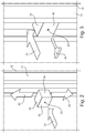
- Figure 2 shows how, according to the arrow 21, an engagement element 13 is inserted in the C-shaped profile of the upright 11. Once the engagement element 13 has been inserted, it is brought to its preselected height or position in the upright, acting according to the directions of the arrows 22.
- Figure 3 shows how, when the desired position for the specific application has been found, the drive key 15 is inserted into the hole 23 of the engagement element 13.
- the possibility of positioning the engagement element 13 as desired makes the system particularly advantageous with respect to systems which provide fixed points and with a discreet number of possible positionings.
- Figure 4 shows the subsequent step in which the drive key 15 positioned in the hole 23 of the engagement element 13, is rotated. This rotation is effected according to the arrows 24 so as to allow the expandable side parts 14 to exit, by means of the inner control mechanism, according to the arrows 27.
- This step and arrangement can be better seen in figures 5 and 9 , where, in particular, in this second figure 9 , the translation and expansion of the expandable side parts 14 can be seen, inside the profile of the upright 11 with engagement between the facing and juxtaposed surfaces of the side parts 14 and inside the profile of the upright 11.
- the drive key 15 is removed.
- the engagement element 13 is therefore stably fixed inside the upright 11 and the first fixing element 16, integral with the same, is facing the outside of the upright 11.
- a supporting element 17 for a cladding element 18 is effected in this position.
- the supporting element 17 provides, constrained to the same, in the surface which is brought to face the engagement element 13, a second fixing element 19, facing inwardly and complementary to the first fixing element 16 of the engagement element 13.
- This application is effected by joining the supporting element 17 with the engagement element 13 according to the arrow 25 of figure 6 and creating a stable union between the two male and female portions of the fixing elements 16 and 19 of the engagement element 13 and supporting element 17, arranged as desired on one or the other, indifferently, provided they are alternating.
- FIG. 7 A stable positioning between the parts is thus created as shown in figure 7 .
- Said figure 7 also shows how the subsequent positioning of a cladding element 18 is effected on a supporting element 17 thus positioned.
- a notch 26 formed beneath the cladding element 18 is stably engaged on a portion of the double-T profile constituting the supporting element 17. In this way, the cladding element 18 is firmly fixed with respect to the exterior wall or surface 12 of a building.
- Figure 10 shows this stable application of the above-mentioned cladding element 18 from a different angle in a perspective view.
- Both the engagement element 13 and the supporting element 17 are provided with a fixing element 16 (male or female as desired) and the other with a complementary fixing element 19 (female or male as desired) arranged integrally with the same in the workshop so as to arrive already ready on site.
- An anchoring and fixing system of cladding materials to an exterior surface of buildings substitutes traditional mechanical fixings through the use of a material based on plastic, metal or of another type which is engaged by means of a part called “female” and another part called “male” positioned indifferently on the engagement element 13 or on the supporting element 17.
- the adhesives, seams or other mechanical and nonmechanical systems for a stable joining between the engagement element 13 and supporting element 17 and complementary fixing elements 16 and 19 are designed so as to be adapted and be such as to be able to carry different kinds of cladding element 18.
- Metallic materials have the advantage of having a modest weight with the possibility of working on large formats. They are also easy to process and can therefore be adapted to the fixing system of the present invention.
- Non-metallic materials having a considerable weight and thickness can be stone materials, concrete, stone, etc.
- the bracket or profile of the supporting element must be suitably sized in relation to the weight of the cladding.
- the cladding element can be easily processed so as to allow an easy and secure anchorage.
- the third materials mentioned above have the advantage of being light, but have a small thickness.
- bracket or supporting element and relative profile to be used can therefore relate to ceramic materials, HPL, Bakelite wood, etc.
- the upright 11 and supporting element 17 of the cladding element 18 is normally a metallic element which is sized for supporting the cladding material and wind thrust.
- the upright preferably has a shaped profile so as to be able to house the above-mentioned engagement element 13 suitably processed, having its fixing element 16, male or female, as preferred, previously described, already identically arranged on the outer face.
- the engagement element 13 therefore has its fixing element 16 already glued or constrained in the workshop, ready to be used on site, and is inserted in the seat of the closed upright 11.
- This key opens the two wings that form a block with the upright 11.
Landscapes
- Engineering & Computer Science (AREA)
- Architecture (AREA)
- Civil Engineering (AREA)
- Structural Engineering (AREA)
- Finishing Walls (AREA)
- Joining Of Building Structures In Genera (AREA)
Claims (9)
- System, das zum Verankern und Befestigen von Verkleidungsmaterialien an der Außenfläche von Gebäuden geeignet ist und das mindestens ein aufrecht stehendes Teil (11) umfasst, das integral mit Bezug auf eine Außenfläche (12) von Gebäuden positioniert ist, wobei das mindestens eine aufrecht stehende Teil (11) so geformt ist, dass es mindestens ein Eingriffnahmeelement (13) aufnehmen kann, das mit einem ersten Befestigungselement (16) versehen ist, wobei das mindestens eine Eingriffnahmeelement (13) dafür geeignet ist, ein gekoppeltes Stützelement (17) aufzunehmen, das ein Verkleidungselement (18) umfasst, wobei das Stützelement (17) mit einem zweiten Befestigungselement (19) versehen ist, wobei das erste und das zweite Befestigungselement (16, 19) unterschiedslos aus mindestens einem Basisabschnitt bestehen, von dem sich entweder Schlaufen oder Haken erstrecken, um ein Aufnahme-Befestigungselement bzw. ein Einschub-Befestigungselement zu bilden,
dadurch gekennzeichnet, dass das mindestens eine Eingriffnahmeelement (13) ein hohles Element bereitstellt, das aufweitbare Seitenteile (14) umfasst, die seitwärts austreten, wenn sie durch einen Befehl (15) linear verschoben werden. - System nach Anspruch 1, dadurch gekennzeichnet, dass das mindestens eine Eingriffnahmeelement (13) ein hohles prismatisches Element ist, das zwei Flügel (14) umfasst, die teleskopisch darin aufgenommen sind und von gegenüberliegenden Teilen der Eingriffnahmeelement (13) aufgeweitet werden können.
- System nach Anspruch 1 oder 2, dadurch gekennzeichnet, dass der Befehl ein Mechanismus im Inneren des Eingriffnahmeelements (13) ist, der mittels eines Antriebsschlüssels (15) betätigt werden kann, der in ein Loch (23) des Eingriffnahmeelements (13) eingeführt werden kann.
- System nach einem oder mehreren der vorangehenden Ansprüche 1 bis 3, dadurch gekennzeichnet, dass einander zugewandte Flächen des aufrecht stehenden Teils (11) und der aufweitbaren Seitenteile (14) des Hakenelements (13) gerändelt oder in jedem Fall nicht glatt sind, um eine stabile Eingriffnahme zwischen den Teilen der Seitenteile (14) zu ermöglichen, wenn ihre lineare Bewegung vollendet wurde.
- System nach einem oder mehreren der vorangehenden Ansprüche 1 bis 4, dadurch gekennzeichnet, dass das Stützelement (17), das ein Verkleidungselement (18) umfasst, ein Doppel-T- oder C-Profil oder ein anderes geeignetes Profil ist.
- System nach einem oder mehreren der vorangehenden Ansprüche 1 bis 5, dadurch gekennzeichnet, dass das mindestens eine aufrecht stehende Teil (11) integral mit der Außenfläche (12) mittels mindestens eines Klemmelements (20) positioniert ist.
- System nach Anspruch 6, dadurch gekennzeichnet, dass das mindestens eine Klemmelement (20) ein Paar L-förmige Sektionen umfasst, die entlang ihrer vertikalen Längsseiten des L kombiniert werden und ein Z bilden.
- System nach einem oder mehreren der vorangehenden Ansprüche 1 bis 7, dadurch gekennzeichnet, dass das erste Befestigungselement (16), das mit Bezug auf das Eingriffnahmeelement (13) integral positioniert ist, aus mindestens einem Basisabschnitt besteht, von dem aus sich Schlaufen erstrecken, und das zweite Befestigungselement (19), das mit dem Stützelement (17) integral ist, aus mindestens einem Basisabschnitt besteht, von dem aus sich Haken erstrecken.
- System nach einem oder mehreren der vorangehenden Ansprüche 1 bis 7, dadurch gekennzeichnet, dass das erste Befestigungselement (16), das mit Bezug auf das Eingriffnahmeelement (13) integral positioniert ist, aus mindestens einem Basisabschnitt besteht, von dem aus sich Haken erstrecken, und das zweite Befestigungselement (19), das mit dem Stützelement (17) integral ist, aus mindestens einem Basisabschnitt besteht, von dem aus sich Schlaufen erstrecken.
Applications Claiming Priority (1)
| Application Number | Priority Date | Filing Date | Title |
|---|---|---|---|
| IT102016000116373A IT201600116373A1 (it) | 2016-11-17 | 2016-11-17 | Sistema di ancoraggio e fissaggio di materiali di rivestimento ad una superficie esterna di edifici |
Publications (2)
| Publication Number | Publication Date |
|---|---|
| EP3323959A1 EP3323959A1 (de) | 2018-05-23 |
| EP3323959B1 true EP3323959B1 (de) | 2019-07-24 |
Family
ID=58266100
Family Applications (1)
| Application Number | Title | Priority Date | Filing Date |
|---|---|---|---|
| EP17200396.4A Not-in-force EP3323959B1 (de) | 2016-11-17 | 2017-11-07 | System zur verankerung und zur befestigung belagselemente auf eine aussenfläche von gebäuden |
Country Status (2)
| Country | Link |
|---|---|
| EP (1) | EP3323959B1 (de) |
| IT (1) | IT201600116373A1 (de) |
Families Citing this family (1)
| Publication number | Priority date | Publication date | Assignee | Title |
|---|---|---|---|---|
| IT201800004430A1 (it) * | 2018-04-12 | 2019-10-12 | Sistema di aggancio e fissaggio di materiali e/o oggetti ad una superficie |
Family Cites Families (6)
| Publication number | Priority date | Publication date | Assignee | Title |
|---|---|---|---|---|
| US2116533A (en) * | 1935-06-01 | 1938-05-10 | Grabler Mfg Company | Building structure |
| US3807112A (en) * | 1972-07-20 | 1974-04-30 | American Velcro Inc | Room structure and panel assembly |
| AU714529B3 (en) * | 1998-08-28 | 2000-01-06 | PCC Holdings Pty Limited | Improvements in cladding panel facade systems for buildings |
| JP2007247382A (ja) * | 2006-02-20 | 2007-09-27 | Masahide Hosoya | パネル取付構造 |
| JP5241170B2 (ja) * | 2007-08-22 | 2013-07-17 | 株式会社川島織物セルコン | 壁装材貼設パネルの取付構造 |
| WO2010052921A1 (ja) * | 2008-11-06 | 2010-05-14 | 株式会社アクト | 建物躯体に外装板を取り付けるためのアンカー金物 |
-
2016
- 2016-11-17 IT IT102016000116373A patent/IT201600116373A1/it unknown
-
2017
- 2017-11-07 EP EP17200396.4A patent/EP3323959B1/de not_active Not-in-force
Non-Patent Citations (1)
| Title |
|---|
| None * |
Also Published As
| Publication number | Publication date |
|---|---|
| IT201600116373A1 (it) | 2018-05-17 |
| EP3323959A1 (de) | 2018-05-23 |
Similar Documents
| Publication | Publication Date | Title |
|---|---|---|
| US5265389A (en) | Composite building panel | |
| KR101521626B1 (ko) | 복합아트패널 제조방법 및 복합아트패널 | |
| US10876299B2 (en) | Fastening system | |
| EP3105388A1 (de) | Vorgefertigtes paneelkonstruktionssystem | |
| EP3323959B1 (de) | System zur verankerung und zur befestigung belagselemente auf eine aussenfläche von gebäuden | |
| CA2988632A1 (en) | Connecting element for wall construction elements | |
| WO2018031506A1 (en) | Triangular stud shaft wall system | |
| KR101614935B1 (ko) | 조립식 경량 패널 | |
| US20190136521A1 (en) | Metal skeleton for the reinforcement of concrete walls and floors | |
| CN203716347U (zh) | 一种扣盖式钢型材玻璃隔断系统 | |
| EP2943621B1 (de) | Verfahren zur herstellung von verbunddeckplatten sowie mit diesem verfahren erhaltene platte | |
| EP2809851B1 (de) | Produkt zur bereitstellung einer wärmedämmung an den aussenseiten eines gebäudes sowie verfahren zu seiner montage | |
| JP2020139313A (ja) | 天井パネル | |
| EP2910706B1 (de) | Montagelement zur beabstandeten Aufhängung einer Fassadenverkleidung an einer Wand eines Gebäudes | |
| GB2139683A (en) | Guide structure for a shutter | |
| CN202899532U (zh) | 低碳板粘卡结合的连接构件 | |
| DK179704B1 (en) | Frame for a wall element | |
| RU123806U1 (ru) | Обрамляющий профиль для потолочных конструкций и угловые элементы для него | |
| Dandona et al. | Construction of diplomatic embassies, post-independence New Delhi | |
| US11976463B1 (en) | Support wall frame system and associated use thereof | |
| AU2023201377B2 (en) | A wall assembly | |
| US20060059793A1 (en) | Quickwall integrated building shell system | |
| CN222810350U (zh) | 一种外墙保温装饰一体板结构、安装结构、节点及建筑 | |
| CN102936949A (zh) | 低碳板粘卡结合的连接构件及其使用安装方法 | |
| Schwinn | Manufacturing perspectives |
Legal Events
| Date | Code | Title | Description |
|---|---|---|---|
| PUAI | Public reference made under article 153(3) epc to a published international application that has entered the european phase |
Free format text: ORIGINAL CODE: 0009012 |
|
| STAA | Information on the status of an ep patent application or granted ep patent |
Free format text: STATUS: THE APPLICATION HAS BEEN PUBLISHED |
|
| AK | Designated contracting states |
Kind code of ref document: A1 Designated state(s): AL AT BE BG CH CY CZ DE DK EE ES FI FR GB GR HR HU IE IS IT LI LT LU LV MC MK MT NL NO PL PT RO RS SE SI SK SM TR |
|
| AX | Request for extension of the european patent |
Extension state: BA ME |
|
| STAA | Information on the status of an ep patent application or granted ep patent |
Free format text: STATUS: REQUEST FOR EXAMINATION WAS MADE |
|
| 17P | Request for examination filed |
Effective date: 20181011 |
|
| RBV | Designated contracting states (corrected) |
Designated state(s): AL AT BE BG CH CY CZ DE DK EE ES FI FR GB GR HR HU IE IS IT LI LT LU LV MC MK MT NL NO PL PT RO RS SE SI SK SM TR |
|
| GRAP | Despatch of communication of intention to grant a patent |
Free format text: ORIGINAL CODE: EPIDOSNIGR1 |
|
| STAA | Information on the status of an ep patent application or granted ep patent |
Free format text: STATUS: GRANT OF PATENT IS INTENDED |
|
| INTG | Intention to grant announced |
Effective date: 20190320 |
|
| GRAS | Grant fee paid |
Free format text: ORIGINAL CODE: EPIDOSNIGR3 |
|
| GRAA | (expected) grant |
Free format text: ORIGINAL CODE: 0009210 |
|
| STAA | Information on the status of an ep patent application or granted ep patent |
Free format text: STATUS: THE PATENT HAS BEEN GRANTED |
|
| AK | Designated contracting states |
Kind code of ref document: B1 Designated state(s): AL AT BE BG CH CY CZ DE DK EE ES FI FR GB GR HR HU IE IS IT LI LT LU LV MC MK MT NL NO PL PT RO RS SE SI SK SM TR |
|
| REG | Reference to a national code |
Ref country code: GB Ref legal event code: FG4D |
|
| REG | Reference to a national code |
Ref country code: CH Ref legal event code: EP |
|
| REG | Reference to a national code |
Ref country code: DE Ref legal event code: R096 Ref document number: 602017005520 Country of ref document: DE |
|
| REG | Reference to a national code |
Ref country code: AT Ref legal event code: REF Ref document number: 1158366 Country of ref document: AT Kind code of ref document: T Effective date: 20190815 |
|
| REG | Reference to a national code |
Ref country code: IE Ref legal event code: FG4D |
|
| REG | Reference to a national code |
Ref country code: CH Ref legal event code: PK Free format text: BERICHTIGUNGEN |
|
| RAP2 | Party data changed (patent owner data changed or rights of a patent transferred) |
Owner name: SYNTHESIS SRL |
|
| RIN2 | Information on inventor provided after grant (corrected) |
Inventor name: BERETTA, ANGELO |
|
| REG | Reference to a national code |
Ref country code: NL Ref legal event code: MP Effective date: 20190724 |
|
| REG | Reference to a national code |
Ref country code: LT Ref legal event code: MG4D |
|
| REG | Reference to a national code |
Ref country code: DE Ref legal event code: R082 Ref document number: 602017005520 Country of ref document: DE Representative=s name: ISARPATENT - PATENT- UND RECHTSANWAELTE BEHNIS, DE Ref country code: DE Ref legal event code: R081 Ref document number: 602017005520 Country of ref document: DE Owner name: SYNTHESIS SRL, IT Free format text: FORMER OWNER: BERETTA, ANGELO, CERNUSCO SUL NAVIGLIO (MI), IT Ref country code: DE Ref legal event code: R082 Ref document number: 602017005520 Country of ref document: DE Representative=s name: ISARPATENT - PATENT- UND RECHTSANWAELTE BARTH , DE |
|
| REG | Reference to a national code |
Ref country code: AT Ref legal event code: MK05 Ref document number: 1158366 Country of ref document: AT Kind code of ref document: T Effective date: 20190724 |
|
| PG25 | Lapsed in a contracting state [announced via postgrant information from national office to epo] |
Ref country code: FI Free format text: LAPSE BECAUSE OF FAILURE TO SUBMIT A TRANSLATION OF THE DESCRIPTION OR TO PAY THE FEE WITHIN THE PRESCRIBED TIME-LIMIT Effective date: 20190724 Ref country code: HR Free format text: LAPSE BECAUSE OF FAILURE TO SUBMIT A TRANSLATION OF THE DESCRIPTION OR TO PAY THE FEE WITHIN THE PRESCRIBED TIME-LIMIT Effective date: 20190724 Ref country code: PT Free format text: LAPSE BECAUSE OF FAILURE TO SUBMIT A TRANSLATION OF THE DESCRIPTION OR TO PAY THE FEE WITHIN THE PRESCRIBED TIME-LIMIT Effective date: 20191125 Ref country code: BG Free format text: LAPSE BECAUSE OF FAILURE TO SUBMIT A TRANSLATION OF THE DESCRIPTION OR TO PAY THE FEE WITHIN THE PRESCRIBED TIME-LIMIT Effective date: 20191024 Ref country code: LT Free format text: LAPSE BECAUSE OF FAILURE TO SUBMIT A TRANSLATION OF THE DESCRIPTION OR TO PAY THE FEE WITHIN THE PRESCRIBED TIME-LIMIT Effective date: 20190724 Ref country code: NL Free format text: LAPSE BECAUSE OF FAILURE TO SUBMIT A TRANSLATION OF THE DESCRIPTION OR TO PAY THE FEE WITHIN THE PRESCRIBED TIME-LIMIT Effective date: 20190724 Ref country code: NO Free format text: LAPSE BECAUSE OF FAILURE TO SUBMIT A TRANSLATION OF THE DESCRIPTION OR TO PAY THE FEE WITHIN THE PRESCRIBED TIME-LIMIT Effective date: 20191024 Ref country code: AT Free format text: LAPSE BECAUSE OF FAILURE TO SUBMIT A TRANSLATION OF THE DESCRIPTION OR TO PAY THE FEE WITHIN THE PRESCRIBED TIME-LIMIT Effective date: 20190724 Ref country code: SE Free format text: LAPSE BECAUSE OF FAILURE TO SUBMIT A TRANSLATION OF THE DESCRIPTION OR TO PAY THE FEE WITHIN THE PRESCRIBED TIME-LIMIT Effective date: 20190724 |
|
| PG25 | Lapsed in a contracting state [announced via postgrant information from national office to epo] |
Ref country code: RS Free format text: LAPSE BECAUSE OF FAILURE TO SUBMIT A TRANSLATION OF THE DESCRIPTION OR TO PAY THE FEE WITHIN THE PRESCRIBED TIME-LIMIT Effective date: 20190724 Ref country code: IS Free format text: LAPSE BECAUSE OF FAILURE TO SUBMIT A TRANSLATION OF THE DESCRIPTION OR TO PAY THE FEE WITHIN THE PRESCRIBED TIME-LIMIT Effective date: 20191124 Ref country code: AL Free format text: LAPSE BECAUSE OF FAILURE TO SUBMIT A TRANSLATION OF THE DESCRIPTION OR TO PAY THE FEE WITHIN THE PRESCRIBED TIME-LIMIT Effective date: 20190724 Ref country code: GR Free format text: LAPSE BECAUSE OF FAILURE TO SUBMIT A TRANSLATION OF THE DESCRIPTION OR TO PAY THE FEE WITHIN THE PRESCRIBED TIME-LIMIT Effective date: 20191025 Ref country code: ES Free format text: LAPSE BECAUSE OF FAILURE TO SUBMIT A TRANSLATION OF THE DESCRIPTION OR TO PAY THE FEE WITHIN THE PRESCRIBED TIME-LIMIT Effective date: 20190724 Ref country code: LV Free format text: LAPSE BECAUSE OF FAILURE TO SUBMIT A TRANSLATION OF THE DESCRIPTION OR TO PAY THE FEE WITHIN THE PRESCRIBED TIME-LIMIT Effective date: 20190724 |
|
| PG25 | Lapsed in a contracting state [announced via postgrant information from national office to epo] |
Ref country code: TR Free format text: LAPSE BECAUSE OF FAILURE TO SUBMIT A TRANSLATION OF THE DESCRIPTION OR TO PAY THE FEE WITHIN THE PRESCRIBED TIME-LIMIT Effective date: 20190724 |
|
| PG25 | Lapsed in a contracting state [announced via postgrant information from national office to epo] |
Ref country code: EE Free format text: LAPSE BECAUSE OF FAILURE TO SUBMIT A TRANSLATION OF THE DESCRIPTION OR TO PAY THE FEE WITHIN THE PRESCRIBED TIME-LIMIT Effective date: 20190724 Ref country code: DK Free format text: LAPSE BECAUSE OF FAILURE TO SUBMIT A TRANSLATION OF THE DESCRIPTION OR TO PAY THE FEE WITHIN THE PRESCRIBED TIME-LIMIT Effective date: 20190724 Ref country code: RO Free format text: LAPSE BECAUSE OF FAILURE TO SUBMIT A TRANSLATION OF THE DESCRIPTION OR TO PAY THE FEE WITHIN THE PRESCRIBED TIME-LIMIT Effective date: 20190724 Ref country code: PL Free format text: LAPSE BECAUSE OF FAILURE TO SUBMIT A TRANSLATION OF THE DESCRIPTION OR TO PAY THE FEE WITHIN THE PRESCRIBED TIME-LIMIT Effective date: 20190724 |
|
| PG25 | Lapsed in a contracting state [announced via postgrant information from national office to epo] |
Ref country code: SK Free format text: LAPSE BECAUSE OF FAILURE TO SUBMIT A TRANSLATION OF THE DESCRIPTION OR TO PAY THE FEE WITHIN THE PRESCRIBED TIME-LIMIT Effective date: 20190724 Ref country code: IS Free format text: LAPSE BECAUSE OF FAILURE TO SUBMIT A TRANSLATION OF THE DESCRIPTION OR TO PAY THE FEE WITHIN THE PRESCRIBED TIME-LIMIT Effective date: 20200224 Ref country code: CZ Free format text: LAPSE BECAUSE OF FAILURE TO SUBMIT A TRANSLATION OF THE DESCRIPTION OR TO PAY THE FEE WITHIN THE PRESCRIBED TIME-LIMIT Effective date: 20190724 Ref country code: SM Free format text: LAPSE BECAUSE OF FAILURE TO SUBMIT A TRANSLATION OF THE DESCRIPTION OR TO PAY THE FEE WITHIN THE PRESCRIBED TIME-LIMIT Effective date: 20190724 |
|
| REG | Reference to a national code |
Ref country code: DE Ref legal event code: R097 Ref document number: 602017005520 Country of ref document: DE |
|
| PLBE | No opposition filed within time limit |
Free format text: ORIGINAL CODE: 0009261 |
|
| STAA | Information on the status of an ep patent application or granted ep patent |
Free format text: STATUS: NO OPPOSITION FILED WITHIN TIME LIMIT |
|
| PG2D | Information on lapse in contracting state deleted |
Ref country code: IS |
|
| PG25 | Lapsed in a contracting state [announced via postgrant information from national office to epo] |
Ref country code: MC Free format text: LAPSE BECAUSE OF FAILURE TO SUBMIT A TRANSLATION OF THE DESCRIPTION OR TO PAY THE FEE WITHIN THE PRESCRIBED TIME-LIMIT Effective date: 20190724 Ref country code: LU Free format text: LAPSE BECAUSE OF NON-PAYMENT OF DUE FEES Effective date: 20191107 |
|
| 26N | No opposition filed |
Effective date: 20200603 |
|
| REG | Reference to a national code |
Ref country code: BE Ref legal event code: MM Effective date: 20191130 |
|
| PG25 | Lapsed in a contracting state [announced via postgrant information from national office to epo] |
Ref country code: SI Free format text: LAPSE BECAUSE OF FAILURE TO SUBMIT A TRANSLATION OF THE DESCRIPTION OR TO PAY THE FEE WITHIN THE PRESCRIBED TIME-LIMIT Effective date: 20190724 |
|
| PG25 | Lapsed in a contracting state [announced via postgrant information from national office to epo] |
Ref country code: IE Free format text: LAPSE BECAUSE OF NON-PAYMENT OF DUE FEES Effective date: 20191107 |
|
| PG25 | Lapsed in a contracting state [announced via postgrant information from national office to epo] |
Ref country code: BE Free format text: LAPSE BECAUSE OF NON-PAYMENT OF DUE FEES Effective date: 20191130 |
|
| PGFP | Annual fee paid to national office [announced via postgrant information from national office to epo] |
Ref country code: DE Payment date: 20201127 Year of fee payment: 4 Ref country code: FR Payment date: 20201125 Year of fee payment: 4 Ref country code: IT Payment date: 20201130 Year of fee payment: 4 |
|
| PG25 | Lapsed in a contracting state [announced via postgrant information from national office to epo] |
Ref country code: CY Free format text: LAPSE BECAUSE OF FAILURE TO SUBMIT A TRANSLATION OF THE DESCRIPTION OR TO PAY THE FEE WITHIN THE PRESCRIBED TIME-LIMIT Effective date: 20190724 |
|
| PG25 | Lapsed in a contracting state [announced via postgrant information from national office to epo] |
Ref country code: LI Free format text: LAPSE BECAUSE OF FAILURE TO SUBMIT A TRANSLATION OF THE DESCRIPTION OR TO PAY THE FEE WITHIN THE PRESCRIBED TIME-LIMIT Effective date: 20201130 Ref country code: CH Free format text: LAPSE BECAUSE OF FAILURE TO SUBMIT A TRANSLATION OF THE DESCRIPTION OR TO PAY THE FEE WITHIN THE PRESCRIBED TIME-LIMIT Effective date: 20201130 |
|
| REG | Reference to a national code |
Ref country code: CH Ref legal event code: PL |
|
| PG25 | Lapsed in a contracting state [announced via postgrant information from national office to epo] |
Ref country code: MT Free format text: LAPSE BECAUSE OF FAILURE TO SUBMIT A TRANSLATION OF THE DESCRIPTION OR TO PAY THE FEE WITHIN THE PRESCRIBED TIME-LIMIT Effective date: 20190724 Ref country code: HU Free format text: LAPSE BECAUSE OF FAILURE TO SUBMIT A TRANSLATION OF THE DESCRIPTION OR TO PAY THE FEE WITHIN THE PRESCRIBED TIME-LIMIT; INVALID AB INITIO Effective date: 20171107 |
|
| REG | Reference to a national code |
Ref country code: DE Ref legal event code: R119 Ref document number: 602017005520 Country of ref document: DE |
|
| PG25 | Lapsed in a contracting state [announced via postgrant information from national office to epo] |
Ref country code: MK Free format text: LAPSE BECAUSE OF FAILURE TO SUBMIT A TRANSLATION OF THE DESCRIPTION OR TO PAY THE FEE WITHIN THE PRESCRIBED TIME-LIMIT Effective date: 20190724 |
|
| GBPC | Gb: european patent ceased through non-payment of renewal fee |
Effective date: 20211107 |
|
| PG25 | Lapsed in a contracting state [announced via postgrant information from national office to epo] |
Ref country code: GB Free format text: LAPSE BECAUSE OF NON-PAYMENT OF DUE FEES Effective date: 20211107 Ref country code: DE Free format text: LAPSE BECAUSE OF NON-PAYMENT OF DUE FEES Effective date: 20220601 |
|
| PG25 | Lapsed in a contracting state [announced via postgrant information from national office to epo] |
Ref country code: FR Free format text: LAPSE BECAUSE OF NON-PAYMENT OF DUE FEES Effective date: 20211130 |
|
| PG25 | Lapsed in a contracting state [announced via postgrant information from national office to epo] |
Ref country code: IT Free format text: LAPSE BECAUSE OF NON-PAYMENT OF DUE FEES Effective date: 20211107 |