EP3322010B1 - Method for manufacturing electrode collector for secondary battery - Google Patents
Method for manufacturing electrode collector for secondary battery Download PDFInfo
- Publication number
- EP3322010B1 EP3322010B1 EP17770534.0A EP17770534A EP3322010B1 EP 3322010 B1 EP3322010 B1 EP 3322010B1 EP 17770534 A EP17770534 A EP 17770534A EP 3322010 B1 EP3322010 B1 EP 3322010B1
- Authority
- EP
- European Patent Office
- Prior art keywords
- cnt
- coating layer
- current collector
- metal foil
- electrode
- Prior art date
- Legal status (The legal status is an assumption and is not a legal conclusion. Google has not performed a legal analysis and makes no representation as to the accuracy of the status listed.)
- Active
Links
- 238000000034 method Methods 0.000 title claims description 44
- 238000004519 manufacturing process Methods 0.000 title claims description 29
- OKTJSMMVPCPJKN-UHFFFAOYSA-N Carbon Chemical compound [C] OKTJSMMVPCPJKN-UHFFFAOYSA-N 0.000 claims description 122
- 239000002041 carbon nanotube Substances 0.000 claims description 111
- 229910021393 carbon nanotube Inorganic materials 0.000 claims description 107
- 239000011247 coating layer Substances 0.000 claims description 59
- 239000011888 foil Substances 0.000 claims description 44
- XLYOFNOQVPJJNP-UHFFFAOYSA-N water Substances O XLYOFNOQVPJJNP-UHFFFAOYSA-N 0.000 claims description 44
- 229910052751 metal Inorganic materials 0.000 claims description 39
- 239000002184 metal Substances 0.000 claims description 39
- 239000006185 dispersion Substances 0.000 claims description 25
- 239000000203 mixture Substances 0.000 claims description 22
- 239000002238 carbon nanotube film Substances 0.000 claims description 19
- 239000011267 electrode slurry Substances 0.000 claims description 17
- 239000002904 solvent Substances 0.000 claims description 14
- 239000010410 layer Substances 0.000 claims description 13
- WEVYAHXRMPXWCK-UHFFFAOYSA-N Acetonitrile Chemical compound CC#N WEVYAHXRMPXWCK-UHFFFAOYSA-N 0.000 claims description 9
- 239000012153 distilled water Substances 0.000 claims description 5
- 238000003825 pressing Methods 0.000 claims description 5
- 238000005507 spraying Methods 0.000 claims description 5
- CSCPPACGZOOCGX-UHFFFAOYSA-N Acetone Chemical compound CC(C)=O CSCPPACGZOOCGX-UHFFFAOYSA-N 0.000 claims description 4
- LFQSCWFLJHTTHZ-UHFFFAOYSA-N Ethanol Chemical compound CCO LFQSCWFLJHTTHZ-UHFFFAOYSA-N 0.000 claims description 4
- 238000010438 heat treatment Methods 0.000 claims description 4
- 239000000463 material Substances 0.000 claims description 4
- 238000001035 drying Methods 0.000 claims description 2
- 239000004020 conductor Substances 0.000 description 22
- WHXSMMKQMYFTQS-UHFFFAOYSA-N Lithium Chemical compound [Li] WHXSMMKQMYFTQS-UHFFFAOYSA-N 0.000 description 20
- 229910052744 lithium Inorganic materials 0.000 description 20
- -1 ethanol and the like Chemical compound 0.000 description 17
- 230000000052 comparative effect Effects 0.000 description 15
- 239000011149 active material Substances 0.000 description 13
- 230000008569 process Effects 0.000 description 13
- RYGMFSIKBFXOCR-UHFFFAOYSA-N Copper Chemical compound [Cu] RYGMFSIKBFXOCR-UHFFFAOYSA-N 0.000 description 12
- 239000011230 binding agent Substances 0.000 description 12
- 239000007772 electrode material Substances 0.000 description 11
- 238000012546 transfer Methods 0.000 description 11
- 238000000576 coating method Methods 0.000 description 10
- 230000006866 deterioration Effects 0.000 description 8
- 229920000642 polymer Polymers 0.000 description 8
- 239000011248 coating agent Substances 0.000 description 7
- 239000010949 copper Substances 0.000 description 7
- 230000003247 decreasing effect Effects 0.000 description 7
- 239000011255 nonaqueous electrolyte Substances 0.000 description 7
- SECXISVLQFMRJM-UHFFFAOYSA-N N-Methylpyrrolidone Chemical compound CN1CCCC1=O SECXISVLQFMRJM-UHFFFAOYSA-N 0.000 description 6
- 239000002033 PVDF binder Substances 0.000 description 6
- 239000003792 electrolyte Substances 0.000 description 6
- 239000007773 negative electrode material Substances 0.000 description 6
- 229920002981 polyvinylidene fluoride Polymers 0.000 description 6
- 239000007774 positive electrode material Substances 0.000 description 6
- 239000002002 slurry Substances 0.000 description 6
- PXHVJJICTQNCMI-UHFFFAOYSA-N Nickel Chemical compound [Ni] PXHVJJICTQNCMI-UHFFFAOYSA-N 0.000 description 5
- 239000004698 Polyethylene Substances 0.000 description 5
- 239000000945 filler Substances 0.000 description 5
- 229910003002 lithium salt Inorganic materials 0.000 description 5
- 159000000002 lithium salts Chemical class 0.000 description 5
- 230000014759 maintenance of location Effects 0.000 description 5
- 229920000573 polyethylene Polymers 0.000 description 5
- 239000007784 solid electrolyte Substances 0.000 description 5
- 239000000126 substance Substances 0.000 description 5
- 239000004743 Polypropylene Substances 0.000 description 4
- XAGFODPZIPBFFR-UHFFFAOYSA-N aluminium Chemical compound [Al] XAGFODPZIPBFFR-UHFFFAOYSA-N 0.000 description 4
- 229910052802 copper Inorganic materials 0.000 description 4
- 238000003618 dip coating Methods 0.000 description 4
- 238000007599 discharging Methods 0.000 description 4
- 229910002804 graphite Inorganic materials 0.000 description 4
- 239000010439 graphite Substances 0.000 description 4
- 230000006872 improvement Effects 0.000 description 4
- 229920001155 polypropylene Polymers 0.000 description 4
- 230000009467 reduction Effects 0.000 description 4
- 229920000049 Carbon (fiber) Polymers 0.000 description 3
- OIFBSDVPJOWBCH-UHFFFAOYSA-N Diethyl carbonate Chemical compound CCOC(=O)OCC OIFBSDVPJOWBCH-UHFFFAOYSA-N 0.000 description 3
- RTZKZFJDLAIYFH-UHFFFAOYSA-N Diethyl ether Chemical compound CCOCC RTZKZFJDLAIYFH-UHFFFAOYSA-N 0.000 description 3
- KMTRUDSVKNLOMY-UHFFFAOYSA-N Ethylene carbonate Chemical compound O=C1OCCO1 KMTRUDSVKNLOMY-UHFFFAOYSA-N 0.000 description 3
- ZMXDDKWLCZADIW-UHFFFAOYSA-N N,N-Dimethylformamide Chemical compound CN(C)C=O ZMXDDKWLCZADIW-UHFFFAOYSA-N 0.000 description 3
- 229910052782 aluminium Inorganic materials 0.000 description 3
- 230000015572 biosynthetic process Effects 0.000 description 3
- 229910052799 carbon Inorganic materials 0.000 description 3
- 239000004917 carbon fiber Substances 0.000 description 3
- 239000003575 carbonaceous material Substances 0.000 description 3
- 238000009792 diffusion process Methods 0.000 description 3
- 230000000694 effects Effects 0.000 description 3
- 238000000157 electrochemical-induced impedance spectroscopy Methods 0.000 description 3
- 238000005530 etching Methods 0.000 description 3
- 239000010408 film Substances 0.000 description 3
- 238000005259 measurement Methods 0.000 description 3
- WNXJIVFYUVYPPR-UHFFFAOYSA-N 1,3-dioxolane Chemical compound C1COCO1 WNXJIVFYUVYPPR-UHFFFAOYSA-N 0.000 description 2
- YEJRWHAVMIAJKC-UHFFFAOYSA-N 4-Butyrolactone Chemical compound O=C1CCCO1 YEJRWHAVMIAJKC-UHFFFAOYSA-N 0.000 description 2
- CURLTUGMZLYLDI-UHFFFAOYSA-N Carbon dioxide Chemical compound O=C=O CURLTUGMZLYLDI-UHFFFAOYSA-N 0.000 description 2
- XTHFKEDIFFGKHM-UHFFFAOYSA-N Dimethoxyethane Chemical compound COCCOC XTHFKEDIFFGKHM-UHFFFAOYSA-N 0.000 description 2
- IAZDPXIOMUYVGZ-UHFFFAOYSA-N Dimethylsulphoxide Chemical compound CS(C)=O IAZDPXIOMUYVGZ-UHFFFAOYSA-N 0.000 description 2
- 229920002943 EPDM rubber Polymers 0.000 description 2
- ZHNUHDYFZUAESO-UHFFFAOYSA-N Formamide Chemical compound NC=O ZHNUHDYFZUAESO-UHFFFAOYSA-N 0.000 description 2
- 229910001290 LiPF6 Inorganic materials 0.000 description 2
- HBBGRARXTFLTSG-UHFFFAOYSA-N Lithium ion Chemical compound [Li+] HBBGRARXTFLTSG-UHFFFAOYSA-N 0.000 description 2
- 229920003171 Poly (ethylene oxide) Polymers 0.000 description 2
- 239000004372 Polyvinyl alcohol Substances 0.000 description 2
- JUJWROOIHBZHMG-UHFFFAOYSA-N Pyridine Chemical compound C1=CC=NC=C1 JUJWROOIHBZHMG-UHFFFAOYSA-N 0.000 description 2
- KAESVJOAVNADME-UHFFFAOYSA-N Pyrrole Chemical class C=1C=CNC=1 KAESVJOAVNADME-UHFFFAOYSA-N 0.000 description 2
- RTAQQCXQSZGOHL-UHFFFAOYSA-N Titanium Chemical compound [Ti] RTAQQCXQSZGOHL-UHFFFAOYSA-N 0.000 description 2
- XLOMVQKBTHCTTD-UHFFFAOYSA-N Zinc monoxide Chemical compound [Zn]=O XLOMVQKBTHCTTD-UHFFFAOYSA-N 0.000 description 2
- 239000006230 acetylene black Substances 0.000 description 2
- 239000000654 additive Substances 0.000 description 2
- 230000000996 additive effect Effects 0.000 description 2
- 150000001336 alkenes Chemical class 0.000 description 2
- 229910021383 artificial graphite Inorganic materials 0.000 description 2
- FFBHFFJDDLITSX-UHFFFAOYSA-N benzyl N-[2-hydroxy-4-(3-oxomorpholin-4-yl)phenyl]carbamate Chemical compound OC1=C(NC(=O)OCC2=CC=CC=C2)C=CC(=C1)N1CCOCC1=O FFBHFFJDDLITSX-UHFFFAOYSA-N 0.000 description 2
- 125000004432 carbon atom Chemical group C* 0.000 description 2
- 230000008859 change Effects 0.000 description 2
- 238000007607 die coating method Methods 0.000 description 2
- 239000000428 dust Substances 0.000 description 2
- 238000005516 engineering process Methods 0.000 description 2
- FKRCODPIKNYEAC-UHFFFAOYSA-N ethyl propionate Chemical compound CCOC(=O)CC FKRCODPIKNYEAC-UHFFFAOYSA-N 0.000 description 2
- LYCAIKOWRPUZTN-UHFFFAOYSA-N ethylene glycol Natural products OCCO LYCAIKOWRPUZTN-UHFFFAOYSA-N 0.000 description 2
- 239000002657 fibrous material Substances 0.000 description 2
- 239000003365 glass fiber Substances 0.000 description 2
- 229910021389 graphene Inorganic materials 0.000 description 2
- 125000001449 isopropyl group Chemical group [H]C([H])([H])C([H])(*)C([H])([H])[H] 0.000 description 2
- AMXOYNBUYSYVKV-UHFFFAOYSA-M lithium bromide Chemical compound [Li+].[Br-] AMXOYNBUYSYVKV-UHFFFAOYSA-M 0.000 description 2
- KWGKDLIKAYFUFQ-UHFFFAOYSA-M lithium chloride Chemical compound [Li+].[Cl-] KWGKDLIKAYFUFQ-UHFFFAOYSA-M 0.000 description 2
- 229910001416 lithium ion Inorganic materials 0.000 description 2
- VNWKTOKETHGBQD-UHFFFAOYSA-N methane Chemical compound C VNWKTOKETHGBQD-UHFFFAOYSA-N 0.000 description 2
- TZIHFWKZFHZASV-UHFFFAOYSA-N methyl formate Chemical compound COC=O TZIHFWKZFHZASV-UHFFFAOYSA-N 0.000 description 2
- 229910021382 natural graphite Inorganic materials 0.000 description 2
- 229910052759 nickel Inorganic materials 0.000 description 2
- 239000004745 nonwoven fabric Substances 0.000 description 2
- JRZJOMJEPLMPRA-UHFFFAOYSA-N olefin Natural products CCCCCCCC=C JRZJOMJEPLMPRA-UHFFFAOYSA-N 0.000 description 2
- 239000002245 particle Substances 0.000 description 2
- 229920005596 polymer binder Polymers 0.000 description 2
- 239000002491 polymer binding agent Substances 0.000 description 2
- 229920002451 polyvinyl alcohol Polymers 0.000 description 2
- 239000011148 porous material Substances 0.000 description 2
- 239000000843 powder Substances 0.000 description 2
- RUOJZAUFBMNUDX-UHFFFAOYSA-N propylene carbonate Chemical compound CC1COC(=O)O1 RUOJZAUFBMNUDX-UHFFFAOYSA-N 0.000 description 2
- 239000000243 solution Substances 0.000 description 2
- 239000010935 stainless steel Substances 0.000 description 2
- 229910001220 stainless steel Inorganic materials 0.000 description 2
- 229920003048 styrene butadiene rubber Polymers 0.000 description 2
- VZGDMQKNWNREIO-UHFFFAOYSA-N tetrachloromethane Chemical compound ClC(Cl)(Cl)Cl VZGDMQKNWNREIO-UHFFFAOYSA-N 0.000 description 2
- 229910052719 titanium Inorganic materials 0.000 description 2
- 239000010936 titanium Substances 0.000 description 2
- PYOKUURKVVELLB-UHFFFAOYSA-N trimethyl orthoformate Chemical compound COC(OC)OC PYOKUURKVVELLB-UHFFFAOYSA-N 0.000 description 2
- MIZLGWKEZAPEFJ-UHFFFAOYSA-N 1,1,2-trifluoroethene Chemical compound FC=C(F)F MIZLGWKEZAPEFJ-UHFFFAOYSA-N 0.000 description 1
- ZZXUZKXVROWEIF-UHFFFAOYSA-N 1,2-butylene carbonate Chemical compound CCC1COC(=O)O1 ZZXUZKXVROWEIF-UHFFFAOYSA-N 0.000 description 1
- LZDKZFUFMNSQCJ-UHFFFAOYSA-N 1,2-diethoxyethane Chemical compound CCOCCOCC LZDKZFUFMNSQCJ-UHFFFAOYSA-N 0.000 description 1
- CYSGHNMQYZDMIA-UHFFFAOYSA-N 1,3-Dimethyl-2-imidazolidinon Chemical compound CN1CCN(C)C1=O CYSGHNMQYZDMIA-UHFFFAOYSA-N 0.000 description 1
- XNWFRZJHXBZDAG-UHFFFAOYSA-N 2-METHOXYETHANOL Chemical class COCCO XNWFRZJHXBZDAG-UHFFFAOYSA-N 0.000 description 1
- JWUJQDFVADABEY-UHFFFAOYSA-N 2-methyltetrahydrofuran Chemical compound CC1CCCO1 JWUJQDFVADABEY-UHFFFAOYSA-N 0.000 description 1
- PPDFQRAASCRJAH-UHFFFAOYSA-N 2-methylthiolane 1,1-dioxide Chemical compound CC1CCCS1(=O)=O PPDFQRAASCRJAH-UHFFFAOYSA-N 0.000 description 1
- BTBUEUYNUDRHOZ-UHFFFAOYSA-N Borate Chemical compound [O-]B([O-])[O-] BTBUEUYNUDRHOZ-UHFFFAOYSA-N 0.000 description 1
- 229910001558 CF3SO3Li Inorganic materials 0.000 description 1
- 239000006245 Carbon black Super-P Substances 0.000 description 1
- 229920002134 Carboxymethyl cellulose Polymers 0.000 description 1
- 229910000925 Cd alloy Inorganic materials 0.000 description 1
- 229920013683 Celanese Polymers 0.000 description 1
- LCGLNKUTAGEVQW-UHFFFAOYSA-N Dimethyl ether Chemical group COC LCGLNKUTAGEVQW-UHFFFAOYSA-N 0.000 description 1
- PIICEJLVQHRZGT-UHFFFAOYSA-N Ethylenediamine Chemical compound NCCN PIICEJLVQHRZGT-UHFFFAOYSA-N 0.000 description 1
- YCKRFDGAMUMZLT-UHFFFAOYSA-N Fluorine atom Chemical compound [F] YCKRFDGAMUMZLT-UHFFFAOYSA-N 0.000 description 1
- 229920002153 Hydroxypropyl cellulose Polymers 0.000 description 1
- 229910004170 Li(NiaCObMnc)O2 Inorganic materials 0.000 description 1
- 229910004176 Li(NiaCObMnc)O4 Inorganic materials 0.000 description 1
- 229910013303 LiB10 Inorganic materials 0.000 description 1
- 229910000552 LiCF3SO3 Inorganic materials 0.000 description 1
- 229910012711 LiCo1-yMnyO2 Inorganic materials 0.000 description 1
- 229910012955 LiCo1−yMnyO2 Inorganic materials 0.000 description 1
- 229910032387 LiCoO2 Inorganic materials 0.000 description 1
- 229910014376 LiMn2-zCozO4 Inorganic materials 0.000 description 1
- 229910014370 LiMn2-zNizO4 Inorganic materials 0.000 description 1
- 229910014554 LiMn2−zCozO4 Inorganic materials 0.000 description 1
- 229910014552 LiMn2−zNizO4 Inorganic materials 0.000 description 1
- 229910002993 LiMnO2 Inorganic materials 0.000 description 1
- 229910002992 LiNi0.33Mn0.33Co0.33O2 Inorganic materials 0.000 description 1
- 229910014167 LiNi1-YCOYO2 Inorganic materials 0.000 description 1
- 229910014380 LiNi1-yMnyO2 Inorganic materials 0.000 description 1
- 229910014940 LiNi1−yCoyO2 Inorganic materials 0.000 description 1
- 229910014946 LiNi1−yMnyO2 Inorganic materials 0.000 description 1
- 229910003005 LiNiO2 Inorganic materials 0.000 description 1
- 229910002097 Lithium manganese(III,IV) oxide Inorganic materials 0.000 description 1
- KDXKERNSBIXSRK-UHFFFAOYSA-N Lysine Natural products NCCCCC(N)C(O)=O KDXKERNSBIXSRK-UHFFFAOYSA-N 0.000 description 1
- 239000004472 Lysine Substances 0.000 description 1
- 229920000914 Metallic fiber Polymers 0.000 description 1
- ZHGDJTMNXSOQDT-UHFFFAOYSA-N NP(N)(N)=O.NP(N)(N)=O.NP(N)(N)=O.NP(N)(N)=O.NP(N)(N)=O.NP(N)(N)=O Chemical compound NP(N)(N)=O.NP(N)(N)=O.NP(N)(N)=O.NP(N)(N)=O.NP(N)(N)=O.NP(N)(N)=O ZHGDJTMNXSOQDT-UHFFFAOYSA-N 0.000 description 1
- 229920000265 Polyparaphenylene Polymers 0.000 description 1
- XBDQKXXYIPTUBI-UHFFFAOYSA-M Propionate Chemical compound CCC([O-])=O XBDQKXXYIPTUBI-UHFFFAOYSA-M 0.000 description 1
- BLRPTPMANUNPDV-UHFFFAOYSA-N Silane Chemical compound [SiH4] BLRPTPMANUNPDV-UHFFFAOYSA-N 0.000 description 1
- BQCADISMDOOEFD-UHFFFAOYSA-N Silver Chemical compound [Ag] BQCADISMDOOEFD-UHFFFAOYSA-N 0.000 description 1
- 229920002472 Starch Polymers 0.000 description 1
- 229910000831 Steel Inorganic materials 0.000 description 1
- 239000002174 Styrene-butadiene Substances 0.000 description 1
- NINIDFKCEFEMDL-UHFFFAOYSA-N Sulfur Chemical compound [S] NINIDFKCEFEMDL-UHFFFAOYSA-N 0.000 description 1
- UCKMPCXJQFINFW-UHFFFAOYSA-N Sulphide Chemical compound [S-2] UCKMPCXJQFINFW-UHFFFAOYSA-N 0.000 description 1
- WYURNTSHIVDZCO-UHFFFAOYSA-N Tetrahydrofuran Chemical class C1CCOC1 WYURNTSHIVDZCO-UHFFFAOYSA-N 0.000 description 1
- GWEVSGVZZGPLCZ-UHFFFAOYSA-N Titan oxide Chemical compound O=[Ti]=O GWEVSGVZZGPLCZ-UHFFFAOYSA-N 0.000 description 1
- GSEJCLTVZPLZKY-UHFFFAOYSA-N Triethanolamine Chemical compound OCCN(CCO)CCO GSEJCLTVZPLZKY-UHFFFAOYSA-N 0.000 description 1
- BEKPOUATRPPTLV-UHFFFAOYSA-N [Li].BCl Chemical compound [Li].BCl BEKPOUATRPPTLV-UHFFFAOYSA-N 0.000 description 1
- 230000002159 abnormal effect Effects 0.000 description 1
- KXKVLQRXCPHEJC-UHFFFAOYSA-N acetic acid trimethyl ester Natural products COC(C)=O KXKVLQRXCPHEJC-UHFFFAOYSA-N 0.000 description 1
- 239000004840 adhesive resin Substances 0.000 description 1
- 229920006223 adhesive resin Polymers 0.000 description 1
- 238000013019 agitation Methods 0.000 description 1
- 150000001298 alcohols Chemical class 0.000 description 1
- 150000007933 aliphatic carboxylic acids Chemical class 0.000 description 1
- 229910000147 aluminium phosphate Inorganic materials 0.000 description 1
- VSCWAEJMTAWNJL-UHFFFAOYSA-K aluminium trichloride Chemical class Cl[Al](Cl)Cl VSCWAEJMTAWNJL-UHFFFAOYSA-K 0.000 description 1
- 150000003863 ammonium salts Chemical class 0.000 description 1
- 230000008901 benefit Effects 0.000 description 1
- 239000006229 carbon black Substances 0.000 description 1
- 229910002092 carbon dioxide Inorganic materials 0.000 description 1
- 239000001569 carbon dioxide Substances 0.000 description 1
- 239000002388 carbon-based active material Substances 0.000 description 1
- 239000006231 channel black Substances 0.000 description 1
- 238000010924 continuous production Methods 0.000 description 1
- 229920001577 copolymer Polymers 0.000 description 1
- 239000007822 coupling agent Substances 0.000 description 1
- 239000002180 crystalline carbon material Substances 0.000 description 1
- 150000004292 cyclic ethers Chemical class 0.000 description 1
- 238000011161 development Methods 0.000 description 1
- 229960004132 diethyl ether Drugs 0.000 description 1
- IEJIGPNLZYLLBP-UHFFFAOYSA-N dimethyl carbonate Chemical compound COC(=O)OC IEJIGPNLZYLLBP-UHFFFAOYSA-N 0.000 description 1
- 150000004862 dioxolanes Chemical class 0.000 description 1
- NJLLQSBAHIKGKF-UHFFFAOYSA-N dipotassium dioxido(oxo)titanium Chemical compound [K+].[K+].[O-][Ti]([O-])=O NJLLQSBAHIKGKF-UHFFFAOYSA-N 0.000 description 1
- 238000010494 dissociation reaction Methods 0.000 description 1
- 230000005593 dissociations Effects 0.000 description 1
- 238000009826 distribution Methods 0.000 description 1
- 229920001971 elastomer Polymers 0.000 description 1
- 238000003487 electrochemical reaction Methods 0.000 description 1
- JBTWLSYIZRCDFO-UHFFFAOYSA-N ethyl methyl carbonate Chemical compound CCOC(=O)OC JBTWLSYIZRCDFO-UHFFFAOYSA-N 0.000 description 1
- 238000011156 evaluation Methods 0.000 description 1
- 238000002474 experimental method Methods 0.000 description 1
- 239000000835 fiber Substances 0.000 description 1
- 238000007667 floating Methods 0.000 description 1
- 239000011737 fluorine Substances 0.000 description 1
- 229910052731 fluorine Inorganic materials 0.000 description 1
- 239000006260 foam Substances 0.000 description 1
- 239000006232 furnace black Substances 0.000 description 1
- 229910021469 graphitizable carbon Inorganic materials 0.000 description 1
- 229910052736 halogen Inorganic materials 0.000 description 1
- 150000002367 halogens Chemical class 0.000 description 1
- 229910021385 hard carbon Inorganic materials 0.000 description 1
- 239000001863 hydroxypropyl cellulose Substances 0.000 description 1
- 235000010977 hydroxypropyl cellulose Nutrition 0.000 description 1
- 150000002461 imidazolidines Chemical class 0.000 description 1
- 150000003949 imides Chemical class 0.000 description 1
- 229910003480 inorganic solid Inorganic materials 0.000 description 1
- 230000010220 ion permeability Effects 0.000 description 1
- 230000001788 irregular Effects 0.000 description 1
- 239000003273 ketjen black Substances 0.000 description 1
- 239000002655 kraft paper Substances 0.000 description 1
- 239000006233 lamp black Substances 0.000 description 1
- 229910001547 lithium hexafluoroantimonate(V) Inorganic materials 0.000 description 1
- 229910001540 lithium hexafluoroarsenate(V) Inorganic materials 0.000 description 1
- MHCFAGZWMAWTNR-UHFFFAOYSA-M lithium perchlorate Chemical compound [Li+].[O-]Cl(=O)(=O)=O MHCFAGZWMAWTNR-UHFFFAOYSA-M 0.000 description 1
- 229910001486 lithium perchlorate Inorganic materials 0.000 description 1
- 229910001537 lithium tetrachloroaluminate Inorganic materials 0.000 description 1
- 229910001496 lithium tetrafluoroborate Inorganic materials 0.000 description 1
- 229910021437 lithium-transition metal oxide Inorganic materials 0.000 description 1
- HSFDLPWPRRSVSM-UHFFFAOYSA-M lithium;2,2,2-trifluoroacetate Chemical compound [Li+].[O-]C(=O)C(F)(F)F HSFDLPWPRRSVSM-UHFFFAOYSA-M 0.000 description 1
- 239000011302 mesophase pitch Substances 0.000 description 1
- 229910044991 metal oxide Inorganic materials 0.000 description 1
- 150000004706 metal oxides Chemical class 0.000 description 1
- 229940017219 methyl propionate Drugs 0.000 description 1
- 239000011325 microbead Substances 0.000 description 1
- 230000005012 migration Effects 0.000 description 1
- 238000013508 migration Methods 0.000 description 1
- 239000012046 mixed solvent Substances 0.000 description 1
- 238000002156 mixing Methods 0.000 description 1
- 150000005181 nitrobenzenes Chemical class 0.000 description 1
- LYGJENNIWJXYER-UHFFFAOYSA-N nitromethane Chemical compound C[N+]([O-])=O LYGJENNIWJXYER-UHFFFAOYSA-N 0.000 description 1
- 229910021470 non-graphitizable carbon Inorganic materials 0.000 description 1
- 239000000615 nonconductor Substances 0.000 description 1
- 239000003960 organic solvent Substances 0.000 description 1
- NBIIXXVUZAFLBC-UHFFFAOYSA-N phosphoric acid Substances OP(O)(O)=O NBIIXXVUZAFLBC-UHFFFAOYSA-N 0.000 description 1
- 150000003014 phosphoric acid esters Chemical class 0.000 description 1
- 229920002239 polyacrylonitrile Polymers 0.000 description 1
- 229920000728 polyester Polymers 0.000 description 1
- 239000005518 polymer electrolyte Substances 0.000 description 1
- 229920000098 polyolefin Polymers 0.000 description 1
- 229920001451 polypropylene glycol Polymers 0.000 description 1
- 229920000036 polyvinylpyrrolidone Polymers 0.000 description 1
- 239000001267 polyvinylpyrrolidone Substances 0.000 description 1
- 235000013855 polyvinylpyrrolidone Nutrition 0.000 description 1
- UMJSCPRVCHMLSP-UHFFFAOYSA-N pyridine Natural products COC1=CC=CN=C1 UMJSCPRVCHMLSP-UHFFFAOYSA-N 0.000 description 1
- 239000001008 quinone-imine dye Substances 0.000 description 1
- 239000004627 regenerated cellulose Substances 0.000 description 1
- 239000005060 rubber Substances 0.000 description 1
- 229910000077 silane Inorganic materials 0.000 description 1
- 229910052709 silver Inorganic materials 0.000 description 1
- 239000004332 silver Substances 0.000 description 1
- 239000002356 single layer Substances 0.000 description 1
- 229910021384 soft carbon Inorganic materials 0.000 description 1
- 239000008107 starch Substances 0.000 description 1
- 235000019698 starch Nutrition 0.000 description 1
- 239000010959 steel Substances 0.000 description 1
- 238000003860 storage Methods 0.000 description 1
- HXJUTPCZVOIRIF-UHFFFAOYSA-N sulfolane Chemical compound O=S1(=O)CCCC1 HXJUTPCZVOIRIF-UHFFFAOYSA-N 0.000 description 1
- 229920005608 sulfonated EPDM Polymers 0.000 description 1
- 229910052717 sulfur Inorganic materials 0.000 description 1
- 239000011593 sulfur Substances 0.000 description 1
- BFKJFAAPBSQJPD-UHFFFAOYSA-N tetrafluoroethene Chemical group FC(F)=C(F)F BFKJFAAPBSQJPD-UHFFFAOYSA-N 0.000 description 1
- TXEYQDLBPFQVAA-UHFFFAOYSA-N tetrafluoromethane Chemical compound FC(F)(F)F TXEYQDLBPFQVAA-UHFFFAOYSA-N 0.000 description 1
- 239000006234 thermal black Substances 0.000 description 1
- 239000010409 thin film Substances 0.000 description 1
- OGIDPMRJRNCKJF-UHFFFAOYSA-N titanium oxide Inorganic materials [Ti]=O OGIDPMRJRNCKJF-UHFFFAOYSA-N 0.000 description 1
- BDZBKCUKTQZUTL-UHFFFAOYSA-N triethyl phosphite Chemical compound CCOP(OCC)OCC BDZBKCUKTQZUTL-UHFFFAOYSA-N 0.000 description 1
- 239000011787 zinc oxide Substances 0.000 description 1
Images


Classifications
-
- H—ELECTRICITY
- H01—ELECTRIC ELEMENTS
- H01M—PROCESSES OR MEANS, e.g. BATTERIES, FOR THE DIRECT CONVERSION OF CHEMICAL ENERGY INTO ELECTRICAL ENERGY
- H01M4/00—Electrodes
- H01M4/02—Electrodes composed of, or comprising, active material
- H01M4/64—Carriers or collectors
- H01M4/66—Selection of materials
- H01M4/665—Composites
- H01M4/667—Composites in the form of layers, e.g. coatings
-
- C—CHEMISTRY; METALLURGY
- C01—INORGANIC CHEMISTRY
- C01B—NON-METALLIC ELEMENTS; COMPOUNDS THEREOF; METALLOIDS OR COMPOUNDS THEREOF NOT COVERED BY SUBCLASS C01C
- C01B32/00—Carbon; Compounds thereof
- C01B32/15—Nano-sized carbon materials
- C01B32/158—Carbon nanotubes
- C01B32/168—After-treatment
- C01B32/174—Derivatisation; Solubilisation; Dispersion in solvents
-
- H—ELECTRICITY
- H01—ELECTRIC ELEMENTS
- H01M—PROCESSES OR MEANS, e.g. BATTERIES, FOR THE DIRECT CONVERSION OF CHEMICAL ENERGY INTO ELECTRICAL ENERGY
- H01M10/00—Secondary cells; Manufacture thereof
- H01M10/05—Accumulators with non-aqueous electrolyte
- H01M10/052—Li-accumulators
- H01M10/0525—Rocking-chair batteries, i.e. batteries with lithium insertion or intercalation in both electrodes; Lithium-ion batteries
-
- H—ELECTRICITY
- H01—ELECTRIC ELEMENTS
- H01M—PROCESSES OR MEANS, e.g. BATTERIES, FOR THE DIRECT CONVERSION OF CHEMICAL ENERGY INTO ELECTRICAL ENERGY
- H01M4/00—Electrodes
- H01M4/02—Electrodes composed of, or comprising, active material
- H01M4/04—Processes of manufacture in general
-
- H—ELECTRICITY
- H01—ELECTRIC ELEMENTS
- H01M—PROCESSES OR MEANS, e.g. BATTERIES, FOR THE DIRECT CONVERSION OF CHEMICAL ENERGY INTO ELECTRICAL ENERGY
- H01M4/00—Electrodes
- H01M4/02—Electrodes composed of, or comprising, active material
- H01M4/04—Processes of manufacture in general
- H01M4/0402—Methods of deposition of the material
- H01M4/0404—Methods of deposition of the material by coating on electrode collectors
-
- H—ELECTRICITY
- H01—ELECTRIC ELEMENTS
- H01M—PROCESSES OR MEANS, e.g. BATTERIES, FOR THE DIRECT CONVERSION OF CHEMICAL ENERGY INTO ELECTRICAL ENERGY
- H01M4/00—Electrodes
- H01M4/02—Electrodes composed of, or comprising, active material
- H01M4/04—Processes of manufacture in general
- H01M4/0402—Methods of deposition of the material
- H01M4/0419—Methods of deposition of the material involving spraying
-
- H—ELECTRICITY
- H01—ELECTRIC ELEMENTS
- H01M—PROCESSES OR MEANS, e.g. BATTERIES, FOR THE DIRECT CONVERSION OF CHEMICAL ENERGY INTO ELECTRICAL ENERGY
- H01M4/00—Electrodes
- H01M4/02—Electrodes composed of, or comprising, active material
- H01M4/13—Electrodes for accumulators with non-aqueous electrolyte, e.g. for lithium-accumulators; Processes of manufacture thereof
-
- H—ELECTRICITY
- H01—ELECTRIC ELEMENTS
- H01M—PROCESSES OR MEANS, e.g. BATTERIES, FOR THE DIRECT CONVERSION OF CHEMICAL ENERGY INTO ELECTRICAL ENERGY
- H01M4/00—Electrodes
- H01M4/02—Electrodes composed of, or comprising, active material
- H01M4/64—Carriers or collectors
- H01M4/66—Selection of materials
- H01M4/661—Metal or alloys, e.g. alloy coatings
-
- H—ELECTRICITY
- H01—ELECTRIC ELEMENTS
- H01M—PROCESSES OR MEANS, e.g. BATTERIES, FOR THE DIRECT CONVERSION OF CHEMICAL ENERGY INTO ELECTRICAL ENERGY
- H01M4/00—Electrodes
- H01M4/02—Electrodes composed of, or comprising, active material
- H01M4/64—Carriers or collectors
- H01M4/66—Selection of materials
- H01M4/663—Selection of materials containing carbon or carbonaceous materials as conductive part, e.g. graphite, carbon fibres
-
- H—ELECTRICITY
- H01—ELECTRIC ELEMENTS
- H01M—PROCESSES OR MEANS, e.g. BATTERIES, FOR THE DIRECT CONVERSION OF CHEMICAL ENERGY INTO ELECTRICAL ENERGY
- H01M4/00—Electrodes
- H01M4/02—Electrodes composed of, or comprising, active material
- H01M4/64—Carriers or collectors
- H01M4/70—Carriers or collectors characterised by shape or form
- H01M4/75—Wires, rods or strips
-
- B—PERFORMING OPERATIONS; TRANSPORTING
- B82—NANOTECHNOLOGY
- B82Y—SPECIFIC USES OR APPLICATIONS OF NANOSTRUCTURES; MEASUREMENT OR ANALYSIS OF NANOSTRUCTURES; MANUFACTURE OR TREATMENT OF NANOSTRUCTURES
- B82Y30/00—Nanotechnology for materials or surface science, e.g. nanocomposites
-
- B—PERFORMING OPERATIONS; TRANSPORTING
- B82—NANOTECHNOLOGY
- B82Y—SPECIFIC USES OR APPLICATIONS OF NANOSTRUCTURES; MEASUREMENT OR ANALYSIS OF NANOSTRUCTURES; MANUFACTURE OR TREATMENT OF NANOSTRUCTURES
- B82Y40/00—Manufacture or treatment of nanostructures
-
- C—CHEMISTRY; METALLURGY
- C01—INORGANIC CHEMISTRY
- C01B—NON-METALLIC ELEMENTS; COMPOUNDS THEREOF; METALLOIDS OR COMPOUNDS THEREOF NOT COVERED BY SUBCLASS C01C
- C01B2202/00—Structure or properties of carbon nanotubes
- C01B2202/06—Multi-walled nanotubes
-
- C—CHEMISTRY; METALLURGY
- C01—INORGANIC CHEMISTRY
- C01B—NON-METALLIC ELEMENTS; COMPOUNDS THEREOF; METALLOIDS OR COMPOUNDS THEREOF NOT COVERED BY SUBCLASS C01C
- C01B2202/00—Structure or properties of carbon nanotubes
- C01B2202/20—Nanotubes characterized by their properties
- C01B2202/36—Diameter
-
- H—ELECTRICITY
- H01—ELECTRIC ELEMENTS
- H01M—PROCESSES OR MEANS, e.g. BATTERIES, FOR THE DIRECT CONVERSION OF CHEMICAL ENERGY INTO ELECTRICAL ENERGY
- H01M4/00—Electrodes
- H01M4/02—Electrodes composed of, or comprising, active material
- H01M2004/026—Electrodes composed of, or comprising, active material characterised by the polarity
- H01M2004/027—Negative electrodes
-
- Y—GENERAL TAGGING OF NEW TECHNOLOGICAL DEVELOPMENTS; GENERAL TAGGING OF CROSS-SECTIONAL TECHNOLOGIES SPANNING OVER SEVERAL SECTIONS OF THE IPC; TECHNICAL SUBJECTS COVERED BY FORMER USPC CROSS-REFERENCE ART COLLECTIONS [XRACs] AND DIGESTS
- Y02—TECHNOLOGIES OR APPLICATIONS FOR MITIGATION OR ADAPTATION AGAINST CLIMATE CHANGE
- Y02E—REDUCTION OF GREENHOUSE GAS [GHG] EMISSIONS, RELATED TO ENERGY GENERATION, TRANSMISSION OR DISTRIBUTION
- Y02E60/00—Enabling technologies; Technologies with a potential or indirect contribution to GHG emissions mitigation
- Y02E60/10—Energy storage using batteries
-
- Y—GENERAL TAGGING OF NEW TECHNOLOGICAL DEVELOPMENTS; GENERAL TAGGING OF CROSS-SECTIONAL TECHNOLOGIES SPANNING OVER SEVERAL SECTIONS OF THE IPC; TECHNICAL SUBJECTS COVERED BY FORMER USPC CROSS-REFERENCE ART COLLECTIONS [XRACs] AND DIGESTS
- Y10—TECHNICAL SUBJECTS COVERED BY FORMER USPC
- Y10S—TECHNICAL SUBJECTS COVERED BY FORMER USPC CROSS-REFERENCE ART COLLECTIONS [XRACs] AND DIGESTS
- Y10S977/00—Nanotechnology
- Y10S977/70—Nanostructure
- Y10S977/734—Fullerenes, i.e. graphene-based structures, such as nanohorns, nanococoons, nanoscrolls or fullerene-like structures, e.g. WS2 or MoS2 chalcogenide nanotubes, planar C3N4, etc.
- Y10S977/742—Carbon nanotubes, CNTs
- Y10S977/752—Multi-walled
-
- Y—GENERAL TAGGING OF NEW TECHNOLOGICAL DEVELOPMENTS; GENERAL TAGGING OF CROSS-SECTIONAL TECHNOLOGIES SPANNING OVER SEVERAL SECTIONS OF THE IPC; TECHNICAL SUBJECTS COVERED BY FORMER USPC CROSS-REFERENCE ART COLLECTIONS [XRACs] AND DIGESTS
- Y10—TECHNICAL SUBJECTS COVERED BY FORMER USPC
- Y10S—TECHNICAL SUBJECTS COVERED BY FORMER USPC CROSS-REFERENCE ART COLLECTIONS [XRACs] AND DIGESTS
- Y10S977/00—Nanotechnology
- Y10S977/84—Manufacture, treatment, or detection of nanostructure
- Y10S977/842—Manufacture, treatment, or detection of nanostructure for carbon nanotubes or fullerenes
-
- Y—GENERAL TAGGING OF NEW TECHNOLOGICAL DEVELOPMENTS; GENERAL TAGGING OF CROSS-SECTIONAL TECHNOLOGIES SPANNING OVER SEVERAL SECTIONS OF THE IPC; TECHNICAL SUBJECTS COVERED BY FORMER USPC CROSS-REFERENCE ART COLLECTIONS [XRACs] AND DIGESTS
- Y10—TECHNICAL SUBJECTS COVERED BY FORMER USPC
- Y10S—TECHNICAL SUBJECTS COVERED BY FORMER USPC CROSS-REFERENCE ART COLLECTIONS [XRACs] AND DIGESTS
- Y10S977/00—Nanotechnology
- Y10S977/84—Manufacture, treatment, or detection of nanostructure
- Y10S977/89—Deposition of materials, e.g. coating, cvd, or ald
- Y10S977/892—Liquid phase deposition
-
- Y—GENERAL TAGGING OF NEW TECHNOLOGICAL DEVELOPMENTS; GENERAL TAGGING OF CROSS-SECTIONAL TECHNOLOGIES SPANNING OVER SEVERAL SECTIONS OF THE IPC; TECHNICAL SUBJECTS COVERED BY FORMER USPC CROSS-REFERENCE ART COLLECTIONS [XRACs] AND DIGESTS
- Y10—TECHNICAL SUBJECTS COVERED BY FORMER USPC
- Y10S—TECHNICAL SUBJECTS COVERED BY FORMER USPC CROSS-REFERENCE ART COLLECTIONS [XRACs] AND DIGESTS
- Y10S977/00—Nanotechnology
- Y10S977/902—Specified use of nanostructure
- Y10S977/932—Specified use of nanostructure for electronic or optoelectronic application
- Y10S977/948—Energy storage/generating using nanostructure, e.g. fuel cell, battery
Definitions
- the present invention relates to a method of manufacturing an electrode current collector for a secondary battery, and more particularly, to a method of manufacturing an electrode current collector for a secondary battery that enables a carbon nanotube coating layer to be uniformly formed on a surface of a thin electrode current collector without physical damage thereto.
- lithium secondary batteries which have high energy density and discharge voltage have been extensively studied and are commercially available and widely used.
- a lithium secondary battery has a structure in which an electrode assembly consisting of a positive electrode, a negative electrode, and a separator is impregnated with a lithium electrolyte, and the positive or negative electrode is manufactured by coating an electrode current collector with a positive or negative electrode slurry.
- the positive electrode slurry and the negative electrode slurry include electrode mixtures including: a lithium transition metal oxide and a carbon-based active material, respectively, as an electrode active material for storing energy; a conductive material to impart electrical conductivity; and a binder that adheres the positive or negative electrode slurry to a current collector to impart adhesion therebetween, N-methylpyrrolidone (NMP), and the like.
- NMP N-methylpyrrolidone
- copper (Cu) foil, aluminum (Al) foil, or the like is generally used as the electrode current collector.
- a method of increasing adhesion between a positive or negative electrode current collector and an electrode active material by coating a surface of the positive or negative electrode current collector with a silane-based coupling agent, or forming an anchor film on a positive or negative electrode current collector using a coating solution including a conductive material, an adhesive resin, and an alcohol has been proposed.
- these methods are advantageous in that high adhesion is obtained between the current collector and the active material, while having a problem such as deterioration of battery performance due to high internal resistance.
- the present invention has been made in view of the above problems, and provides a method of manufacturing an electrode current collector for a secondary battery that enables improvement in adhesion between an electrode current collector and an electrode slurry and electrical conductivity.
- a method of manufacturing an electrode current collector for a secondary battery according to claim 1 includes:
- an electrode for a secondary battery includes: an electrode current collector manufactured according to the manufacturing method of the present invention and including a CNT coating layer formed on a surface thereof; and an electrode mixture layer formed on a surface of the CNT coating layer.
- the CNT coating layer includes multi-walled CNTs.
- the electrode for a secondary battery may be a negative electrode.
- a carbon nanotube coating layer having a uniform thickness can be formed on a surface of an electrode current collector using a simple method without physical damage thereto, and thus the lifespan of the current collector can be increased.
- adhesion between an electrode mixture and the current collector can be significantly increased, and thus problems occurring due to low adhesion, such as generation of dust particles, peeling of an electrode active material, an increase in internal resistance of a battery, deterioration of battery characteristics, and the like, can be addressed. Accordingly, output characteristics of a secondary battery can be significantly enhanced.
- CNTs carbon nanotubes
- a technology for forming a carbon nanotube coating layer on a current collector using a method such as dip coating, die coating, or the like has been proposed.
- an electrode current collector has a very thin thickness, and thus, when this method is used, a surface of the electrode current collector is damaged, and thus the lifespan of the current collector is reduced.
- it is difficult to form a carbon nanotube coating layer having a uniform thickness using this method and thus adhesion between the current collector and an electrode slurry is decreased, resulting in a tendency of an electrode active material to peel off from the current collector.
- the present invention provides a method of manufacturing an electrode current collector for a secondary battery by forming a carbon nanotube coating layer having a uniform thickness on a surface of the current collector without physical damage thereto by using a simple method, instead of using a method such as dip coating, die coating, or the like, to increase adhesion between the current collector and an electrode mixture and enhance conductivity between the current collector and an active material, and an electrode current collector for a secondary battery, manufactured using the method.
- a method of manufacturing an electrode current collector for a secondary battery includes: preparing a CNT dispersion by dispersing 0.1 wt% to 10 wt% of the CNTs in a dispersion solvent; forming a CNT film on a water surface by spraying the CNT dispersion onto water; forming a CNT coating layer on metal foil by transferring the metal foil in a roll-to-roll manner after being unwound while passing through the water such that one surface of the metal foil is brought into contact with one end of the CNT film formed on the water surface and wherein the metal foil is transferred at a rate of 10 m/min to 50 m/min and at an angle of 20° to 45° with respect to the water surface; and curing the CNT coating layer by heat treatment while rewinding the metal foil with the CNT coating layer formed thereon.
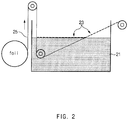
- FIGS. 1 to 3 are cross-sectional views of processes for explaining a method of manufacturing an electrode current collector, according to an embodiment of the present invention.
- a CNT dispersion is prepared by dispersing CNTs in a dispersion solvent (process 1).
- the dispersion solvent is not particularly limited as long as it can effectively disperse CNTs and is readily soluble in water.
- the dispersion solvent may be one selected from the group consisting of distilled water, alcohols such as ethanol and the like, acetonitrile, and acetone, or a mixture of two or more of these solvents may also be used.
- the CNTs are a highly crystalline carbon-based material in which hexagonally arranged carbon atoms take a tube form, and have very high electrical conductivity and lithium ion conductivity, and thus may provide a path for reacting with lithium ions in an electrode. Accordingly, uniform current and voltage distribution may be maintained in the electrode during cycles of charging and discharging, resulting in significant improvement of cycle characteristics.
- the CNTs have excellent tensile strength, i.e., approximately 100 times or more greater than that of steel due to strong covalent bonds of carbon atoms, exhibit non-conductive, conductive or semiconducting properties according to unique chirality, and have high resistance to fracturing, and thus may prevent the current collector from being deformed by repetition of charging/discharging or external force and prevent the surface of the current collector from being oxidized in an abnormal battery environment such as high temperature, overcharging, or the like, whereby battery safety may be significantly enhanced.
- the CNTs may include multi-walled CNTs (MWCNTs) formed as three or more layers and having a diameter of about 5 nm to about 100 nm.
- MWCNTs multi-walled CNTs
- the CNTs may further optionally include, in addition to the MWCNTs, single-walled CNTs (SWCNTs) formed as a single layer and having a diameter of about 1 nm, or double-walled CNTs (DWCNTs) formed as double layers and having a diameter of about 1.4 nm to about 3 nm.
- SWCNTs single-walled CNTs
- DWCNTs double-walled CNTs
- the CNTs of the present invention may further include bundle type CNTs in which a plurality of CNTs are arranged in parallel or intertwine with each other, or non-bundle type or entangled type CNTs in which CNTs agglomerate with each other in an irregular form.
- the bundle type CNTs may basically have a shape in which a plurality of CNT strands are grouped together to form a bundle, and these strands have a linear shape, a curved shape, or a mixed shape thereof.
- the bundle type CNTs may also have a linear shape, a curved shape, or a mixed shape thereof.
- such bundle type CNTs may have a thickness of 50 nm to 100 nm.
- the CNT dispersion is prepared by dispersing 0.1 wt% to 10 wt% of CNTs in the dispersion solvent. At this time, when the amount of the CNTs is less than 0.1 wt%, the CNT film is not uniformly formed on the water surface, and, when the amount of the CNTs is greater than 10 wt%, the CNT film formed on the water surface agglomerates, resulting in reduced yield.
- water 21 having high surface tension is added to a water bath, and then a CNT dispersion is sprayed onto the water 21.
- the dispersion solvent is completely dissolved in the water 21, and, consequently, a CNT film 23 may be formed on a surface of the water 21.
- a spraying rate of the dispersion may appropriately vary according to concentration, and may range from about 1 L/min to about 100 L/min.
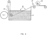
- metal foil 25 is transferred in a roll-to-roll manner after being unwound while passing through the water 21 at an angle such that one surface of the metal foil 25 is brought into contact with one end of the CNT film 23 formed on the water surface, thereby forming a CNT coating layer on the metal foil 25 (process 3).
- the metal foil 25 is transferred at a rate of 10 m/min to 50 m/min, which is within a range of an operating speed of a coater, and a transfer angle of the metal foil 25 with respect to the water surface ranges from 20° to 45°.
- the transfer angle is 45° or less, the CNT film formed on the water surface may be effectively adsorbed onto the metal foil.
- the metal foil is a part in which migration of electrons occurs via an electrochemical reaction of an active material, and is not particularly limited as long as it does not cause any chemical change and has conductivity to be used as an electrode current collector.
- the metal foil may be made of copper, stainless steel, aluminum, nickel, titanium, or calcined carbon; stainless steel surface-treated with carbon, nickel, titanium, or silver; an aluminum-cadmium alloy; or the like.
- the metal foil may typically have a thickness of 3 ⁇ m to 500 ⁇ m.
- the metal foil may be in any of various forms including a film, a sheet, a net, a porous structure, a foam, non-woven fabric, and the like.
- a CNT layer having a uniform thickness may be formed on the metal foil 25.
- the CNT film floating on the water surface by surface tension is adsorbed onto an upper end of the metal foil positioned below the CNT film by the Van der Waals attraction acting between the CNTs and the metal current collector, thereby forming a thin CNT coating layer.
- the CNT coating layer may have a thickness of 10 nm to 5 ⁇ m.
- the thickness of the CNT coating layer is too small, i.e., less than 10 nm, it is difficult to improve electrical conductivity and obtain a rate characteristics improvement effect according thereto.
- the thickness of the CNT coating layer is greater than 5 ⁇ m, it results in a reduction in the absolute amount of an electrode active material relative to a standard, and thus battery capacity may be decreased.
- the metal foil 25 with the CNT coating layer formed thereon is subjected to heat treatment 27 while being rewound, thereby curing the CNT coating layer (process 4).
- the curing process may be performed by applying hot air at a temperature of 70 °C to 130 °C for a residence time of 10 seconds to 1 minute.
- the CNT coating layer may be insufficiently dried, and, when the hot air temperature is greater than 130 °C, the CNT coating layer may be oxidized.
- a path for transfer of electrons in an electrode is mainly formed by a conductive material
- a conductive material is mainly distributed in the vicinity of an active material, and thus it is difficult for the transfer of electrons to smoothly occur.
- a method of surface-treating a current collector has been proposed, but this method involves complicated processes and manufacturing costs increase.
- a CNT coating layer is formed on a surface of an electrode current collector by only a simple coating process without a separate mechanical device or an additional process, thereby securing a conductive path for a conductive material distributed in the vicinity of an active material.
- the time spent for forming the coating layer on a surface of the current collector is merely several minutes, and, as described above, desired effects may be sufficiently achieved even by a small coating area, and thus the coating layer may be formed by rapid and continuous processes.
- the CNT coating process does not include etching or the like, damage to the surface of the current collector or deterioration of the strength of the current collector may be prevented.
- the CNT coating layer is first formed on the surface of the electrode current collector before forming an electrode mixture layer, and, accordingly, a specific surface area between the active material and the current collector may be increased and electronic conductivity therebetween may be significantly increased.
- a specific surface area between the active material and the current collector may be increased and electronic conductivity therebetween may be significantly increased.
- CNTs in the form of a long, linear conductive material may form an excellent conductive path, the dispersion thereof in an electrode slurry is difficult.
- the CNT coating layer is previously formed on the current collector, and, accordingly, this structure may be more easily applied to an electrode, and it is predicted that the amount of a conductive material in the electrode slurry may be decreased.
- the method of manufacturing an electrode current collector may further include forming an electrode mixture layer by applying an electrode slurry on the CNT coating layer using a coater 29 for forming an active material while transferring the metal foil 25 with the CNT coating layer formed thereon, and then pressing and drying the resulting structure.
- the electrode slurry may include a negative electrode slurry.
- An embodiment of the present disclosure also provides an electrode for a secondary battery, including an electrode current collector manufactured using the above-described manufacturing method of the present invention.
- the electrode for a secondary battery is manufactured according to the manufacturing method of the present invention, and includes: an electrode current collector with a CNT coating layer formed on a surface thereof; and an electrode mixture layer formed on a surface of the CNT coating layer.
- the CNT coating layer may include MWCNTs, and the CNT coating layer may have a thickness of 10 nm to 5 ⁇ m, preferably, 30 nm to 3 ⁇ m.
- the electrode for a secondary battery may be a negative electrode, but the present invention is not limited thereto.
- the electrode mixture layer may be formed via application of a negative electrode slurry including a negative electrode active material, a conductive material, and, optionally, at least one additive selected from the group consisting of a binder and a filler.
- the negative electrode active material may be a carbonaceous material.
- the carbonaceous material may be one selected from the group consisting of graphite, graphitizable carbon (soft carbon), non-graphitizable carbon (hard carbon), carbon black, graphene, and graphene oxides, or a mixture of two or more of these materials.
- the graphite may include natural graphite or artificial graphite, e.g., mesophase carbon microbeads (MCMBs), mesophase pitch-based carbon fiber (MPCF), or the like.
- the conductive material is not particularly limited so long as it does not cause chemical changes in the fabricated battery and has conductivity.
- conductive materials include graphite such as natural or artificial graphite; carbonaceous materials such as carbon black, acetylene black, Ketjen black, channel black, furnace black, lamp black, and thermal black; conductive fibers such as carbon fibers and metallic fibers; metallic powders such as carbon fluoride powder, aluminum powder, and nickel powder; conductive whiskers such as zinc oxide and potassium titanate; conductive metal oxides such as titanium oxide; and polyphenylene derivatives.
- the conductive material may generally be included in an amount of 1 wt% to 30 wt% based on the total weight of a slurry.
- the binder is not particularly limited as long as it assists in binding of an active material to a conductive material or the like and binding of an active material to a current collector.
- Non-limiting examples of the binder include polyvinylidenefluoride, polyvinyl alcohol, carboxymethylcellulose (CMC), starch, hydroxypropylcellulose, regenerated cellulose, polyvinylpyrrolidone, tetrafluoroethylene, polyethylene, polypropylene, ethylene-propylene-diene monomers (EPDMs), sulfonated EPDMs, styrene-butadiene rubber, fluorine rubber, and various copolymers.
- the binder may be generally included in an amount of 1 wt% to 30 wt% based on the total weight of a slurry.
- the filler is a component that suppresses the expansion of an electrode and may be optionally used, and is not particularly limited as long as it is a fibrous material that does not cause any chemical change in the fabricated battery.
- the filler may be an olefin-based polymer such as polyethylene, polypropylene, or the like; a fibrous material such as glass fiber, carbon fiber, or the like.
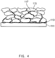
- FIG. 4 illustrates a cross-section of an electrode including an electrode current collector with a CNT coating layer formed thereon, manufactured according to the method of the present invention
- FIG. 5 is a cross-sectional view of a general electrode.
- the electrode for a secondary battery of the present invention has a structure in which a CNT coating layer 113 is formed on a surface of an electrode current collector 111, and an electrode mixture layer including an electrode active material 115 and a conductive material 117 is formed on the CNT coating layer 113.
- the CNT coating layer is uniformly formed on the electrode current collector, and thus forms very stable binding such as direct chemical binding or the like with the electrode active material and the conductive material included in the electrode mixture layer.
- the electrode of the present invention may significantly increase adhesion between an electrode mixture and a current collector due to the CNT coating layer formed on the current collector, and thus peeling of an electrode active material, an increase in internal resistance of a battery, and deterioration of battery characteristics may be prevented.
- a binder and a conductive material included in the electrode mixture may be added in a minimum amount, and thus electrical conductivity may be enhanced, resulting in significant improvement of output characteristics of a secondary battery.
- the present disclosure also provides a secondary battery including the electrode as a positive electrode and/or a negative electrode.
- the secondary battery is preferably a lithium secondary battery.
- the lithium secondary battery has a structure in which an electrode assembly consisting of a positive electrode, a negative electrode, and a separator therebetween is impregnated with a lithium salt-containing non-aqueous electrolyte.
- the positive electrode may be manufactured by coating a positive electrode current collector with a positive electrode slurry including a positive electrode active material, a conductive material, and, optionally, at least one additive selected from the group consisting of a binder and a filler.
- the positive electrode active material may be a known positive electrode active material for a secondary battery.
- the conductive material, the binder, and the filler may be identical to or different from those used in the negative electrode active material.
- the separator is disposed between the positive electrode and the negative electrode, and may be an insulating thin film having high ion permeability and high mechanical strength.
- the separator may generally have a pore diameter of 0.01 ⁇ m to 10 ⁇ m, and may generally have a thickness of 5 ⁇ m to 300 ⁇ m.
- separator for example, sheets or non-woven fabrics, made of an olefin-based polymer such as polypropylene; or glass fiber or polyethylene, which have chemical resistance and hydrophobicity, or Kraft paper is used.
- separators include the Celgard series such as Celgard TM 2400 and 2300 (available from Hoechest Celanese Corp.), polypropylene separators (available from Ube Industries Ltd., or Pall RAI Co.), and the polyethylene series (available from Tonen or Entek).
- a gel polymer electrolyte may be coated on the separator to enhance battery stability.
- examples of gel polymers include, but are not limited to, polyethylene oxide, polyvinylidenefluoride, and polyacrylonitrile.
- the solid electrolyte may also serve as a separator.
- the lithium salt-containing non-aqueous electrolyte includes a non-aqueous electrolyte and a lithium salt.
- a non-aqueous electrolyte solution As the non-aqueous electrolyte, a non-aqueous electrolyte solution, an organic solid electrolyte, an inorganic solid electrolyte, or the like is used.
- the non-aqueous electrolyte solution may be, for example, an aprotic organic solvent such as N-methyl-2-pyrrolidinone, propylene carbonate, ethylene carbonate, butylene carbonate, dimethyl carbonate, diethyl carbonate, ethyl methyl carbonate, ⁇ -butyrolactone, 1,2-dimethoxy ethane, 1,2-diethoxy ethane, 2-methyl tetrahydrofuran, dimethylsulfoxide, 1,3-dioxolane, 4-methyl-1,3-dioxene, diethylether, formamide, dimethylformamide, dioxolane, acetonitrile, nitromethane, methyl formate, methyl acetate, phosphoric acid triester, trimethoxy methane, dioxolane derivatives, sulfolane, methyl sulfolane, 1,3-dimethyl-2-imidazolidinone, propylene carbonate derivatives,
- Non-limiting examples of the organic solid electrolyte include polyethylene derivatives, polyethylene oxide derivatives, polypropylene oxide derivatives, phosphoric acid ester polymers, poly agitation lysine, polyester sulfide, polyvinyl alcohol, polyvinylidene fluoride, and polymers containing ionic dissociation groups.
- the lithium salt is a material that is readily soluble in the non-aqueous electrolyte.
- Non-limiting examples of the lithium salt include LiCl, LiBr, Lil, LiClO 4 , LiBF 4 , LiB 10 C 10 , LiPF 6 , LiCF 3 SO 3 , LiCF 3 CO 2 , LiAsF 6 , LiSbF 6 , LiAlCl 4 , CH 3 SO 3 U, CF 3 SO 3 Li, (CF 3 SO 2 ) 2 NLi, chloroborane lithium, lower aliphatic carboxylic acid lithium, lithium tetraphenyl borate, and imides.
- pyridine triethylphosphite, triethanolamine, cyclic ethers, ethylenediamine, n-glyme, hexaphosphoric triamide, nitrobenzene derivatives, sulfur, quinone imine dyes, N-substituted oxazolidinone, N,N-substituted imidazolidine, ethylene glycol dialkyl ethers, ammonium salts, pyrrole, 2-methoxy ethanol, aluminum trichloride, or the like may be added to the electrolyte.
- the electrolyte may further include a halogen-containing solvent such as carbon tetrachloride and ethylene trifluoride.
- the electrolyte may further include carbon dioxide gas.
- CNTs 5 g were dispersed in 100 g of isopropyl as a solvent to prepare a CNT dispersion, and then the CNT dispersion was sprayed onto distilled water to form a CNT film on a water surface.
- Cu foil having a thickness of 10 ⁇ m was transferred at a rate of 30 m/min in a roll-to-roll manner after being unwound while passing through the water at an angle of 30° such that one surface of the Cu foil was brought into contact with one end of the CNT film formed on the water surface, forming a CNT coating layer having a thickness of about 50 nm on a surface of the Cu foil.
- the Cu foil with the CNT coating layer formed thereon was heat treated by hot air at 120 °C for 20 seconds while being rewound to cure the CNT coating layer, thereby completing the manufacture of a negative electrode current collector with the CNT coating layer formed thereon (see FIG. 4 ).
- the negative electrode active material slurry was applied on the negative electrode current collector manufactured using the above-described processes with a thickness of 65 ⁇ m, followed by roll pressing, thereby completing the manufacture of a negative electrode.
- LiNi 0.33 Mn 0.33 Co 0.33 O 2 as a positive electrode active material, acetylene black as a conductive material, and SBR as a binder were mixed in a weight ratio of 94:3.5:2.5, and then the resulting mixture was added to NMP to prepare a positive electrode active material slurry.
- the prepared slurry was applied on one surface of aluminum (Al) foil, followed by roll pressing, thereby completing the manufacture of a positive electrode.
- a polyolefin separator was disposed between the positive electrode and the negative electrode, and then an electrolyte prepared by dissolving 1M LiPF 6 in a mixed solvent of ethylene carbonate (EC) and diethyl carbonate (DEC) in a volume ratio of 30:70 was injected into the resulting structure, thereby completing the manufacture of a lithium secondary battery.
- EC ethylene carbonate
- DEC diethyl carbonate
- CNTs 10 g were dispersed in 100 g of isopropyl as a solvent to prepare a CNT dispersion, and then the CNT dispersion was sprayed onto distilled water to form a CNT film on a water surface.
- Cu foil having a thickness of 10 ⁇ m was transferred at a rate of 50 m/min in a roll-to-roll manner after being unwound while passing through the water at an angle of 30° such that one surface of the Cu foil was brought into contact with one end of the CNT film formed on the water surface, forming a CNT coating layer having a thickness of about 50 nm on a surface of the Cu foil.
- the Cu foil with the CNT coating layer formed thereon was heat treated by hot air at 120 ⁇ for 20 seconds while being rewound to cure the CNT coating layer, thereby completing the manufacture of a negative electrode current collector with the CNT coating layer formed thereon (see FIG. 4 ).
- a negative electrode and a lithium secondary battery including the same were manufactured in the same manner as in Example 1, except that the negative electrode current collector manufactured according to the above-described processes was used.
- a negative electrode and a lithium secondary battery including the same were manufactured in the same manner as in Example 1, except that Cu foil not including the CNT coating layer formed thereon was used instead of the negative electrode current collector manufactured according to Example 1.
- a negative electrode and a lithium secondary battery including the same were manufactured in the same manner as in Example 1, except that the negative electrode current collector manufactured according to the above-described processes was used instead of the negative electrode current collector of Example 1.
- the measurement of resistance according to component was performed by electrochemical impedance spectroscopy (EIS) in which resistance according to component of a secondary battery is separated via measurement of impedance by applying minute alternating current signals with different frequencies to the cell.
- EIS electrochemical impedance spectroscopy
- the EIS experiment is susceptible to temperature, and thus was performed in a chamber at 25 °C, which is similar to room temperature, to reduce errors.
- the batteries of Examples 1 and 2 exhibited a lower charge transfer resistance than that of the batteries of Comparative Examples 1 and 2, and exhibited similar diffusion resistance. This is determined due to the fact that electronic conductivity is improved due to formation of the CNT coating layer on the negative electrode foil, resulting in enhanced charge transfer resistance, and it can be confirmed that the diffusion resistances, which are a resistance associated with pores of an electrode, or the like, of the batteries of the present invention are similar to each other. A higher concentration of CNTs were used in Example 2 than in Example 1, and, accordingly, the charge transfer resistance is seen as being slightly increased in Example 2 compared to that in Example 1.
- Comparative Example 2 a negative electrode current collector manufactured by mixing CNTs and a polymer binder in a solvent and then coating the metal foil with the resulting mixture by dip coating was used, and thus the charge transfer resistance is seen as being slightly decreased compared to that in Comparative Example 1, but Comparative Example 2 still shows a higher resistance than that of Examples 1 and 2. This is because electrical conductivity of a polymer included as a binder is poor, and thus the polymer binder forms a thick film together with the CNTs and, as a result, serves as a non-conductor.
- each of the lithium secondary batteries of Examples 1 and 2, and Comparative Examples 1 and 2 having a battery capacity of 50 mAh was charged at a constant current of 0.33 C and 2.5 V until the voltage reached 4.25 V, and then charged at a constant voltage of 4.25 V, and the charging was cut off when the charge current reached 2.5 mA.
- each secondary battery was allowed to stand for 30 minutes, and then discharged at a constant current of 0.33 C until the voltage reached 2.5 V.
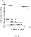
- This charging/discharging behavior is denoted as the 1 st cycle, and this cycle was repeated 100 times, and then capacity retention rates according to cycle of the lithium secondary batteries of Examples 1 and 2, and Comparative Examples 1 and 2 were measured, and the results thereof are shown in FIG. 6 .
- the lithium secondary batteries of Examples 1 and 2 exhibited a capacity retention rate of 90% or more while the cycle was repeated 100 times, while the lithium secondary batteries of Comparative Examples 1 and 2 exhibited a rapidly decreased capacity retention rate after the 40 th cycle and thus exhibited a capacity retention rate of about 80%.
- the CNT coating layer formed on the surface of the negative electrode current collector without physical damage maintains a conductive network between the CNT coating layer and an electrode during the cycle of charging and discharging of the lithium secondary battery, and thus an increase in resistance is suppressed. Accordingly, as in Examples 1 and 2, a lithium secondary battery including such a CNT coating layer exhibits excellent lifespan characteristics.
Landscapes
- Chemical & Material Sciences (AREA)
- Engineering & Computer Science (AREA)
- Electrochemistry (AREA)
- General Chemical & Material Sciences (AREA)
- Chemical Kinetics & Catalysis (AREA)
- Materials Engineering (AREA)
- Manufacturing & Machinery (AREA)
- Composite Materials (AREA)
- Nanotechnology (AREA)
- Organic Chemistry (AREA)
- Inorganic Chemistry (AREA)
- Battery Electrode And Active Subsutance (AREA)
- Cell Electrode Carriers And Collectors (AREA)
Priority Applications (1)
| Application Number | Priority Date | Filing Date | Title |
|---|---|---|---|
| PL17770534T PL3322010T3 (pl) | 2016-03-21 | 2017-03-15 | Sposób wytwarzania kolektora elektrody dla akumulatora |
Applications Claiming Priority (3)
| Application Number | Priority Date | Filing Date | Title |
|---|---|---|---|
| KR20160033535 | 2016-03-21 | ||
| KR1020170030761A KR101979678B1 (ko) | 2016-03-21 | 2017-03-10 | 이차전지용 전극 집전체의 제조 방법 및 상기 방법에 의해 제조된 전극 집전체를 포함하는 전극 |
| PCT/KR2017/002814 WO2017164563A2 (ko) | 2016-03-21 | 2017-03-15 | 이차전지용 전극 집전체의 제조 방법 및 상기 방법에 의해 제조된 전극 집전체를 포함하는 전극 |
Publications (3)
| Publication Number | Publication Date |
|---|---|
| EP3322010A2 EP3322010A2 (en) | 2018-05-16 |
| EP3322010A4 EP3322010A4 (en) | 2018-06-20 |
| EP3322010B1 true EP3322010B1 (en) | 2020-01-08 |
Family
ID=60035619
Family Applications (1)
| Application Number | Title | Priority Date | Filing Date |
|---|---|---|---|
| EP17770534.0A Active EP3322010B1 (en) | 2016-03-21 | 2017-03-15 | Method for manufacturing electrode collector for secondary battery |
Country Status (6)
| Country | Link |
|---|---|
| US (1) | US10483549B2 (pl) |
| EP (1) | EP3322010B1 (pl) |
| JP (1) | JP6758667B2 (pl) |
| KR (1) | KR101979678B1 (pl) |
| CN (1) | CN108780896B (pl) |
| PL (1) | PL3322010T3 (pl) |
Families Citing this family (7)
| Publication number | Priority date | Publication date | Assignee | Title |
|---|---|---|---|---|
| US11837709B2 (en) | 2019-12-09 | 2023-12-05 | Lg Energy Solution, Ltd. | Manufacturing apparatus of electrode for secondary battery comprising heating part and manufacturing method of electrode for secondary battery comprising heating process, for heating electrode current collector before coating with electrode active material slurry |
| CN116111097A (zh) * | 2023-04-11 | 2023-05-12 | 宁德新能源科技有限公司 | 用于电极片的导电涂层组合物、电极片、二次电池和电子设备 |
| KR20250144659A (ko) | 2024-03-27 | 2025-10-13 | 주식회사 리서스 | 도전재/고분자 혼합 조성물이 코팅된 전지 집전체 및 이의 제조방법 |
| KR20250147714A (ko) | 2024-03-27 | 2025-10-14 | 주식회사 리서스 | 도전재/고분자 조성물이 다층으로 코팅된 전지 집전체 및 이의 제조방법 |
| KR20250144581A (ko) | 2024-03-27 | 2025-10-13 | 주식회사 리서스 | 코어쉘 구조의 도전재/고분자 조성물이 코팅된 전지 집전체 및 이의 제조방법 |
| FR3165357A1 (fr) * | 2024-07-31 | 2026-02-06 | Saft | Revêtement pour collecteur de courant |
| CN119932655B (zh) * | 2025-04-08 | 2025-07-15 | 陕西优卡曼材料科技有限公司 | 适用于新一代ai及通信产业的电解铜箔及其制造方法 |
Family Cites Families (21)
| Publication number | Priority date | Publication date | Assignee | Title |
|---|---|---|---|---|
| JP3579714B2 (ja) * | 2001-01-29 | 2004-10-20 | 独立行政法人産業技術総合研究所 | カーボンナノチューブからなるlb膜 |
| WO2006035790A1 (ja) | 2004-09-30 | 2006-04-06 | Jsr Corporation | 共重合体および上層膜形成組成物 |
| JP2006176362A (ja) * | 2004-12-22 | 2006-07-06 | Fuji Xerox Co Ltd | カーボンナノチューブ薄膜の製造方法 |
| KR101400994B1 (ko) * | 2007-04-10 | 2014-05-29 | 한국과학기술원 | 고용량 리튬 이차전지용 전극 및 이를 함유하는 리튬이차전지 |
| KR101101153B1 (ko) | 2007-04-26 | 2012-01-05 | 주식회사 엘지화학 | 탄소나노튜브가 코팅된 이차전지용 집전체 및 이를포함하는 이차전지 |
| CN101315974B (zh) * | 2007-06-01 | 2010-05-26 | 清华大学 | 锂离子电池负极及其制备方法 |
| ES2379900T3 (es) * | 2007-09-14 | 2012-05-04 | Hong Fu Jin Precision Industry (Shenzhen) Co., (Shenzhen) Co., Ltd. | Batería de litio y método para fabricar un ánodo de la misma |
| CN101388447B (zh) * | 2007-09-14 | 2011-08-24 | 清华大学 | 锂离子电池负极及其制备方法 |
| JP2010061825A (ja) * | 2008-09-01 | 2010-03-18 | Toyota Motor Corp | 電池用集電箔及びその製造方法、並びに、電池 |
| US9257704B2 (en) * | 2009-07-06 | 2016-02-09 | Zeptor Corporation | Carbon nanotube composite structures and methods of manufacturing the same |
| US9331362B2 (en) * | 2009-12-21 | 2016-05-03 | Quallion Llc | Battery having electrode with carbon current collector |
| KR101405463B1 (ko) * | 2010-01-15 | 2014-06-27 | 그래핀스퀘어 주식회사 | 기체 및 수분 차단용 그래핀 보호막, 이의 형성 방법 및 그의 용도 |
| KR101147201B1 (ko) | 2010-02-08 | 2012-05-25 | 삼성에스디아이 주식회사 | 리튬이차전지의 음극, 이의 제조 방법 및 상기 음극전극을 포함하는 리튬 이차전지 |
| CN103187573B (zh) * | 2011-12-28 | 2016-01-20 | 清华大学 | 锂离子电池电极 |
| KR101327283B1 (ko) | 2012-03-20 | 2013-11-11 | 한국과학기술연구원 | 집전체 표면위에 형성된 고분자패턴을 이용하여 고성능 실리콘 전극제조 및 이를 포함하는 리튬계 이차전지음전극의 제조방법 |
| US20150093649A1 (en) | 2012-04-09 | 2015-04-02 | Showa Denko K.K. | Method of producing current collector for electrochemical element, method of producing electrode for electrochemical element, current collector for electrochemical element, electrochemical element, and coating liquid for fabricating current collector for electrochemical element |
| JP6169679B2 (ja) * | 2012-04-18 | 2017-07-26 | エルジー・ケム・リミテッド | 電極及びそれを含む二次電池 |
| KR101392932B1 (ko) * | 2012-04-25 | 2014-05-08 | 한국에너지기술연구원 | 고전기전도성 나노구조 탄소층 일체형 알루미늄 박 집전체 및 그 제조방법 |
| WO2014042080A1 (ja) * | 2012-09-14 | 2014-03-20 | 日産化学工業株式会社 | エネルギー貯蔵デバイス電極用複合集電体および電極 |
| RU2572840C2 (ru) | 2014-05-22 | 2016-01-20 | Мсд Текнолоджис Частная Компания С Ограниченной Ответственностью | Металлическая фольга с проводящим слоем и способ ее изготовления |
| WO2016004191A1 (en) * | 2014-07-02 | 2016-01-07 | General Nano Llc | Method for making a catalyst metal substrate for growth of carbon nanotubes |
-
2017
- 2017-03-10 KR KR1020170030761A patent/KR101979678B1/ko active Active
- 2017-03-15 EP EP17770534.0A patent/EP3322010B1/en active Active
- 2017-03-15 PL PL17770534T patent/PL3322010T3/pl unknown
- 2017-03-15 US US15/752,105 patent/US10483549B2/en active Active
- 2017-03-15 CN CN201780002914.3A patent/CN108780896B/zh active Active
- 2017-03-15 JP JP2018537605A patent/JP6758667B2/ja active Active
Non-Patent Citations (1)
| Title |
|---|
| None * |
Also Published As
| Publication number | Publication date |
|---|---|
| JP6758667B2 (ja) | 2020-09-23 |
| KR101979678B1 (ko) | 2019-05-17 |
| CN108780896A (zh) | 2018-11-09 |
| JP2018532246A (ja) | 2018-11-01 |
| CN108780896B (zh) | 2021-09-14 |
| EP3322010A4 (en) | 2018-06-20 |
| US20180241045A1 (en) | 2018-08-23 |
| US10483549B2 (en) | 2019-11-19 |
| KR20170109493A (ko) | 2017-09-29 |
| PL3322010T3 (pl) | 2020-05-18 |
| EP3322010A2 (en) | 2018-05-16 |
Similar Documents
| Publication | Publication Date | Title |
|---|---|---|
| US11891523B2 (en) | Composite negative electrode active material, method of manufacturing the same, and negative electrode including the same | |
| EP3322010B1 (en) | Method for manufacturing electrode collector for secondary battery | |
| US11901540B2 (en) | Composite anode active material, method of preparing the same, and lithium secondary battery including anode including composite anode active material | |
| US9373846B2 (en) | Negative electrode active material and method for producing the same | |
| KR101540618B1 (ko) | 이차전지용 전극 및 그것의 제조 방법 | |
| KR102207524B1 (ko) | 리튬 이차전지용 전극의 제조방법 및 이로부터 제조된 리튬 이차전지용 전극 | |
| KR102690258B1 (ko) | 요크-쉘(Yolk-shell) 구조의 Si 음극재를 제조하는 방법 | |
| KR102359813B1 (ko) | Cnt를 포함하는 프라이머 층이 코팅된 음극 및 이의 제조방법 | |
| CN104718657A (zh) | 锂二次电池 | |
| KR20250088696A (ko) | 황-탄소 복합체, 이의 제조방법, 이를 포함하는 리튬 이차전지용 양극 및 리튬 이차전지 | |
| KR101745416B1 (ko) | 리튬이차전지용 양극활물질 및 그 제조방법 | |
| KR102733688B1 (ko) | 리튬 이차전지용 양극 슬러리 조성물, 이를 포함하는 양극 및 리튬 이차전지 | |
| KR102359828B1 (ko) | 그래핀 및 cnt를 포함하는 프라이머 층이 코팅된 음극 및 이의 제조방법 | |
| KR101156614B1 (ko) | 고중합도 폴리아크릴로니트릴 바인더를 포함한 전극재료,그 제조방법 및 그 전극재료를 포함하는 리튬 이차전지 | |
| KR102840395B1 (ko) | 양극 슬러리 및 이를 이용한 리튬 이차전지용 양극 | |
| US12199270B2 (en) | Positive electrode active material for lithium rechargeable battery, manufacturing method therefor and lithium rechargeable battery comprising same | |
| KR20180036626A (ko) | 이차전지용 분리막 제조 방법 | |
| KR102147495B1 (ko) | 안전성이 향상된 양극 활물질 및 이를 포함하는 리튬이차전지 | |
| KR102798805B1 (ko) | 리튬 이차전지용 양극 및 이를 포함하는 리튬 이차전지 | |
| CN115803916B (zh) | 包含正极添加剂的锂二次电池 | |
| KR20090113086A (ko) | 리튬이차전지의 음극전극, 이의 제조방법, 및 상기 음극전극을 포함하는 리튬 이차전지 | |
| WO2017164563A2 (ko) | 이차전지용 전극 집전체의 제조 방법 및 상기 방법에 의해 제조된 전극 집전체를 포함하는 전극 | |
| KR102071503B1 (ko) | 유연성이 향상된 이차전지용 전극 합제 | |
| KR101572456B1 (ko) | 양극 활물질이 리튬 전이금속 폴리 음이온 화합물로 이루어지고, 음극 활물질이 결정질 탄소로 이루어진 리튬 이차전지 | |
| KR20220163855A (ko) | 리튬 이차전지용 양극 및 이를 포함하는 리튬 이차전지 |
Legal Events
| Date | Code | Title | Description |
|---|---|---|---|
| STAA | Information on the status of an ep patent application or granted ep patent |
Free format text: STATUS: THE INTERNATIONAL PUBLICATION HAS BEEN MADE |
|
| PUAI | Public reference made under article 153(3) epc to a published international application that has entered the european phase |
Free format text: ORIGINAL CODE: 0009012 |
|
| STAA | Information on the status of an ep patent application or granted ep patent |
Free format text: STATUS: REQUEST FOR EXAMINATION WAS MADE |
|
| 17P | Request for examination filed |
Effective date: 20180206 |
|
| AK | Designated contracting states |
Kind code of ref document: A2 Designated state(s): AL AT BE BG CH CY CZ DE DK EE ES FI FR GB GR HR HU IE IS IT LI LT LU LV MC MK MT NL NO PL PT RO RS SE SI SK SM TR |
|
| AX | Request for extension of the european patent |
Extension state: BA ME |
|
| A4 | Supplementary search report drawn up and despatched |
Effective date: 20180517 |
|
| RIC1 | Information provided on ipc code assigned before grant |
Ipc: H01M 4/75 20060101ALI20180511BHEP Ipc: H01M 4/04 20060101ALI20180511BHEP Ipc: H01M 4/66 20060101AFI20180511BHEP Ipc: H01M 4/13 20100101ALI20180511BHEP Ipc: H01M 10/0525 20100101ALI20180511BHEP |
|
| R17D | Deferred search report published (corrected) |
Effective date: 20180907 |
|
| STAA | Information on the status of an ep patent application or granted ep patent |
Free format text: STATUS: EXAMINATION IS IN PROGRESS |
|
| 17Q | First examination report despatched |
Effective date: 20190313 |
|
| REG | Reference to a national code |
Ref country code: DE Ref legal event code: R079 Ref document number: 602017010765 Country of ref document: DE Free format text: PREVIOUS MAIN CLASS: H01M0004660000 Ipc: B82Y0030000000 |
|
| DAV | Request for validation of the european patent (deleted) | ||
| DAX | Request for extension of the european patent (deleted) | ||
| RIC1 | Information provided on ipc code assigned before grant |
Ipc: H01M 4/04 20060101ALI20190708BHEP Ipc: H01M 4/66 20060101ALI20190708BHEP Ipc: H01M 10/0525 20100101ALI20190708BHEP Ipc: B82Y 40/00 20110101ALI20190708BHEP Ipc: H01M 4/13 20100101ALI20190708BHEP Ipc: H01M 4/02 20060101ALI20190708BHEP Ipc: C01B 32/174 20170101ALI20190708BHEP Ipc: B82Y 30/00 20110101AFI20190708BHEP Ipc: H01M 4/75 20060101ALI20190708BHEP |
|
| GRAP | Despatch of communication of intention to grant a patent |
Free format text: ORIGINAL CODE: EPIDOSNIGR1 |
|
| STAA | Information on the status of an ep patent application or granted ep patent |
Free format text: STATUS: GRANT OF PATENT IS INTENDED |
|
| INTG | Intention to grant announced |
Effective date: 20190926 |
|
| GRAS | Grant fee paid |
Free format text: ORIGINAL CODE: EPIDOSNIGR3 |
|
| GRAA | (expected) grant |
Free format text: ORIGINAL CODE: 0009210 |
|
| STAA | Information on the status of an ep patent application or granted ep patent |
Free format text: STATUS: THE PATENT HAS BEEN GRANTED |
|
| AK | Designated contracting states |
Kind code of ref document: B1 Designated state(s): AL AT BE BG CH CY CZ DE DK EE ES FI FR GB GR HR HU IE IS IT LI LT LU LV MC MK MT NL NO PL PT RO RS SE SI SK SM TR |
|
| REG | Reference to a national code |
Ref country code: GB Ref legal event code: FG4D |
|
| REG | Reference to a national code |
Ref country code: CH Ref legal event code: EP |
|
| REG | Reference to a national code |
Ref country code: DE Ref legal event code: R096 Ref document number: 602017010765 Country of ref document: DE |
|
| REG | Reference to a national code |
Ref country code: IE Ref legal event code: FG4D |
|
| REG | Reference to a national code |
Ref country code: AT Ref legal event code: REF Ref document number: 1222472 Country of ref document: AT Kind code of ref document: T Effective date: 20200215 |
|
| REG | Reference to a national code |
Ref country code: NL Ref legal event code: MP Effective date: 20200108 |
|
| REG | Reference to a national code |
Ref country code: LT Ref legal event code: MG4D |
|
| PG25 | Lapsed in a contracting state [announced via postgrant information from national office to epo] |
Ref country code: PT Free format text: LAPSE BECAUSE OF FAILURE TO SUBMIT A TRANSLATION OF THE DESCRIPTION OR TO PAY THE FEE WITHIN THE PRESCRIBED TIME-LIMIT Effective date: 20200531 Ref country code: NO Free format text: LAPSE BECAUSE OF FAILURE TO SUBMIT A TRANSLATION OF THE DESCRIPTION OR TO PAY THE FEE WITHIN THE PRESCRIBED TIME-LIMIT Effective date: 20200408 Ref country code: FI Free format text: LAPSE BECAUSE OF FAILURE TO SUBMIT A TRANSLATION OF THE DESCRIPTION OR TO PAY THE FEE WITHIN THE PRESCRIBED TIME-LIMIT Effective date: 20200108 Ref country code: LT Free format text: LAPSE BECAUSE OF FAILURE TO SUBMIT A TRANSLATION OF THE DESCRIPTION OR TO PAY THE FEE WITHIN THE PRESCRIBED TIME-LIMIT Effective date: 20200108 Ref country code: RS Free format text: LAPSE BECAUSE OF FAILURE TO SUBMIT A TRANSLATION OF THE DESCRIPTION OR TO PAY THE FEE WITHIN THE PRESCRIBED TIME-LIMIT Effective date: 20200108 Ref country code: NL Free format text: LAPSE BECAUSE OF FAILURE TO SUBMIT A TRANSLATION OF THE DESCRIPTION OR TO PAY THE FEE WITHIN THE PRESCRIBED TIME-LIMIT Effective date: 20200108 |
|
| PG25 | Lapsed in a contracting state [announced via postgrant information from national office to epo] |
Ref country code: BG Free format text: LAPSE BECAUSE OF FAILURE TO SUBMIT A TRANSLATION OF THE DESCRIPTION OR TO PAY THE FEE WITHIN THE PRESCRIBED TIME-LIMIT Effective date: 20200408 Ref country code: GR Free format text: LAPSE BECAUSE OF FAILURE TO SUBMIT A TRANSLATION OF THE DESCRIPTION OR TO PAY THE FEE WITHIN THE PRESCRIBED TIME-LIMIT Effective date: 20200409 Ref country code: SE Free format text: LAPSE BECAUSE OF FAILURE TO SUBMIT A TRANSLATION OF THE DESCRIPTION OR TO PAY THE FEE WITHIN THE PRESCRIBED TIME-LIMIT Effective date: 20200108 Ref country code: IS Free format text: LAPSE BECAUSE OF FAILURE TO SUBMIT A TRANSLATION OF THE DESCRIPTION OR TO PAY THE FEE WITHIN THE PRESCRIBED TIME-LIMIT Effective date: 20200508 Ref country code: LV Free format text: LAPSE BECAUSE OF FAILURE TO SUBMIT A TRANSLATION OF THE DESCRIPTION OR TO PAY THE FEE WITHIN THE PRESCRIBED TIME-LIMIT Effective date: 20200108 Ref country code: HR Free format text: LAPSE BECAUSE OF FAILURE TO SUBMIT A TRANSLATION OF THE DESCRIPTION OR TO PAY THE FEE WITHIN THE PRESCRIBED TIME-LIMIT Effective date: 20200108 |
|
| REG | Reference to a national code |
Ref country code: DE Ref legal event code: R097 Ref document number: 602017010765 Country of ref document: DE |
|
| PG25 | Lapsed in a contracting state [announced via postgrant information from national office to epo] |
Ref country code: DK Free format text: LAPSE BECAUSE OF FAILURE TO SUBMIT A TRANSLATION OF THE DESCRIPTION OR TO PAY THE FEE WITHIN THE PRESCRIBED TIME-LIMIT Effective date: 20200108 Ref country code: ES Free format text: LAPSE BECAUSE OF FAILURE TO SUBMIT A TRANSLATION OF THE DESCRIPTION OR TO PAY THE FEE WITHIN THE PRESCRIBED TIME-LIMIT Effective date: 20200108 Ref country code: MC Free format text: LAPSE BECAUSE OF FAILURE TO SUBMIT A TRANSLATION OF THE DESCRIPTION OR TO PAY THE FEE WITHIN THE PRESCRIBED TIME-LIMIT Effective date: 20200108 Ref country code: CZ Free format text: LAPSE BECAUSE OF FAILURE TO SUBMIT A TRANSLATION OF THE DESCRIPTION OR TO PAY THE FEE WITHIN THE PRESCRIBED TIME-LIMIT Effective date: 20200108 Ref country code: SK Free format text: LAPSE BECAUSE OF FAILURE TO SUBMIT A TRANSLATION OF THE DESCRIPTION OR TO PAY THE FEE WITHIN THE PRESCRIBED TIME-LIMIT Effective date: 20200108 Ref country code: RO Free format text: LAPSE BECAUSE OF FAILURE TO SUBMIT A TRANSLATION OF THE DESCRIPTION OR TO PAY THE FEE WITHIN THE PRESCRIBED TIME-LIMIT Effective date: 20200108 Ref country code: SM Free format text: LAPSE BECAUSE OF FAILURE TO SUBMIT A TRANSLATION OF THE DESCRIPTION OR TO PAY THE FEE WITHIN THE PRESCRIBED TIME-LIMIT Effective date: 20200108 Ref country code: EE Free format text: LAPSE BECAUSE OF FAILURE TO SUBMIT A TRANSLATION OF THE DESCRIPTION OR TO PAY THE FEE WITHIN THE PRESCRIBED TIME-LIMIT Effective date: 20200108 |
|
| REG | Reference to a national code |
Ref country code: CH Ref legal event code: PL |
|
| PLBE | No opposition filed within time limit |
Free format text: ORIGINAL CODE: 0009261 |
|
| STAA | Information on the status of an ep patent application or granted ep patent |
Free format text: STATUS: NO OPPOSITION FILED WITHIN TIME LIMIT |
|
| REG | Reference to a national code |
Ref country code: AT Ref legal event code: MK05 Ref document number: 1222472 Country of ref document: AT Kind code of ref document: T Effective date: 20200108 |
|
| 26N | No opposition filed |
Effective date: 20201009 |
|
| REG | Reference to a national code |
Ref country code: BE Ref legal event code: MM Effective date: 20200331 |
|
| PG25 | Lapsed in a contracting state [announced via postgrant information from national office to epo] |
Ref country code: LU Free format text: LAPSE BECAUSE OF NON-PAYMENT OF DUE FEES Effective date: 20200315 |
|
| PG25 | Lapsed in a contracting state [announced via postgrant information from national office to epo] |
Ref country code: IE Free format text: LAPSE BECAUSE OF NON-PAYMENT OF DUE FEES Effective date: 20200315 Ref country code: IT Free format text: LAPSE BECAUSE OF FAILURE TO SUBMIT A TRANSLATION OF THE DESCRIPTION OR TO PAY THE FEE WITHIN THE PRESCRIBED TIME-LIMIT Effective date: 20200108 Ref country code: CH Free format text: LAPSE BECAUSE OF NON-PAYMENT OF DUE FEES Effective date: 20200331 Ref country code: AT Free format text: LAPSE BECAUSE OF FAILURE TO SUBMIT A TRANSLATION OF THE DESCRIPTION OR TO PAY THE FEE WITHIN THE PRESCRIBED TIME-LIMIT Effective date: 20200108 Ref country code: LI Free format text: LAPSE BECAUSE OF NON-PAYMENT OF DUE FEES Effective date: 20200331 |
|
| PG25 | Lapsed in a contracting state [announced via postgrant information from national office to epo] |
Ref country code: SI Free format text: LAPSE BECAUSE OF FAILURE TO SUBMIT A TRANSLATION OF THE DESCRIPTION OR TO PAY THE FEE WITHIN THE PRESCRIBED TIME-LIMIT Effective date: 20200108 Ref country code: BE Free format text: LAPSE BECAUSE OF NON-PAYMENT OF DUE FEES Effective date: 20200331 |
|
| PG25 | Lapsed in a contracting state [announced via postgrant information from national office to epo] |
Ref country code: TR Free format text: LAPSE BECAUSE OF FAILURE TO SUBMIT A TRANSLATION OF THE DESCRIPTION OR TO PAY THE FEE WITHIN THE PRESCRIBED TIME-LIMIT Effective date: 20200108 Ref country code: MT Free format text: LAPSE BECAUSE OF FAILURE TO SUBMIT A TRANSLATION OF THE DESCRIPTION OR TO PAY THE FEE WITHIN THE PRESCRIBED TIME-LIMIT Effective date: 20200108 Ref country code: CY Free format text: LAPSE BECAUSE OF FAILURE TO SUBMIT A TRANSLATION OF THE DESCRIPTION OR TO PAY THE FEE WITHIN THE PRESCRIBED TIME-LIMIT Effective date: 20200108 |
|
| PG25 | Lapsed in a contracting state [announced via postgrant information from national office to epo] |
Ref country code: MK Free format text: LAPSE BECAUSE OF FAILURE TO SUBMIT A TRANSLATION OF THE DESCRIPTION OR TO PAY THE FEE WITHIN THE PRESCRIBED TIME-LIMIT Effective date: 20200108 Ref country code: AL Free format text: LAPSE BECAUSE OF FAILURE TO SUBMIT A TRANSLATION OF THE DESCRIPTION OR TO PAY THE FEE WITHIN THE PRESCRIBED TIME-LIMIT Effective date: 20200108 |
|
| REG | Reference to a national code |
Ref country code: DE Ref legal event code: R081 Ref document number: 602017010765 Country of ref document: DE Owner name: LG ENERGY SOLUTION, LTD., KR Free format text: FORMER OWNER: LG CHEM, LTD., SEOUL, KR |
|
| P01 | Opt-out of the competence of the unified patent court (upc) registered |
Effective date: 20230408 |
|
| REG | Reference to a national code |
Ref country code: GB Ref legal event code: 732E Free format text: REGISTERED BETWEEN 20230824 AND 20230831 |
|
| PGFP | Annual fee paid to national office [announced via postgrant information from national office to epo] |
Ref country code: DE Payment date: 20250220 Year of fee payment: 9 |
|
| PGFP | Annual fee paid to national office [announced via postgrant information from national office to epo] |
Ref country code: FR Payment date: 20250221 Year of fee payment: 9 Ref country code: PL Payment date: 20250221 Year of fee payment: 9 |
|
| PGFP | Annual fee paid to national office [announced via postgrant information from national office to epo] |
Ref country code: GB Payment date: 20250224 Year of fee payment: 9 |