EP3321068A1 - Dispositif de fabrication additive d'objets tridimensionnels - Google Patents
Dispositif de fabrication additive d'objets tridimensionnels Download PDFInfo
- Publication number
- EP3321068A1 EP3321068A1 EP17178085.1A EP17178085A EP3321068A1 EP 3321068 A1 EP3321068 A1 EP 3321068A1 EP 17178085 A EP17178085 A EP 17178085A EP 3321068 A1 EP3321068 A1 EP 3321068A1
- Authority
- EP
- European Patent Office
- Prior art keywords
- exposure device
- process chamber
- frame construction
- exposure
- laser beam
- Prior art date
- Legal status (The legal status is an assumption and is not a legal conclusion. Google has not performed a legal analysis and makes no representation as to the accuracy of the status listed.)
- Granted
Links
- 239000000654 additive Substances 0.000 title claims abstract description 14
- 230000000996 additive effect Effects 0.000 title claims abstract description 14
- 238000004519 manufacturing process Methods 0.000 title claims abstract description 9
- 238000010276 construction Methods 0.000 claims abstract description 91
- 238000000034 method Methods 0.000 claims abstract description 88
- 239000004566 building material Substances 0.000 claims abstract description 28
- 238000007711 solidification Methods 0.000 claims abstract description 14
- 230000008023 solidification Effects 0.000 claims abstract description 14
- 239000000463 material Substances 0.000 claims description 9
- 238000002347 injection Methods 0.000 claims description 4
- 239000007924 injection Substances 0.000 claims description 4
- 239000002184 metal Substances 0.000 claims description 4
- 229910052751 metal Inorganic materials 0.000 claims description 4
- 238000000605 extraction Methods 0.000 claims description 2
- 239000011248 coating agent Substances 0.000 description 9
- 238000000576 coating method Methods 0.000 description 9
- 229910000831 Steel Inorganic materials 0.000 description 3
- 238000010438 heat treatment Methods 0.000 description 3
- 239000010959 steel Substances 0.000 description 3
- 229910001374 Invar Inorganic materials 0.000 description 2
- 229910001030 Iron–nickel alloy Inorganic materials 0.000 description 2
- 239000011521 glass Substances 0.000 description 2
- 238000002844 melting Methods 0.000 description 2
- 230000008018 melting Effects 0.000 description 2
- 230000003287 optical effect Effects 0.000 description 2
- 238000000110 selective laser sintering Methods 0.000 description 2
- 229910010293 ceramic material Inorganic materials 0.000 description 1
- 230000001419 dependent effect Effects 0.000 description 1
- 238000010586 diagram Methods 0.000 description 1
- 238000010309 melting process Methods 0.000 description 1
- 239000000843 powder Substances 0.000 description 1
- 239000012255 powdered metal Substances 0.000 description 1
- 230000005855 radiation Effects 0.000 description 1
Images

Classifications
-
- B—PERFORMING OPERATIONS; TRANSPORTING
- B22—CASTING; POWDER METALLURGY
- B22F—WORKING METALLIC POWDER; MANUFACTURE OF ARTICLES FROM METALLIC POWDER; MAKING METALLIC POWDER; APPARATUS OR DEVICES SPECIALLY ADAPTED FOR METALLIC POWDER
- B22F10/00—Additive manufacturing of workpieces or articles from metallic powder
-
- B—PERFORMING OPERATIONS; TRANSPORTING
- B29—WORKING OF PLASTICS; WORKING OF SUBSTANCES IN A PLASTIC STATE IN GENERAL
- B29C—SHAPING OR JOINING OF PLASTICS; SHAPING OF MATERIAL IN A PLASTIC STATE, NOT OTHERWISE PROVIDED FOR; AFTER-TREATMENT OF THE SHAPED PRODUCTS, e.g. REPAIRING
- B29C64/00—Additive manufacturing, i.e. manufacturing of three-dimensional [3D] objects by additive deposition, additive agglomeration or additive layering, e.g. by 3D printing, stereolithography or selective laser sintering
- B29C64/20—Apparatus for additive manufacturing; Details thereof or accessories therefor
- B29C64/264—Arrangements for irradiation
-
- B—PERFORMING OPERATIONS; TRANSPORTING
- B22—CASTING; POWDER METALLURGY
- B22F—WORKING METALLIC POWDER; MANUFACTURE OF ARTICLES FROM METALLIC POWDER; MAKING METALLIC POWDER; APPARATUS OR DEVICES SPECIALLY ADAPTED FOR METALLIC POWDER
- B22F12/00—Apparatus or devices specially adapted for additive manufacturing; Auxiliary means for additive manufacturing; Combinations of additive manufacturing apparatus or devices with other processing apparatus or devices
- B22F12/38—Housings, e.g. machine housings
-
- B—PERFORMING OPERATIONS; TRANSPORTING
- B22—CASTING; POWDER METALLURGY
- B22F—WORKING METALLIC POWDER; MANUFACTURE OF ARTICLES FROM METALLIC POWDER; MAKING METALLIC POWDER; APPARATUS OR DEVICES SPECIALLY ADAPTED FOR METALLIC POWDER
- B22F3/00—Manufacture of workpieces or articles from metallic powder characterised by the manner of compacting or sintering; Apparatus specially adapted therefor ; Presses and furnaces
- B22F3/003—Apparatus, e.g. furnaces
-
- B—PERFORMING OPERATIONS; TRANSPORTING
- B29—WORKING OF PLASTICS; WORKING OF SUBSTANCES IN A PLASTIC STATE IN GENERAL
- B29C—SHAPING OR JOINING OF PLASTICS; SHAPING OF MATERIAL IN A PLASTIC STATE, NOT OTHERWISE PROVIDED FOR; AFTER-TREATMENT OF THE SHAPED PRODUCTS, e.g. REPAIRING
- B29C64/00—Additive manufacturing, i.e. manufacturing of three-dimensional [3D] objects by additive deposition, additive agglomeration or additive layering, e.g. by 3D printing, stereolithography or selective laser sintering
- B29C64/20—Apparatus for additive manufacturing; Details thereof or accessories therefor
- B29C64/25—Housings, e.g. machine housings
-
- B—PERFORMING OPERATIONS; TRANSPORTING
- B33—ADDITIVE MANUFACTURING TECHNOLOGY
- B33Y—ADDITIVE MANUFACTURING, i.e. MANUFACTURING OF THREE-DIMENSIONAL [3-D] OBJECTS BY ADDITIVE DEPOSITION, ADDITIVE AGGLOMERATION OR ADDITIVE LAYERING, e.g. BY 3-D PRINTING, STEREOLITHOGRAPHY OR SELECTIVE LASER SINTERING
- B33Y10/00—Processes of additive manufacturing
-
- B—PERFORMING OPERATIONS; TRANSPORTING
- B33—ADDITIVE MANUFACTURING TECHNOLOGY
- B33Y—ADDITIVE MANUFACTURING, i.e. MANUFACTURING OF THREE-DIMENSIONAL [3-D] OBJECTS BY ADDITIVE DEPOSITION, ADDITIVE AGGLOMERATION OR ADDITIVE LAYERING, e.g. BY 3-D PRINTING, STEREOLITHOGRAPHY OR SELECTIVE LASER SINTERING
- B33Y30/00—Apparatus for additive manufacturing; Details thereof or accessories therefor
-
- B—PERFORMING OPERATIONS; TRANSPORTING
- B22—CASTING; POWDER METALLURGY
- B22F—WORKING METALLIC POWDER; MANUFACTURE OF ARTICLES FROM METALLIC POWDER; MAKING METALLIC POWDER; APPARATUS OR DEVICES SPECIALLY ADAPTED FOR METALLIC POWDER
- B22F10/00—Additive manufacturing of workpieces or articles from metallic powder
- B22F10/20—Direct sintering or melting
- B22F10/28—Powder bed fusion, e.g. selective laser melting [SLM] or electron beam melting [EBM]
-
- B—PERFORMING OPERATIONS; TRANSPORTING
- B22—CASTING; POWDER METALLURGY
- B22F—WORKING METALLIC POWDER; MANUFACTURE OF ARTICLES FROM METALLIC POWDER; MAKING METALLIC POWDER; APPARATUS OR DEVICES SPECIALLY ADAPTED FOR METALLIC POWDER
- B22F12/00—Apparatus or devices specially adapted for additive manufacturing; Auxiliary means for additive manufacturing; Combinations of additive manufacturing apparatus or devices with other processing apparatus or devices
- B22F12/40—Radiation means
- B22F12/49—Scanners
-
- Y—GENERAL TAGGING OF NEW TECHNOLOGICAL DEVELOPMENTS; GENERAL TAGGING OF CROSS-SECTIONAL TECHNOLOGIES SPANNING OVER SEVERAL SECTIONS OF THE IPC; TECHNICAL SUBJECTS COVERED BY FORMER USPC CROSS-REFERENCE ART COLLECTIONS [XRACs] AND DIGESTS
- Y02—TECHNOLOGIES OR APPLICATIONS FOR MITIGATION OR ADAPTATION AGAINST CLIMATE CHANGE
- Y02P—CLIMATE CHANGE MITIGATION TECHNOLOGIES IN THE PRODUCTION OR PROCESSING OF GOODS
- Y02P10/00—Technologies related to metal processing
- Y02P10/25—Process efficiency
Definitions
- Apparatus for the additive production of three-dimensional objects by successive layerwise selective exposure and consequent successive layerwise selective solidification of building material layers from a building material solidifiable by means of a laser beam comprising a process chamber and an exposure device having the further features of the preamble of claim 1.
- Corresponding devices for the additive production of three-dimensional objects are, for. B. in the form of devices for performing selective laser sintering or selective laser melting, known per se.
- Corresponding devices comprise a process chamber in which the successive layer-wise selective exposure and the concomitant successive layer-wise selective solidification of respective building material layers takes place, and an exposure device which is set up to produce a laser beam for selective exposure and concomitant solidification of respective building material layers.
- the process heat generated during operation of corresponding devices causes a heating of the process chamber.
- the invention has for its object to provide a contrast improved device for the additive production of three-dimensional objects.
- the object is achieved by a device for the additive production of three-dimensional objects according to claim 1.
- the dependent Claims relate to possible embodiments of the device.
- the device (“device”) described herein is for the additive production of three-dimensional objects, i. H.
- the building material may in particular be a particulate or powdered metal, plastic and / or ceramic material.
- the selective solidification of respective selectively to be consolidated building material layers is based on object-related Bau schemes.
- Corresponding Bau stylist describe the geometric-constructive shape of the respective object to be produced additive and can, for example, "geslicte" CAD data of the object to be produced additive.
- the device may be used as an SLM device, i. H. as a device for performing selective laser melting (SLM) process, or as an SLS device, d. H. as a device for performing selective laser sintering method (SLS method) may be formed.
- SLM selective laser melting
- SLS method selective laser sintering method
- the device comprises the functional components typically required for carrying out additive construction processes. These include in particular a coating device and an exposure device.
- the coating device is designed to form building material layers to be solidified selectively (in the construction plane of the device).
- the coating device may comprise several components, i. H. z. B. a one, in particular blade-shaped, coating tool comprehensive coating element and a guide device for guiding the coating element along a defined path of movement.
- the exposure device is configured to generate a laser beam for selective exposure and concomitant solidification of respective building material layers (in the building plane of the device).
- the exposure device may also comprise a plurality of components, ie, for example, a beam generating device for generating a laser beam, a beam deflection device (scanner device) for deflecting a laser beam generated by the beam generating device onto a selectively exposed area of a building material layer to be selectively solidified various optical elements, such.
- a beam generating device for generating a laser beam
- a beam deflection device scanner device
- the exposure device may also be referred to or considered as optics of the device.
- the exposure device is arranged or formed on a housing construction formed by one or more, in particular profile-like or -shaped, frame construction elements, or comprising such a heat-decoupled distance from the process chamber.
- a heat decoupled spaced arrangement or configuration of the exposure device i. H.
- one of the exposure device associated with the beam deflection device, relative to the process chamber is to be understood that no heat (thermal energy), which may lead to an undesirable change in the positioning, d. H. the orientation and / or arrangement that could lead to exposure device can be transferred from the process chamber to the exposure device.
- the exposure device is spatially spaced from the process chamber such that no heat transfer from the process chamber to the exposure device is possible.
- the exposure device is completely decoupled from the process chamber in thermal terms; a heat transfer from the process chamber to the exposure device (and vice versa) is not possible.
- a gap space defining a distance between the exposure device and the process chamber is typically formed between the exposure device and the process chamber.
- the gap space may define a distance between the exposure device and the process chamber of a few millimeters, ie in particular a distance of at least one millimeter. Accordingly, there is typically no physical, ie in particular no mechanical, contact between the exposure device and the process chamber, which could enable a transfer of heat from the process chamber to the exposure device.
- the exposure device is arranged on a frame construction.
- the rack construction may be an outer casing rack construction of the apparatus, which typically forms a (closed) casing construction of the apparatus and thus defines (substantially) the outer shape of the apparatus.
- the frame construction on which the exposure device is arranged or formed is not the outer housing support structure of the device.
- the device may, for. B. comprise a (common) frame construction, on which the exposure device and the process chamber are arranged or formed.
- the exposure device is arranged or formed at such a distance from the process chamber on the frame construction that a change in the positioning of the exposure device to the frame construction due to the introduced during operation of the device via the process chamber in the frame structure thermal energy is not or is not possible.
- the thermal energy introduced into the frame construction during operation of the device via the process chamber is simply not sufficient, in particular due to thermal expansion, to cause an undesired change in the positioning of the exposure device.
- the apparatus may comprise a plurality of separate frame structures arranged at a distance from each other in a thermally decoupled manner, wherein the exposure device is arranged or formed on a first frame construction and the process chamber on a second frame construction.
- a heat-decoupled arrangement of respective frame constructions means that no heat (thermal energy), which may lead to an undesired change in the positioning, ie. H. the alignment and / or arrangement that could lead to exposure device can be transferred from the second frame construction to the first frame construction.
- the respective frame structures are spatially spaced apart such that no heat transfer from the second frame construction to the first frame construction is possible.
- the respective frame structures can be arranged one inside the other, with the second frame construction having structurally smaller dimensions than the first frame construction.
- the second frame construction can be regarded as inner frame construction, the first frame construction as outer frame construction. This enables a compact, yet heat-decoupled arrangement of respective frame structures.
- the interior defined by the first or the outer frame construction can optionally be rendered inert.
- the exposure device can be formed on a separate frame construction section or on a separate frame construction element, which is formed from a material, in particular a metal, with a thermal expansion coefficient in a range between 0.5 and 3.0 ⁇ 10 -6 K -1 , arranged or formed.
- a material in particular a metal
- it may, for. B. is a known under the name "Invar" iron-nickel alloy whose coefficient of thermal expansion (in a temperature range between 20 and 90 ° C) is between 0.5 and 2.0 x 10 -6 K -1 .
- the frame construction on which the exposure device is arranged or formed is expediently formed from a material having a comparatively small thermal expansion coefficient (coefficient of linear expansion or spatial expansion coefficient).
- a gap space defining a distance between the exposure device and the process chamber is typically formed between the exposure device and the process chamber.
- the exposure device in particular a laser beam extraction point of the exposure device or one of these associated beam deflecting device, via which a laser beam from the exposure device, in particular one of the exposure device associated beam deflector, outputs and a Laserstrahleinkopplungstician, in particular a Laserstrahleinkopplungsful, via which a laser beam couples into or enters a process chamber interior defined by the process chamber, arranged or formed shielding element for shielding the laser beam extending between the exposure device, in particular the laser beam exit point of the exposure device, and the process chamber, in particular the laser beam injection point of the process chamber
- the shielding element may have a bellows-like or a sleeve-like or -shaped geometric-constructive shape and is formed from a suitable shielding material, ie, for example, glass, steel, etc. The shielding element ensures a shielding
- a shield housing construction comprising at least one, in particular planar, shielding element, which is arranged or formed around the frame construction on which the exposure device is arranged or formed, is arranged.
- the shielding housing construction constitutes an enclosure of at least the frame construction on which the exposure device is arranged or formed, which prevents an undesired exit of the laser beam, in particular via the gap space extending between the exposure device and the process chamber, from the device.
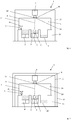
- the Fig. 1-3 each show a schematic diagram of a device 1 according to an embodiment of the device. 1
- the device 1 is used for the additive production of three-dimensional objects 2, ie in particular technical components or technical component groups, by successively layered selective exposure and associated successive layer-wise selective solidification of building material layers of a solidifiable building material 3, ie, for example, a metal powder, by means of laser radiation, cf. , Laser beam 4.
- the selective solidification of respective building material layers to be consolidated takes place on the basis of object-related building data.
- Corresponding Bau stylist describe the geometric or geometrical-constructive shape of each additive to be produced object 2 and may include, for example, "sliced" CAD data of the object to be manufactured 2.
- the device 1 can be designed as a laser CUSING® device, ie as a device for carrying out selective laser melting processes.
- the device 1 comprises the functional components required for carrying out additive construction processes; In the figures, only a coating device 5 and an exposure device 6 is shown.
- the coating device 5 is set up in a building plane of the device 1 for the purpose of forming building material layers to be selectively exposed or selectively solidified.
- the coating device 5 comprises a coater element assembly (not specified) comprising a plurality of coater elements, which device is movably mounted in a process chamber 7 of the device 1 via a guide device (not shown) in the horizontal direction as indicated by the double arrow P1.
- the exposure device 6 is adapted for the selective exposure of building material layers to be selectively solidified in the building plane of the device 1 and for this purpose comprises a beam generating device (not shown), which is set up to produce a laser beam 4, a beam deflection device (not shown), which is used to deflect one of the Beam generating device generated laser beam 4 is set up to be exposed area of a selectively to be solidified building material layer, and various optical elements such. As filter elements, lens elements, lens elements, etc.
- the exposure device 6 may also be referred to as the optics of the device 1 or considered.
- a dosing module 8 a building module 9 and an overflow module 10, which are docked to a lower region of the process chamber 7 of the device 1.
- the modules mentioned can also form a lower region of the process chamber 7.
- the exposure device 6 is connected to one by one or more, z. B. profile-like or -shaped, frame construction elements (unspecified) formed or such comprehensive housing construction 11 heat-coupled spaced from the process chamber 7.
- a heat decoupled spaced arrangement or design of the exposure device 6, that is, in particular of the exposure device 6 associated beam deflecting device, relative to the process chamber 7 is to be understood that no heat (thermal energy), which optionally to a undesired change in positioning, ie, the orientation and / or arrangement that could result in the exposure device 6 (eg, relative to a reference positioning), may be transferred from the process chamber 7 to the exposure device 6.
- the exposure device 6 is spatially spaced from the process chamber 7 such that no heat transfer from the process chamber 7 to the exposure device 6 is possible. The exposure device 6 is thus completely decoupled from the process chamber 7 in thermal terms.
- a gap space 12 defining a distance between the exposure device 6 and the process chamber 7 is formed between the exposure device 6 and the process chamber 7.
- the gap space 12 may be spaced a few millimeters, i. H. in particular define a distance of at least one millimeter. Between the exposure device 6 and the process chamber 7 therefore no physical, d. H. in particular, no mechanical, contact, which could allow heat transfer from the process chamber 7 to the exposure device 6.
- the exposure device 6 is arranged on a frame construction 11, which forms an outer housing frame construction of the device 1.
- the housing rack construction forms the (closed) housing or casing construction of the device 1 and thus defines (substantially) the external shape of the device 1.
- the process chamber 7 is also arranged on the frame construction 11.
- the device 1 therefore comprises a (common) frame construction 11, on which the exposure device 6 and the process chamber 7 are arranged.
- the exposure device 6 is arranged at such a distance from the process chamber 7 on the frame structure 11, that a change in the positioning of the exposure device 6 to the frame structure 11 due to the in operation the device 1 via the process chamber 7 in the frame structure 11 introduced thermal energy is not carried out or is not possible.
- the exposure device 6 is arranged at a distance from the process chamber 7 in such a way that the thermal energy introduced into the frame construction 11 during operation of the device 1 is insufficient, in particular due to thermal expansion, to cause an undesired change in the positioning of the exposure device 6.
- the exposure device 6 is arranged on a separate frame construction section (first frame construction section 11a) or on a separate frame construction element of the frame structure 11, which or of a material, in particular a metal, with a thermal expansion coefficient in one Range is formed between 0.5 and 3.0 ⁇ x 10 -6 K -1 .
- a corresponding material it may, for. B. is a known under the name "Invar" iron-nickel alloy whose coefficient of thermal expansion (in a temperature range between 20 and 90 ° C) is between 0.5 and 2.0 x 10 -6 K -1 .
- the shielding element 16 has a bellows-like or a sleeve-like geometric-constructive shape and is formed from a suitable shielding material, ie, for example, glass, steel, etc.
- the shielding element 16 ensures a shielding of the device 1, ie it prevents unwanted leakage of the laser beam 4, in particular via the gap space 12 extending between the exposure device and the process chamber, out of the device 1.
- the device 1 comprises a plurality of separate frame structures 11, 13 arranged at a distance from one another in a heat-insulated manner.
- the exposure device 6 is arranged on a first frame construction 11 and the process chamber 7 on a second frame construction 13.
- a heat-decoupled arrangement of respective frame structures 11, 13 should also be understood as meaning that no heat (thermal energy) which could possibly lead to an undesired change in the positioning of the exposure device 6 is transmitted from the second frame construction 13 to the first frame construction 11 can.
- the respective frame structures 11, 13 are spatially spaced apart such that no heat transfer from the second frame construction 13 to the first frame construction 11 is possible.
- the two frame structures 11, 13 are in the in Fig. 2 embodiment shown arranged one inside the other.
- the second frame construction 13 has structurally smaller dimensions than the first frame construction 11.
- the second frame construction 13 can be considered as an inner frame construction, the first frame construction 11 as an outer frame construction.
- the interior defined by the first or outer frame construction 11 may optionally be inertizable.
- an at least one, in particular planar, from a suitable shielding material for.
- a suitable shielding material for.
- the shielding housing construction 17 constitutes an enclosure of the frame construction 11, on which the exposure device 6 is arranged, which prevents unwanted escape of the laser beam 4, in particular via the gap space 12 extending between the exposure device 6 and the process chamber 7, out of the device 1.
Landscapes
- Engineering & Computer Science (AREA)
- Chemical & Material Sciences (AREA)
- Materials Engineering (AREA)
- Manufacturing & Machinery (AREA)
- Mechanical Engineering (AREA)
- Physics & Mathematics (AREA)
- Optics & Photonics (AREA)
- Health & Medical Sciences (AREA)
- Toxicology (AREA)
- Powder Metallurgy (AREA)
- Producing Shaped Articles From Materials (AREA)
- Heating, Cooling, Or Curing Plastics Or The Like In General (AREA)
Priority Applications (1)
| Application Number | Priority Date | Filing Date | Title |
|---|---|---|---|
| EP18203050.2A EP3466650B1 (fr) | 2016-11-15 | 2017-06-27 | Dispositif de fabrication additive d'objets tridimensionnels |
Applications Claiming Priority (1)
| Application Number | Priority Date | Filing Date | Title |
|---|---|---|---|
| DE102016121951.7A DE102016121951A1 (de) | 2016-11-15 | 2016-11-15 | Vorrichtung zur additiven Herstellung dreidimensionaler Objekte |
Related Child Applications (2)
| Application Number | Title | Priority Date | Filing Date |
|---|---|---|---|
| EP18203050.2A Division-Into EP3466650B1 (fr) | 2016-11-15 | 2017-06-27 | Dispositif de fabrication additive d'objets tridimensionnels |
| EP18203050.2A Division EP3466650B1 (fr) | 2016-11-15 | 2017-06-27 | Dispositif de fabrication additive d'objets tridimensionnels |
Publications (2)
| Publication Number | Publication Date |
|---|---|
| EP3321068A1 true EP3321068A1 (fr) | 2018-05-16 |
| EP3321068B1 EP3321068B1 (fr) | 2020-11-18 |
Family
ID=59227610
Family Applications (2)
| Application Number | Title | Priority Date | Filing Date |
|---|---|---|---|
| EP17178085.1A Active EP3321068B1 (fr) | 2016-11-15 | 2017-06-27 | Dispositif de fabrication additive d'objets tridimensionnels |
| EP18203050.2A Active EP3466650B1 (fr) | 2016-11-15 | 2017-06-27 | Dispositif de fabrication additive d'objets tridimensionnels |
Family Applications After (1)
| Application Number | Title | Priority Date | Filing Date |
|---|---|---|---|
| EP18203050.2A Active EP3466650B1 (fr) | 2016-11-15 | 2017-06-27 | Dispositif de fabrication additive d'objets tridimensionnels |
Country Status (5)
| Country | Link |
|---|---|
| US (1) | US20180133799A1 (fr) |
| EP (2) | EP3321068B1 (fr) |
| JP (2) | JP2018080388A (fr) |
| CN (1) | CN108067617B (fr) |
| DE (1) | DE102016121951A1 (fr) |
Cited By (1)
| Publication number | Priority date | Publication date | Assignee | Title |
|---|---|---|---|---|
| WO2023222252A1 (fr) * | 2022-05-16 | 2023-11-23 | Dmg Mori Additive Gmbh | Dispositif de fabrication additive avec chambre de traitement découplée et procédé de fabrication additive |
Families Citing this family (4)
| Publication number | Priority date | Publication date | Assignee | Title |
|---|---|---|---|---|
| US20200276640A1 (en) * | 2017-11-20 | 2020-09-03 | SLM Solutions Group AG | Apparatus and method for producing a three-dimensional work piece |
| EP3575089A1 (fr) * | 2018-05-30 | 2019-12-04 | CL Schutzrechtsverwaltungs GmbH | Structure de support pour supporter un composant fonctionnel d'un appareil de fabrication additive d'un objet tridimensionnel |
| US20210370402A1 (en) * | 2020-05-27 | 2021-12-02 | Seurat Technologies, Inc. | Modular Architecture For Additive Manufacturing |
| WO2024003264A1 (fr) * | 2022-07-01 | 2024-01-04 | Freemelt Ab | Fabrication additive à l'aide d'un faisceau de particules |
Citations (2)
| Publication number | Priority date | Publication date | Assignee | Title |
|---|---|---|---|---|
| EP1600282A1 (fr) * | 2004-05-28 | 2005-11-30 | 3D Systems, Inc. | Procédé et dispositif de chauffage et de nivellement d'un tas de poudre déposé |
| WO2014012764A1 (fr) * | 2012-07-18 | 2014-01-23 | Eos Gmbh Electro Optical Systems | Dispositif et procédé de fabrication par couches d'un objet tridimensionnel |
Family Cites Families (24)
| Publication number | Priority date | Publication date | Assignee | Title |
|---|---|---|---|---|
| JPS5410495A (en) * | 1977-06-23 | 1979-01-26 | Mitsubishi Electric Corp | Laser working apparatus with reflector |
| US5252264A (en) * | 1991-11-08 | 1993-10-12 | Dtm Corporation | Apparatus and method for producing parts with multi-directional powder delivery |
| DE9400346U1 (de) * | 1994-01-11 | 1994-03-10 | Eos Electro Optical Syst | Vorrichtung zum Herstellen eines dreidimensionalen Objekts |
| WO1999033603A1 (fr) * | 1997-12-26 | 1999-07-08 | Mitsubishi Denki Kabushiki Kaisha | Appareil d'usinage au laser |
| FR2774931B1 (fr) | 1998-02-19 | 2000-04-28 | Arnaud Hory | Procede de prototypage rapide par frittage laser de poudre et dispositif associe |
| JP2001053361A (ja) * | 1999-08-11 | 2001-02-23 | Ishikawajima Harima Heavy Ind Co Ltd | レーザ装置用光学定盤 |
| DE10053741C1 (de) * | 2000-10-30 | 2002-02-21 | Concept Laser Gmbh | Vorrichtung zum Sintern, Abtragen und/oder Beschriften mittels elektromagnetischer gebündelter Strahlung |
| AU2002222885A1 (en) | 2000-11-27 | 2002-06-03 | Kinergy Pte Ltd | Method and apparatus for creating a three-dimensional metal part using high-temperature direct laser melting |
| ATE325906T1 (de) * | 2001-02-14 | 2006-06-15 | Starck H C Inc | Reparatur von tantalsputtertargets. |
| DE10342882A1 (de) | 2003-09-15 | 2005-05-19 | Trumpf Werkzeugmaschinen Gmbh + Co. Kg | Vorrichtung und Verfahren zur Herstellung eines dreidimensionalen Formkörpers |
| DE102004057865B4 (de) | 2004-11-30 | 2008-01-10 | Cl Schutzrechtsverwaltungs Gmbh | Vorrichtung zum Herstellen eines dreidimensionalen Objektes |
| DE102004057866B4 (de) | 2004-11-30 | 2010-06-10 | Cl Schutzrechtsverwaltungs Gmbh | Vorrichtung zum Herstellen von dreidimensionalen Objekten |
| US7585450B2 (en) * | 2005-09-30 | 2009-09-08 | 3D Systems, Inc. | Rapid prototyping and manufacturing system and method |
| GB0816308D0 (en) * | 2008-09-05 | 2008-10-15 | Mtt Technologies Ltd | Optical module |
| JP5364439B2 (ja) | 2009-05-15 | 2013-12-11 | パナソニック株式会社 | 三次元形状造形物の製造方法 |
| JP5456400B2 (ja) * | 2009-07-27 | 2014-03-26 | パナソニック株式会社 | 三次元形状造形物の製造装置および製造方法 |
| DE202009013899U1 (de) * | 2009-10-13 | 2010-02-18 | Trumpf Werkzeugmaschinen Gmbh + Co. Kg | Abschirmungsvorrichtung an einem Bearbeitungskopf sowie Bearbeitungskopf und Bearbeitungsmaschine mit einer Abschirmungsvorrichtung |
| JP4857377B2 (ja) | 2009-12-18 | 2012-01-18 | 株式会社アマダ | 3次元造形物製造装置 |
| DE102010015657A1 (de) * | 2010-04-20 | 2011-10-20 | Valeo Schalter Und Sensoren Gmbh | Sensorbaugruppe zur Erfassung der Temperatur im Innenraum eines Fahrzeugs und Vorrichtung zur Ermittlung der Temperatur im Innenraum eines Fahrzeugs |
| US9063305B2 (en) * | 2012-11-26 | 2015-06-23 | Avago Technologies General Ip (Singapore) Pte. Ltd. | Methods and systems for dissipating heat in optical communications modules |
| JP2014125643A (ja) * | 2012-12-25 | 2014-07-07 | Honda Motor Co Ltd | 三次元造形装置および三次元造形方法 |
| DE102013109162A1 (de) * | 2013-08-23 | 2015-02-26 | Fit Fruth Innovative Technologien Gmbh | Vorrichtung zum Herstellen dreidimensionaler Objekte |
| DE102015200134A1 (de) * | 2015-01-08 | 2016-07-14 | Trumpf Laser- Und Systemtechnik Gmbh | Modular aufgebaute SLM- oder SLS-Bearbeitungsmaschine |
| WO2017085470A1 (fr) | 2015-11-16 | 2017-05-26 | Renishaw Plc | Module pour appareil de fabrication additive et procédé |
-
2016
- 2016-11-15 DE DE102016121951.7A patent/DE102016121951A1/de not_active Withdrawn
-
2017
- 2017-06-27 EP EP17178085.1A patent/EP3321068B1/fr active Active
- 2017-06-27 EP EP18203050.2A patent/EP3466650B1/fr active Active
- 2017-08-28 CN CN201710748570.2A patent/CN108067617B/zh not_active Expired - Fee Related
- 2017-11-08 JP JP2017215278A patent/JP2018080388A/ja active Pending
- 2017-11-15 US US15/813,560 patent/US20180133799A1/en not_active Abandoned
-
2020
- 2020-07-31 JP JP2020130494A patent/JP2020180379A/ja not_active Ceased
Patent Citations (2)
| Publication number | Priority date | Publication date | Assignee | Title |
|---|---|---|---|---|
| EP1600282A1 (fr) * | 2004-05-28 | 2005-11-30 | 3D Systems, Inc. | Procédé et dispositif de chauffage et de nivellement d'un tas de poudre déposé |
| WO2014012764A1 (fr) * | 2012-07-18 | 2014-01-23 | Eos Gmbh Electro Optical Systems | Dispositif et procédé de fabrication par couches d'un objet tridimensionnel |
Cited By (1)
| Publication number | Priority date | Publication date | Assignee | Title |
|---|---|---|---|---|
| WO2023222252A1 (fr) * | 2022-05-16 | 2023-11-23 | Dmg Mori Additive Gmbh | Dispositif de fabrication additive avec chambre de traitement découplée et procédé de fabrication additive |
Also Published As
| Publication number | Publication date |
|---|---|
| DE102016121951A1 (de) | 2018-05-17 |
| US20180133799A1 (en) | 2018-05-17 |
| JP2020180379A (ja) | 2020-11-05 |
| EP3321068B1 (fr) | 2020-11-18 |
| EP3466650A1 (fr) | 2019-04-10 |
| JP2018080388A (ja) | 2018-05-24 |
| EP3466650B1 (fr) | 2021-11-10 |
| CN108067617A (zh) | 2018-05-25 |
| CN108067617B (zh) | 2020-06-09 |
Similar Documents
| Publication | Publication Date | Title |
|---|---|---|
| EP3321068B1 (fr) | Dispositif de fabrication additive d'objets tridimensionnels | |
| EP2857139B1 (fr) | Dispositif de traitement laser de matériau avec une tête laser déplaçable dans l'espace | |
| EP3321009B1 (fr) | Dispositif de fabrication additive d'objets tridimensionnels | |
| EP3183083B2 (fr) | Procédé de fabrication d'un objet tridimensionnel | |
| EP3036086B1 (fr) | Dispositif de fabrication d'objets tridimensionnels | |
| EP3050648B1 (fr) | Dispositif et procede de fabrication ou de reparation d'un objet tridimensionnel | |
| EP3160669A1 (fr) | Procédé de fabrication génératif et dispositif associé, comprenant des flux de gaz protecteur dirigés dans des sens opposés parallèlement à la couche de poudre | |
| EP2335848A1 (fr) | Unité de rayonnement optique pour une installation destinée à la fabrication de pièces à usiner par rayonnement de couches de pulvérisation avec un rayonnement laser | |
| EP3620245B1 (fr) | Procédé d'alimentation en courant pour un dispositif de fabrication additive | |
| EP3372404B1 (fr) | Dispositif de fabrication additive d'objets tridimensionnels | |
| EP3313595A1 (fr) | Dispositif de production générative d'au moins un objet tridimensionnel | |
| DE102016110593A1 (de) | Verfahren und Vorrichtung zum Herstellen dreidimensionaler Objekte durch selektives Verfestigen eines schichtweise aufgebrachten Aufbaumaterials | |
| EP3377236B1 (fr) | Système de production additive d'au moins un objet tridimensionnel | |
| DE102013011675A1 (de) | Verfahren zur generativen Bauteilfertigung mit reduzierten thermischen Gradienten | |
| EP3362835B1 (fr) | Optique d'exposition et dispositif de fabrication d'un objet tridimensionnel | |
| DE102010046467A1 (de) | Vorrichtung zum Herstellen, Reparieren und/oder Austauschen eines Bauteils mittels eines durch Energiestrahlung verfestigbaren Pulvers, sowie ein Verfahren und ein gemäß dem Verfahren hergestellten Bauteils | |
| EP2796273B1 (fr) | Dispositif de protection pour procédés de fabrication génératifs, dispositif de fabrication doté de celui-ci et procédé de fabrication génératif pouvant être exécuté à l'aide de celui-ci | |
| EP3335858A1 (fr) | Procédé de fabrication additive d'un objet tridimensionnel | |
| DE102016205437A1 (de) | Vorrichtung und Verfahren zur Herstellung oder Reparatur eines dreidimensionalen Objekts | |
| WO2017153195A1 (fr) | Système de fabrication additive d'un objet tridimensionnel | |
| EP3369570A1 (fr) | Dispositif de fabrication additive d'objets tridimensionnels | |
| EP3321065A1 (fr) | Dispositif de fabrication additive d'objets tridimensionnels | |
| EP3321008B1 (fr) | Dispositif de fabrication additive d'objets tridimensionnels | |
| DE102014207001A1 (de) | Verfahren und Vorrichtung zur Verbesserung der Werkstoffqualität bei generativen Herstellverfahren | |
| EP3335856A1 (fr) | Dispositif d'exposition pour un dispositif de fabrication additive d'objets tridimensionnels |
Legal Events
| Date | Code | Title | Description |
|---|---|---|---|
| PUAI | Public reference made under article 153(3) epc to a published international application that has entered the european phase |
Free format text: ORIGINAL CODE: 0009012 |
|
| STAA | Information on the status of an ep patent application or granted ep patent |
Free format text: STATUS: THE APPLICATION HAS BEEN PUBLISHED |
|
| AK | Designated contracting states |
Kind code of ref document: A1 Designated state(s): AL AT BE BG CH CY CZ DE DK EE ES FI FR GB GR HR HU IE IS IT LI LT LU LV MC MK MT NL NO PL PT RO RS SE SI SK SM TR |
|
| AX | Request for extension of the european patent |
Extension state: BA ME |
|
| STAA | Information on the status of an ep patent application or granted ep patent |
Free format text: STATUS: REQUEST FOR EXAMINATION WAS MADE |
|
| 17P | Request for examination filed |
Effective date: 20181030 |
|
| RBV | Designated contracting states (corrected) |
Designated state(s): AL AT BE BG CH CY CZ DE DK EE ES FI FR GB GR HR HU IE IS IT LI LT LU LV MC MK MT NL NO PL PT RO RS SE SI SK SM TR |
|
| GRAP | Despatch of communication of intention to grant a patent |
Free format text: ORIGINAL CODE: EPIDOSNIGR1 |
|
| STAA | Information on the status of an ep patent application or granted ep patent |
Free format text: STATUS: GRANT OF PATENT IS INTENDED |
|
| RIC1 | Information provided on ipc code assigned before grant |
Ipc: B33Y 10/00 20150101ALI20200611BHEP Ipc: B29C 64/264 20170101ALI20200611BHEP Ipc: B29C 64/25 20170101AFI20200611BHEP Ipc: B33Y 30/00 20150101ALI20200611BHEP |
|
| INTG | Intention to grant announced |
Effective date: 20200629 |
|
| GRAS | Grant fee paid |
Free format text: ORIGINAL CODE: EPIDOSNIGR3 |
|
| GRAA | (expected) grant |
Free format text: ORIGINAL CODE: 0009210 |
|
| STAA | Information on the status of an ep patent application or granted ep patent |
Free format text: STATUS: THE PATENT HAS BEEN GRANTED |
|
| AK | Designated contracting states |
Kind code of ref document: B1 Designated state(s): AL AT BE BG CH CY CZ DE DK EE ES FI FR GB GR HR HU IE IS IT LI LT LU LV MC MK MT NL NO PL PT RO RS SE SI SK SM TR |
|
| REG | Reference to a national code |
Ref country code: GB Ref legal event code: FG4D Free format text: NOT ENGLISH |
|
| REG | Reference to a national code |
Ref country code: CH Ref legal event code: EP |
|
| REG | Reference to a national code |
Ref country code: IE Ref legal event code: FG4D Free format text: LANGUAGE OF EP DOCUMENT: GERMAN |
|
| REG | Reference to a national code |
Ref country code: DE Ref legal event code: R096 Ref document number: 502017008228 Country of ref document: DE |
|
| REG | Reference to a national code |
Ref country code: AT Ref legal event code: REF Ref document number: 1335266 Country of ref document: AT Kind code of ref document: T Effective date: 20201215 |
|
| REG | Reference to a national code |
Ref country code: NL Ref legal event code: MP Effective date: 20201118 |
|
| PG25 | Lapsed in a contracting state [announced via postgrant information from national office to epo] |
Ref country code: NO Free format text: LAPSE BECAUSE OF FAILURE TO SUBMIT A TRANSLATION OF THE DESCRIPTION OR TO PAY THE FEE WITHIN THE PRESCRIBED TIME-LIMIT Effective date: 20210218 Ref country code: PT Free format text: LAPSE BECAUSE OF FAILURE TO SUBMIT A TRANSLATION OF THE DESCRIPTION OR TO PAY THE FEE WITHIN THE PRESCRIBED TIME-LIMIT Effective date: 20210318 Ref country code: RS Free format text: LAPSE BECAUSE OF FAILURE TO SUBMIT A TRANSLATION OF THE DESCRIPTION OR TO PAY THE FEE WITHIN THE PRESCRIBED TIME-LIMIT Effective date: 20201118 Ref country code: GR Free format text: LAPSE BECAUSE OF FAILURE TO SUBMIT A TRANSLATION OF THE DESCRIPTION OR TO PAY THE FEE WITHIN THE PRESCRIBED TIME-LIMIT Effective date: 20210219 Ref country code: FI Free format text: LAPSE BECAUSE OF FAILURE TO SUBMIT A TRANSLATION OF THE DESCRIPTION OR TO PAY THE FEE WITHIN THE PRESCRIBED TIME-LIMIT Effective date: 20201118 |
|
| PG25 | Lapsed in a contracting state [announced via postgrant information from national office to epo] |
Ref country code: IS Free format text: LAPSE BECAUSE OF FAILURE TO SUBMIT A TRANSLATION OF THE DESCRIPTION OR TO PAY THE FEE WITHIN THE PRESCRIBED TIME-LIMIT Effective date: 20210318 Ref country code: LV Free format text: LAPSE BECAUSE OF FAILURE TO SUBMIT A TRANSLATION OF THE DESCRIPTION OR TO PAY THE FEE WITHIN THE PRESCRIBED TIME-LIMIT Effective date: 20201118 Ref country code: PL Free format text: LAPSE BECAUSE OF FAILURE TO SUBMIT A TRANSLATION OF THE DESCRIPTION OR TO PAY THE FEE WITHIN THE PRESCRIBED TIME-LIMIT Effective date: 20201118 Ref country code: BG Free format text: LAPSE BECAUSE OF FAILURE TO SUBMIT A TRANSLATION OF THE DESCRIPTION OR TO PAY THE FEE WITHIN THE PRESCRIBED TIME-LIMIT Effective date: 20210218 Ref country code: SE Free format text: LAPSE BECAUSE OF FAILURE TO SUBMIT A TRANSLATION OF THE DESCRIPTION OR TO PAY THE FEE WITHIN THE PRESCRIBED TIME-LIMIT Effective date: 20201118 |
|
| REG | Reference to a national code |
Ref country code: LT Ref legal event code: MG9D |
|
| PG25 | Lapsed in a contracting state [announced via postgrant information from national office to epo] |
Ref country code: HR Free format text: LAPSE BECAUSE OF FAILURE TO SUBMIT A TRANSLATION OF THE DESCRIPTION OR TO PAY THE FEE WITHIN THE PRESCRIBED TIME-LIMIT Effective date: 20201118 |
|
| PG25 | Lapsed in a contracting state [announced via postgrant information from national office to epo] |
Ref country code: CZ Free format text: LAPSE BECAUSE OF FAILURE TO SUBMIT A TRANSLATION OF THE DESCRIPTION OR TO PAY THE FEE WITHIN THE PRESCRIBED TIME-LIMIT Effective date: 20201118 Ref country code: EE Free format text: LAPSE BECAUSE OF FAILURE TO SUBMIT A TRANSLATION OF THE DESCRIPTION OR TO PAY THE FEE WITHIN THE PRESCRIBED TIME-LIMIT Effective date: 20201118 Ref country code: LT Free format text: LAPSE BECAUSE OF FAILURE TO SUBMIT A TRANSLATION OF THE DESCRIPTION OR TO PAY THE FEE WITHIN THE PRESCRIBED TIME-LIMIT Effective date: 20201118 Ref country code: SM Free format text: LAPSE BECAUSE OF FAILURE TO SUBMIT A TRANSLATION OF THE DESCRIPTION OR TO PAY THE FEE WITHIN THE PRESCRIBED TIME-LIMIT Effective date: 20201118 Ref country code: SK Free format text: LAPSE BECAUSE OF FAILURE TO SUBMIT A TRANSLATION OF THE DESCRIPTION OR TO PAY THE FEE WITHIN THE PRESCRIBED TIME-LIMIT Effective date: 20201118 Ref country code: RO Free format text: LAPSE BECAUSE OF FAILURE TO SUBMIT A TRANSLATION OF THE DESCRIPTION OR TO PAY THE FEE WITHIN THE PRESCRIBED TIME-LIMIT Effective date: 20201118 |
|
| REG | Reference to a national code |
Ref country code: DE Ref legal event code: R026 Ref document number: 502017008228 Country of ref document: DE |
|
| PLBI | Opposition filed |
Free format text: ORIGINAL CODE: 0009260 |
|
| PG25 | Lapsed in a contracting state [announced via postgrant information from national office to epo] |
Ref country code: DK Free format text: LAPSE BECAUSE OF FAILURE TO SUBMIT A TRANSLATION OF THE DESCRIPTION OR TO PAY THE FEE WITHIN THE PRESCRIBED TIME-LIMIT Effective date: 20201118 |
|
| PLAX | Notice of opposition and request to file observation + time limit sent |
Free format text: ORIGINAL CODE: EPIDOSNOBS2 |
|
| 26 | Opposition filed |
Opponent name: SLM SOLUTIONS GROUP AG Effective date: 20210811 |
|
| PG25 | Lapsed in a contracting state [announced via postgrant information from national office to epo] |
Ref country code: NL Free format text: LAPSE BECAUSE OF FAILURE TO SUBMIT A TRANSLATION OF THE DESCRIPTION OR TO PAY THE FEE WITHIN THE PRESCRIBED TIME-LIMIT Effective date: 20201118 Ref country code: AL Free format text: LAPSE BECAUSE OF FAILURE TO SUBMIT A TRANSLATION OF THE DESCRIPTION OR TO PAY THE FEE WITHIN THE PRESCRIBED TIME-LIMIT Effective date: 20201118 Ref country code: IT Free format text: LAPSE BECAUSE OF FAILURE TO SUBMIT A TRANSLATION OF THE DESCRIPTION OR TO PAY THE FEE WITHIN THE PRESCRIBED TIME-LIMIT Effective date: 20201118 |
|
| PG25 | Lapsed in a contracting state [announced via postgrant information from national office to epo] |
Ref country code: SI Free format text: LAPSE BECAUSE OF FAILURE TO SUBMIT A TRANSLATION OF THE DESCRIPTION OR TO PAY THE FEE WITHIN THE PRESCRIBED TIME-LIMIT Effective date: 20201118 |
|
| PLBB | Reply of patent proprietor to notice(s) of opposition received |
Free format text: ORIGINAL CODE: EPIDOSNOBS3 |
|
| PG25 | Lapsed in a contracting state [announced via postgrant information from national office to epo] |
Ref country code: MC Free format text: LAPSE BECAUSE OF FAILURE TO SUBMIT A TRANSLATION OF THE DESCRIPTION OR TO PAY THE FEE WITHIN THE PRESCRIBED TIME-LIMIT Effective date: 20201118 Ref country code: ES Free format text: LAPSE BECAUSE OF FAILURE TO SUBMIT A TRANSLATION OF THE DESCRIPTION OR TO PAY THE FEE WITHIN THE PRESCRIBED TIME-LIMIT Effective date: 20201118 |
|
| REG | Reference to a national code |
Ref country code: CH Ref legal event code: PL |
|
| REG | Reference to a national code |
Ref country code: BE Ref legal event code: MM Effective date: 20210630 |
|
| PG25 | Lapsed in a contracting state [announced via postgrant information from national office to epo] |
Ref country code: LU Free format text: LAPSE BECAUSE OF NON-PAYMENT OF DUE FEES Effective date: 20210627 |
|
| PG25 | Lapsed in a contracting state [announced via postgrant information from national office to epo] |
Ref country code: LI Free format text: LAPSE BECAUSE OF NON-PAYMENT OF DUE FEES Effective date: 20210630 Ref country code: IE Free format text: LAPSE BECAUSE OF NON-PAYMENT OF DUE FEES Effective date: 20210627 Ref country code: CH Free format text: LAPSE BECAUSE OF NON-PAYMENT OF DUE FEES Effective date: 20210630 |
|
| PG25 | Lapsed in a contracting state [announced via postgrant information from national office to epo] |
Ref country code: IS Free format text: LAPSE BECAUSE OF FAILURE TO SUBMIT A TRANSLATION OF THE DESCRIPTION OR TO PAY THE FEE WITHIN THE PRESCRIBED TIME-LIMIT Effective date: 20210318 |
|
| PG25 | Lapsed in a contracting state [announced via postgrant information from national office to epo] |
Ref country code: BE Free format text: LAPSE BECAUSE OF NON-PAYMENT OF DUE FEES Effective date: 20210630 |
|
| REG | Reference to a national code |
Ref country code: DE Ref legal event code: R081 Ref document number: 502017008228 Country of ref document: DE Owner name: CONCEPT LASER GMBH, DE Free format text: FORMER OWNER: CL SCHUTZRECHTSVERWALTUNGS GMBH, 96215 LICHTENFELS, DE |
|
| RAP2 | Party data changed (patent owner data changed or rights of a patent transferred) |
Owner name: CONCEPT LASER GMBH |
|
| REG | Reference to a national code |
Ref country code: GB Ref legal event code: 732E Free format text: REGISTERED BETWEEN 20230406 AND 20230412 |
|
| P01 | Opt-out of the competence of the unified patent court (upc) registered |
Effective date: 20230517 |
|
| PG25 | Lapsed in a contracting state [announced via postgrant information from national office to epo] |
Ref country code: CY Free format text: LAPSE BECAUSE OF FAILURE TO SUBMIT A TRANSLATION OF THE DESCRIPTION OR TO PAY THE FEE WITHIN THE PRESCRIBED TIME-LIMIT Effective date: 20201118 |
|
| PG25 | Lapsed in a contracting state [announced via postgrant information from national office to epo] |
Ref country code: HU Free format text: LAPSE BECAUSE OF FAILURE TO SUBMIT A TRANSLATION OF THE DESCRIPTION OR TO PAY THE FEE WITHIN THE PRESCRIBED TIME-LIMIT; INVALID AB INITIO Effective date: 20170627 |
|
| PGFP | Annual fee paid to national office [announced via postgrant information from national office to epo] |
Ref country code: FR Payment date: 20230523 Year of fee payment: 7 Ref country code: DE Payment date: 20230523 Year of fee payment: 7 |
|
| REG | Reference to a national code |
Ref country code: AT Ref legal event code: MM01 Ref document number: 1335266 Country of ref document: AT Kind code of ref document: T Effective date: 20220627 |
|
| PLAB | Opposition data, opponent's data or that of the opponent's representative modified |
Free format text: ORIGINAL CODE: 0009299OPPO |
|
| R26 | Opposition filed (corrected) |
Opponent name: NIKON SLM SOLUTIONS AG Effective date: 20210811 |
|
| PG25 | Lapsed in a contracting state [announced via postgrant information from national office to epo] |
Ref country code: AT Free format text: LAPSE BECAUSE OF NON-PAYMENT OF DUE FEES Effective date: 20220627 |
|
| PGFP | Annual fee paid to national office [announced via postgrant information from national office to epo] |
Ref country code: GB Payment date: 20230523 Year of fee payment: 7 |
|
| APBM | Appeal reference recorded |
Free format text: ORIGINAL CODE: EPIDOSNREFNO |
|
| APBP | Date of receipt of notice of appeal recorded |
Free format text: ORIGINAL CODE: EPIDOSNNOA2O |
|
| APAH | Appeal reference modified |
Free format text: ORIGINAL CODE: EPIDOSCREFNO |
|
| APBU | Appeal procedure closed |
Free format text: ORIGINAL CODE: EPIDOSNNOA9O |
|
| PG25 | Lapsed in a contracting state [announced via postgrant information from national office to epo] |
Ref country code: MK Free format text: LAPSE BECAUSE OF FAILURE TO SUBMIT A TRANSLATION OF THE DESCRIPTION OR TO PAY THE FEE WITHIN THE PRESCRIBED TIME-LIMIT Effective date: 20201118 |