EP3321068A1 - Apparatus for additive manufacturing of three-dimensional objects - Google Patents
Apparatus for additive manufacturing of three-dimensional objects Download PDFInfo
- Publication number
- EP3321068A1 EP3321068A1 EP17178085.1A EP17178085A EP3321068A1 EP 3321068 A1 EP3321068 A1 EP 3321068A1 EP 17178085 A EP17178085 A EP 17178085A EP 3321068 A1 EP3321068 A1 EP 3321068A1
- Authority
- EP
- European Patent Office
- Prior art keywords
- exposure device
- process chamber
- frame construction
- exposure
- laser beam
- Prior art date
- Legal status (The legal status is an assumption and is not a legal conclusion. Google has not performed a legal analysis and makes no representation as to the accuracy of the status listed.)
- Granted
Links
- 239000000654 additive Substances 0.000 title claims abstract description 14
- 230000000996 additive effect Effects 0.000 title claims abstract description 14
- 238000004519 manufacturing process Methods 0.000 title claims abstract description 9
- 238000010276 construction Methods 0.000 claims abstract description 91
- 238000000034 method Methods 0.000 claims abstract description 88
- 239000004566 building material Substances 0.000 claims abstract description 28
- 238000007711 solidification Methods 0.000 claims abstract description 14
- 230000008023 solidification Effects 0.000 claims abstract description 14
- 239000000463 material Substances 0.000 claims description 9
- 238000002347 injection Methods 0.000 claims description 4
- 239000007924 injection Substances 0.000 claims description 4
- 239000002184 metal Substances 0.000 claims description 4
- 229910052751 metal Inorganic materials 0.000 claims description 4
- 238000000605 extraction Methods 0.000 claims description 2
- 239000011248 coating agent Substances 0.000 description 9
- 238000000576 coating method Methods 0.000 description 9
- 229910000831 Steel Inorganic materials 0.000 description 3
- 238000010438 heat treatment Methods 0.000 description 3
- 239000010959 steel Substances 0.000 description 3
- 229910001374 Invar Inorganic materials 0.000 description 2
- 229910001030 Iron–nickel alloy Inorganic materials 0.000 description 2
- 239000011521 glass Substances 0.000 description 2
- 238000002844 melting Methods 0.000 description 2
- 230000008018 melting Effects 0.000 description 2
- 230000003287 optical effect Effects 0.000 description 2
- 238000000110 selective laser sintering Methods 0.000 description 2
- 229910010293 ceramic material Inorganic materials 0.000 description 1
- 230000001419 dependent effect Effects 0.000 description 1
- 238000010586 diagram Methods 0.000 description 1
- 238000010309 melting process Methods 0.000 description 1
- 239000000843 powder Substances 0.000 description 1
- 239000012255 powdered metal Substances 0.000 description 1
- 230000005855 radiation Effects 0.000 description 1
Images

Classifications
-
- B—PERFORMING OPERATIONS; TRANSPORTING
- B22—CASTING; POWDER METALLURGY
- B22F—WORKING METALLIC POWDER; MANUFACTURE OF ARTICLES FROM METALLIC POWDER; MAKING METALLIC POWDER; APPARATUS OR DEVICES SPECIALLY ADAPTED FOR METALLIC POWDER
- B22F10/00—Additive manufacturing of workpieces or articles from metallic powder
-
- B—PERFORMING OPERATIONS; TRANSPORTING
- B29—WORKING OF PLASTICS; WORKING OF SUBSTANCES IN A PLASTIC STATE IN GENERAL
- B29C—SHAPING OR JOINING OF PLASTICS; SHAPING OF MATERIAL IN A PLASTIC STATE, NOT OTHERWISE PROVIDED FOR; AFTER-TREATMENT OF THE SHAPED PRODUCTS, e.g. REPAIRING
- B29C64/00—Additive manufacturing, i.e. manufacturing of three-dimensional [3D] objects by additive deposition, additive agglomeration or additive layering, e.g. by 3D printing, stereolithography or selective laser sintering
- B29C64/20—Apparatus for additive manufacturing; Details thereof or accessories therefor
- B29C64/264—Arrangements for irradiation
-
- B—PERFORMING OPERATIONS; TRANSPORTING
- B22—CASTING; POWDER METALLURGY
- B22F—WORKING METALLIC POWDER; MANUFACTURE OF ARTICLES FROM METALLIC POWDER; MAKING METALLIC POWDER; APPARATUS OR DEVICES SPECIALLY ADAPTED FOR METALLIC POWDER
- B22F12/00—Apparatus or devices specially adapted for additive manufacturing; Auxiliary means for additive manufacturing; Combinations of additive manufacturing apparatus or devices with other processing apparatus or devices
- B22F12/38—Housings, e.g. machine housings
-
- B—PERFORMING OPERATIONS; TRANSPORTING
- B22—CASTING; POWDER METALLURGY
- B22F—WORKING METALLIC POWDER; MANUFACTURE OF ARTICLES FROM METALLIC POWDER; MAKING METALLIC POWDER; APPARATUS OR DEVICES SPECIALLY ADAPTED FOR METALLIC POWDER
- B22F3/00—Manufacture of workpieces or articles from metallic powder characterised by the manner of compacting or sintering; Apparatus specially adapted therefor ; Presses and furnaces
- B22F3/003—Apparatus, e.g. furnaces
-
- B—PERFORMING OPERATIONS; TRANSPORTING
- B29—WORKING OF PLASTICS; WORKING OF SUBSTANCES IN A PLASTIC STATE IN GENERAL
- B29C—SHAPING OR JOINING OF PLASTICS; SHAPING OF MATERIAL IN A PLASTIC STATE, NOT OTHERWISE PROVIDED FOR; AFTER-TREATMENT OF THE SHAPED PRODUCTS, e.g. REPAIRING
- B29C64/00—Additive manufacturing, i.e. manufacturing of three-dimensional [3D] objects by additive deposition, additive agglomeration or additive layering, e.g. by 3D printing, stereolithography or selective laser sintering
- B29C64/20—Apparatus for additive manufacturing; Details thereof or accessories therefor
- B29C64/25—Housings, e.g. machine housings
-
- B—PERFORMING OPERATIONS; TRANSPORTING
- B33—ADDITIVE MANUFACTURING TECHNOLOGY
- B33Y—ADDITIVE MANUFACTURING, i.e. MANUFACTURING OF THREE-DIMENSIONAL [3-D] OBJECTS BY ADDITIVE DEPOSITION, ADDITIVE AGGLOMERATION OR ADDITIVE LAYERING, e.g. BY 3-D PRINTING, STEREOLITHOGRAPHY OR SELECTIVE LASER SINTERING
- B33Y10/00—Processes of additive manufacturing
-
- B—PERFORMING OPERATIONS; TRANSPORTING
- B33—ADDITIVE MANUFACTURING TECHNOLOGY
- B33Y—ADDITIVE MANUFACTURING, i.e. MANUFACTURING OF THREE-DIMENSIONAL [3-D] OBJECTS BY ADDITIVE DEPOSITION, ADDITIVE AGGLOMERATION OR ADDITIVE LAYERING, e.g. BY 3-D PRINTING, STEREOLITHOGRAPHY OR SELECTIVE LASER SINTERING
- B33Y30/00—Apparatus for additive manufacturing; Details thereof or accessories therefor
-
- B—PERFORMING OPERATIONS; TRANSPORTING
- B22—CASTING; POWDER METALLURGY
- B22F—WORKING METALLIC POWDER; MANUFACTURE OF ARTICLES FROM METALLIC POWDER; MAKING METALLIC POWDER; APPARATUS OR DEVICES SPECIALLY ADAPTED FOR METALLIC POWDER
- B22F10/00—Additive manufacturing of workpieces or articles from metallic powder
- B22F10/20—Direct sintering or melting
- B22F10/28—Powder bed fusion, e.g. selective laser melting [SLM] or electron beam melting [EBM]
-
- B—PERFORMING OPERATIONS; TRANSPORTING
- B22—CASTING; POWDER METALLURGY
- B22F—WORKING METALLIC POWDER; MANUFACTURE OF ARTICLES FROM METALLIC POWDER; MAKING METALLIC POWDER; APPARATUS OR DEVICES SPECIALLY ADAPTED FOR METALLIC POWDER
- B22F12/00—Apparatus or devices specially adapted for additive manufacturing; Auxiliary means for additive manufacturing; Combinations of additive manufacturing apparatus or devices with other processing apparatus or devices
- B22F12/40—Radiation means
- B22F12/49—Scanners
-
- Y—GENERAL TAGGING OF NEW TECHNOLOGICAL DEVELOPMENTS; GENERAL TAGGING OF CROSS-SECTIONAL TECHNOLOGIES SPANNING OVER SEVERAL SECTIONS OF THE IPC; TECHNICAL SUBJECTS COVERED BY FORMER USPC CROSS-REFERENCE ART COLLECTIONS [XRACs] AND DIGESTS
- Y02—TECHNOLOGIES OR APPLICATIONS FOR MITIGATION OR ADAPTATION AGAINST CLIMATE CHANGE
- Y02P—CLIMATE CHANGE MITIGATION TECHNOLOGIES IN THE PRODUCTION OR PROCESSING OF GOODS
- Y02P10/00—Technologies related to metal processing
- Y02P10/25—Process efficiency
Abstract
Vorrichtung (1) zur additiven Herstellung dreidimensionaler Objekte (2) durch sukzessive schichtweise selektive Belichtung und damit einhergehende sukzessive schichtweise selektive Verfestigung von Baumaterialschichten aus einem vermittels eines Laserstrahls (4) verfestigbaren Baumaterial (3), umfassend eine Prozesskammer (7), in welcher die sukzessive schichtweise selektive Belichtung und die damit einhergehende sukzessive schichtweise selektive Verfestigung jeweiliger Baumaterialschichten aus einem vermittels eines Laserstrahls (4) verfestigbaren Baumaterial (3) erfolgt, und eine Belichtungseinrichtung (6), welche zur Erzeugung eines Laserstrahls (4) zur selektiven Belichtung und damit einhergehenden Verfestigung jeweiliger Baumaterialschichten eingerichtet ist, wobei die Belichtungseinrichtung (6) an einer Gehäusekonstruktion (11) wärmeentkoppelt beabstandet von der Prozesskammer (7) angeordnet oder ausgebildet ist.Device (1) for the additive production of three - dimensional objects (2) by successively layerwise selective exposure and consequent successive layerwise selective solidification of building material layers from a building material (3) solidifiable by means of a laser beam (4), comprising a process chamber (7) in which the successive layerwise selective exposure and the consequent successive layerwise selective solidification of respective building material layers from a building material (3) solidifiable by means of a laser beam (4), and an exposure device (6) which is used to generate a laser beam (4) for selective exposure and associated exposure Solidification of respective building material layers is arranged, wherein the exposure device (6) on a housing construction (11) heat-decoupled spaced from the process chamber (7) is arranged or formed.
Description
Vorrichtung zur additiven Herstellung dreidimensionaler Objekte durch sukzessive schichtweise selektive Belichtung und damit einhergehende sukzessive schichtweise selektive Verfestigung von Baumaterialschichten aus einem vermittels eines Laserstrahls verfestigbaren Baumaterial, umfassend eine Prozesskammer und eine Belichtungseinrichtung mit den weiteren Merkmalen des Oberbegriffs des Anspruchs 1.Apparatus for the additive production of three-dimensional objects by successive layerwise selective exposure and consequent successive layerwise selective solidification of building material layers from a building material solidifiable by means of a laser beam, comprising a process chamber and an exposure device having the further features of the preamble of
Entsprechende Vorrichtungen zur additiven Herstellung dreidimensionaler Objekte sind, z. B. in Form von Vorrichtungen zur Durchführung selektiver Lasersinter- bzw. selektiver Laserschmelzverfahren, an und für sich bekannt. Entsprechende Vorrichtungen umfassen eine Prozesskammer, in welcher die sukzessive schichtweise selektive Belichtung und die damit einhergehende sukzessive schichtweise selektive Verfestigung jeweiliger Baumaterialschichten erfolgt, sowie eine Belichtungseinrichtung, welcher zur Erzeugung eines Laserstrahls zur selektiven Belichtung und damit einhergehenden Verfestigung jeweiliger Baumaterialschichten eingerichtet ist.Corresponding devices for the additive production of three-dimensional objects are, for. B. in the form of devices for performing selective laser sintering or selective laser melting, known per se. Corresponding devices comprise a process chamber in which the successive layer-wise selective exposure and the concomitant successive layer-wise selective solidification of respective building material layers takes place, and an exposure device which is set up to produce a laser beam for selective exposure and concomitant solidification of respective building material layers.
Die im Betrieb entsprechender Vorrichtungen prozessbedingt entstehende Prozesswärme bedingt eine Erwärmung der Prozesskammer. Bis dato ist es üblich, die Belichtungseinrichtung unmittelbar an bzw. auf einer freiliegenden Außenfläche der Prozesskammer anzuordnen, sodass die Erwärmung und die damit einhergehende thermische Ausdehnung der Prozesskammer unweigerlich zu einer gewissen Änderung der Positionierung der exakt zu positionierenden bzw. exakt positionierten Belichtungseinrichtung führen kann.The process heat generated during operation of corresponding devices causes a heating of the process chamber. To date, it is customary to arrange the exposure device directly on or on an exposed outer surface of the process chamber, so that the heating and the associated thermal expansion of the process chamber can inevitably lead to a certain change in the positioning of the exactly positioned or exactly positioned exposure device.
Dies stellt einen verbesserungswürdigen Zustand dar, als sich Änderungen der Positionierung der Belichtungseinrichtung negativ auf eine exakte Belichtung jeweiliger selektiv zu belichtender bzw. zu verfestigender Baumaterialschichten und somit auf die Qualität der herzustellenden Objekte auswirken können. Der Erfindung liegt die Aufgabe zugrunde, eine demgegenüber verbesserte Vorrichtung zur additiven Herstellung dreidimensionaler Objekte anzugeben. Die Aufgabe wird durch eine Vorrichtung zur additiven Herstellung dreidimensionaler Objekte gemäß Anspruch 1 gelöst. Die hierzu abhängigen Ansprüche betreffen mögliche Ausführungsformen der Vorrichtung.This represents an improvement state, as changes in the positioning of the exposure device can negatively affect an exact exposure of respective selectively to be exposed or to be consolidated building material layers and thus on the quality of the objects to be produced. The invention has for its object to provide a contrast improved device for the additive production of three-dimensional objects. The object is achieved by a device for the additive production of three-dimensional objects according to
Die hierin beschriebene Vorrichtung ("Vorrichtung") ist zur additiven Herstellung dreidimensionaler Objekte, d. h. beispielsweise technischer Bauteile bzw. technischer Bauteilgruppen, durch sukzessive schichtweise selektive Belichtung und damit einhergehende sukzessive schichtweise selektive Verfestigung von Baumaterialschichten aus einem vermittels eines Laserstrahls verfestigbaren Baumaterial eingerichtet. Bei dem Baumaterial kann es sich insbesondere um ein partikuläres bzw. pulverförmiges Metall-, Kunststoff- und/oder Keramikmaterial handeln. Die selektive Verfestigung jeweiliger selektiv zu verfestigender Baumaterialschichten erfolgt auf Grundlage objektbezogener Baudaten. Entsprechende Baudaten beschreiben die geometrisch-konstruktive Gestalt des jeweils additiv herzustellenden Objekts und können beispielsweise "geslicte" CAD-Daten des additiv herzustellenden Objekts beinhalten. Die Vorrichtung kann als SLM-Vorrichtung, d. h. als Vorrichtung zur Durchführung selektiver Laserschmelzverfahren (SLM-Verfahren), oder als SLS-Vorrichtung, d. h. als Vorrichtung zur Durchführung selektiver Lasersinterverfahren (SLS-Verfahren), ausgebildet sein.The device ("device") described herein is for the additive production of three-dimensional objects, i. H. For example, technical components or technical component groups, by successive layerwise selective exposure and concomitant successive layer by layer selective solidification of building material layers from a means of a laser beam solidified building material set up. The building material may in particular be a particulate or powdered metal, plastic and / or ceramic material. The selective solidification of respective selectively to be consolidated building material layers is based on object-related Baudaten. Corresponding Baudaten describe the geometric-constructive shape of the respective object to be produced additive and can, for example, "geslicte" CAD data of the object to be produced additive. The device may be used as an SLM device, i. H. as a device for performing selective laser melting (SLM) process, or as an SLS device, d. H. as a device for performing selective laser sintering method (SLS method) may be formed.
Die Vorrichtung umfasst die zur Durchführung additiver Bauvorgänge typischerweise erforderlichen Funktionskomponenten. Hierzu zählen insbesondere eine Beschichtungseinrichtung und eine Belichtungseinrichtung. Die Beschichtungseinrichtung ist zur Ausbildung selektiv zu verfestigender Baumaterialschichten (in der Bauebene der Vorrichtung) eingerichtet. Die Beschichtungseinrichtung kann mehrere Bestandteile umfassen, d. h. z. B. ein ein, insbesondere klingenförmiges, Beschichtungswerkzeug umfassendes Beschichtungselement sowie eine Führungseinrichtung zur Führung des Beschichtungselements entlang einer definierten Bewegungsbahn.The device comprises the functional components typically required for carrying out additive construction processes. These include in particular a coating device and an exposure device. The coating device is designed to form building material layers to be solidified selectively (in the construction plane of the device). The coating device may comprise several components, i. H. z. B. a one, in particular blade-shaped, coating tool comprehensive coating element and a guide device for guiding the coating element along a defined path of movement.
Die Belichtungseinrichtung ist zur Erzeugung eines Laserstrahls zur selektiven Belichtung und damit einhergehenden Verfestigung jeweiliger Baumaterialschichten (in der Bauebene der Vorrichtung) eingerichtet. Auch die Belichtungseinrichtung kann mehrere Bestandteile umfassen, d. h. z. B. eine Strahlerzeugungseinrichtung zur Erzeugung eines Laserstrahls, eine Strahlablenkeinrichtung (Scannereinrichtung) zur Ablenkung eines von der Strahlerzeugungseinrichtung erzeugten Laserstrahls auf einen selektiv zu belichtenden Bereich einer selektiv zu verfestigenden Baumaterialschicht sowie diverse optische Elemente, wie z. B. Filterelemente, Objektivelemente, Linsenelemente, etc. Die Belichtungseinrichtung kann auch als Optik der Vorrichtung bezeichnet bzw. erachtet werden.The exposure device is configured to generate a laser beam for selective exposure and concomitant solidification of respective building material layers (in the building plane of the device). The exposure device may also comprise a plurality of components, ie, for example, a beam generating device for generating a laser beam, a beam deflection device (scanner device) for deflecting a laser beam generated by the beam generating device onto a selectively exposed area of a building material layer to be selectively solidified various optical elements, such. As filter elements, lens elements, lens elements, etc. The exposure device may also be referred to or considered as optics of the device.
Die Belichtungseinrichtung ist an einer durch ein oder mehrere, insbesondere profilartige bzw. -förmige, Gestellkonstruktionselemente gebildete oder solche umfassende Gehäusekonstruktion wärmeentkoppelt beabstandet von der Prozesskammer angeordnet oder ausgebildet. Unter einer wärmeentkoppelt beabstandeten Anordnung oder Ausbildung der Belichtungseinrichtung, d. h. insbesondere einer der Belichtungseinrichtung zugehörigen Strahlablenkeinrichtung, relativ zu der Prozesskammer ist zu verstehen, dass keine Wärme (thermische Energie), welche gegebenenfalls zu einer unerwünschten Änderung der Positionierung, d. h. der Ausrichtung und/oder Anordnung, der Belichtungseinrichtung führen könnte, von der Prozesskammer auf die Belichtungseinrichtung übertragen werden kann. Die Belichtungseinrichtung ist derart räumlich von der Prozesskammer beabstandet, dass keine Wärmeübertragung von der Prozesskammer auf die Belichtungseinrichtung möglich ist. Die Belichtungseinrichtung ist in thermischer Hinsicht völlig von der Prozesskammer entkoppelt; ein Wärmeübergang von der Prozesskammer auf die Belichtungseinrichtung (und umgekehrt) ist nicht möglich.The exposure device is arranged or formed on a housing construction formed by one or more, in particular profile-like or -shaped, frame construction elements, or comprising such a heat-decoupled distance from the process chamber. Under a heat decoupled spaced arrangement or configuration of the exposure device, i. H. In particular, one of the exposure device associated with the beam deflection device, relative to the process chamber is to be understood that no heat (thermal energy), which may lead to an undesirable change in the positioning, d. H. the orientation and / or arrangement that could lead to exposure device can be transferred from the process chamber to the exposure device. The exposure device is spatially spaced from the process chamber such that no heat transfer from the process chamber to the exposure device is possible. The exposure device is completely decoupled from the process chamber in thermal terms; a heat transfer from the process chamber to the exposure device (and vice versa) is not possible.
Zwischen der Belichtungseinrichtung und der Prozesskammer ist demnach typischerweise ein einen Abstand zwischen der Belichtungseinrichtung und der Prozesskammer definierender Spaltraum gebildet. Der Spaltraum kann einen Abstand zwischen der Belichtungseinrichtung und der Prozesskammer von einigen Millimetern, d. h. insbesondere einen Abstand von wenigstens einem Millimeter, definieren. Zwischen der Belichtungseinrichtung und der Prozesskammer besteht demnach typischerweise kein physikalischer, d. h. insbesondere kein mechanischer, Kontakt, welcher eine Wärmeübertragung von der Prozesskammer auf die Belichtungseinrichtung ermöglichen könnte.Accordingly, a gap space defining a distance between the exposure device and the process chamber is typically formed between the exposure device and the process chamber. The gap space may define a distance between the exposure device and the process chamber of a few millimeters, ie in particular a distance of at least one millimeter. Accordingly, there is typically no physical, ie in particular no mechanical, contact between the exposure device and the process chamber, which could enable a transfer of heat from the process chamber to the exposure device.
Derart ist der im Zusammenhang mit dem eingangs beschriebenen Stand der Technik beschriebenen Problematik begegnet, als es durch die wärmeentkoppelt beabstandet von der Prozesskammer angeordnete oder ausgebildete Belichtungseinrichtung nicht möglich ist, dass die sich im Betrieb entsprechender Vorrichtungen aufgrund der prozessbedingt entstehenden Prozesswärme erwärmende Prozesskammer einen negativen Einfluss auf die Positionierung der Belichtungseinrichtung hat.In this way, the problem described in connection with the prior art described at the outset is met when it is not possible for the exposure device arranged or formed by the heat-decoupled spaced apart from the process chamber to have a negative influence on the process chamber that heats up due to the process heat generated by the process heat on the positioning of the exposure device has.
Die Belichtungseinrichtung ist an einer Gestellkonstruktion angeordnet. Bei der Gestellkonstruktion kann es sich um eine äußere Gehäusegestellkonstruktion der Vorrichtung handeln, welche typischerweise eine (geschlossene) Gehäuse- bzw. Verkleidungskonstruktion der Vorrichtung bildet und sonach im (im Wesentlichen) die äußere Gestalt der Vorrichtung definiert. Wie sich im Weiteren ergibt, bestehen andere Ausführungsformen, gemäß welchen es sich bei der Gestellkonstruktion, an welcher die Belichtungseinrichtung angeordnet oder ausgebildet ist, nicht um die äußere Gehäusegestellkonstruktion der Vorrichtung handelt.The exposure device is arranged on a frame construction. The rack construction may be an outer casing rack construction of the apparatus, which typically forms a (closed) casing construction of the apparatus and thus defines (substantially) the outer shape of the apparatus. As will be seen below, there are other embodiments according to which the frame construction on which the exposure device is arranged or formed is not the outer housing support structure of the device.
Im Hinblick auf die Anordnung bzw. Ausbildung der Belichtungseinrichtung an der Gestellkonstruktion bestehen unterschiedliche Möglichkeiten, welche im Weiteren näher erläutert werden.With regard to the arrangement or design of the exposure device on the frame construction, there are different possibilities, which will be explained in more detail below.
Die Vorrichtung kann z. B. eine (gemeinsame) Gestellkonstruktion umfassen, an welcher die Belichtungseinrichtung und die Prozesskammer angeordnet oder ausgebildet sind. Die Belichtungseinrichtung ist dabei derart beabstandet von der Prozesskammer an der Gestellkonstruktion angeordnet oder ausgebildet, dass eine Änderung der Positionierung der Belichtungseinrichtung an der Gestellkonstruktion aufgrund der im Betrieb der Vorrichtung über die Prozesskammer in die Gestellkonstruktion eingebrachten thermischen Energie nicht erfolgt bzw. nicht möglich ist. Die im Betrieb der Vorrichtung über die Prozesskammer in die Gestellkonstruktion eingebrachte thermische Energie reicht schlicht nicht aus, insbesondere aufgrund thermischer Ausdehnung, eine unerwünschte Änderung der Positionierung der Belichtungseinrichtung zu bedingen.The device may, for. B. comprise a (common) frame construction, on which the exposure device and the process chamber are arranged or formed. The exposure device is arranged or formed at such a distance from the process chamber on the frame construction that a change in the positioning of the exposure device to the frame construction due to the introduced during operation of the device via the process chamber in the frame structure thermal energy is not or is not possible. The thermal energy introduced into the frame construction during operation of the device via the process chamber is simply not sufficient, in particular due to thermal expansion, to cause an undesired change in the positioning of the exposure device.
Dies kann konstruktiv z. B. derart realisiert sein, dass die Belichtungseinrichtung an wenigstens einem ersten Gestellkonstruktionsabschnitt und die Prozesskammer an wenigstens einem weiteren Gestellkonstruktionsabschnitt angeordnet oder ausgebildet ist, wobei der wenigstens eine erste Gestellkonstruktionsabschnitt derart beabstandet von dem wenigstens einen weiteren Gestellkonstruktionsabschnitt angeordnet oder ausgebildet ist, dass eine Änderung der Positionierung der Belichtungseinrichtung an der Gestellkonstruktion aufgrund der im Betrieb der Vorrichtung über die Prozesskammer in die Gestellkonstruktion eingebrachten thermischen Energie nicht erfolgt bzw. nicht möglich ist.This can be constructive z. B. be realized such that the exposure device on at least a first frame construction section and the Process chamber is arranged or formed on at least one further frame construction section, wherein the at least one first frame construction section is arranged or formed spaced from the at least one further frame construction section such that a change of positioning of the exposure device on the frame construction due to the operation of the device via the process chamber the frame structure introduced thermal energy does not occur or is not possible.
Alternativ kann die Vorrichtung mehrere gesonderte wärmeentkoppelt voneinander beabstandet angeordnete Gestellkonstruktionen umfassen, wobei die Belichtungseinrichtung an einer ersten Gestellkonstruktion und die Prozesskammer an einer zweiten Gestellkonstruktion angeordnet oder ausgebildet ist. Auch in diesem Zusammenhang ist unter einer wärmeentkoppelt voneinander beabstandeten Anordnung jeweiliger Gestellkonstruktionen zu verstehen, dass keine Wärme (thermische Energie), welche gegebenenfalls zu einer unerwünschten Änderung der Positionierung, d. h. der Ausrichtung und/oder Anordnung, der Belichtungseinrichtung führen könnte, von der zweiten Gestellkonstruktion auf die erste Gestellkonstruktion übertragen werden kann. Die jeweiligen Gestellkonstruktionen sind derart räumlich voneinander beabstandet, dass keine Wärmeübertragung von der zweiten Gestellkonstruktion auf die erste Gestellkonstruktion möglich ist.Alternatively, the apparatus may comprise a plurality of separate frame structures arranged at a distance from each other in a thermally decoupled manner, wherein the exposure device is arranged or formed on a first frame construction and the process chamber on a second frame construction. In this context too, a heat-decoupled arrangement of respective frame constructions means that no heat (thermal energy), which may lead to an undesired change in the positioning, ie. H. the alignment and / or arrangement that could lead to exposure device can be transferred from the second frame construction to the first frame construction. The respective frame structures are spatially spaced apart such that no heat transfer from the second frame construction to the first frame construction is possible.
Die jeweiligen Gestellkonstruktionen können ineinander angeordnet sein, wobei die zweite Gestellkonstruktion baulich-konstruktiv geringere Abmessungen aufweist als die erste Gestellkonstruktion. Die zweite Gestellkonstruktion kann insofern als innere Gestellkonstruktion, die erste Gestellkonstruktion als äußere Gestellkonstruktion erachtet bzw. bezeichnet werden. Dies ermöglicht einen kompakte, gleichwohl wärmeentkoppelte Anordnung jeweilige Gestellkonstruktionen dar. Der durch die erste bzw. die äußere Gestellkonstruktion definierte Innenraum kann gegebenenfalls inertisierbar sein.The respective frame structures can be arranged one inside the other, with the second frame construction having structurally smaller dimensions than the first frame construction. The second frame construction can be regarded as inner frame construction, the first frame construction as outer frame construction. This enables a compact, yet heat-decoupled arrangement of respective frame structures. The interior defined by the first or the outer frame construction can optionally be rendered inert.
Die Belichtungseinrichtung kann an einem gesonderten Gestellkonstruktionsabschnitt bzw. an einem gesonderten Gestellkonstruktionselement, welcher bzw. welches aus einem Material, insbesondere einem Metall, mit einem Wärmeausdehnungskoeffizienten in einem Bereich zwischen 0,5 und 3,0·x 10-6K-1 gebildet ist, angeordnet oder ausgebildet sein. Bei einem entsprechenden Material kann es sich z. B. um eine unter der Bezeichnung "Invar" bekannte Eisen-Nickel-Legierung handeln, deren Wärmeausdehnungskoeffizient (in einem Temperaturbereich zwischen 20 und 90°C) zwischen 0,5 und 2,0 x 10⁻⁶K-1 liegt. An dieser Stelle ist allgemein anzumerken, dass die Gestellkonstruktion, an welcher die Belichtungseinrichtung angeordnet oder ausgebildet ist, zweckmäßig aus einem Material mit einem vergleichsweise geringen Wärmeausdehnungskoeffizient (Längen- bzw. Raumausdehnungskoeffizient) gebildet ist.The exposure device can be formed on a separate frame construction section or on a separate frame construction element, which is formed from a material, in particular a metal, with a thermal expansion coefficient in a range between 0.5 and 3.0 × 10 -6 K -1 , arranged or formed. With a corresponding material, it may, for. B. is a known under the name "Invar" iron-nickel alloy whose coefficient of thermal expansion (in a temperature range between 20 and 90 ° C) is between 0.5 and 2.0 x 10 -6 K -1 . It should be noted at this point in general that the frame construction on which the exposure device is arranged or formed is expediently formed from a material having a comparatively small thermal expansion coefficient (coefficient of linear expansion or spatial expansion coefficient).
Wie erwähnt, ist zwischen der Belichtungseinrichtung und der Prozesskammer typischerweise ein einen Abstand zwischen der Belichtungseinrichtung und der Prozesskammer definierender Spaltraum gebildet. In dem Spaltraum kann wenigstens ein sich zwischen der Belichtungseinrichtung, insbesondere einem Laserstrahlauskopplungspunkt der Belichtungseinrichtung bzw. einer dieser zugehörigen Strahlablenkeinrichtung, über welchen ein Laserstrahl aus der Belichtungseinrichtung, insbesondere einer der Belichtungseinrichtung zugehörigen Strahlablenkeinrichtung, auskoppelt bzw. austritt und einem Laserstrahleinkopplungspunkt, insbesondere einem Laserstrahleinkopplungsfenster, über welchen ein Laserstrahl in einen durch die Prozesskammer definierten Prozesskammerinnenraum einkoppelt bzw. eintritt, angeordnetes oder ausgebildetes Abschirmelement zur Abschirmung des sich zwischen der Belichtungseinrichtung, insbesondere dem Laserstrahlaustrittspunkt der Belichtungseinrichtung, und der Prozesskammer, insbesondere dem Laserstrahleinkopplungspunkt der Prozesskammer, erstreckenden Laserstrahls angeordnet oder ausgebildet sein. Das Abschirmelement kann eine faltenbalgartige bzw. -förmige oder eine hülsenartige bzw. -förmige geometrisch-konstruktive Gestalt aufweisen und ist aus einem geeigneten Abschirmmaterial, d. h. z. B. Glas, Stahl, etc. gebildet. Das Abschirmelement stellt eine Abschirmung der Vorrichtung sicher, d. h. es verhindert einen unerwünschten Austritt des Laserstrahls, insbesondere über den sich zwischen der Belichtungseinrichtung und der Prozesskammer erstreckenden Spaltraum, aus der Vorrichtung.As mentioned, a gap space defining a distance between the exposure device and the process chamber is typically formed between the exposure device and the process chamber. In the gap, at least one between the exposure device, in particular a laser beam extraction point of the exposure device or one of these associated beam deflecting device, via which a laser beam from the exposure device, in particular one of the exposure device associated beam deflector, outputs and a Laserstrahleinkopplungspunkt, in particular a Laserstrahleinkopplungsfenster, via which a laser beam couples into or enters a process chamber interior defined by the process chamber, arranged or formed shielding element for shielding the laser beam extending between the exposure device, in particular the laser beam exit point of the exposure device, and the process chamber, in particular the laser beam injection point of the process chamber , The shielding element may have a bellows-like or a sleeve-like or -shaped geometric-constructive shape and is formed from a suitable shielding material, ie, for example, glass, steel, etc. The shielding element ensures a shielding of the device, ie it prevents unwanted leakage of the laser beam, in particular via the gap space extending between the exposure device and the process chamber, out of the device.
Mit dem gleichen Zweck ist es auch denkbar, dass eine wenigstens ein, insbesondere flächiges, Abschirmelement umfassende Abschirmgehäusekonstruktion, welche um die Gestellkonstruktion, an welcher die Belichtungseinrichtung angeordnet oder ausgebildet ist, angeordnet oder ausgebildet ist. Die Abschirmgehäusekonstruktion stellt eine Einhausung wenigstens der Gestellkonstruktion, an welcher die Belichtungseinrichtung angeordnet oder ausgebildet ist, dar, welche einen unerwünschten Austritt des Laserstrahls, insbesondere über den sich zwischen der Belichtungseinrichtung und der Prozesskammer erstreckenden Spaltraum, aus der Vorrichtung verhindert.With the same purpose, it is also conceivable that a shield housing construction comprising at least one, in particular planar, shielding element, which is arranged or formed around the frame construction on which the exposure device is arranged or formed, is arranged. The shielding housing construction constitutes an enclosure of at least the frame construction on which the exposure device is arranged or formed, which prevents an undesired exit of the laser beam, in particular via the gap space extending between the exposure device and the process chamber, from the device.
Die Erfindung ist anhand von Ausführungsbeispielen in den Zeichnungsfiguren näher erläutert. Dabei zeigen:
- Fig. 1 - 3
- je eine Prinzipdarstellung einer Vorrichtung gemäß einem Ausführungsbeispiel.
- Fig. 1-3
- each a schematic representation of a device according to an embodiment.
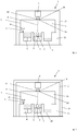
Die
Die Vorrichtung 1 dient der additiven Herstellung dreidimensionaler Objekte 2, d. h. insbesondere technischer Bauteile bzw. technischer Bauteilgruppen, durch sukzessives schichtweises selektives Belichten und damit einhergehendes sukzessives schichtweises selektives Verfestigen von Baumaterialschichten aus einem verfestigbaren Baumaterial 3, d. h. z. B. eines Metallpulvers, vermittels Laserstrahlung, vgl. Laserstrahl 4. Die selektive Verfestigung jeweiliger zu verfestigender Baumaterialschichten erfolgt auf Grundlage von objektbezogenen Baudaten. Entsprechende Baudaten beschreiben die geometrische bzw. geometrisch-konstruktive Gestalt des jeweils additiv herzustellenden Objekts 2 und können beispielsweise "geslicte" CAD-Daten des herzustellenden Objekts 2 beinhalten. Die Vorrichtung 1 kann als Laser-CUSING®-Vorrichtung, d. h. als Vorrichtung zur Durchführung selektiver Laserschmelzverfahren, ausgebildet sein.The
Die Vorrichtung 1 umfasst die zur Durchführung additiver Bauvorgänge erforderlichen Funktionskomponenten; in den Fig. ist lediglich eine Beschichtungseinrichtung 5 und eine Belichtungseinrichtung 6 gezeigt.The
Die Beschichtungseinrichtung 5 ist zur Ausbildung selektiv zu belichtender bzw. selektiv zu verfestigender Baumaterialschichten in einer Bauebene der Vorrichtung 1 eingerichtet. Die Beschichtungseinrichtung 5 umfasst eine mehrere Beschichterelemente umfassende Beschichterelementbaugruppe (nicht näher bezeichnet), welche über eine Führungseinrichtung (nicht gezeigt) in, wie durch den Doppelpfeil P1 angedeutet, horizontaler Richtung in einer Prozesskammer 7 der Vorrichtung 1 bewegbar gelagert ist.The
Die Belichtungseinrichtung 6 ist zur selektiven Belichtung selektiv zu verfestigender Baumaterialschichten in der Bauebene der Vorrichtung 1 eingerichtet und umfasst hierfür eine Strahlerzeugungseinrichtung (nicht gezeigt), welche zur Erzeugung eines Laserstrahls 4 eingerichtet ist, eine Strahlablenkeinrichtung (nicht gezeigt), welche zur Ablenkung eines von der Strahlerzeugungseinrichtung erzeugten Laserstrahls 4 auf einen zu belichtenden Bereich einer selektiv zu verfestigenden Baumaterialschicht eingerichtet ist, sowie diverse optische Elemente, wie z. B. Filterelemente, Objektivelemente, Linsenelemente, etc. Die Belichtungseinrichtung 6 kann auch als Optik der Vorrichtung 1 bezeichnet bzw. erachtet werden.The
In den Fig. ist ferner ein Dosiermodul 8, ein Baumodul 9 und ein Überlaufmodul 10 dargestellt, welche an einen unteren Bereich der Prozesskammer 7 der Vorrichtung 1 angedockt sind. Die genannten Module können auch einen unteren Bereich der Prozesskammer 7 bilden.Also shown in the figures is a
Die Belichtungseinrichtung 6 ist an einer durch ein oder mehrere, z. B. profilartige bzw. -förmige, Gestellkonstruktionselemente (nicht näher bezeichnet) gebildete bzw. solche umfassende Gehäusekonstruktion 11 wärmeentkoppelt beabstandet von der Prozesskammer 7 angeordnet. Unter einer wärmeentkoppelt beabstandeten Anordnung oder Ausbildung der Belichtungseinrichtung 6, d. h. insbesondere der der Belichtungseinrichtung 6 zugehörigen Strahlablenkeinrichtung, relativ zu der Prozesskammer 7 ist zu verstehen, dass keine Wärme (thermische Energie), welche gegebenenfalls zu einer unerwünschten Änderung der Positionierung, d. h. der Ausrichtung und/oder Anordnung, der Belichtungseinrichtung 6 (z. B. relativ zu einer Referenzpositionierung) führen könnte, von der Prozesskammer 7 auf die Belichtungseinrichtung 6 übertragen werden kann. Die Belichtungseinrichtung 6 ist derart räumlich von der Prozesskammer 7 beabstandet, dass keine Wärmeübertragung von der Prozesskammer 7 auf die Belichtungseinrichtung 6 möglich ist. Die Belichtungseinrichtung 6 ist in thermischer Hinsicht also völlig von der Prozesskammer 7 entkoppelt.The
Ersichtlich ist zwischen der Belichtungseinrichtung 6 und der Prozesskammer 7 ein einen Abstand zwischen der Belichtungseinrichtung 6 und der Prozesskammer 7 definierender Spaltraum 12 gebildet. Der Spaltraum 12 kann einen Abstand von einigen Millimetern, d. h. insbesondere einen Abstand von wenigstens einem Millimeter, definieren. Zwischen der Belichtungseinrichtung 6 und der Prozesskammer 7 besteht demnach kein physikalischer, d. h. insbesondere kein mechanischer, Kontakt, welcher eine Wärmeübertragung von der Prozesskammer 7 auf die Belichtungseinrichtung 6 ermöglichen könnte.As can be seen, a
Mit anderen Worten ist es durch die wärmeentkoppelt beabstandete Anordnung der Belichtungseinrichtung 6 von der Prozesskammer 7 nicht möglich ist, dass die sich im Betrieb der Vorrichtung 1 aufgrund der prozessbedingt entstehenden Prozesswärme erwärmende Prozesskammer 7 einen negativen Einfluss auf die Positionierung der Belichtungseinrichtung 6 hat.In other words, it is not possible by the heat-decoupled spaced arrangement of the
In dem in
In dem in
Dies ist konstruktiv derart realisiert, dass die Belichtungseinrichtung 6 an einem ersten Gestellkonstruktionsabschnitt 11a und die Prozesskammer 7 an einem weiteren Gestellkonstruktionsabschnitt 11 b angeordnet ist, wobei der erste Gestellkonstruktionsabschnitt 11a derart beabstandet von dem weiteren Gestellkonstruktionsabschnitt 11 b angeordnet ist, dass eine Änderung der Positionierung der Belichtungseinrichtung 6 an der Gestellkonstruktion 11 aufgrund der im Betrieb der Vorrichtung 1 über die Prozesskammer 7 in die Gestellkonstruktion 11 eingebrachten thermischen Energie nicht erfolgt bzw. nicht möglich ist.This is structurally realized in such a way that the
In dem in
Schließlich ist in dem in
In dem in
Die beiden Gestellkonstruktionen 11, 13 sind in dem in
In dem in
Claims (8)
eine Prozesskammer (7), in welcher die sukzessive schichtweise selektive Belichtung und die damit einhergehende sukzessive schichtweise selektive Verfestigung jeweiliger Baumaterialschichten aus einem vermittels eines Laserstrahls (4) verfestigbaren Baumaterial (3) erfolgt, und
eine Belichtungseinrichtung (6), welche zur Erzeugung eines Laserstrahls (4) zur selektiven Belichtung und damit einhergehenden Verfestigung jeweiliger Baumaterialschichten eingerichtet ist, dadurch gekennzeichnet, dass
die Belichtungseinrichtung (6) an einer Gehäusekonstruktion (11) wärmeentkoppelt beabstandet von der Prozesskammer (7) angeordnet oder ausgebildet ist.Device (1) for the additive production of three-dimensional objects (2) by successive layerwise selective exposure and consequent successive layerwise selective solidification of building material layers from a building material (3) solidifiable by means of a laser beam (4)
a process chamber (7) in which the successive layer-wise selective exposure and the concomitant successive layer-by-layer selective solidification of respective building material layers from a by means of a laser beam (4) solidifiable building material (3), and
an exposure device (6), which is set up to generate a laser beam (4) for the selective exposure and concomitant solidification of respective building material layers, characterized in that
the exposure device (6) is arranged or formed on a housing construction (11) at a distance from the process chamber (7) in a heat-decoupled manner.
Priority Applications (1)
| Application Number | Priority Date | Filing Date | Title |
|---|---|---|---|
| EP18203050.2A EP3466650B1 (en) | 2016-11-15 | 2017-06-27 | Device for additive production of three-dimensional objects |
Applications Claiming Priority (1)
| Application Number | Priority Date | Filing Date | Title |
|---|---|---|---|
| DE102016121951.7A DE102016121951A1 (en) | 2016-11-15 | 2016-11-15 | Device for the additive production of three-dimensional objects |
Related Child Applications (2)
| Application Number | Title | Priority Date | Filing Date |
|---|---|---|---|
| EP18203050.2A Division EP3466650B1 (en) | 2016-11-15 | 2017-06-27 | Device for additive production of three-dimensional objects |
| EP18203050.2A Division-Into EP3466650B1 (en) | 2016-11-15 | 2017-06-27 | Device for additive production of three-dimensional objects |
Publications (2)
| Publication Number | Publication Date |
|---|---|
| EP3321068A1 true EP3321068A1 (en) | 2018-05-16 |
| EP3321068B1 EP3321068B1 (en) | 2020-11-18 |
Family
ID=59227610
Family Applications (2)
| Application Number | Title | Priority Date | Filing Date |
|---|---|---|---|
| EP17178085.1A Active EP3321068B1 (en) | 2016-11-15 | 2017-06-27 | Apparatus for additive manufacturing of three-dimensional objects |
| EP18203050.2A Active EP3466650B1 (en) | 2016-11-15 | 2017-06-27 | Device for additive production of three-dimensional objects |
Family Applications After (1)
| Application Number | Title | Priority Date | Filing Date |
|---|---|---|---|
| EP18203050.2A Active EP3466650B1 (en) | 2016-11-15 | 2017-06-27 | Device for additive production of three-dimensional objects |
Country Status (5)
| Country | Link |
|---|---|
| US (1) | US20180133799A1 (en) |
| EP (2) | EP3321068B1 (en) |
| JP (2) | JP2018080388A (en) |
| CN (1) | CN108067617B (en) |
| DE (1) | DE102016121951A1 (en) |
Cited By (1)
| Publication number | Priority date | Publication date | Assignee | Title |
|---|---|---|---|---|
| WO2023222252A1 (en) * | 2022-05-16 | 2023-11-23 | Dmg Mori Additive Gmbh | Additive manufacturing device with decoupled process chamber and additive manufacturing method |
Families Citing this family (4)
| Publication number | Priority date | Publication date | Assignee | Title |
|---|---|---|---|---|
| WO2019096421A1 (en) * | 2017-11-20 | 2019-05-23 | SLM Solutions Group AG | Apparatus and method for producing a three-dimensional work piece |
| EP3575089A1 (en) * | 2018-05-30 | 2019-12-04 | CL Schutzrechtsverwaltungs GmbH | Support structure for supporting a functional component of an apparatus for additively manufacturing a three-dimensional object |
| CN115697594A (en) * | 2020-05-27 | 2023-02-03 | 速尔特技术有限公司 | Print cartridge for additive manufacturing |
| WO2024003264A1 (en) * | 2022-07-01 | 2024-01-04 | Freemelt Ab | Additive manufacturing using a particle beam |
Citations (2)
| Publication number | Priority date | Publication date | Assignee | Title |
|---|---|---|---|---|
| EP1600282A1 (en) * | 2004-05-28 | 2005-11-30 | 3D Systems, Inc. | Method and apparatus for heating and flattening a parked powder wave |
| WO2014012764A1 (en) * | 2012-07-18 | 2014-01-23 | Eos Gmbh Electro Optical Systems | Device and method for layer-by-layer production of a three-dimensional object |
Family Cites Families (22)
| Publication number | Priority date | Publication date | Assignee | Title |
|---|---|---|---|---|
| JPS5410495A (en) * | 1977-06-23 | 1979-01-26 | Mitsubishi Electric Corp | Laser working apparatus with reflector |
| US5252264A (en) * | 1991-11-08 | 1993-10-12 | Dtm Corporation | Apparatus and method for producing parts with multi-directional powder delivery |
| DE9400346U1 (en) * | 1994-01-11 | 1994-03-10 | Eos Electro Optical Syst | Device for producing a three-dimensional object |
| FR2774931B1 (en) | 1998-02-19 | 2000-04-28 | Arnaud Hory | METHOD OF RAPID PROTOTYPING BY LASER POWDER SINTERING AND ASSOCIATED DEVICE |
| JP2001053361A (en) * | 1999-08-11 | 2001-02-23 | Ishikawajima Harima Heavy Ind Co Ltd | Surface plate for laser device |
| DE10053741C1 (en) * | 2000-10-30 | 2002-02-21 | Concept Laser Gmbh | Machine for sintering, removing material from or marking surface with laser beam uses trolleys which include container for workpieces and have working platform whose height can be adjusted |
| WO2002042023A1 (en) * | 2000-11-27 | 2002-05-30 | National University Of Singapore | Method and apparatus for creating a three-dimensional metal part using high-temperature direct laser melting |
| PT1362132E (en) * | 2001-02-14 | 2006-09-29 | Starck H C Inc | REGENERATION OF A TANTALO SPRAY TARGET |
| DE10342882A1 (en) | 2003-09-15 | 2005-05-19 | Trumpf Werkzeugmaschinen Gmbh + Co. Kg | Apparatus and method for producing a three-dimensional shaped body |
| DE102004057865B4 (en) | 2004-11-30 | 2008-01-10 | Cl Schutzrechtsverwaltungs Gmbh | Device for producing a three-dimensional object |
| DE102004057866B4 (en) | 2004-11-30 | 2010-06-10 | Cl Schutzrechtsverwaltungs Gmbh | Device for producing three-dimensional objects |
| US7585450B2 (en) * | 2005-09-30 | 2009-09-08 | 3D Systems, Inc. | Rapid prototyping and manufacturing system and method |
| GB0816308D0 (en) * | 2008-09-05 | 2008-10-15 | Mtt Technologies Ltd | Optical module |
| JP5364439B2 (en) | 2009-05-15 | 2013-12-11 | パナソニック株式会社 | Manufacturing method of three-dimensional shaped object |
| DE202009013899U1 (en) * | 2009-10-13 | 2010-02-18 | Trumpf Werkzeugmaschinen Gmbh + Co. Kg | Shielding device on a machining head and machining head and processing machine with a shielding device |
| JP4857377B2 (en) | 2009-12-18 | 2012-01-18 | 株式会社アマダ | 3D object manufacturing equipment |
| DE102010015657A1 (en) * | 2010-04-20 | 2011-10-20 | Valeo Schalter Und Sensoren Gmbh | Sensor assembly for detecting the temperature in the interior of a vehicle and device for determining the temperature in the interior of a vehicle |
| US9063305B2 (en) * | 2012-11-26 | 2015-06-23 | Avago Technologies General Ip (Singapore) Pte. Ltd. | Methods and systems for dissipating heat in optical communications modules |
| JP2014125643A (en) * | 2012-12-25 | 2014-07-07 | Honda Motor Co Ltd | Apparatus for three-dimensional shaping and method for three-dimensional shaping |
| DE102013109162A1 (en) * | 2013-08-23 | 2015-02-26 | Fit Fruth Innovative Technologien Gmbh | Device for producing three-dimensional objects |
| DE102015200134A1 (en) * | 2015-01-08 | 2016-07-14 | Trumpf Laser- Und Systemtechnik Gmbh | Modular SLM or SLS processing machine |
| US11358224B2 (en) | 2015-11-16 | 2022-06-14 | Renishaw Plc | Module for additive manufacturing apparatus and method |
-
2016
- 2016-11-15 DE DE102016121951.7A patent/DE102016121951A1/en not_active Withdrawn
-
2017
- 2017-06-27 EP EP17178085.1A patent/EP3321068B1/en active Active
- 2017-06-27 EP EP18203050.2A patent/EP3466650B1/en active Active
- 2017-08-28 CN CN201710748570.2A patent/CN108067617B/en not_active Expired - Fee Related
- 2017-11-08 JP JP2017215278A patent/JP2018080388A/en active Pending
- 2017-11-15 US US15/813,560 patent/US20180133799A1/en not_active Abandoned
-
2020
- 2020-07-31 JP JP2020130494A patent/JP2020180379A/en not_active Ceased
Patent Citations (2)
| Publication number | Priority date | Publication date | Assignee | Title |
|---|---|---|---|---|
| EP1600282A1 (en) * | 2004-05-28 | 2005-11-30 | 3D Systems, Inc. | Method and apparatus for heating and flattening a parked powder wave |
| WO2014012764A1 (en) * | 2012-07-18 | 2014-01-23 | Eos Gmbh Electro Optical Systems | Device and method for layer-by-layer production of a three-dimensional object |
Cited By (1)
| Publication number | Priority date | Publication date | Assignee | Title |
|---|---|---|---|---|
| WO2023222252A1 (en) * | 2022-05-16 | 2023-11-23 | Dmg Mori Additive Gmbh | Additive manufacturing device with decoupled process chamber and additive manufacturing method |
Also Published As
| Publication number | Publication date |
|---|---|
| CN108067617B (en) | 2020-06-09 |
| CN108067617A (en) | 2018-05-25 |
| EP3466650A1 (en) | 2019-04-10 |
| US20180133799A1 (en) | 2018-05-17 |
| JP2018080388A (en) | 2018-05-24 |
| EP3466650B1 (en) | 2021-11-10 |
| EP3321068B1 (en) | 2020-11-18 |
| DE102016121951A1 (en) | 2018-05-17 |
| JP2020180379A (en) | 2020-11-05 |
Similar Documents
| Publication | Publication Date | Title |
|---|---|---|
| EP3321068B1 (en) | Apparatus for additive manufacturing of three-dimensional objects | |
| EP2857139B1 (en) | Device for laser processing materials with a laser head movable along a space direction | |
| EP3321009B1 (en) | Apparatus for additive manufacturing of three-dimensional objects | |
| EP3183083B2 (en) | Method for producing a three-dimensional object | |
| EP3036086B1 (en) | Device for producing three-dimensional objects | |
| EP3050648B1 (en) | Device and method for producing or repairing a three-dimensional object | |
| WO2015197039A1 (en) | Rapid manufacturing method and device for the same comprising oppositely-directed protective gas streams parallel to the powder layer | |
| EP2335848A1 (en) | Optical irradiation unit for an assembly for producing workpieces by means of irradiating powder layers with laser radiation | |
| EP3620245B1 (en) | Flow method for additive manufacturing apparatus | |
| EP3372404B1 (en) | Device for additive production of three-dimensional objects | |
| WO2016207123A1 (en) | Apparatus for the additive manufacturing of at least one three-dimensional object | |
| EP3377236B1 (en) | Device for the generative production of a three-dimensional object | |
| DE102013011675A1 (en) | Method for additive component production with reduced thermal gradients | |
| EP3362835B1 (en) | Exposure optical system and device for producing a three-dimensional object | |
| DE102010046467A1 (en) | Device, useful for manufacturing, repairing and/or replacing component, preferably aircraft component by powder solidifiable by radiation energy of radiation energy source, comprises fixed construction platform with frame | |
| DE102016110593A1 (en) | Method and apparatus for producing three-dimensional objects by selectively solidifying a build-up material applied in layers | |
| EP2796273B1 (en) | Protection device for generative production methods, production device provided with same and generative production method that can be carried out with same | |
| EP3335858A1 (en) | Method for the additive production of a three-dimensional object | |
| DE102016205437A1 (en) | Device and method for producing or repairing a three-dimensional object | |
| WO2017153195A1 (en) | Apparatus for the additive manufacturing of a three-dimensional object | |
| EP3321065A1 (en) | Apparatus for additive manufacturing of three-dimensional objects | |
| EP3321008B1 (en) | Apparatus for additive manufacturing of three-dimensional objects | |
| DE102014207001A1 (en) | Method and device for improving the material quality in generative manufacturing processes | |
| EP3335856A1 (en) | Exposure device for an apparatus for additive manufacturing of three-dimensional objects | |
| DE102018206361A1 (en) | Process for the generative production of a component and plant for additive manufacturing |
Legal Events
| Date | Code | Title | Description |
|---|---|---|---|
| PUAI | Public reference made under article 153(3) epc to a published international application that has entered the european phase |
Free format text: ORIGINAL CODE: 0009012 |
|
| STAA | Information on the status of an ep patent application or granted ep patent |
Free format text: STATUS: THE APPLICATION HAS BEEN PUBLISHED |
|
| AK | Designated contracting states |
Kind code of ref document: A1 Designated state(s): AL AT BE BG CH CY CZ DE DK EE ES FI FR GB GR HR HU IE IS IT LI LT LU LV MC MK MT NL NO PL PT RO RS SE SI SK SM TR |
|
| AX | Request for extension of the european patent |
Extension state: BA ME |
|
| STAA | Information on the status of an ep patent application or granted ep patent |
Free format text: STATUS: REQUEST FOR EXAMINATION WAS MADE |
|
| 17P | Request for examination filed |
Effective date: 20181030 |
|
| RBV | Designated contracting states (corrected) |
Designated state(s): AL AT BE BG CH CY CZ DE DK EE ES FI FR GB GR HR HU IE IS IT LI LT LU LV MC MK MT NL NO PL PT RO RS SE SI SK SM TR |
|
| GRAP | Despatch of communication of intention to grant a patent |
Free format text: ORIGINAL CODE: EPIDOSNIGR1 |
|
| STAA | Information on the status of an ep patent application or granted ep patent |
Free format text: STATUS: GRANT OF PATENT IS INTENDED |
|
| RIC1 | Information provided on ipc code assigned before grant |
Ipc: B33Y 10/00 20150101ALI20200611BHEP Ipc: B29C 64/264 20170101ALI20200611BHEP Ipc: B29C 64/25 20170101AFI20200611BHEP Ipc: B33Y 30/00 20150101ALI20200611BHEP |
|
| INTG | Intention to grant announced |
Effective date: 20200629 |
|
| GRAS | Grant fee paid |
Free format text: ORIGINAL CODE: EPIDOSNIGR3 |
|
| GRAA | (expected) grant |
Free format text: ORIGINAL CODE: 0009210 |
|
| STAA | Information on the status of an ep patent application or granted ep patent |
Free format text: STATUS: THE PATENT HAS BEEN GRANTED |
|
| AK | Designated contracting states |
Kind code of ref document: B1 Designated state(s): AL AT BE BG CH CY CZ DE DK EE ES FI FR GB GR HR HU IE IS IT LI LT LU LV MC MK MT NL NO PL PT RO RS SE SI SK SM TR |
|
| REG | Reference to a national code |
Ref country code: GB Ref legal event code: FG4D Free format text: NOT ENGLISH |
|
| REG | Reference to a national code |
Ref country code: CH Ref legal event code: EP |
|
| REG | Reference to a national code |
Ref country code: IE Ref legal event code: FG4D Free format text: LANGUAGE OF EP DOCUMENT: GERMAN |
|
| REG | Reference to a national code |
Ref country code: DE Ref legal event code: R096 Ref document number: 502017008228 Country of ref document: DE |
|
| REG | Reference to a national code |
Ref country code: AT Ref legal event code: REF Ref document number: 1335266 Country of ref document: AT Kind code of ref document: T Effective date: 20201215 |
|
| REG | Reference to a national code |
Ref country code: NL Ref legal event code: MP Effective date: 20201118 |
|
| PG25 | Lapsed in a contracting state [announced via postgrant information from national office to epo] |
Ref country code: NO Free format text: LAPSE BECAUSE OF FAILURE TO SUBMIT A TRANSLATION OF THE DESCRIPTION OR TO PAY THE FEE WITHIN THE PRESCRIBED TIME-LIMIT Effective date: 20210218 Ref country code: PT Free format text: LAPSE BECAUSE OF FAILURE TO SUBMIT A TRANSLATION OF THE DESCRIPTION OR TO PAY THE FEE WITHIN THE PRESCRIBED TIME-LIMIT Effective date: 20210318 Ref country code: RS Free format text: LAPSE BECAUSE OF FAILURE TO SUBMIT A TRANSLATION OF THE DESCRIPTION OR TO PAY THE FEE WITHIN THE PRESCRIBED TIME-LIMIT Effective date: 20201118 Ref country code: GR Free format text: LAPSE BECAUSE OF FAILURE TO SUBMIT A TRANSLATION OF THE DESCRIPTION OR TO PAY THE FEE WITHIN THE PRESCRIBED TIME-LIMIT Effective date: 20210219 Ref country code: FI Free format text: LAPSE BECAUSE OF FAILURE TO SUBMIT A TRANSLATION OF THE DESCRIPTION OR TO PAY THE FEE WITHIN THE PRESCRIBED TIME-LIMIT Effective date: 20201118 |
|
| PG25 | Lapsed in a contracting state [announced via postgrant information from national office to epo] |
Ref country code: IS Free format text: LAPSE BECAUSE OF FAILURE TO SUBMIT A TRANSLATION OF THE DESCRIPTION OR TO PAY THE FEE WITHIN THE PRESCRIBED TIME-LIMIT Effective date: 20210318 Ref country code: LV Free format text: LAPSE BECAUSE OF FAILURE TO SUBMIT A TRANSLATION OF THE DESCRIPTION OR TO PAY THE FEE WITHIN THE PRESCRIBED TIME-LIMIT Effective date: 20201118 Ref country code: PL Free format text: LAPSE BECAUSE OF FAILURE TO SUBMIT A TRANSLATION OF THE DESCRIPTION OR TO PAY THE FEE WITHIN THE PRESCRIBED TIME-LIMIT Effective date: 20201118 Ref country code: BG Free format text: LAPSE BECAUSE OF FAILURE TO SUBMIT A TRANSLATION OF THE DESCRIPTION OR TO PAY THE FEE WITHIN THE PRESCRIBED TIME-LIMIT Effective date: 20210218 Ref country code: SE Free format text: LAPSE BECAUSE OF FAILURE TO SUBMIT A TRANSLATION OF THE DESCRIPTION OR TO PAY THE FEE WITHIN THE PRESCRIBED TIME-LIMIT Effective date: 20201118 |
|
| REG | Reference to a national code |
Ref country code: LT Ref legal event code: MG9D |
|
| PG25 | Lapsed in a contracting state [announced via postgrant information from national office to epo] |
Ref country code: HR Free format text: LAPSE BECAUSE OF FAILURE TO SUBMIT A TRANSLATION OF THE DESCRIPTION OR TO PAY THE FEE WITHIN THE PRESCRIBED TIME-LIMIT Effective date: 20201118 |
|
| PG25 | Lapsed in a contracting state [announced via postgrant information from national office to epo] |
Ref country code: CZ Free format text: LAPSE BECAUSE OF FAILURE TO SUBMIT A TRANSLATION OF THE DESCRIPTION OR TO PAY THE FEE WITHIN THE PRESCRIBED TIME-LIMIT Effective date: 20201118 Ref country code: EE Free format text: LAPSE BECAUSE OF FAILURE TO SUBMIT A TRANSLATION OF THE DESCRIPTION OR TO PAY THE FEE WITHIN THE PRESCRIBED TIME-LIMIT Effective date: 20201118 Ref country code: LT Free format text: LAPSE BECAUSE OF FAILURE TO SUBMIT A TRANSLATION OF THE DESCRIPTION OR TO PAY THE FEE WITHIN THE PRESCRIBED TIME-LIMIT Effective date: 20201118 Ref country code: SM Free format text: LAPSE BECAUSE OF FAILURE TO SUBMIT A TRANSLATION OF THE DESCRIPTION OR TO PAY THE FEE WITHIN THE PRESCRIBED TIME-LIMIT Effective date: 20201118 Ref country code: SK Free format text: LAPSE BECAUSE OF FAILURE TO SUBMIT A TRANSLATION OF THE DESCRIPTION OR TO PAY THE FEE WITHIN THE PRESCRIBED TIME-LIMIT Effective date: 20201118 Ref country code: RO Free format text: LAPSE BECAUSE OF FAILURE TO SUBMIT A TRANSLATION OF THE DESCRIPTION OR TO PAY THE FEE WITHIN THE PRESCRIBED TIME-LIMIT Effective date: 20201118 |
|
| REG | Reference to a national code |
Ref country code: DE Ref legal event code: R026 Ref document number: 502017008228 Country of ref document: DE |
|
| PLBI | Opposition filed |
Free format text: ORIGINAL CODE: 0009260 |
|
| PG25 | Lapsed in a contracting state [announced via postgrant information from national office to epo] |
Ref country code: DK Free format text: LAPSE BECAUSE OF FAILURE TO SUBMIT A TRANSLATION OF THE DESCRIPTION OR TO PAY THE FEE WITHIN THE PRESCRIBED TIME-LIMIT Effective date: 20201118 |
|
| PLAX | Notice of opposition and request to file observation + time limit sent |
Free format text: ORIGINAL CODE: EPIDOSNOBS2 |
|
| 26 | Opposition filed |
Opponent name: SLM SOLUTIONS GROUP AG Effective date: 20210811 |
|
| PG25 | Lapsed in a contracting state [announced via postgrant information from national office to epo] |
Ref country code: NL Free format text: LAPSE BECAUSE OF FAILURE TO SUBMIT A TRANSLATION OF THE DESCRIPTION OR TO PAY THE FEE WITHIN THE PRESCRIBED TIME-LIMIT Effective date: 20201118 Ref country code: AL Free format text: LAPSE BECAUSE OF FAILURE TO SUBMIT A TRANSLATION OF THE DESCRIPTION OR TO PAY THE FEE WITHIN THE PRESCRIBED TIME-LIMIT Effective date: 20201118 Ref country code: IT Free format text: LAPSE BECAUSE OF FAILURE TO SUBMIT A TRANSLATION OF THE DESCRIPTION OR TO PAY THE FEE WITHIN THE PRESCRIBED TIME-LIMIT Effective date: 20201118 |
|
| PG25 | Lapsed in a contracting state [announced via postgrant information from national office to epo] |
Ref country code: SI Free format text: LAPSE BECAUSE OF FAILURE TO SUBMIT A TRANSLATION OF THE DESCRIPTION OR TO PAY THE FEE WITHIN THE PRESCRIBED TIME-LIMIT Effective date: 20201118 |
|
| PLBB | Reply of patent proprietor to notice(s) of opposition received |
Free format text: ORIGINAL CODE: EPIDOSNOBS3 |
|
| PG25 | Lapsed in a contracting state [announced via postgrant information from national office to epo] |
Ref country code: MC Free format text: LAPSE BECAUSE OF FAILURE TO SUBMIT A TRANSLATION OF THE DESCRIPTION OR TO PAY THE FEE WITHIN THE PRESCRIBED TIME-LIMIT Effective date: 20201118 Ref country code: ES Free format text: LAPSE BECAUSE OF FAILURE TO SUBMIT A TRANSLATION OF THE DESCRIPTION OR TO PAY THE FEE WITHIN THE PRESCRIBED TIME-LIMIT Effective date: 20201118 |
|
| REG | Reference to a national code |
Ref country code: CH Ref legal event code: PL |
|
| REG | Reference to a national code |
Ref country code: BE Ref legal event code: MM Effective date: 20210630 |
|
| PG25 | Lapsed in a contracting state [announced via postgrant information from national office to epo] |
Ref country code: LU Free format text: LAPSE BECAUSE OF NON-PAYMENT OF DUE FEES Effective date: 20210627 |
|
| PG25 | Lapsed in a contracting state [announced via postgrant information from national office to epo] |
Ref country code: LI Free format text: LAPSE BECAUSE OF NON-PAYMENT OF DUE FEES Effective date: 20210630 Ref country code: IE Free format text: LAPSE BECAUSE OF NON-PAYMENT OF DUE FEES Effective date: 20210627 Ref country code: CH Free format text: LAPSE BECAUSE OF NON-PAYMENT OF DUE FEES Effective date: 20210630 |
|
| PG25 | Lapsed in a contracting state [announced via postgrant information from national office to epo] |
Ref country code: IS Free format text: LAPSE BECAUSE OF FAILURE TO SUBMIT A TRANSLATION OF THE DESCRIPTION OR TO PAY THE FEE WITHIN THE PRESCRIBED TIME-LIMIT Effective date: 20210318 |
|
| PG25 | Lapsed in a contracting state [announced via postgrant information from national office to epo] |
Ref country code: BE Free format text: LAPSE BECAUSE OF NON-PAYMENT OF DUE FEES Effective date: 20210630 |
|
| REG | Reference to a national code |
Ref country code: DE Ref legal event code: R081 Ref document number: 502017008228 Country of ref document: DE Owner name: CONCEPT LASER GMBH, DE Free format text: FORMER OWNER: CL SCHUTZRECHTSVERWALTUNGS GMBH, 96215 LICHTENFELS, DE |
|
| RAP2 | Party data changed (patent owner data changed or rights of a patent transferred) |
Owner name: CONCEPT LASER GMBH |
|
| REG | Reference to a national code |
Ref country code: GB Ref legal event code: 732E Free format text: REGISTERED BETWEEN 20230406 AND 20230412 |
|
| P01 | Opt-out of the competence of the unified patent court (upc) registered |
Effective date: 20230517 |
|
| PG25 | Lapsed in a contracting state [announced via postgrant information from national office to epo] |
Ref country code: CY Free format text: LAPSE BECAUSE OF FAILURE TO SUBMIT A TRANSLATION OF THE DESCRIPTION OR TO PAY THE FEE WITHIN THE PRESCRIBED TIME-LIMIT Effective date: 20201118 |
|
| PG25 | Lapsed in a contracting state [announced via postgrant information from national office to epo] |
Ref country code: HU Free format text: LAPSE BECAUSE OF FAILURE TO SUBMIT A TRANSLATION OF THE DESCRIPTION OR TO PAY THE FEE WITHIN THE PRESCRIBED TIME-LIMIT; INVALID AB INITIO Effective date: 20170627 |
|
| PGFP | Annual fee paid to national office [announced via postgrant information from national office to epo] |
Ref country code: FR Payment date: 20230523 Year of fee payment: 7 Ref country code: DE Payment date: 20230523 Year of fee payment: 7 |
|
| REG | Reference to a national code |
Ref country code: AT Ref legal event code: MM01 Ref document number: 1335266 Country of ref document: AT Kind code of ref document: T Effective date: 20220627 |
|
| PLAB | Opposition data, opponent's data or that of the opponent's representative modified |
Free format text: ORIGINAL CODE: 0009299OPPO |
|
| R26 | Opposition filed (corrected) |
Opponent name: NIKON SLM SOLUTIONS AG Effective date: 20210811 |
|
| PG25 | Lapsed in a contracting state [announced via postgrant information from national office to epo] |
Ref country code: AT Free format text: LAPSE BECAUSE OF NON-PAYMENT OF DUE FEES Effective date: 20220627 |
|
| PGFP | Annual fee paid to national office [announced via postgrant information from national office to epo] |
Ref country code: GB Payment date: 20230523 Year of fee payment: 7 |
|
| APBM | Appeal reference recorded |
Free format text: ORIGINAL CODE: EPIDOSNREFNO |
|
| APBP | Date of receipt of notice of appeal recorded |
Free format text: ORIGINAL CODE: EPIDOSNNOA2O |
|
| APAH | Appeal reference modified |
Free format text: ORIGINAL CODE: EPIDOSCREFNO |
|
| APBU | Appeal procedure closed |
Free format text: ORIGINAL CODE: EPIDOSNNOA9O |