EP3183083B2 - Method for producing a three-dimensional object - Google Patents
Method for producing a three-dimensional object Download PDFInfo
- Publication number
- EP3183083B2 EP3183083B2 EP15753354.8A EP15753354A EP3183083B2 EP 3183083 B2 EP3183083 B2 EP 3183083B2 EP 15753354 A EP15753354 A EP 15753354A EP 3183083 B2 EP3183083 B2 EP 3183083B2
- Authority
- EP
- European Patent Office
- Prior art keywords
- objects
- dimensional object
- support structure
- sub
- partial
- Prior art date
- Legal status (The legal status is an assumption and is not a legal conclusion. Google has not performed a legal analysis and makes no representation as to the accuracy of the status listed.)
- Active
Links
- 238000004519 manufacturing process Methods 0.000 title claims description 18
- 238000000034 method Methods 0.000 claims description 66
- 230000015572 biosynthetic process Effects 0.000 claims description 27
- 239000000463 material Substances 0.000 claims description 15
- 230000005855 radiation Effects 0.000 claims description 12
- 238000010438 heat treatment Methods 0.000 claims description 8
- 238000002844 melting Methods 0.000 claims description 8
- 238000007711 solidification Methods 0.000 claims description 8
- 230000008023 solidification Effects 0.000 claims description 8
- 238000000149 argon plasma sintering Methods 0.000 claims description 7
- 230000008018 melting Effects 0.000 claims description 7
- 230000000694 effects Effects 0.000 claims description 6
- 239000011248 coating agent Substances 0.000 claims description 2
- 238000000576 coating method Methods 0.000 claims description 2
- 230000001678 irradiating effect Effects 0.000 claims 1
- 239000004566 building material Substances 0.000 description 19
- 239000000843 powder Substances 0.000 description 8
- 229910052751 metal Inorganic materials 0.000 description 5
- 239000002184 metal Substances 0.000 description 5
- 239000004033 plastic Substances 0.000 description 5
- 229920003023 plastic Polymers 0.000 description 5
- 238000010309 melting process Methods 0.000 description 4
- 239000000654 additive Substances 0.000 description 3
- 230000000996 additive effect Effects 0.000 description 3
- XEEYBQQBJWHFJM-UHFFFAOYSA-N Iron Chemical compound [Fe] XEEYBQQBJWHFJM-UHFFFAOYSA-N 0.000 description 2
- 230000004308 accommodation Effects 0.000 description 2
- 239000004035 construction material Substances 0.000 description 2
- 230000001771 impaired effect Effects 0.000 description 2
- 230000001788 irregular Effects 0.000 description 2
- 239000000203 mixture Substances 0.000 description 2
- 238000012805 post-processing Methods 0.000 description 2
- 238000012545 processing Methods 0.000 description 2
- 238000003466 welding Methods 0.000 description 2
- 239000004696 Poly ether ether ketone Substances 0.000 description 1
- 239000004952 Polyamide Substances 0.000 description 1
- 206010040925 Skin striae Diseases 0.000 description 1
- 208000031439 Striae Distensae Diseases 0.000 description 1
- 229910052782 aluminium Inorganic materials 0.000 description 1
- XAGFODPZIPBFFR-UHFFFAOYSA-N aluminium Chemical compound [Al] XAGFODPZIPBFFR-UHFFFAOYSA-N 0.000 description 1
- 239000011324 bead Substances 0.000 description 1
- JUPQTSLXMOCDHR-UHFFFAOYSA-N benzene-1,4-diol;bis(4-fluorophenyl)methanone Chemical compound OC1=CC=C(O)C=C1.C1=CC(F)=CC=C1C(=O)C1=CC=C(F)C=C1 JUPQTSLXMOCDHR-UHFFFAOYSA-N 0.000 description 1
- 230000001419 dependent effect Effects 0.000 description 1
- 238000011161 development Methods 0.000 description 1
- 230000018109 developmental process Effects 0.000 description 1
- 230000005670 electromagnetic radiation Effects 0.000 description 1
- 238000005516 engineering process Methods 0.000 description 1
- 229910052742 iron Inorganic materials 0.000 description 1
- 229910001092 metal group alloy Inorganic materials 0.000 description 1
- 150000002739 metals Chemical class 0.000 description 1
- 229920002647 polyamide Polymers 0.000 description 1
- 229920002530 polyetherether ketone Polymers 0.000 description 1
Images

Classifications
-
- B—PERFORMING OPERATIONS; TRANSPORTING
- B22—CASTING; POWDER METALLURGY
- B22F—WORKING METALLIC POWDER; MANUFACTURE OF ARTICLES FROM METALLIC POWDER; MAKING METALLIC POWDER; APPARATUS OR DEVICES SPECIALLY ADAPTED FOR METALLIC POWDER
- B22F3/00—Manufacture of workpieces or articles from metallic powder characterised by the manner of compacting or sintering; Apparatus specially adapted therefor ; Presses and furnaces
- B22F3/24—After-treatment of workpieces or articles
-
- B—PERFORMING OPERATIONS; TRANSPORTING
- B22—CASTING; POWDER METALLURGY
- B22F—WORKING METALLIC POWDER; MANUFACTURE OF ARTICLES FROM METALLIC POWDER; MAKING METALLIC POWDER; APPARATUS OR DEVICES SPECIALLY ADAPTED FOR METALLIC POWDER
- B22F10/00—Additive manufacturing of workpieces or articles from metallic powder
- B22F10/20—Direct sintering or melting
- B22F10/28—Powder bed fusion, e.g. selective laser melting [SLM] or electron beam melting [EBM]
-
- B—PERFORMING OPERATIONS; TRANSPORTING
- B22—CASTING; POWDER METALLURGY
- B22F—WORKING METALLIC POWDER; MANUFACTURE OF ARTICLES FROM METALLIC POWDER; MAKING METALLIC POWDER; APPARATUS OR DEVICES SPECIALLY ADAPTED FOR METALLIC POWDER
- B22F10/00—Additive manufacturing of workpieces or articles from metallic powder
- B22F10/40—Structures for supporting workpieces or articles during manufacture and removed afterwards
- B22F10/47—Structures for supporting workpieces or articles during manufacture and removed afterwards characterised by structural features
-
- B—PERFORMING OPERATIONS; TRANSPORTING
- B22—CASTING; POWDER METALLURGY
- B22F—WORKING METALLIC POWDER; MANUFACTURE OF ARTICLES FROM METALLIC POWDER; MAKING METALLIC POWDER; APPARATUS OR DEVICES SPECIALLY ADAPTED FOR METALLIC POWDER
- B22F10/00—Additive manufacturing of workpieces or articles from metallic powder
- B22F10/60—Treatment of workpieces or articles after build-up
- B22F10/64—Treatment of workpieces or articles after build-up by thermal means
-
- B—PERFORMING OPERATIONS; TRANSPORTING
- B22—CASTING; POWDER METALLURGY
- B22F—WORKING METALLIC POWDER; MANUFACTURE OF ARTICLES FROM METALLIC POWDER; MAKING METALLIC POWDER; APPARATUS OR DEVICES SPECIALLY ADAPTED FOR METALLIC POWDER
- B22F5/00—Manufacture of workpieces or articles from metallic powder characterised by the special shape of the product
- B22F5/04—Manufacture of workpieces or articles from metallic powder characterised by the special shape of the product of turbine blades
-
- B—PERFORMING OPERATIONS; TRANSPORTING
- B29—WORKING OF PLASTICS; WORKING OF SUBSTANCES IN A PLASTIC STATE IN GENERAL
- B29C—SHAPING OR JOINING OF PLASTICS; SHAPING OF MATERIAL IN A PLASTIC STATE, NOT OTHERWISE PROVIDED FOR; AFTER-TREATMENT OF THE SHAPED PRODUCTS, e.g. REPAIRING
- B29C64/00—Additive manufacturing, i.e. manufacturing of three-dimensional [3D] objects by additive deposition, additive agglomeration or additive layering, e.g. by 3D printing, stereolithography or selective laser sintering
- B29C64/10—Processes of additive manufacturing
- B29C64/141—Processes of additive manufacturing using only solid materials
- B29C64/153—Processes of additive manufacturing using only solid materials using layers of powder being selectively joined, e.g. by selective laser sintering or melting
-
- B—PERFORMING OPERATIONS; TRANSPORTING
- B29—WORKING OF PLASTICS; WORKING OF SUBSTANCES IN A PLASTIC STATE IN GENERAL
- B29C—SHAPING OR JOINING OF PLASTICS; SHAPING OF MATERIAL IN A PLASTIC STATE, NOT OTHERWISE PROVIDED FOR; AFTER-TREATMENT OF THE SHAPED PRODUCTS, e.g. REPAIRING
- B29C64/00—Additive manufacturing, i.e. manufacturing of three-dimensional [3D] objects by additive deposition, additive agglomeration or additive layering, e.g. by 3D printing, stereolithography or selective laser sintering
- B29C64/40—Structures for supporting 3D objects during manufacture and intended to be sacrificed after completion thereof
-
- B—PERFORMING OPERATIONS; TRANSPORTING
- B33—ADDITIVE MANUFACTURING TECHNOLOGY
- B33Y—ADDITIVE MANUFACTURING, i.e. MANUFACTURING OF THREE-DIMENSIONAL [3-D] OBJECTS BY ADDITIVE DEPOSITION, ADDITIVE AGGLOMERATION OR ADDITIVE LAYERING, e.g. BY 3-D PRINTING, STEREOLITHOGRAPHY OR SELECTIVE LASER SINTERING
- B33Y10/00—Processes of additive manufacturing
-
- B—PERFORMING OPERATIONS; TRANSPORTING
- B22—CASTING; POWDER METALLURGY
- B22F—WORKING METALLIC POWDER; MANUFACTURE OF ARTICLES FROM METALLIC POWDER; MAKING METALLIC POWDER; APPARATUS OR DEVICES SPECIALLY ADAPTED FOR METALLIC POWDER
- B22F3/00—Manufacture of workpieces or articles from metallic powder characterised by the manner of compacting or sintering; Apparatus specially adapted therefor ; Presses and furnaces
- B22F3/10—Sintering only
- B22F2003/1042—Sintering only with support for articles to be sintered
-
- B—PERFORMING OPERATIONS; TRANSPORTING
- B22—CASTING; POWDER METALLURGY
- B22F—WORKING METALLIC POWDER; MANUFACTURE OF ARTICLES FROM METALLIC POWDER; MAKING METALLIC POWDER; APPARATUS OR DEVICES SPECIALLY ADAPTED FOR METALLIC POWDER
- B22F2999/00—Aspects linked to processes or compositions used in powder metallurgy
-
- Y—GENERAL TAGGING OF NEW TECHNOLOGICAL DEVELOPMENTS; GENERAL TAGGING OF CROSS-SECTIONAL TECHNOLOGIES SPANNING OVER SEVERAL SECTIONS OF THE IPC; TECHNICAL SUBJECTS COVERED BY FORMER USPC CROSS-REFERENCE ART COLLECTIONS [XRACs] AND DIGESTS
- Y02—TECHNOLOGIES OR APPLICATIONS FOR MITIGATION OR ADAPTATION AGAINST CLIMATE CHANGE
- Y02P—CLIMATE CHANGE MITIGATION TECHNOLOGIES IN THE PRODUCTION OR PROCESSING OF GOODS
- Y02P10/00—Technologies related to metal processing
- Y02P10/25—Process efficiency
Definitions
- the invention relates to a method for producing a three-dimensional object by sequentially solidifying layers of a powder-like building material that can be solidified by means of radiation.
- Such methods are generally generative processes for the formation or manufacture of three-dimensional objects or items, such as. B. technical components.
- the basic principle of such methods envisages forming the three-dimensional object to be produced in each case by successive or successive solidification of layers of a powder-like building material that can be solidified by means of radiation, typically laser radiation.
- Known examples of such methods are therefore laser sintering methods, or SLS methods for short, or laser melting methods, SLM methods for short.
- EP 1 614 526 A1 discloses a principle for the additive manufacturing of large-format three-dimensional components on a support structure.
- U.S. 2012/0255176 A1 discloses a principle for the additive manufacturing of three-dimensional components.
- U.S. 2006/0236544 A1 discloses a principle for the additive manufacturing of three-dimensional components.
- the invention is based on the object of specifying an improved method for producing, in particular large-format, three-dimensional objects by successively solidifying layers of a powder-like building material that can be solidified by means of radiation.
- the method according to the invention for producing a three-dimensional object by successively solidifying layers of a powder-like building material that can be solidified by means of radiation comprises the following method steps: First, a laser sintering or laser melting system with the usual components is provided. These common components are a housing with a build chamber housed therein, with a carrying device for carrying the object being provided in the build chamber. In addition, a coating device is present in order to apply build-up material in layers onto a carrier or onto a previously applied layer.
- the layers are irradiated with an irradiation device and thereby solidified at the points corresponding to the respective cross section of the object, for which purpose the irradiation device usually comprises a scanner for deflecting electromagnetic radiation from a radiation source, which is usually designed as a laser. Then a support structure is formed, this is usually done on a base such. B. a building board. In any case, the support structure should be connected to one another in its base area. The support structure is built up generatively.
- a support structure for at least partially supporting the three-dimensional object to be produced is thus formed by successive hardening of layers of the or a powder-like building material that can be hardened by means of radiation.
- a support structure is also formed, the task and function of which is explained in more detail below. It is therefore essential that, in addition to the three-dimensional object that is actually to be produced, the supporting structure is also formed by successive solidification of the or a powder-like building material that can be solidified by means of radiation. The support structure is thus formed in the same process in which the three-dimensional object actually to be produced is also formed.
- the support structure serves to store or support the three-dimensional object to be produced at least in sections, typically completely.
- the three-dimensional object to be produced is then built up successively on the support structure.
- the support structure is correspondingly to be adapted or adapted in its geometric shape, in particular in its cross section, to the geometric shape, in particular the cross section, of the three-dimensional object to be produced. In order to fulfill the support function described, the support structure therefore typically completely reproduces the cross section of the three-dimensional object to be produced.
- the support structure typically comprises at least one support element, which is used for at least partially supporting or supporting the or a part of the three-dimensional object to be produced.
- the support structure comprises a plurality of support elements of the same or different geometric shape, i. H. in particular of the same or different shape or the same or different dimensions.
- the support elements can be present in a regular or irregular arrangement.
- the support elements can, for. B. web or pillar-like and have branches.
- the support structure is typically formed on a building plate of the building chamber of the device for carrying out the method, ie in particular a device for carrying out a laser sintering process or a laser melting process.
- the three-dimensional object actually to be produced is formed simultaneously or simultaneously and thus together with the formation of the support structure or after the formation of the support structure. It is essential that the three-dimensional object is formed in segments. A plurality of individual or separate sub-objects are thus formed, each forming a specific partial cross-section of the three-dimensional object to be produced, which, as explained further below, are to be connected to one another or are connected to one another to form the three-dimensional object. Each sub-object thus forms a specific part of the overall cross-section of the three-dimensional object.
- the three-dimensional object to be produced is therefore not built up cohesively over its entire cross section. Rather, successive individual sub-objects, each forming a specific sub-area of the three-dimensional object to be produced, are built up. In terms of position, the sub-objects are typically formed relative to one another in such a way that their arrangement depicts or results in the entire three-dimensional object.
- the or a part of the sub-objects can have the same or different geometric shape, d. H. in particular of the same or different shape or the same or different dimensions.
- the specific geometric shape of the respective sub-objects depends on the sub-areas of the three-dimensional object to be produced and thus on the overall cross-section of the three-dimensional object to be produced. From this it follows that the dimensions, arrangement and orientation of corresponding sub-objects are formed as a function of the specific dimensions of the object to be produced in each case.
- the sub-objects are each supported at least in sections by the support structure.
- the support structure also ensures that the sub-objects are or will be securely arranged in their relative position to one another.
- the support structure can therefore be moved together with the sub-objects mounted or supported by it without changing the relative position of the individual sub-objects to one another, which means a considerable advantage with regard to the handling of the three-dimensional object.
- a corresponding building board together with the support structure formed on it and the sub-objects formed on it can also be moved without changing the relative position of the individual sub-objects to one another.
- the individual sub-objects are to be connected to form the three-dimensional object. It is therefore provided according to the method to form a plurality of connection areas between the individual partial objects for the at least partial connection of the partial objects while forming the three-dimensional object.
- the sub-objects are typically supported by the support structure, i. H. on this, in particular in their fixed position relative to each other, stored.
- connection areas can in principle be formed in any desired geometric shape.
- the connection areas can thus z. B. be formed point or line or areal.
- At least some of the connecting areas can also be designed, for example, as webs, bridges, stretch marks, rods and the like, or have the form of interlocking teeth or other positive-locking elements. It is essential that the connection areas connect adjacently arranged sub-objects to one another in a stable manner.
- a connection area typically connects at least two partial objects arranged directly adjacent to one another. Dimensions, arrangement and orientation of corresponding connection areas are typically designed depending on the specific dimensions of the object to be manufactured in each case.
- heat treatment can be carried out in order to reduce stresses in the overall component which is then connected.
- the fully formed three-dimensional object is removed from the support structure.
- the three-dimensional object can z. B. be removed from the support structure manually or (partially) automatically. It is of course also possible for the support structure to be removed from the three-dimensional object manually or (partially) automatically.
- the three-dimensional object actually to be produced is formed in at least two stages.
- the individual sub-objects are formed in addition to the support structure.
- the individual sub-objects are supported by the support structure.
- the support also includes a (temporary) securing of the relative position of the individual sub-objects to one another.
- the individual sub-objects are connected to one another by the formation of corresponding connection areas. As a result, the three-dimensional object actually to be produced is formed in the same way.
- a first data set relates to the gradual formation of the support structure. All data relating to the supporting structure are therefore contained in the first data set.
- a further or second data record relates to the successive formation of the object or the sub-objects. The further or second data set therefore contains all the data relating to the object or to the sub-objects.
- the second data record also contains, in particular, a segmented division or subdivision of the object into individual sub-objects.
- connection areas are implemented geometrically differently depending on the position of the sub-objects to be connected with respect to the three-dimensional object to be produced.
- the geometric shape i. H.
- the dimensions and shape of the respective connection areas can therefore depend on the position at which they are located in relation to the three-dimensional object to be produced.
- the geometric shape of the respective connection areas also depends on which specific sub-objects they connect to one another. So it is e.g. B. conceivable that connection areas, which in outer areas, d. H. e.g. B.
- connection areas that connect sub-objects arranged in outer areas of the three-dimensional object with one another e.g. B. be formed point-like
- connection area, which connect in comparison inner areas of the three-dimensional object arranged sub-objects, z. B. be formed linearly.
- connection areas of a first geometric shape i. H. e.g. B. punctiform connection areas, in the sense of a pre-fixation or for the realization of such to connect the sub-objects z. B. in a manageable state
- connection areas of a second geometric shape d. H. e.g. B. linear connection areas, or subsequent addition of the connection areas of the first geometric shape, z. B. to form linear connection areas.
- the connection areas of the first geometric shape can be designed to be mechanically less stable than respective connection areas of the second geometric shape.
- the supporting structure and the sub-objects can be formed at least partially at the same time or simultaneously and thus together. It is therefore possible to form at least part of the support structure and at least part of the sub-objects simultaneously or together. This applies in particular to cases in which a sub-object is already to be formed via a layer to be solidified in a specific sub-area of the build chamber according to the dimensions of the three-dimensional object to be produced and in another sub-area of the build chamber correspondingly no sub-object (yet), but a part of the support structure, i . H. e.g. B. is a support member to form. Overall, it is thus possible to design the support structure and the three-dimensional object to be produced in a manner that is particularly efficient in terms of production technology.
- connection areas can be carried out outside or inside or generally a device for producing a three-dimensional object by successive solidification of layers of a powder-like building material that can be solidified by means of radiation, in particular a device for carrying out a laser sintering process or a laser melting process.
- the connection areas can be made by conventional welding equipment, i.e. formed as spot welds or weld beads.
- the connecting regions can also be formed in one and the same process in which the supporting structure and the sub-objects are also formed, and thus in one and the same device.
- this is not mandatory, rather the connection of the individual sub-objects can also take place in a different process and thus in a different device.
- connection areas can be necessary, for example, if special requirements are placed on the connection areas, which can only be satisfactorily implemented in a process that is separate from the process for forming the support structure and the sub-objects.
- the individual sub-objects can be easily moved or handled by the support structure, in particular while maintaining their relative position to one another, in order to transport them z. B. to move back and forth between devices implementing corresponding processes.
- connection areas can be designed in such a way that they connect sub-objects to be or designed at least in sections to one another, arranged next to one another and/or one on top of the other.
- sub-objects arranged horizontally, ie in a horizontal plane, as well as sub-objects arranged vertically, ie in at least two horizontal planes lying vertically one above the other can also be connected to one another.
- connection areas can be designed to be elastically resilient, at least in sections, in such a way that mechanical stresses caused by distortion, i. H. Tensile and / or compressive stresses, the partial objects and / or the complete three-dimensional object are at least partially reduced.
- the or part of the connection areas can therefore z. B. about their respective geometric shape, d. H. in particular dimensions and shape, are designed with elastically resilient properties, via which mechanical stresses within or between the sub-objects can be reduced or compensated for.
- slit-like gap spaces slits for short, between correspondingly adjacently arranged sub-objects
- the mechanical connection of the respective sub-objects is not impaired by the formation of corresponding slit-like gap spaces.
- the slit-like gap spaces can be dimensioned so small geometrically, i. H. be so narrow that they are hardly or not at all recognizable on the finished object.
- a correspondingly formed slot-like gap space typically has a width in a range from 1 to 100 ⁇ m, in particular in a range from 10 to 30 ⁇ m. Of course, exceptions above and below are possible.
- connection areas can be formed by solidifying powder-like building material and/or by melting already solidified sub-object sections of the respective sub-objects that have been produced.
- the connecting areas can therefore be formed from a layer of powder-like building material applied to the partial objects or by re-melting already solidified partial object sections.
- sub-objects i. H. typically adjacent sub-objects are stably connected to one another by corresponding connection areas.
- respective sub-objects to be connected are connected to one another in a materially bonded manner by the formation of corresponding connection areas.
- Cohesive connections are typically mechanically highly stressable or mechanically highly stable.
- Partial objects to be connected via connecting areas are therefore preferably welded to one another.
- the connection areas therefore preferably represent welded connections, i. H. the connection areas are preferably in the form of spot welds or weld seams or include such.
- the connection of the sub-objects by means of welding is practicable insofar as the powder-like building materials used in the process are typically weldable anyway.
- the three-dimensional object arranged on the support structure can be processed or treated further. It is e.g. for example, it is possible for the three-dimensional object, which is still arranged on the support structure, to be subjected to suitable post-processing processes to increase the surface quality. It is also possible to subject the three-dimensional object, which is also arranged on the building board and/or support structure, to a heat treatment, for example in order to reduce any internal mechanical stresses that may be present. A heat treatment includes, in particular, heating the object to a temperature below the melting temperature of the construction material used, so that internal mechanical stresses are reduced. It is also possible to clean the three-dimensional object that is still arranged on the support structure, i. H. in particular to remove building material adhering to the surface.
- the enumeration of the above further processing options or further processing options is only exemplary and not to be understood as exhaustive.
- the formation of the supporting structure and/or the formation of the sub-objects can also be carried out temporarily, ie. H. for a certain period of time, in order to take at least one measure influencing the properties of the support structure formed up to that point and/or the properties of the sub-objects formed up to that point, e.g. B. a heat treatment to perform.
- At least one sub-object can be formed with at least one accommodation space delimiting an, in particular closed, accommodation volume for accommodating at least one third-party object.
- a third-party object can be, for example, a z. B. act sandwich-like, lightweight element of a lightweight structure. This is particularly expedient if the three-dimensional object to be manufactured or manufactured is an airfoil element forming an airfoil or part of an airfoil.
- the method is particularly suitable for the production of comparatively large-format three-dimensional objects, in particular technical components.
- z. B. a fender element or a turbine blade element or an airfoil element can be produced.
- both plastic powder and metal powder can be used as the powder-like building material.
- a plastic powder is of course also to be understood as meaning a plastic powder mixture of several chemically different plastics.
- a plastic powder can be based on polyamide or PEEK, for example.
- a metal powder is of course also to be understood as meaning a metal powder mixture of a plurality of chemically different metals or metal alloys.
- a metal powder can be based on aluminum or iron, for example.
- the invention also relates to a three-dimensional object produced according to the method described. All statements in connection with the method apply analogously to the three-dimensional object.
- the three-dimensional object can be z.
- B. be a fender element or a turbine blade element or an airfoil element.
- the 1 , 2 each show a schematic representation to illustrate the implementation of a method according to an embodiment of the invention.
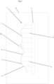
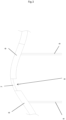
- FIG. 1 shows a perspective view at a certain point in the process, at which a certain layer of powder-like building material is solidified. At this point in time, the three-dimensional object 1 has not yet been completely produced. 2 a lateral or cross-sectional view at a specific point in time during the procedure.
- B. fender elements turbine blade elements airfoil elements act. by sequentially solidifying layers of a radiation solidifiable powder-like building material.
- the process is a laser sintering process, SLS process for short, or a laser melting process, SLM process for short.
- a support structure 2 is formed for at least partially supporting the three-dimensional object 1 to be produced by successively solidifying layers of a powder-like building material that can be solidified by means of radiation.
- a support structure 2 is also formed by successive hardening of the construction material in the same process in which the three-dimensional object 1 that is actually to be produced is also formed.
- the support structure is formed on a building board 3 of a building chamber 4 of a device (not shown in detail) for carrying out the method, i. H. in particular a device for carrying out a laser sintering process or a laser melting process.
- the support structure 2 serves to mount or support the three-dimensional object to be produced.
- the three-dimensional object 1 to be produced is built up successively on the support structure 2 .
- the support structure 2 is correspondingly adapted in its geometric shape, in particular in its cross section, to the geometric shape, in particular the cross section, of the three-dimensional object 1 to be produced (cf. 2 ).
- the support structure 2 completely reproduces the cross section of the three-dimensional object 1 to be produced in the exemplary embodiments shown in the figures.
- the support structure 2 comprises a plurality of support elements 5.
- the support elements 5 can have the same or different geometric shape, ie the same or different shape or the same or different dimensions, and be present in a regular or irregular arrangement.
- the supporting elements 5 shown in the figures are designed in the manner of webs or pillars.
- the three-dimensional object 1 which is typically formed at the same time as the support structure 2, is formed in segments. Thus, a plurality of individual or separate sub-objects 6 each forming a specific cross-sectional sub-area of the three-dimensional object 1 to be produced are formed. How out 2 results, each sub-object 6 forms a specific part of the overall cross-section of the three-dimensional object 1 .
- the three-dimensional object to be produced is therefore not built up successively over its complete cross section, but rather individual sub-objects 6 are built up successively.
- the partial objects 6 are positioned relative to one another in such a way that their arrangement results in the overall cross section of the three-dimensional object 1 .
- the particularly cross-sectional division or subdivision of the three-dimensional object 1 to be produced into individual sub-objects 6 reduces material or production-related distortion effects, since corresponding distortion effects in the sub-objects that are significantly smaller in terms of area or volume compared to the finished three-dimensional object , if at all, turn out to be significantly lower.
- the support structure 2 and the sub-objects 6 can be formed at the same time or simultaneously and thus together. Based on 2 it can be seen that a layer of powder-like building material to be solidified in a specific sub-area of the build chamber 4, here outer areas, according to the dimensions of the three-dimensional object 1 to be produced, already forms a sub-object 6 and in another part area of the build chamber 4, here inner areas, (still) no sub-object 6, but part of the supporting structure 2, ie supporting elements 5, is to be formed.
- the support structure 2 ensures that the sub-objects 6 are or will be securely arranged in their relative position to one another.
- the support structure 2 can therefore be moved or handled together with the partial objects 6 stored or supported by it without changing the position of the individual partial objects 6 relative to one another.
- the building board 3 together with the support structure 2 formed on it and the sub-objects 6 formed thereon can also be moved without changing the relative position of the individual sub-objects 6 to one another.
- connecting regions 7 are formed between the sub-objects 6 to connect the sub-objects 6 at least in sections, forming the three-dimensional object 1 .
- the sub-objects 6 are generally supported or mounted by the support structure 2 .
- Corresponding connection areas 7 can be formed by solidifying powder-like building material and/or by melting already solidified partial object sections of respective partial objects 6 that have been produced.
- the connecting areas 7 typically connect the sub-objects 6 to one another in a materially bonded manner.
- the integral connection typically takes place via welded connections, the sub-objects 6 are therefore typically welded to one another.
- connection areas 7 can in principle be formed in any desired geometric shape. In 1 Both punctiform and linear connection areas 7 are shown as examples.
- connection areas 7 can be designed to be geometrically different depending on the position of the sub-objects 6 to be connected with respect to the three-dimensional object 1 to be produced.
- the geometric shape, ie in particular the dimensions and shape, of the respective connection areas 7 can therefore depend on the position at which they are located in relation to the three-dimensional object 1 to be produced.
- connecting regions 7 which connect partial objects arranged in outer regions of the three-dimensional object 1 to one another are primarily punctiform
- connecting regions 7 which connect partial objects 6 arranged in comparatively inner regions of the three-dimensional object 1 to one another are primarily linear.
- first connect a part of the sub-objects 6 only via connecting areas 7 of a first geometric shape e.g. B. punctiform connection areas 7 to connect to realize a pre-fixing to the sub-objects 6 z. B. in a manageable state
- connecting areas 7 of a first geometric shape e.g. B. punctiform connection areas 7 to connect to realize a pre-fixing to the sub-objects 6 z. B. in a manageable state
- connection areas 7 of a second geometric shape e.g. B. punctiform connection areas 7 to connect to realize a pre-fixing to the sub-objects 6 z. B. in a manageable state
- connection areas 7 of a second geometric shape e.g. B. linear connection areas 7
- connection areas 7 of the first geometric shape can be designed to be mechanically less stable than respective connecting areas 7 of the second geometric shape.
- connection areas 7 can be formed outside or inside the device implementing the method. Consequently, the connecting regions 7 can also be formed in one and the same process in which the support structure 2 and the sub-objects 6 are also formed.
- one or more connecting regions 7 can be designed to be elastically resilient, at least in sections, in such a way that mechanical stresses caused by distortion, i. H. Tensile and / or compressive stresses, the sub-objects 6 or the complete three-dimensional object 1 are at least partially reduced.
- the connection areas 7 can also, for. B. be formed via their respective geometric shape with elastically resilient properties, via which mechanical stresses within or between the sub-objects 6 can be reduced or compensated for.
- Partial objects 6 arranged next to one another and/or one above the other are expediently connected to one another via corresponding connecting regions 7 in such a way that a slot-like gap space 8, ie a slot, is formed or remains between them.
- a slot-like gap space 8 is in 3 shown.
- the formation of slit-like gaps 8 between adjacently arranged sub-objects 6 also represents a possibility for reducing or compensating for material or production-related mechanical stresses.
- the mechanical connection of the respective sub-objects is not impaired by the formation of corresponding slit-like gaps.
- the slit-like gap spaces 8 are typically dimensioned so small, i.e. so narrow, that they can be attached to the finished object 1 are not or hardly visible.
- the slit-like gap spaces 8 have a width in a range from 1 to 100 ⁇ m, in particular in a range from 10 to 30 ⁇ m.
- the fully formed three-dimensional object 1 is removed from the support structure 2 z. B. removed manually or (partially) automatically.
- the three-dimensional object 1 can be processed or treated before the three-dimensional object 1 is removed from the support structure 2 or the building board. It is e.g. for example, it is possible for the three-dimensional object 1 arranged on the support structure 2 to be subjected to suitable post-processing processes to increase the surface quality. It is also possible to subject the three-dimensional object 1, which is still arranged on the support structure 2, to a heat treatment in order to reduce existing internal mechanical stresses. It is also possible to clean the three-dimensional object 1 that is still arranged on the support structure 2, i. H. in particular to remove building material adhering to the surface.
- the formation of the support structure 2 and / or the formation of the sub-objects 6 can also temporarily, d. H. for a certain period of time.
- One or more sub-objects 6 can be formed with a receiving space delimiting a, in particular closed, receiving volume for receiving at least one third-party object.
- a third-party object can be, for example, a z. B. act sandwich-like, lightweight element of a lightweight structure. This is particularly expedient if the three-dimensional object 1 is a wing element forming a wing or part of a wing.
Landscapes
- Engineering & Computer Science (AREA)
- Manufacturing & Machinery (AREA)
- Chemical & Material Sciences (AREA)
- Materials Engineering (AREA)
- Physics & Mathematics (AREA)
- Mechanical Engineering (AREA)
- Optics & Photonics (AREA)
- Thermal Sciences (AREA)
- Plasma & Fusion (AREA)
- Powder Metallurgy (AREA)
Description
Die Erfindung betrifft ein Verfahren zum Herstellen eines dreidimensionalen Objekts durch aufeinander folgendes Verfestigen von Schichten eines mittels Strahlung verfestigbaren pulverartigen Baumaterials.The invention relates to a method for producing a three-dimensional object by sequentially solidifying layers of a powder-like building material that can be solidified by means of radiation.
Bei derartigen Verfahren handelt es sich im Allgemeinen um generative Prozesse zur Ausbildung bzw. Herstellung dreidimensionaler Objekte bzw. Gegenstände, wie z. B. technischer Bauteile. Das Grundprinzip derartiger Verfahren sieht vor, das jeweils herzustellende dreidimensionale Objekt durch aufeinanderfolgendes bzw. sukzessives Verfestigen von Schichten eines mittels Strahlung, typischerweise Laserstrahlung, verfestigbaren pulverartigen Baumaterials auszubilden. Bekannte Beispiele solcher Verfahren sind demnach Lasersinterverfahren, kurz SLS-Verfahren, oder Laserschmelzverfahren, kurz SLM-Verfahren.Such methods are generally generative processes for the formation or manufacture of three-dimensional objects or items, such as. B. technical components. The basic principle of such methods envisages forming the three-dimensional object to be produced in each case by successive or successive solidification of layers of a powder-like building material that can be solidified by means of radiation, typically laser radiation. Known examples of such methods are therefore laser sintering methods, or SLS methods for short, or laser melting methods, SLM methods for short.
Besonders bei der Herstellung großformatiger dreidimensionaler Objekte, d. h. bei der Herstellung von Objekten mit großen Abmessungen, wie z. B. Turbinenschaufeln, Gehäusestrukturen, können material- bzw. prozessbedingt Verzugseffekte auftreten, welche eine endmaßgenaue Herstellung des herzustellenden dreidimensionalen Objekts erschweren.Especially in the production of large-scale three-dimensional objects, i. H. in the manufacture of objects with large dimensions, such as e.g. As turbine blades, housing structures, material or process-related distortion effects can occur, which make it difficult to produce the three-dimensional object to be produced with exact dimensions.
Gleichermaßen stellt die Handhabung großformatiger dreidimensionaler Objekte während bzw. nach der Herstellung regelmäßig eine Herausforderung dar.Equally, the handling of large-scale three-dimensional objects during and after production is regularly a challenge.
Der Erfindung liegt die Aufgabe zugrunde, ein verbessertes Verfahren zum Herstellen von, insbesondere großformatigen, dreidimensionalen Objekten durch aufeinander folgendes Verfestigen von Schichten eines mittels Strahlung verfestigbaren pulverartigen Baumaterials anzugeben.The invention is based on the object of specifying an improved method for producing, in particular large-format, three-dimensional objects by successively solidifying layers of a powder-like building material that can be solidified by means of radiation.
Diese Aufgabe wird durch ein Verfahren gemäß Anspruch 1 gelöst. Die Unteransprüche betreffen vorteilhafte Weiterbildungen des Verfahrens nach der Erfindung.This object is achieved by a method according to
Das erfindungsgemäße Verfahren zum Herstellen eines dreidimensionalen Objekts durch aufeinander folgendes Verfestigen von Schichten eines mittels Strahlung verfestigbaren pulverartigen Baumaterials umfasst folgende Verfahrensschritte:
Zunächst wird eine Lasersinter- oder Laserschmelzanlage mit den üblichen Komponenten vorgesehen. Diese üblichen Komponenten sind ein Gehäuse mit einer darin untergebrachten Baukammer, wobei in der Baukammer eine Tragevorrichtung zum Tragen des Objektes vorgesehen wird. Außerdem ist eine Beschichtungsvorrichtung vorhanden, um Aufbaumaterial schichtweise auf einen Träger oder auf eine vorher aufgebrachte Schicht aufzubringen. Mit einer Bestrahlungseinrichtung werden die Schichten bestrahlt und dadurch an den dem jeweiligen Querschnitt des Objektes entsprechenden Stelen verfestigt, wozu die Bestrahlungseinrichtung in der Regel einen Scanner zur Ablenkung elektromagnetischer Strahlung einer Strahlungsquelle umfasst, die in der Regel als Laser ausgebildet ist. Sodann wird eine Stützstruktur ausgebildet, dies geschieht meistens auf einer Unterlage, wie z. B. einer Bauplatte. Jedenfalls sollte die Stützstruktur in ihrem Basisbereich miteinander verbunden sein. Der Aufbau der Stützstruktur erfolgt generativ.The method according to the invention for producing a three-dimensional object by successively solidifying layers of a powder-like building material that can be solidified by means of radiation comprises the following method steps:
First, a laser sintering or laser melting system with the usual components is provided. These common components are a housing with a build chamber housed therein, with a carrying device for carrying the object being provided in the build chamber. In addition, a coating device is present in order to apply build-up material in layers onto a carrier or onto a previously applied layer. The layers are irradiated with an irradiation device and thereby solidified at the points corresponding to the respective cross section of the object, for which purpose the irradiation device usually comprises a scanner for deflecting electromagnetic radiation from a radiation source, which is usually designed as a laser. Then a support structure is formed, this is usually done on a base such. B. a building board. In any case, the support structure should be connected to one another in its base area. The support structure is built up generatively.
Verfahrensgemäß wird somit eine Stützstruktur zur zumindest abschnittsweisen Stützung des herzustellenden dreidimensionalen Objekts durch aufeinander folgendes Verfestigen von Schichten des oder eines mittels Strahlung verfestigbaren pulverartigen Baumaterials ausgebildet. Es erfolgt also neben der bzw. zusätzlich zur Ausbildung des eigentlich herzustellenden dreidimensionalen Objekts auch die Ausbildung einer Stützstruktur, deren Aufgabe und Funktion weiter unten näher erläutert wird. Wesentlich ist also, dass neben dem eigentlich herzustellenden dreidimensionalen Objekt auch die Stützstruktur durch aufeinander folgendes Verfestigen des oder eines mittels Strahlung verfestigbaren pulverartigen Baumaterials ausgebildet wird. Die Stützstruktur wird also in demselben Prozess ausgebildet, in welchem auch das eigentlich herzustellende dreidimensionale Objekt ausgebildet wird.According to the method, a support structure for at least partially supporting the three-dimensional object to be produced is thus formed by successive hardening of layers of the or a powder-like building material that can be hardened by means of radiation. Thus, in addition to or in addition to the formation of the three-dimensional object actually to be produced, a support structure is also formed, the task and function of which is explained in more detail below. It is therefore essential that, in addition to the three-dimensional object that is actually to be produced, the supporting structure is also formed by successive solidification of the or a powder-like building material that can be solidified by means of radiation. The support structure is thus formed in the same process in which the three-dimensional object actually to be produced is also formed.
Die Stützstruktur dient zur zumindest abschnittsweisen, typischerweise vollständigen, Lagerung bzw. Stützung des herzustellenden dreidimensionalen Objekts. Das herzustellende dreidimensionale Objekt wird sonach sukzessive auf der Stützstruktur aufgebaut. Die Stützstruktur ist entsprechend in ihrer geometrischen Gestalt, insbesondere in ihrem Querschnitt, an die geometrische Gestalt, insbesondere den Querschnitt, des herzustellenden dreidimensionalen Objekts anzupassen bzw. angepasst. Um die beschriebene Stützfunktion zu erfüllen, bildet die Stützstruktur den Querschnitt des herzustellenden dreidimensionalen Objekts sonach typischerweise vollständig ab.The support structure serves to store or support the three-dimensional object to be produced at least in sections, typically completely. The three-dimensional object to be produced is then built up successively on the support structure. The support structure is correspondingly to be adapted or adapted in its geometric shape, in particular in its cross section, to the geometric shape, in particular the cross section, of the three-dimensional object to be produced. In order to fulfill the support function described, the support structure therefore typically completely reproduces the cross section of the three-dimensional object to be produced.
Die Stützstruktur umfasst typischerweise wenigstens ein Stützelement, welches zur zumindest abschnittsweisen Lagerung bzw. Stützung des oder eines Teils des herzustellenden dreidimensionalen Objekts dient. In der Regel umfasst die Stützstruktur jedoch mehrere Stützelemente gleicher oder ungleicher geometrischer Gestalt, d. h. insbesondere gleicher oder ungleicher Form respektive gleicher oder ungleicher Abmessungen. Die Stützelemente können in regelmäßiger oder unregelmäßiger Anordnung vorliegen. Die Stützelemente können z. B. steg- oder stützpfeilerartig ausgebildet sein und Verzweigungen aufweisen.The support structure typically comprises at least one support element, which is used for at least partially supporting or supporting the or a part of the three-dimensional object to be produced. As a rule, however, the support structure comprises a plurality of support elements of the same or different geometric shape, i. H. in particular of the same or different shape or the same or different dimensions. The support elements can be present in a regular or irregular arrangement. The support elements can, for. B. web or pillar-like and have branches.
Die Ausbildung der Stützstruktur erfolgt typischerweise auf einer Bauplatte der Baukammer der Vorrichtung zur Durchführung des Verfahrens, d. h. insbesondere einer Vorrichtung zur Durchführung eines Lasersinterprozesses oder eines Laserschmelzprozesses.The support structure is typically formed on a building plate of the building chamber of the device for carrying out the method, ie in particular a device for carrying out a laser sintering process or a laser melting process.
Gleichzeitig bzw. simultan und somit gemeinsam mit der Ausbildung der Stützstruktur oder nach der Ausbildung der Stützstruktur wird das eigentlich herzustellende dreidimensionale Objekt ausgebildet. Wesentlich ist dabei, dass das dreidimensionale Objekt segmentiert ausgebildet wird. Es werden also mehrere, jeweils einen bestimmten Querschnittsteilbereich des herzustellenden dreidimensionalen Objekts bildende einzelne bzw. separate Teilobjekte ausgebildet, welche, wie weiter unten erläutert wird, im Weiteren unter Ausbildung des dreidimensionalen Objekts miteinander zu verbinden sind bzw. miteinander verbunden werden. Jedes Teilobjekt bildet also einen bestimmten Teil des Gesamtquerschnitts des dreidimensionalen Objekts ab. Das herzustellende dreidimensionale Objekt wird also nicht zusammenhängend über seinen vollständigen Querschnitt aufgebaut. Vielmehr werden sukzessive einzelne, jeweils einen bestimmten Teilbereich des herzustellenden dreidimensionalen Objekts bildende Teilobjekte aufgebaut. Die Teilobjekte werden positionsmäßig typischerweise derart relativ zueinander ausgebildet, dass deren Anordnung das gesamte dreidimensionale Objekt abbildet bzw. ergibt.The three-dimensional object actually to be produced is formed simultaneously or simultaneously and thus together with the formation of the support structure or after the formation of the support structure. It is essential that the three-dimensional object is formed in segments. A plurality of individual or separate sub-objects are thus formed, each forming a specific partial cross-section of the three-dimensional object to be produced, which, as explained further below, are to be connected to one another or are connected to one another to form the three-dimensional object. Each sub-object thus forms a specific part of the overall cross-section of the three-dimensional object. The three-dimensional object to be produced is therefore not built up cohesively over its entire cross section. Rather, successive individual sub-objects, each forming a specific sub-area of the three-dimensional object to be produced, are built up. In terms of position, the sub-objects are typically formed relative to one another in such a way that their arrangement depicts or results in the entire three-dimensional object.
Die oder ein Teil der Teilobjekte können mit gleicher oder ungleicher geometrischer Gestalt, d. h. insbesondere gleicher oder ungleicher Form respektive gleicher oder ungleicher Abmessungen, ausgebildet werden. Die konkrete geometrische Gestalt jeweiliger Teilobjekte hängt von den durch diese jeweils abzubildenden Teilbereichen des herzustellenden dreidimensionalen Objekts und somit von dem Gesamtquerschnitt des herzustellenden dreidimensionalen Objekts ab. Hieraus ergibt sich, dass Abmessungen, Anordnung und Orientierung entsprechender Teilobjekte in Abhängigkeit der konkreten Abmessungen des jeweils herzustellenden Objekts ausgebildet werden.The or a part of the sub-objects can have the same or different geometric shape, d. H. in particular of the same or different shape or the same or different dimensions. The specific geometric shape of the respective sub-objects depends on the sub-areas of the three-dimensional object to be produced and thus on the overall cross-section of the three-dimensional object to be produced. From this it follows that the dimensions, arrangement and orientation of corresponding sub-objects are formed as a function of the specific dimensions of the object to be produced in each case.
Durch die, insbesondere querschnittliche, Auf- bzw. Unterteilung des herzustellenden dreidimensionalen Objekts in einzelne Teilobjekte werden material- bzw. fertigungsbedingte Verzugseffekte reduziert. Dies begründet sich dadurch, dass entsprechende Verzugseffekte in den im Vergleich zu dem fertig hergestellten dreidimensionalen Objekt flächen- bzw. volumenmäßig erheblich kleineren Teilobjekten deutlich geringer ausfallen.Due to the, in particular cross-sectional, division or subdivision of the three-dimensional object to be produced into individual sub-objects, material or production-related distortion effects are reduced. This is due to the fact that the corresponding distortion effects in the sub-objects, which are significantly smaller in terms of area or volume, are significantly smaller in comparison to the finished three-dimensional object.
Aus obigen Ausführungen zu der Stützstruktur ergibt sich, dass die Teilobjekte jeweils zumindest abschnittsweise durch die Stützstruktur gestützt werden. Die Stützstruktur gewährleistet gleichermaßen, dass die Teilobjekte in ihrer relativen Position zueinander sicher angeordnet sind bzw. werden. Die Stützstruktur kann also gemeinsam mit den durch diese gelagerten bzw. gestützten Teilobjekten ohne Veränderung der Relativposition der einzelnen Teilobjekte zueinander bewegt werden, was einen erheblichen Vorteil im Hinblick auf die Handhabbarkeit des dreidimensionalen Objekts bedeutet. Selbstverständlich kann auch eine entsprechende Bauplatte samt der drauf ausgebildeten Stützstruktur und der darauf ausgebildeten Teilobjekte ohne Veränderung der Relativposition der einzelnen Teilobjekte zueinander bewegt werden.From the above statements on the support structure, it follows that the sub-objects are each supported at least in sections by the support structure. The support structure also ensures that the sub-objects are or will be securely arranged in their relative position to one another. The support structure can therefore be moved together with the sub-objects mounted or supported by it without changing the relative position of the individual sub-objects to one another, which means a considerable advantage with regard to the handling of the three-dimensional object. Of course, a corresponding building board together with the support structure formed on it and the sub-objects formed on it can also be moved without changing the relative position of the individual sub-objects to one another.
Wie erwähnt, sind die einzelnen Teilobjekte zur Ausbildung des dreidimensionalen Objekts miteinander zu verbinden. Es ist also verfahrensgemäß vorgesehen, mehrere Verbindungsbereiche zwischen den einzelnen Teilobjekten zur zumindest abschnittsweisen Verbindung der Teilobjekte unter Ausbildung des dreidimensionalen Objekts auszubilden. Während der Ausbildung jeweiliger Verbindungsbereiche sind die Teilobjekte typischerweise durch die Stützstruktur gestützt, d. h. auf dieser, insbesondere in ihrer festen Relativposition zueinander, gelagert.As mentioned, the individual sub-objects are to be connected to form the three-dimensional object. It is therefore provided according to the method to form a plurality of connection areas between the individual partial objects for the at least partial connection of the partial objects while forming the three-dimensional object. During the formation of respective connection areas, the sub-objects are typically supported by the support structure, i. H. on this, in particular in their fixed position relative to each other, stored.
Entsprechende Verbindungsbereiche können grundsätzlich in beliebiger geometrischer Gestalt ausgebildet werden. Die Verbindungsbereiche können sonach z. B. punkt- oder linienförmig oder flächig ausgebildet werden. Die Verbindungsbereiche können zumindest teilweise z.B. auch als Stege, Brücken, Dehnungsstreifen, Stäbe und dergleichen ausgebildet werden oder die Form von ineinander eingreifenden Verzahnungen oder sonstigen Formschlusselementen aufweisen. Wesentlich ist, dass die Verbindungsbereiche benachbart angeordnete Teilobjekte stabil miteinander verbinden. Typischerweise verbindet ein Verbindungsbereich dabei wenigstens zwei unmittelbar benachbart angeordnete Teilobjekte. Abmessungen, Anordnung und Orientierung entsprechender Verbindungsbereiche werden typischerweise in Abhängigkeit der konkreten Abmessungen des jeweils herzustellenden Objekts ausgebildet.Corresponding connection areas can in principle be formed in any desired geometric shape. The connection areas can thus z. B. be formed point or line or areal. At least some of the connecting areas can also be designed, for example, as webs, bridges, stretch marks, rods and the like, or have the form of interlocking teeth or other positive-locking elements. It is essential that the connection areas connect adjacently arranged sub-objects to one another in a stable manner. A connection area typically connects at least two partial objects arranged directly adjacent to one another. Dimensions, arrangement and orientation of corresponding connection areas are typically designed depending on the specific dimensions of the object to be manufactured in each case.
Nach Verbindung der Teilobjekte miteinander kann eine Wärmebehandlung erfolgen, um Spannungen in dem dann zusammenhängenden Gesamtbauteil zu reduzieren.After the sub-objects have been connected to one another, heat treatment can be carried out in order to reduce stresses in the overall component which is then connected.
In einem letzten Schritt des Verfahrens wird das vollständig ausgebildete dreidimensionale Objekt von der Stützstruktur entfernt. Das dreidimensionale Objekt kann dabei z. B. manuell oder (teil-)automatisiert von der Stützstruktur abgenommen werden. Möglich ist es selbstverständlich auch, dass die Stützstruktur manuell oder (teil-)automatisiert von dem dreidimensionalen Objekt abgenommen wird.In a final step of the method, the fully formed three-dimensional object is removed from the support structure. The three-dimensional object can z. B. be removed from the support structure manually or (partially) automatically. It is of course also possible for the support structure to be removed from the three-dimensional object manually or (partially) automatically.
Aus vorstehenden Ausführungen ergibt sich, dass die Ausbildung des eigentlich herzustellenden dreidimensionalen Objekts in wenigstens zwei Stufen erfolgt. In einer ersten Stufe werden neben der Stützstruktur die einzelnen Teilobjekte ausgebildet. Die einzelnen Teilobjekte werden durch die Stützstruktur gestützt. Die Stützung beinhaltet, wie beschrieben, gleichermaßen eine (temporäre) Sicherung der Relativposition der einzelnen Teilobjekte zueinander. In einer weiteren bzw. in einer zweiten Stufe werden die einzelnen Teilobjekte durch die Ausbildung entsprechender Verbindungsbereiche miteinander verbunden. Hierdurch wird gleichermaßen das eigentlich herzustellende dreidimensionale Objekt ausgebildet.It follows from the above statements that the three-dimensional object actually to be produced is formed in at least two stages. In a first stage, the individual sub-objects are formed in addition to the support structure. The individual sub-objects are supported by the support structure. As described, the support also includes a (temporary) securing of the relative position of the individual sub-objects to one another. In a further or in a second stage, the individual sub-objects are connected to one another by the formation of corresponding connection areas. As a result, the three-dimensional object actually to be produced is formed in the same way.
Im Rahmen des Verfahrens liegen typischerweise wenigstens zwei Datensätze vor, auf Basis welcher eine schichtweise Verfestigung des bzw. allgemein eines Baumaterials zur Ausbildung der Stützstruktur sowie der Teilobjekte bzw. des Objekts erfolgt. Ein erster Datensatz betrifft die sukzessive Ausbildung der Stützstruktur. In dem ersten Datensatz sind sonach sämtliche Daten bezüglich der Stützstruktur enthalten. Ein weiterer bzw. zweiter Datensatz betrifft die sukzessive Ausbildung des Objekts bzw. der Teilobjekte. In dem weiteren bzw. zweiten Datensatz sind sonach sämtliche Daten bezüglich des Objekts bzw. bezüglich der Teilobjekte enthalten. Der zweite Datensatz beinhaltet entsprechend insbesondere auch eine segmentierte Auf- bzw. Unterteilung des Objekts in einzelne Teilobjekte.As part of the procedure typically lie at least two data sets, on the basis of which a layer-by-layer solidification of the or generally a building material for forming the support structure and the sub-objects or the object takes place. A first data set relates to the gradual formation of the support structure. All data relating to the supporting structure are therefore contained in the first data set. A further or second data record relates to the successive formation of the object or the sub-objects. The further or second data set therefore contains all the data relating to the object or to the sub-objects. Correspondingly, the second data record also contains, in particular, a segmented division or subdivision of the object into individual sub-objects.
Im Zusammenhang mit der Ausbildung entsprechender Verbindungsbereiche ist es denkbar, dass die Verbindungsbereiche in Abhängigkeit der Position der über diese zu verbindenden Teilobjekte bezüglich des herzustellenden dreidimensionalen Objekts geometrisch unterschiedlich ausgeführt werden. Die geometrische Gestalt, d. h. insbesondere Abmessungen und Form, jeweiliger Verbindungsbereiche kann also davon abhängen, an welcher Position sich diese bezogen auf das herzustellende dreidimensionale Objekt befinden. Die geometrische Gestalt jeweiliger Verbindungsbereiche hängt insofern auch davon ab, welche konkreten Teilobjekte diese miteinander verbinden. Es ist also z. B. denkbar, dass Verbindungsbereiche, welche in äußeren Bereichen, d. h. z. B. Randbereichen des dreidimensionalen Objekts, des herzustellenden dreidimensionalen Objekts angeordnete Teilobjekte miteinander verbinden, geometrisch anders ausgeführt werden, als Verbindungsbereiche, welche in im Vergleich inneren Bereichen, d. h. z. B. im Bereich des Schwerpunkts bzw. Zentrums des dreidimensionalen Objekts, angeordnete Teilobjekte miteinander verbinden. Derart können beispielsweise lokal unterschiedliche mechanische Beanspruchungen des fertigen dreidimensionalen Objekts, insbesondere im Zusammenhang mit einer spezifischen Anwendungs- bzw. Lastsituation, berücksichtigt werden. Konkret können Verbindungsbereiche, welche in äußeren Bereichen des dreidimensionalen Objekts angeordnete Teilobjekte miteinander verbinden, z. B. punktförmig ausgebildet werden, wohingegen Verbindungsbereich, welche in im Vergleich inneren Bereichen des dreidimensionalen Objekts angeordnete Teilobjekte miteinander verbinden, z. B. linienförmig ausgebildet werden.In connection with the formation of corresponding connection areas, it is conceivable that the connection areas are implemented geometrically differently depending on the position of the sub-objects to be connected with respect to the three-dimensional object to be produced. The geometric shape, i. H. In particular, the dimensions and shape of the respective connection areas can therefore depend on the position at which they are located in relation to the three-dimensional object to be produced. In this respect, the geometric shape of the respective connection areas also depends on which specific sub-objects they connect to one another. So it is e.g. B. conceivable that connection areas, which in outer areas, d. H. e.g. B. edge areas of the three-dimensional object, the three-dimensional object to be produced arranged arranged sub-objects are executed geometrically differently than connecting areas, which in comparison inner areas, d. H. e.g. B. in the area of focus or center of the three-dimensional object, arranged sub-objects together. In this way, for example, locally different mechanical stresses on the finished three-dimensional object, in particular in connection with a specific application or load situation, can be taken into account. In concrete terms, connection areas that connect sub-objects arranged in outer areas of the three-dimensional object with one another, e.g. B. be formed point-like, whereas connection area, which connect in comparison inner areas of the three-dimensional object arranged sub-objects, z. B. be formed linearly.
Es ist auch denkbar, zunächst zumindest einen Teil der Teilobjekte nur über Verbindungsbereiche einer ersten geometrischen Gestalt, d. h. z. B. punktförmige Verbindungsbereiche, im Sinne einer Vorfixierung bzw. zur Realisierung einer solchen zu verbinden, um die Teilobjekte z. B. in einen handhabungsfähigen Zustand zu überführen, und die eigentliche Verbindung der Teilobjekte durch nachfolgend ausgebildete Verbindungsbereiche einer zweiten geometrischen Gestalt, d. h. z. B. linienförmige Verbindungsbereiche, bzw. nachfolgendes Ergänzen der Verbindungsbereiche der ersten geometrischen Gestalt, z. B. zu linienförmigen Verbindungsbereichen, auszubilden. Die Verbindungsbereiche der ersten geometrischen Gestalt können dabei mechanisch weniger stabil ausgeführt sein als jeweilige Verbindungsbereiche der zweiten geometrischen Gestalt.It is also conceivable, initially at least a part of the sub-objects only via connecting areas of a first geometric shape, i. H. e.g. B. punctiform connection areas, in the sense of a pre-fixation or for the realization of such to connect the sub-objects z. B. in a manageable state, and the actual connection of the sub-objects by subsequently formed connection areas of a second geometric shape, d. H. e.g. B. linear connection areas, or subsequent addition of the connection areas of the first geometric shape, z. B. to form linear connection areas. The connection areas of the first geometric shape can be designed to be mechanically less stable than respective connection areas of the second geometric shape.
Wie erwähnt, können die Stützstruktur und die Teilobjekte zumindest teilweise gleichzeitig bzw. simultan und somit gemeinsam ausgebildet werden. Es ist also möglich, zumindest einen Teil der Stützstruktur und zumindest einen Teil der Teilobjekte simultan bzw. gemeinsam auszubilden. Dies betrifft insbesondere Fälle, in denen über eine zu verfestigende Schicht in einem bestimmten Teilbereich der Baukammer gemäß den Abmessungen des herzustellenden dreidimensionalen Objekts bereits ein Teilobjekt auszubilden und in einem anderen Teilbereich der Baukammer entsprechend (noch) kein Teilobjekt, sondern ein Teil der Stützstruktur, d. h. z. B. ein Stützelement, auszubilden ist. Insgesamt ist es damit möglich, die Stützstruktur sowie das herzustellende dreidimensionale Objekt auf fertigungstechnisch besonders effiziente Weise auszubilden.As mentioned, the supporting structure and the sub-objects can be formed at least partially at the same time or simultaneously and thus together. It is therefore possible to form at least part of the support structure and at least part of the sub-objects simultaneously or together. This applies in particular to cases in which a sub-object is already to be formed via a layer to be solidified in a specific sub-area of the build chamber according to the dimensions of the three-dimensional object to be produced and in another sub-area of the build chamber correspondingly no sub-object (yet), but a part of the support structure, i . H. e.g. B. is a support member to form. Overall, it is thus possible to design the support structure and the three-dimensional object to be produced in a manner that is particularly efficient in terms of production technology.
Das Ausbilden der Verbindungsbereiche kann außerhalb oder innerhalb der oder allgemein einer Vorrichtung zum Herstellen eines dreidimensionalen Objekts durch aufeinander folgendes Verfestigen von Schichten eines mittels Strahlung verfestigbaren pulverartigen Baumaterials, insbesondere einer Vorrichtung zum Durchführen eines Lasersinterprozesses oder eines Laserschmelzprozesses, durchgeführt werden. Die Verbindungsbereiche können durch eine herkömmliche Schweißvorrichtung hergestellt werden, d.h. als Schweißpunkte oder Schweißraupen ausgebildet werden. Die Verbindungsbereiche können aber auch in ein und demselben Prozess, in dem auch die Stützstruktur sowie die Teilobjekte ausgebildet werden, und somit in ein und derselben Vorrichtung ausgebildet werden. Dies ist jedoch nicht zwingend, vielmehr kann die Verbindung der einzelnen Teilobjekte auch in einem anderen Prozess und somit in einer anderen Vorrichtung erfolgen. Letzteres kann beispielsweise erforderlich sein, wenn an die Verbindungsbereiche besondere Anforderungen gestellt werden, welche sich nur in einem zu dem Prozess zur Ausbildung der Stützstruktur sowie der Teilobjekte separaten Prozess zufriedenstellend realisieren lassen. In diesem Zusammenhang ist nochmals zu erwähnen, dass die einzelnen Teilobjekte durch die Stützstruktur ohne weiteres, insbesondere unter Wahrung deren Relativposition zueinander, bewegt bzw. gehandhabt werden können, um diese z. B. zwischen entsprechende Prozesse implementierenden Vorrichtungen hin und her zu bewegen.The formation of the connection areas can be carried out outside or inside or generally a device for producing a three-dimensional object by successive solidification of layers of a powder-like building material that can be solidified by means of radiation, in particular a device for carrying out a laser sintering process or a laser melting process. The connection areas can be made by conventional welding equipment, i.e. formed as spot welds or weld beads. However, the connecting regions can also be formed in one and the same process in which the supporting structure and the sub-objects are also formed, and thus in one and the same device. However, this is not mandatory, rather the connection of the individual sub-objects can also take place in a different process and thus in a different device. The latter can be necessary, for example, if special requirements are placed on the connection areas, which can only be satisfactorily implemented in a process that is separate from the process for forming the support structure and the sub-objects. In this context, it should be mentioned again that the individual sub-objects can be easily moved or handled by the support structure, in particular while maintaining their relative position to one another, in order to transport them z. B. to move back and forth between devices implementing corresponding processes.
Die Verbindungsbereiche können derart ausgebildet werden, dass sie jeweils nebeneinander und/oder übereinander angeordnet auszubildende oder ausgebildete Teilobjekte zumindest abschnittsweise miteinander verbinden. Über einen Verbindungsbereich können also grundsätzlich sowohl horizontal, d. h. in einer horizontalen Ebene, angeordnete Teilobjekte als auch vertikal, d. h. in wenigstens zwei vertikal übereinander liegenden horizontalen Ebenen, angeordnete Teilobjekte miteinander verbunden werden.The connection areas can be designed in such a way that they connect sub-objects to be or designed at least in sections to one another, arranged next to one another and/or one on top of the other. In principle, sub-objects arranged horizontally, ie in a horizontal plane, as well as sub-objects arranged vertically, ie in at least two horizontal planes lying vertically one above the other, can also be connected to one another.
Im Hinblick auf die (weitere) Reduzierung bzw. Kompensierung material- bzw. prozessbedingt auftretender mechanischer Spannungen innerhalb der Teilobjekte respektive innerhalb des dreidimensionalen Objekts kann wenigstens einen Teil der Verbindungsbereiche zumindest abschnittsweise derart elastisch federnd ausgebildet werden, dass verzugsbedingte mechanische Spannungen, d. h. Zug- und/oder Druckspannungen, der Teilobjekte und/oder des vollständigen dreidimensionalen Objekts zumindest teilweise reduziert werden. Die oder ein Teil der Verbindungsbereiche kann sonach z. B. über deren jeweilige geometrische Gestalt, d. h. insbesondere Abmessungen und Form, mit elastisch federnden Eigenschaften ausgebildet werden, über welche sich mechanische Spannungen innerhalb der oder zwischen den Teilobjekten reduzieren bzw. kompensieren lassen.With regard to the (further) reduction or compensation of material or process-related mechanical stresses occurring within the sub-objects or within the three-dimensional object, at least part of the connection areas can be designed to be elastically resilient, at least in sections, in such a way that mechanical stresses caused by distortion, i. H. Tensile and / or compressive stresses, the partial objects and / or the complete three-dimensional object are at least partially reduced. The or part of the connection areas can therefore z. B. about their respective geometric shape, d. H. in particular dimensions and shape, are designed with elastically resilient properties, via which mechanical stresses within or between the sub-objects can be reduced or compensated for.
Mit der gleichen Zielrichtung ist es möglich, dass nebeneinander und/oder übereinander angeordnete Teilobjekte derart miteinander verbunden werden, dass zwischen diesen ein schlitzartiger Spaltraum gebildet wird. Die Ausbildung schlitzartiger Spalträume, kurz Schlitze, zwischen entsprechend benachbart angeordneten Teilobjekte stellt also gleichermaßen eine Möglichkeit zur Reduzierung bzw. Kompensation material- bzw. fertigungsbedingter mechanischer Spannungen dar. Die mechanische Verbindung jeweiliger Teilobjekte wird durch die Ausbildung entsprechender schlitzartiger Spalträume nicht beeinträchtigt. Die schlitzartigen Spalträume können geometrisch so gering bemessen, d. h. so schmal, sein, dass diese am fertigen Objekt nicht oder kaum zu erkennen sind. Typischerweise weist ein entsprechend gebildeter schlitzartiger Spaltraum eine Breite in einem Bereich von 1 bis 100 µm, insbesondere in einem Bereich von 10 bis 30 µm, auf. Selbstverständlich sind Ausnahmen nach oben und unten möglich.With the same objective, it is possible for sub-objects arranged next to one another and/or one above the other to be connected to one another in such a way that a slot-like gap space is formed between them. The formation of slit-like gap spaces, slits for short, between correspondingly adjacently arranged sub-objects also represents a possibility for reducing or compensating for material or production-related mechanical stresses. The mechanical connection of the respective sub-objects is not impaired by the formation of corresponding slit-like gap spaces. The slit-like gap spaces can be dimensioned so small geometrically, i. H. be so narrow that they are hardly or not at all recognizable on the finished object. A correspondingly formed slot-like gap space typically has a width in a range from 1 to 100 μm, in particular in a range from 10 to 30 μm. Of course, exceptions above and below are possible.
Das Ausbilden entsprechender Verbindungsbereiche kann durch Verfestigen pulverartigen Baumaterials und/oder durch Aufschmelzen bereits verfestigter Teilobjektabschnitte jeweiliger hergestellter Teilobjekte erfolgen. Die Verbindungsbereiche können also aus einer auf die Teilobjekte aufgebrachten Schicht pulverartigen Baumaterials oder durch erneutes Aufschmelzen bereits verfestigter Teilobjektabschnitte ausgebildet werden.Corresponding connection areas can be formed by solidifying powder-like building material and/or by melting already solidified sub-object sections of the respective sub-objects that have been produced. The connecting areas can therefore be formed from a layer of powder-like building material applied to the partial objects or by re-melting already solidified partial object sections.
Es wurde erwähnt, dass die Teilobjekte, d. h. typischerweise benachbart angeordnete Teilobjekte, durch entsprechende Verbindungsbereiche stabil miteinander verbunden werden. Vorzugsweise werden jeweilige zu verbindende Teilobjekte durch das Ausbilden entsprechender Verbindungsbereiche dabei stoffschlüssig miteinander verbunden. Stoffschlüssige Verbindungen sind typischerweise mechanisch hoch beanspruchbar bzw. mechanisch hoch stabil.It was mentioned that the sub-objects, i. H. typically adjacent sub-objects are stably connected to one another by corresponding connection areas. Preferably, respective sub-objects to be connected are connected to one another in a materially bonded manner by the formation of corresponding connection areas. Cohesive connections are typically mechanically highly stressable or mechanically highly stable.
Jeweilige über Verbindungsbereiche zu verbindende Teilobjekte werden daher vorzugsweise miteinander verschweißt. Die Verbindungsbereiche stellen sonach vorzugsweise Schweißverbindungen dar, d. h. die Verbindungsbereiche liegen vorzugsweise als Schweißpunkte oder Schweißnähte vor bzw. umfassen solche. Die Verbindung der Teilobjekte vermittels Schweißens ist insofern praktikabel, als die im Rahmen des Verfahrens eingesetzten pulverartigen Baumaterialien typischerweise ohnehin schweißbar sind.Partial objects to be connected via connecting areas are therefore preferably welded to one another. The connection areas therefore preferably represent welded connections, i. H. the connection areas are preferably in the form of spot welds or weld seams or include such. The connection of the sub-objects by means of welding is practicable insofar as the powder-like building materials used in the process are typically weldable anyway.
Das auf der Stützstruktur angeordnete dreidimensionale Objekt kann weiter bearbeitet bzw. behandelt werden. So ist es z. B. möglich, dass das weiterhin auf der Stützstruktur angeordnete dreidimensionale Objekt geeigneten Nachbearbeitungsprozessen zur Erhöhung der Oberflächengüte unterzogen wird. Möglich ist es auch, das weiterhin auf der Bauplatte und/oder Stützstruktur angeordnete dreidimensionale Objekt einer Wärmebehandlung zu unterziehen, etwa um gegebenenfalls vorhandene innere mechanische Spannungen abzubauen. Eine Wärmebehandlung beinhaltet insbesondere ein Erwärmen des Objekts auf eine Temperatur unterhalb der Schmelztemperatur des verwendeten Baumaterials, sodass ein Abbau innerer mechanischer Spannungen erzielt wird. Möglich ist es ferner, das weiterhin auf der Stützstruktur angeordnete dreidimensionale Objekt zu reinigen, d. h. insbesondere oberflächenseitig anhaftendes Baumaterial zu entfernen. Die Aufzählung vorstehender Weiterbearbeitungsmöglichkeiten bzw. Weiterbehandlungsmöglichkeiten ist allein beispielhaft und nicht abschließend zu verstehen.The three-dimensional object arranged on the support structure can be processed or treated further. It is e.g. For example, it is possible for the three-dimensional object, which is still arranged on the support structure, to be subjected to suitable post-processing processes to increase the surface quality. It is also possible to subject the three-dimensional object, which is also arranged on the building board and/or support structure, to a heat treatment, for example in order to reduce any internal mechanical stresses that may be present. A heat treatment includes, in particular, heating the object to a temperature below the melting temperature of the construction material used, so that internal mechanical stresses are reduced. It is also possible to clean the three-dimensional object that is still arranged on the support structure, i. H. in particular to remove building material adhering to the surface. The enumeration of the above further processing options or further processing options is only exemplary and not to be understood as exhaustive.
Grundsätzlich kann das Ausbilden der Stützstruktur und/oder das Ausbilden der Teilobjekte jedoch auch zeitweise, d. h. für einen bestimmten Zeitraum, unterbrochen werden, um wenigstens eine die Eigenschaften der bis dahin ausgebildeten Stützstruktur und/oder die Eigenschaften der bis dahin ausgebildeten Teilobjekte beeinflussende Maßnahme, wie z. B. eine Wärmebehandlung, durchzuführen.In principle, however, the formation of the supporting structure and/or the formation of the sub-objects can also be carried out temporarily, ie. H. for a certain period of time, in order to take at least one measure influencing the properties of the support structure formed up to that point and/or the properties of the sub-objects formed up to that point, e.g. B. a heat treatment to perform.
Wenigstens ein Teilobjekt kann mit wenigstens einem ein, insbesondere geschlossenes, Aufnahmevolumen begrenzenden Aufnahmeraum zur Aufnahme wenigstens eines Drittgegenstands ausgebildet werden. Bei einem solchen Drittgegenstand kann es sich beispielsweise um ein, z. B. sandwichartig aufgebautes, Leichtbauelement einer Leichtbaustruktur handeln. Dies ist insbesondere zweckmäßig, wenn es sich bei dem herzustellenden bzw. hergestellten dreidimensionalen Objekt um ein eine Tragfläche oder einen Teil einer Tragfläche bildendes Tragflächenelement handelt.At least one sub-object can be formed with at least one accommodation space delimiting an, in particular closed, accommodation volume for accommodating at least one third-party object. Such a third-party object can be, for example, a z. B. act sandwich-like, lightweight element of a lightweight structure. This is particularly expedient if the three-dimensional object to be manufactured or manufactured is an airfoil element forming an airfoil or part of an airfoil.
An dieser Stelle soll nochmals hervorgehoben werden, dass sich das Verfahren insbesondere zur Herstellung vergleichsweise großformatiger dreidimensionaler Objekte, insbesondere technischer Bauteile, eignet. Als dreidimensionales Objekt kann verfahrensgemäß sonach z. B. ein Kotflügelelement oder ein Turbinenschaufelelement oder ein Tragflächenelement hergestellt werden.At this point it should be emphasized again that the method is particularly suitable for the production of comparatively large-format three-dimensional objects, in particular technical components. As a three-dimensional object, according to the method, z. B. a fender element or a turbine blade element or an airfoil element can be produced.
Im Rahmen des Verfahrens kann als pulverartiges Baumaterial sowohl Kunststoffpulver als auch Metallpulver verwendet werden. Unter einem Kunststoffpulver ist selbstverständlich auch ein Kunststoffpulvergemisch aus mehreren chemisch unterschiedlichen Kunststoffen zu verstehen. Ein Kunststoffpulver kann beispielsweise auf Polyamid oder PEEK basieren. Unter einem Metallpulver ist entsprechend selbstverständlich auch ein Metallpulvergemisch aus mehreren chemisch unterschiedlichen Metallen bzw. Metalllegierungen zu verstehen. Ein Metallpulver kann beispielsweise auf Aluminium oder auf Eisen basieren.Within the scope of the method, both plastic powder and metal powder can be used as the powder-like building material. A plastic powder is of course also to be understood as meaning a plastic powder mixture of several chemically different plastics. A plastic powder can be based on polyamide or PEEK, for example. A metal powder is of course also to be understood as meaning a metal powder mixture of a plurality of chemically different metals or metal alloys. A metal powder can be based on aluminum or iron, for example.
Die Erfindung betrifft ferner ein gemäß dem beschriebenen Verfahren hergestelltes dreidimensionales Objekt. Sämtliche Ausführungen im Zusammenhang mit dem Verfahren gelten analog für das dreidimensionale Objekt. Bei dem dreidimensionalen Objekt kann es sich z. B. um ein Kotflügelelement oder ein Turbinenschaufelelement oder ein Tragflächenelement handeln.The invention also relates to a three-dimensional object produced according to the method described. All statements in connection with the method apply analogously to the three-dimensional object. The three-dimensional object can be z. B. be a fender element or a turbine blade element or an airfoil element.
Die Erfindung ist anhand von Ausführungsbeispielen in den Zeichnungsfiguren näher erläutert. Dabei zeigen:
- Fig. 1, 2
- jeweils eine Prinzipdarstellung zur Veranschaulichung der Durchführung eines Verfahrens gemäß einem Ausführungsbeispiel der Erfindung; und
- Fig. 3
- eine vergrößerte Darstellung der in
Fig. 2 gezeigten Einzelheit III.
- Figures 1, 2
- each a schematic representation to illustrate the implementation of a method according to an embodiment of the invention; and
- 3
- an enlarged view of the in
2 shown detail III.
Die
Mit dem Verfahren lassen sich, insbesondere großformatige, dreidimensionale Objekte 1, insbesondere technische Bauteile, wie z. B. Kotflügelelemente, Turbinenschaufelelemente Tragflächenelemente, handeln. durch aufeinander folgendes Verfestigen von Schichten eines mittels Strahlung verfestigbaren pulverartigen Baumaterials herstellen. Konkret handelt es sich bei dem Verfahren um einen Lasersinterprozess, kurz SLS-Prozess, oder einen Laserschmelzprozess, kurz SLM-Prozess.With the method, in particular large-format, three-
Im Rahmen des Verfahrens wird eine Stützstruktur 2 zur zumindest abschnittsweisen Stützung des herzustellenden dreidimensionalen Objekts 1 durch aufeinander folgendes Verfestigen von Schichten eines mittels Strahlung verfestigbaren pulverartigen Baumaterials ausgebildet. Es erfolgt sonach zusätzlich zu der generativen Ausbildung des eigentlich herzustellenden dreidimensionalen Objekts 1 auch eine generative Ausbildung einer Stützstruktur 2. Auch die Stützstruktur 2 wird also durch aufeinanderfolgendes Verfestigen des Baumaterials in demselben Prozess ausgebildet, in welchem auch das eigentlich herzustellende dreidimensionale Objekt 1 ausgebildet.As part of the method, a
Die Ausbildung der Stützstruktur erfolgt auf einer Bauplatte 3 einer Baukammer 4 einer nicht näher gezeigten Vorrichtung zur Durchführung des Verfahrens, d. h. insbesondere einer Vorrichtung zur Durchführung eines Lasersinterprozesses oder eines Laserschmelzprozesses.The support structure is formed on a
Die Stützstruktur 2 dient zur Lagerung bzw. Stützung des herzustellenden dreidimensionalen Objekts. Das herzustellende dreidimensionale Objekt 1 wird sukzessive auf der Stützstruktur 2 aufgebaut. Die Stützstruktur 2 ist entsprechend in ihrer geometrischen Gestalt, insbesondere in ihrem Querschnitt, an die geometrische Gestalt, insbesondere den Querschnitt, des herzustellenden dreidimensionalen Objekts 1 angepasst (vgl.
Wie anhand von
Das typischerweise gleichzeitig mit der Stützstruktur 2 ausgebildete dreidimensionale Objekt 1 wird segmentiert ausgebildet. Es werden also mehrere, jeweils einen bestimmten Querschnittsteilbereich des herzustellenden dreidimensionalen Objekts 1 bildende einzelne bzw. separate Teilobjekte 6 ausgebildet. Wie sich aus
Durch die, insbesondere querschnittliche, Auf- bzw. Unterteilung des herzustellenden dreidimensionalen Objekts 1 in einzelne Teilobjekte 6 werden material- bzw. fertigungsbedingte Verzugseffekte reduziert, da entsprechende Verzugseffekte in den im Vergleich zu dem fertig hergestellten dreidimensionalen Objekt flächen- bzw. volumenmäßig erheblich kleineren Teilobjekten, wenn überhaupt, deutlich geringer ausfallen.The particularly cross-sectional division or subdivision of the three-
Die Stützstruktur 2 und die Teilobjekte 6 können, wie erwähnt, gleichzeitig bzw. simultan und somit gemeinsam ausgebildet werden. Anhand von
Die Stützstruktur 2 gewährleistet, dass die Teilobjekte 6 in ihrer relativen Position zueinander sicher angeordnet sind bzw. werden. Die Stützstruktur 2 kann also gemeinsam mit den durch diese gelagerten bzw. gestützten Teilobjekten 6 ohne Veränderung der Relativposition der einzelnen Teilobjekte 6 zueinander bewegt bzw. gehandhabt werden. Selbstverständlich kann auch die Bauplatte 3 samt der drauf ausgebildeten Stützstruktur 2 und der darauf ausgebildeten Teilobjekte 6 ohne Veränderung der Relativposition der einzelnen Teilobjekte 6 zueinander bewegt werden.The
Zur Verbindung der Teilobjekte 6 werden Verbindungsbereiche 7 zwischen den Teilobjekten 6 zur zumindest abschnittsweisen Verbindung der Teilobjekte 6 unter Ausbildung des dreidimensionalen Objekts 1 ausgebildet. Während der Ausbildung der in den Fig. mit verstärkter Strichlinie dargestellten Verbindungsbereiche 7 sind die Teilobjekte 6 in der Regel durch die Stützstruktur 2 gestützt bzw. gelagert. Das Ausbilden entsprechender Verbindungsbereiche 7 kann durch Verfestigen pulverartigen Baumaterials und/oder durch Aufschmelzen bereits verfestigter Teilobjektabschnitte jeweiliger hergestellter Teilobjekte 6 erfolgen.To connect the
Die Verbindungsbereiche 7 verbinden die Teilobjekte 6 typischerweise stoffschlüssig miteinander. Die stoffschlüssige Verbindung erfolgt typischerweise über Schweißverbindungen, die Teilobjekte 6 werden daher typischerweise miteinander verschweißt.The connecting
Entsprechende Verbindungsbereiche 7 können grundsätzlich in beliebiger geometrischer Gestalt ausgebildet werden. In
Entsprechende Verbindungsbereiche 7 können in Abhängigkeit der Position der über diese zu verbindenden Teilobjekte 6 bezüglich des herzustellenden dreidimensionalen Objekts 1 geometrisch unterschiedlich ausgeführt werden. Die geometrische Gestalt, d. h. insbesondere Abmessungen und Form, jeweiliger Verbindungsbereiche 7 kann also davon abhängen, an welcher Position sich diese bezogen auf das herzustellende dreidimensionale Objekt 1 befinden. In
Es ist auch denkbar, zunächst einen Teil der Teilobjekte 6 nur über Verbindungsbereiche 7 einer ersten geometrischen Gestalt, z. B. punktförmige Verbindungsbereiche 7, zur Realisierung einer Vorfixierung zu verbinden, um die Teilobjekte 6 z. B. in einen handhabungsfähigen Zustand zu überführen, und die eigentliche Verbindung der Teilobjekte 6 durch nachfolgend ausgebildete Verbindungsbereiche 7 einer zweiten geometrischen Gestalt, z. B. linienförmige Verbindungsbereiche 7, bzw. nachfolgendes Ergänzen der Verbindungsbereiche 7 der ersten geometrischen Gestalt , z. B. zu linienförmigen Verbindungsbereichen, auszubilden. Jeweilige Verbindungsbereiche 7 der ersten geometrischen Gestalt können mechanisch weniger stabil ausgeführt sein als jeweilige Verbindungsbereiche 7 der zweiten geometrischen Gestalt.It is also conceivable to first connect a part of the
Das Ausbilden entsprechender Verbindungsbereiche 7 kann außerhalb oder innerhalb der das Verfahren implementierenden Vorrichtung durchgeführt werden. Mithin können auch die Verbindungsbereiche 7 in ein und demselben Prozess, in dem auch die Stützstruktur 2 sowie die Teilobjekte 6 ausgebildet werden, ausgebildet werden.Corresponding
Im Hinblick auf die (weitere) Reduzierung bzw. Kompensierung material- bzw. prozessbedingt auftretender mechanischer Spannungen innerhalb der Teilobjekte respektive innerhalb des dreidimensionalen Objekts können einzelne oder mehrere Verbindungsbereiche 7 zumindest abschnittsweise derart elastisch federnd ausgebildet werden, dass verzugsbedingte mechanische Spannungen, d. h. Zug- und/oder Druckspannungen, der Teilobjekte 6 bzw. des vollständigen dreidimensionalen Objekts 1 zumindest teilweise reduziert werden. Die Verbindungsbereiche 7 können also, z. B. über deren jeweilige geometrische Gestalt mit elastisch federnden Eigenschaften ausgebildet werden, über welche sich mechanische Spannungen innerhalb der oder zwischen den Teilobjekten 6 reduzieren bzw. kompensieren lassen.With regard to the (further) reduction or compensation of material or process-related mechanical stresses occurring within the sub-objects or within the three-dimensional object, one or more connecting
Zweckmäßig werden nebeneinander und/oder übereinander angeordnete Teilobjekte 6 über entsprechende Verbindungsbereiche 7 derart miteinander verbunden, dass zwischen diesen ein schlitzartiger Spaltraum 8, d. h. ein Schlitz, gebildet wird bzw. verbleibt. Ein solcher schlitzartiger Spaltraum 8 ist in
In einem letzten Schritt des Verfahrens wird das vollständig ausgebildete dreidimensionale Objekt 1 von der Stützstruktur 2 z. B. manuell oder (teil-) automatisiert entfernt.In a final step of the method, the fully formed three-
Vor der Entfernung des dreidimensionalen Objekts 1 von der Stützstruktur 2 bzw. der Bauplatte kann das dreidimensionale Objekt 1 jedoch bearbeitet bzw. behandelt werden. So ist es z. B. möglich, dass das auf der Stützstruktur 2 angeordnete dreidimensionale Objekt 1 geeigneten Nachbearbeitungsprozessen zur Erhöhung der Oberflächengüte unterzogen wird. Möglich ist es auch, das weiterhin auf der Stützstruktur 2 angeordnete dreidimensionale Objekt 1 einer Wärmebehandlung zu unterziehen, um vorhandene innere mechanische Spannungen abzubauen. Möglich ist es ferner, das weiterhin auf der Stützstruktur 2 angeordnete dreidimensionale Objekt 1 zu reinigen, d. h. insbesondere oberflächenseitig anhaftendes Baumaterial zu entfernen.However, before the three-
Um wenigstens eine die Eigenschaften der bis dahin ausgebildeten Stützstruktur 2 und/oder die Eigenschaften der bis dahin ausgebildeten Teilobjekte 6 beeinflussende Maßnahme, d. h. z. B. eine Wärmebehandlung, durchzuführen, kann das Ausbilden der Stützstruktur 2 und/oder das Ausbilden der Teilobjekte 6 auch zeitweise, d. h. für einen bestimmten Zeitraum, unterbrochen werden.In order to take at least one measure influencing the properties of the
Ein oder mehrere Teilobjekte 6 können mit einem ein, insbesondere geschlossenes, Aufnahmevolumen begrenzenden Aufnahmeraum zur Aufnahme wenigstens eines Drittgegenstands ausgebildet werden. Bei einem solchen Drittgegenstand kann es sich beispielsweise um ein, z. B. sandwichartig aufgebautes, Leichtbauelement einer Leichtbaustruktur handeln. Dies ist insbesondere zweckmäßig, wenn es sich bei dem dreidimensionalen Objekt 1 um ein eine Tragfläche oder einen Teil einer Tragfläche bildendes Tragflächenelement handelt.One or more sub-objects 6 can be formed with a receiving space delimiting a, in particular closed, receiving volume for receiving at least one third-party object. Such a third-party object can be, for example, a z. B. act sandwich-like, lightweight element of a lightweight structure. This is particularly expedient if the three-
- 11
- Objektobject
- 22
- Stützstruktursupport structure
- 33
- Bauplattebuild plate
- 44
- Baukammerbuild chamber
- 55
- Stützelementsupport element
- 66
- Teilobjektsub-object
- 77
- Verbindungsbereichconnection area
- 88th
- Spaltraumgap space
Claims (14)
- A method for producing a three-dimensional object (1) by successive solidification of layers of a powder-like build material that is solidifiable by radiation, having the following method steps:- providing a laser sintering unit or laser melting unit having a housing, a build chamber situated therein, a coating device for applying build material in layers, an irradiation device for irradiating the applied layers of the build material, and a group structure onto which the object and/or a support structure for the object are/is generatively built up,- forming the support structure (2) for supporting, at least in part, the three-dimensional object (1) to be produced, by successive solidification of layers of the build material,- forming multiple individual partial objects (6), each of which forms a certain partial area of the three-dimensional object (1) to be produced, by successive solidification of layers of the build material, wherein at least one partial object (6) is formed, at least in part, on the support structure (2), wherein the partial objects each form a determined part of the cross-section of the three-dimensional object (1) to be manufactured and are, in the following, under formation of the three-dimensional object (1) to be connected with each other and are connected with each other, wherein through the division or subdivision of the three-dimensional object (1) to be manufactured into individual partial objects (6), deformation effects related to material or production can be reduced,- forming connecting areas (7) between the partial objects (6) for connecting, at least in part, the partial objects (6) to form the three-dimensional object,- removing the three-dimensional object (1) from the support structure (2) after the connecting areas (7) are formed.
- The method according to Claim 1, wherein at least a portion of the support structure (2) and at least a portion of at least one partial object (6) are formed simultaneously.
- The method according to Claim 1 or 2, wherein the formation of the connecting areas (7) is carried out outside or inside the SLS unit or LSM unit.
- The method according to one of the preceding claims, wherein the connecting areas (7) are designed in such a way that in each case they connect, at least in part, partial objects (6) that are formed or that are to be formed next to one another and/or on top of one another.
- The method according to one of the preceding claims, wherein the connecting areas (7) have different geometric designs with respect to the three-dimensional object (1) to be produced, depending on the position of the partial objects (6) to be connected via the connecting areas.
- The method according to one of the preceding claims, wherein at least a portion of the partial objects (6) are first connected via connecting areas (7) of a first, in particular punctiform, geometric shape in order to convert the partial objects (6) connected to one another in this way into a handleable state, and subsequently, connecting areas (7) of a second, in particular linear, geometric shape are formed, and/or subsequently, already formed connecting areas (7) of the first geometric shape are supplemented to form in particular linear connecting areas (7) of the second geometric shape.
- The method according to one of the preceding claims, wherein at least a portion of the connecting areas (7), at least in part, have an elastically resilient design such that mechanical stresses on the partial objects (6) and/or the object (1) caused by warping are reduced.
- The method according to one of the preceding claims, wherein partial objects (6) situated next to one another and/or on top of one another are joined together in such a way that a slot-like gap (8) is formed between them.
- The method according to one of the preceding claims, wherein the formation of corresponding connecting areas (7) takes place by solidification of powder-like build material and/or by melting of already solidified partial object portions of already produced partial objects (6).
- The method according to one of the preceding claims, wherein particular partial objects (6) to be connected are integrally joined together by forming corresponding connecting areas (7).
- The method according to Claim 10, wherein the particular partial objects (6) to be connected are welded together.
- The method according to one of the preceding claims, wherein the formation of the support structure (2) and/or the formation of the partial objects (6) are/is temporarily interrupted in order to carry out at least one measure, in particular heat treatment, that influences the properties of the support structure (2) formed up to that point and/or the properties of the partial objects (6) formed up to that point.
- The method according to one of the preceding claims, wherein at least two of the particular partial objects (6) are formed with the same or different geometric shapes.
- The method according to one of the preceding claims, wherein at least one partial object (6) having at least one receiving space that delimits an in particular closed receiving volume is designed for accommodating at least one third object.
Priority Applications (1)
| Application Number | Priority Date | Filing Date | Title |
|---|---|---|---|
| EP19177090.8A EP3552804B1 (en) | 2014-08-22 | 2015-08-18 | Method for producing a three-dimensional object |
Applications Claiming Priority (2)
| Application Number | Priority Date | Filing Date | Title |
|---|---|---|---|
| DE102014012425.8A DE102014012425B4 (en) | 2014-08-22 | 2014-08-22 | Method for producing a three-dimensional object |
| PCT/EP2015/068938 WO2016026852A1 (en) | 2014-08-22 | 2015-08-18 | Method for producing a three-dimensional object |
Related Child Applications (2)
| Application Number | Title | Priority Date | Filing Date |
|---|---|---|---|
| EP19177090.8A Division EP3552804B1 (en) | 2014-08-22 | 2015-08-18 | Method for producing a three-dimensional object |
| EP19177090.8A Division-Into EP3552804B1 (en) | 2014-08-22 | 2015-08-18 | Method for producing a three-dimensional object |
Publications (3)
| Publication Number | Publication Date |
|---|---|
| EP3183083A1 EP3183083A1 (en) | 2017-06-28 |
| EP3183083B1 EP3183083B1 (en) | 2019-07-03 |
| EP3183083B2 true EP3183083B2 (en) | 2023-02-08 |
Family
ID=53900814
Family Applications (2)
| Application Number | Title | Priority Date | Filing Date |
|---|---|---|---|
| EP19177090.8A Active EP3552804B1 (en) | 2014-08-22 | 2015-08-18 | Method for producing a three-dimensional object |
| EP15753354.8A Active EP3183083B2 (en) | 2014-08-22 | 2015-08-18 | Method for producing a three-dimensional object |
Family Applications Before (1)
| Application Number | Title | Priority Date | Filing Date |
|---|---|---|---|
| EP19177090.8A Active EP3552804B1 (en) | 2014-08-22 | 2015-08-18 | Method for producing a three-dimensional object |
Country Status (5)
| Country | Link |
|---|---|
| US (1) | US20170274455A1 (en) |
| EP (2) | EP3552804B1 (en) |
| CN (1) | CN107073821B (en) |
| DE (1) | DE102014012425B4 (en) |
| WO (1) | WO2016026852A1 (en) |
Families Citing this family (23)
| Publication number | Priority date | Publication date | Assignee | Title |
|---|---|---|---|---|
| CN108436082A (en) | 2014-06-20 | 2018-08-24 | 维洛3D公司 | Equipment, system and method for 3 D-printing |
| DE102015115821A1 (en) * | 2015-09-18 | 2017-03-23 | Dyemansion Gmbh | Process for the manufacture and surface treatment of a molded part |
| US10065270B2 (en) | 2015-11-06 | 2018-09-04 | Velo3D, Inc. | Three-dimensional printing in real time |
| US10286603B2 (en) | 2015-12-10 | 2019-05-14 | Velo3D, Inc. | Skillful three-dimensional printing |
| US10434573B2 (en) | 2016-02-18 | 2019-10-08 | Velo3D, Inc. | Accurate three-dimensional printing |
| US11691343B2 (en) | 2016-06-29 | 2023-07-04 | Velo3D, Inc. | Three-dimensional printing and three-dimensional printers |
| US10286452B2 (en) | 2016-06-29 | 2019-05-14 | Velo3D, Inc. | Three-dimensional printing and three-dimensional printers |
| US20180095450A1 (en) | 2016-09-30 | 2018-04-05 | Velo3D, Inc. | Three-dimensional objects and their formation |
| WO2018128695A2 (en) | 2016-11-07 | 2018-07-12 | Velo3D, Inc. | Gas flow in three-dimensional printing |
| US20180186080A1 (en) | 2017-01-05 | 2018-07-05 | Velo3D, Inc. | Optics in three-dimensional printing |
| CN106623933A (en) * | 2017-01-20 | 2017-05-10 | 北京航信增材科技有限公司 | Manufacturing method for shape follow-up supporting model for selective laser melting metal additive manufacturing |
| US10888925B2 (en) | 2017-03-02 | 2021-01-12 | Velo3D, Inc. | Three-dimensional printing of three-dimensional objects |
| WO2018183396A1 (en) | 2017-03-28 | 2018-10-04 | Velo3D, Inc. | Material manipulation in three-dimensional printing |
| JP6898187B2 (en) * | 2017-04-27 | 2021-07-07 | 株式会社神戸製鋼所 | Joining method and structure of laminated molding parts, and laminated molding parts |
| DE102017208520A1 (en) * | 2017-05-19 | 2018-11-22 | Premium Aerotec Gmbh | Method for producing an object by means of generative manufacturing, component, in particular for an aircraft or spacecraft, and computer-readable medium |
| DE102017223503A1 (en) | 2017-12-21 | 2019-06-27 | Volkswagen Aktiengesellschaft | Method for the additive production of a metallic component provided with a support structure (I) |
| DE102017223506A1 (en) | 2017-12-21 | 2019-06-27 | Volkswagen Aktiengesellschaft | Method for the additive production of a metallic component (II) provided with a supporting structure |
| US10272525B1 (en) | 2017-12-27 | 2019-04-30 | Velo3D, Inc. | Three-dimensional printing systems and methods of their use |
| US10144176B1 (en) | 2018-01-15 | 2018-12-04 | Velo3D, Inc. | Three-dimensional printing systems and methods of their use |
| CN110962346A (en) * | 2018-09-28 | 2020-04-07 | 安世亚太科技股份有限公司 | Plane distortion compensation method for additive substrate |
| KR20220031745A (en) | 2019-07-26 | 2022-03-11 | 벨로3디, 인크. | Quality assurance for 3D object shaping |
| CN111451503B (en) * | 2020-04-10 | 2022-08-12 | 哈尔滨福沃德多维智能装备有限公司 | SLM additive manufacturing fine part printing support adding method and removing method |
| DE102022100702A1 (en) | 2022-01-13 | 2023-07-13 | Amsis Gmbh | Process for the additive manufacturing of at least one three-dimensional object |
Family Cites Families (13)
| Publication number | Priority date | Publication date | Assignee | Title |
|---|---|---|---|---|
| CN1120773C (en) * | 2000-12-15 | 2003-09-10 | 清华大学 | Presplit fast prototype making process |
| DE10219983B4 (en) | 2002-05-03 | 2004-03-18 | Bego Medical Ag | Process for manufacturing products using free-form laser sintering |
| US7329379B2 (en) * | 2003-11-04 | 2008-02-12 | Hewlett-Packard Development Company, Lp. | Method for solid freeform fabrication of a three-dimensional object |
| DE102004032559B4 (en) | 2004-07-06 | 2006-06-01 | Dr.Ing.H.C. F. Porsche Ag | Method for fixing and producing components, in particular vehicle components |
| DE102005015870B3 (en) * | 2005-04-06 | 2006-10-26 | Eos Gmbh Electro Optical Systems | Device and method for producing a three-dimensional object |
| US7509725B2 (en) * | 2005-04-22 | 2009-03-31 | The Boeing Company | Design methodology to maximize the application of direct manufactured aerospace parts |
| DE102006056160A1 (en) | 2005-11-30 | 2007-05-31 | Fockele, Matthias, Dr. | Bending tool body for producing complex workpieces has a least one segmented regions with column segments against each other separated by narrow gaps |
| GB0715621D0 (en) | 2007-08-10 | 2007-09-19 | Rolls Royce Plc | Support architecture |
| FR2954200B1 (en) * | 2009-12-23 | 2012-03-02 | Snecma | PROCESS FOR MAKING A TURBOMACHINE METAL TURBINE REINFORCEMENT |
| US8727729B2 (en) | 2010-06-29 | 2014-05-20 | Turbocam, Inc. | Method for producing a shrouded impeller from two or more components |
| DE102010041461B4 (en) | 2010-09-27 | 2016-03-17 | Siemens Aktiengesellschaft | Test method for an additive manufacturing process |
| JP6280102B2 (en) * | 2012-05-10 | 2018-02-14 | レニショウ パブリック リミテッド カンパニーRenishaw Public Limited Company | Method for manufacturing an article |
| TWI548535B (en) * | 2013-11-18 | 2016-09-11 | 三緯國際立體列印科技股份有限公司 | Method of three-dimensional printing |
-
2014
- 2014-08-22 DE DE102014012425.8A patent/DE102014012425B4/en active Active
-
2015
- 2015-08-18 CN CN201580057391.3A patent/CN107073821B/en active Active
- 2015-08-18 EP EP19177090.8A patent/EP3552804B1/en active Active
- 2015-08-18 WO PCT/EP2015/068938 patent/WO2016026852A1/en active Application Filing
- 2015-08-18 EP EP15753354.8A patent/EP3183083B2/en active Active
- 2015-08-18 US US15/505,842 patent/US20170274455A1/en not_active Abandoned
Also Published As
| Publication number | Publication date |
|---|---|
| EP3552804B1 (en) | 2024-03-13 |
| CN107073821A (en) | 2017-08-18 |
| EP3183083B1 (en) | 2019-07-03 |
| EP3552804A1 (en) | 2019-10-16 |
| DE102014012425B4 (en) | 2024-06-06 |
| DE102014012425A1 (en) | 2016-03-17 |
| CN107073821B (en) | 2020-03-10 |
| WO2016026852A1 (en) | 2016-02-25 |
| EP3183083A1 (en) | 2017-06-28 |
| US20170274455A1 (en) | 2017-09-28 |
Similar Documents
| Publication | Publication Date | Title |
|---|---|---|
| EP3183083B2 (en) | Method for producing a three-dimensional object | |
| EP2782705B2 (en) | Method of generative producing a component using a laser beam before, during and after the assembly | |
| EP2857139B1 (en) | Device for laser processing materials with a laser head movable along a space direction | |
| WO2014202413A2 (en) | Device and method for additively producing at least one component region of a component | |
| EP2913124A2 (en) | Production of residual compressive stresses in generative production | |
| DE102014212100A1 (en) | Generative production process and device for this purpose with oppositely directed inert gas streams | |
| EP2384882A1 (en) | Method for generative creation of a three dimensional object with spatial elements and method for producing a corresponding data set | |
| EP3621758B1 (en) | Method for a component with a predetermined surface structure to be produced by additive manufacturing | |
| WO2011050790A2 (en) | Method and device for producing a component of a turbomachine | |
| EP3520929A1 (en) | Method for selectively irradiating a material layer, manufacturing method and computer program product | |
| EP3248719B1 (en) | Method and apparatus for additive manufacture of at least one component area of a component | |
| DE102014108081A1 (en) | Device and method for the generative production of at least one component region of a component | |
| EP3321011B1 (en) | Method for improving the surface quality of components made by additive manufacturing | |
| EP3338918A1 (en) | Layered construction device and layered construction method for additive manufacture of at least one component area of a component | |
| DE102016209618A1 (en) | Method and device for the additive production of at least one component region of a component | |
| EP3956088A1 (en) | Layer building process and layer building apparatus for the additive manufacture of at least one wall of a component, as well as computer program product and storage medium | |
| DE102016211068A1 (en) | Method for producing at least one component | |
| EP3175941B1 (en) | Method and apparatus for additive manufacture of at least one component area of a component | |
| WO2021074188A1 (en) | Method for operating a device for the additive manufacture of a three-dimensional object and method for creating a process window for carrying out said method | |
| DE102020209464A1 (en) | Layer building method and layer building device for the additive manufacturing of a component, component and computer program product | |
| WO2017194275A1 (en) | Construction platform for additive manufacturing, and method | |
| DE102018212343A1 (en) | Process for building up a component in layers | |
| WO2021008640A1 (en) | Layer construction method and layer construction device for additively manufacturing at least one component region of a component, and computer program product and storage medium | |
| DE102020209470A1 (en) | Method for determining individual vectors for controlling and/or regulating at least one energy beam of a layer construction device and layer construction device |
Legal Events
| Date | Code | Title | Description |
|---|---|---|---|
| STAA | Information on the status of an ep patent application or granted ep patent |
Free format text: STATUS: THE INTERNATIONAL PUBLICATION HAS BEEN MADE |
|
| PUAI | Public reference made under article 153(3) epc to a published international application that has entered the european phase |
Free format text: ORIGINAL CODE: 0009012 |
|
| STAA | Information on the status of an ep patent application or granted ep patent |
Free format text: STATUS: REQUEST FOR EXAMINATION WAS MADE |
|
| 17P | Request for examination filed |
Effective date: 20170308 |
|
| AK | Designated contracting states |
Kind code of ref document: A1 Designated state(s): AL AT BE BG CH CY CZ DE DK EE ES FI FR GB GR HR HU IE IS IT LI LT LU LV MC MK MT NL NO PL PT RO RS SE SI SK SM TR |
|
| AX | Request for extension of the european patent |
Extension state: BA ME |
|
| DAV | Request for validation of the european patent (deleted) | ||
| DAX | Request for extension of the european patent (deleted) | ||
| STAA | Information on the status of an ep patent application or granted ep patent |
Free format text: STATUS: EXAMINATION IS IN PROGRESS |
|
| 17Q | First examination report despatched |
Effective date: 20181116 |
|
| REG | Reference to a national code |
Ref country code: DE Ref legal event code: R079 Ref document number: 502015009534 Country of ref document: DE Free format text: PREVIOUS MAIN CLASS: B22F0003105000 Ipc: B29C0064153000 |
|
| GRAP | Despatch of communication of intention to grant a patent |
Free format text: ORIGINAL CODE: EPIDOSNIGR1 |
|
| STAA | Information on the status of an ep patent application or granted ep patent |
Free format text: STATUS: GRANT OF PATENT IS INTENDED |
|
| INTG | Intention to grant announced |
Effective date: 20190201 |
|
| RIC1 | Information provided on ipc code assigned before grant |
Ipc: B22F 3/24 20060101ALI20190118BHEP Ipc: B22F 5/04 20060101ALN20190118BHEP Ipc: B29C 64/153 20170101AFI20190118BHEP Ipc: B33Y 10/00 20150101ALN20190118BHEP Ipc: B22F 3/105 20060101ALI20190118BHEP Ipc: B29C 64/40 20170101ALI20190118BHEP |
|
| GRAS | Grant fee paid |
Free format text: ORIGINAL CODE: EPIDOSNIGR3 |
|
| GRAA | (expected) grant |
Free format text: ORIGINAL CODE: 0009210 |
|
| STAA | Information on the status of an ep patent application or granted ep patent |
Free format text: STATUS: THE PATENT HAS BEEN GRANTED |
|
| AK | Designated contracting states |
Kind code of ref document: B1 Designated state(s): AL AT BE BG CH CY CZ DE DK EE ES FI FR GB GR HR HU IE IS IT LI LT LU LV MC MK MT NL NO PL PT RO RS SE SI SK SM TR |
|
| REG | Reference to a national code |
Ref country code: GB Ref legal event code: FG4D Free format text: NOT ENGLISH |
|
| REG | Reference to a national code |
Ref country code: CH Ref legal event code: EP Ref country code: AT Ref legal event code: REF Ref document number: 1150447 Country of ref document: AT Kind code of ref document: T Effective date: 20190715 |
|
| REG | Reference to a national code |
Ref country code: DE Ref legal event code: R096 Ref document number: 502015009534 Country of ref document: DE |
|
| REG | Reference to a national code |
Ref country code: IE Ref legal event code: FG4D Free format text: LANGUAGE OF EP DOCUMENT: GERMAN |
|
| REG | Reference to a national code |
Ref country code: NL Ref legal event code: MP Effective date: 20190703 |
|
| REG | Reference to a national code |
Ref country code: LT Ref legal event code: MG4D |
|
| PG25 | Lapsed in a contracting state [announced via postgrant information from national office to epo] |
Ref country code: LT Free format text: LAPSE BECAUSE OF FAILURE TO SUBMIT A TRANSLATION OF THE DESCRIPTION OR TO PAY THE FEE WITHIN THE PRESCRIBED TIME-LIMIT Effective date: 20190703 Ref country code: FI Free format text: LAPSE BECAUSE OF FAILURE TO SUBMIT A TRANSLATION OF THE DESCRIPTION OR TO PAY THE FEE WITHIN THE PRESCRIBED TIME-LIMIT Effective date: 20190703 Ref country code: PT Free format text: LAPSE BECAUSE OF FAILURE TO SUBMIT A TRANSLATION OF THE DESCRIPTION OR TO PAY THE FEE WITHIN THE PRESCRIBED TIME-LIMIT Effective date: 20191104 Ref country code: NL Free format text: LAPSE BECAUSE OF FAILURE TO SUBMIT A TRANSLATION OF THE DESCRIPTION OR TO PAY THE FEE WITHIN THE PRESCRIBED TIME-LIMIT Effective date: 20190703 Ref country code: BG Free format text: LAPSE BECAUSE OF FAILURE TO SUBMIT A TRANSLATION OF THE DESCRIPTION OR TO PAY THE FEE WITHIN THE PRESCRIBED TIME-LIMIT Effective date: 20191003 Ref country code: NO Free format text: LAPSE BECAUSE OF FAILURE TO SUBMIT A TRANSLATION OF THE DESCRIPTION OR TO PAY THE FEE WITHIN THE PRESCRIBED TIME-LIMIT Effective date: 20191003 Ref country code: CZ Free format text: LAPSE BECAUSE OF FAILURE TO SUBMIT A TRANSLATION OF THE DESCRIPTION OR TO PAY THE FEE WITHIN THE PRESCRIBED TIME-LIMIT Effective date: 20190703 Ref country code: SE Free format text: LAPSE BECAUSE OF FAILURE TO SUBMIT A TRANSLATION OF THE DESCRIPTION OR TO PAY THE FEE WITHIN THE PRESCRIBED TIME-LIMIT Effective date: 20190703 Ref country code: HR Free format text: LAPSE BECAUSE OF FAILURE TO SUBMIT A TRANSLATION OF THE DESCRIPTION OR TO PAY THE FEE WITHIN THE PRESCRIBED TIME-LIMIT Effective date: 20190703 |
|
| REG | Reference to a national code |
Ref country code: DE Ref legal event code: R026 Ref document number: 502015009534 Country of ref document: DE |
|
| PG25 | Lapsed in a contracting state [announced via postgrant information from national office to epo] |
Ref country code: IS Free format text: LAPSE BECAUSE OF FAILURE TO SUBMIT A TRANSLATION OF THE DESCRIPTION OR TO PAY THE FEE WITHIN THE PRESCRIBED TIME-LIMIT Effective date: 20191103 Ref country code: GR Free format text: LAPSE BECAUSE OF FAILURE TO SUBMIT A TRANSLATION OF THE DESCRIPTION OR TO PAY THE FEE WITHIN THE PRESCRIBED TIME-LIMIT Effective date: 20191004 Ref country code: LV Free format text: LAPSE BECAUSE OF FAILURE TO SUBMIT A TRANSLATION OF THE DESCRIPTION OR TO PAY THE FEE WITHIN THE PRESCRIBED TIME-LIMIT Effective date: 20190703 Ref country code: RS Free format text: LAPSE BECAUSE OF FAILURE TO SUBMIT A TRANSLATION OF THE DESCRIPTION OR TO PAY THE FEE WITHIN THE PRESCRIBED TIME-LIMIT Effective date: 20190703 Ref country code: AL Free format text: LAPSE BECAUSE OF FAILURE TO SUBMIT A TRANSLATION OF THE DESCRIPTION OR TO PAY THE FEE WITHIN THE PRESCRIBED TIME-LIMIT Effective date: 20190703 Ref country code: ES Free format text: LAPSE BECAUSE OF FAILURE TO SUBMIT A TRANSLATION OF THE DESCRIPTION OR TO PAY THE FEE WITHIN THE PRESCRIBED TIME-LIMIT Effective date: 20190703 |
|
| PLBI | Opposition filed |
Free format text: ORIGINAL CODE: 0009260 |
|
| PG25 | Lapsed in a contracting state [announced via postgrant information from national office to epo] |
Ref country code: TR Free format text: LAPSE BECAUSE OF FAILURE TO SUBMIT A TRANSLATION OF THE DESCRIPTION OR TO PAY THE FEE WITHIN THE PRESCRIBED TIME-LIMIT Effective date: 20190703 |
|
| 26 | Opposition filed |
Opponent name: SIEMENS GAS AND POWER GMBH & CO. KG Effective date: 20200218 |
|
| PG25 | Lapsed in a contracting state [announced via postgrant information from national office to epo] |
Ref country code: DK Free format text: LAPSE BECAUSE OF FAILURE TO SUBMIT A TRANSLATION OF THE DESCRIPTION OR TO PAY THE FEE WITHIN THE PRESCRIBED TIME-LIMIT Effective date: 20190703 Ref country code: EE Free format text: LAPSE BECAUSE OF FAILURE TO SUBMIT A TRANSLATION OF THE DESCRIPTION OR TO PAY THE FEE WITHIN THE PRESCRIBED TIME-LIMIT Effective date: 20190703 Ref country code: PL Free format text: LAPSE BECAUSE OF FAILURE TO SUBMIT A TRANSLATION OF THE DESCRIPTION OR TO PAY THE FEE WITHIN THE PRESCRIBED TIME-LIMIT Effective date: 20190703 Ref country code: IT Free format text: LAPSE BECAUSE OF FAILURE TO SUBMIT A TRANSLATION OF THE DESCRIPTION OR TO PAY THE FEE WITHIN THE PRESCRIBED TIME-LIMIT Effective date: 20190703 Ref country code: RO Free format text: LAPSE BECAUSE OF FAILURE TO SUBMIT A TRANSLATION OF THE DESCRIPTION OR TO PAY THE FEE WITHIN THE PRESCRIBED TIME-LIMIT Effective date: 20190703 |
|
| PG25 | Lapsed in a contracting state [announced via postgrant information from national office to epo] |
Ref country code: SM Free format text: LAPSE BECAUSE OF FAILURE TO SUBMIT A TRANSLATION OF THE DESCRIPTION OR TO PAY THE FEE WITHIN THE PRESCRIBED TIME-LIMIT Effective date: 20190703 Ref country code: LU Free format text: LAPSE BECAUSE OF NON-PAYMENT OF DUE FEES Effective date: 20190818 Ref country code: IS Free format text: LAPSE BECAUSE OF FAILURE TO SUBMIT A TRANSLATION OF THE DESCRIPTION OR TO PAY THE FEE WITHIN THE PRESCRIBED TIME-LIMIT Effective date: 20200224 Ref country code: LI Free format text: LAPSE BECAUSE OF NON-PAYMENT OF DUE FEES Effective date: 20190831 Ref country code: MC Free format text: LAPSE BECAUSE OF FAILURE TO SUBMIT A TRANSLATION OF THE DESCRIPTION OR TO PAY THE FEE WITHIN THE PRESCRIBED TIME-LIMIT Effective date: 20190703 Ref country code: SK Free format text: LAPSE BECAUSE OF FAILURE TO SUBMIT A TRANSLATION OF THE DESCRIPTION OR TO PAY THE FEE WITHIN THE PRESCRIBED TIME-LIMIT Effective date: 20190703 Ref country code: CH Free format text: LAPSE BECAUSE OF NON-PAYMENT OF DUE FEES Effective date: 20190831 |
|
| REG | Reference to a national code |
Ref country code: BE Ref legal event code: MM Effective date: 20190831 |
|
| PLAX | Notice of opposition and request to file observation + time limit sent |
Free format text: ORIGINAL CODE: EPIDOSNOBS2 |
|
| PG2D | Information on lapse in contracting state deleted |
Ref country code: IS |
|
| PG25 | Lapsed in a contracting state [announced via postgrant information from national office to epo] |
Ref country code: IE Free format text: LAPSE BECAUSE OF NON-PAYMENT OF DUE FEES Effective date: 20190818 |
|
| PG25 | Lapsed in a contracting state [announced via postgrant information from national office to epo] |
Ref country code: SI Free format text: LAPSE BECAUSE OF FAILURE TO SUBMIT A TRANSLATION OF THE DESCRIPTION OR TO PAY THE FEE WITHIN THE PRESCRIBED TIME-LIMIT Effective date: 20190703 Ref country code: BE Free format text: LAPSE BECAUSE OF NON-PAYMENT OF DUE FEES Effective date: 20190831 |
|
| PLBB | Reply of patent proprietor to notice(s) of opposition received |
Free format text: ORIGINAL CODE: EPIDOSNOBS3 |
|
| PLAB | Opposition data, opponent's data or that of the opponent's representative modified |
Free format text: ORIGINAL CODE: 0009299OPPO |
|
| R26 | Opposition filed (corrected) |
Opponent name: SIEMENS ENERGY GLOBAL GMBH & CO. KG Effective date: 20200218 |
|
| PG25 | Lapsed in a contracting state [announced via postgrant information from national office to epo] |
Ref country code: CY Free format text: LAPSE BECAUSE OF FAILURE TO SUBMIT A TRANSLATION OF THE DESCRIPTION OR TO PAY THE FEE WITHIN THE PRESCRIBED TIME-LIMIT Effective date: 20190703 |
|
| PG25 | Lapsed in a contracting state [announced via postgrant information from national office to epo] |
Ref country code: MT Free format text: LAPSE BECAUSE OF FAILURE TO SUBMIT A TRANSLATION OF THE DESCRIPTION OR TO PAY THE FEE WITHIN THE PRESCRIBED TIME-LIMIT Effective date: 20190703 Ref country code: HU Free format text: LAPSE BECAUSE OF FAILURE TO SUBMIT A TRANSLATION OF THE DESCRIPTION OR TO PAY THE FEE WITHIN THE PRESCRIBED TIME-LIMIT; INVALID AB INITIO Effective date: 20150818 |
|
| REG | Reference to a national code |
Ref country code: AT Ref legal event code: MM01 Ref document number: 1150447 Country of ref document: AT Kind code of ref document: T Effective date: 20200818 |
|
| PG25 | Lapsed in a contracting state [announced via postgrant information from national office to epo] |
Ref country code: AT Free format text: LAPSE BECAUSE OF NON-PAYMENT OF DUE FEES Effective date: 20200818 |
|
| PG25 | Lapsed in a contracting state [announced via postgrant information from national office to epo] |
Ref country code: MK Free format text: LAPSE BECAUSE OF FAILURE TO SUBMIT A TRANSLATION OF THE DESCRIPTION OR TO PAY THE FEE WITHIN THE PRESCRIBED TIME-LIMIT Effective date: 20190703 |
|
| APBM | Appeal reference recorded |
Free format text: ORIGINAL CODE: EPIDOSNREFNO |
|
| APBP | Date of receipt of notice of appeal recorded |
Free format text: ORIGINAL CODE: EPIDOSNNOA2O |
|
| APAH | Appeal reference modified |
Free format text: ORIGINAL CODE: EPIDOSCREFNO |
|
| APBU | Appeal procedure closed |
Free format text: ORIGINAL CODE: EPIDOSNNOA9O |
|
| PUAH | Patent maintained in amended form |
Free format text: ORIGINAL CODE: 0009272 |
|
| STAA | Information on the status of an ep patent application or granted ep patent |
Free format text: STATUS: PATENT MAINTAINED AS AMENDED |
|
| 27A | Patent maintained in amended form |
Effective date: 20230208 |
|
| AK | Designated contracting states |
Kind code of ref document: B2 Designated state(s): AL AT BE BG CH CY CZ DE DK EE ES FI FR GB GR HR HU IE IS IT LI LT LU LV MC MK MT NL NO PL PT RO RS SE SI SK SM TR |
|
| REG | Reference to a national code |
Ref country code: DE Ref legal event code: R102 Ref document number: 502015009534 Country of ref document: DE |
|
| REG | Reference to a national code |
Ref country code: DE Ref legal event code: R081 Ref document number: 502015009534 Country of ref document: DE Owner name: CONCEPT LASER GMBH, DE Free format text: FORMER OWNER: CL SCHUTZRECHTSVERWALTUNGS GMBH, 96215 LICHTENFELS, DE |
|
| REG | Reference to a national code |
Ref country code: GB Ref legal event code: 732E Free format text: REGISTERED BETWEEN 20230406 AND 20230412 |
|
| P01 | Opt-out of the competence of the unified patent court (upc) registered |
Effective date: 20230516 |
|
| P02 | Opt-out of the competence of the unified patent court (upc) changed |
Effective date: 20230530 |
|
| PGFP | Annual fee paid to national office [announced via postgrant information from national office to epo] |
Ref country code: GB Payment date: 20230720 Year of fee payment: 9 |
|
| PGFP | Annual fee paid to national office [announced via postgrant information from national office to epo] |
Ref country code: FR Payment date: 20230720 Year of fee payment: 9 Ref country code: DE Payment date: 20230720 Year of fee payment: 9 |