EP3321030B1 - Werkzeugwechslervorrichtung - Google Patents
Werkzeugwechslervorrichtung Download PDFInfo
- Publication number
- EP3321030B1 EP3321030B1 EP17001832.9A EP17001832A EP3321030B1 EP 3321030 B1 EP3321030 B1 EP 3321030B1 EP 17001832 A EP17001832 A EP 17001832A EP 3321030 B1 EP3321030 B1 EP 3321030B1
- Authority
- EP
- European Patent Office
- Prior art keywords
- shutter
- axis
- rod
- type
- type body
- Prior art date
- Legal status (The legal status is an assumption and is not a legal conclusion. Google has not performed a legal analysis and makes no representation as to the accuracy of the status listed.)
- Not-in-force
Links
- 230000000295 complement effect Effects 0.000 claims description 3
- 230000003134 recirculating effect Effects 0.000 claims description 2
- 239000007787 solid Substances 0.000 claims description 2
- 238000000605 extraction Methods 0.000 description 2
- 238000003780 insertion Methods 0.000 description 2
- 230000037431 insertion Effects 0.000 description 2
- 230000001360 synchronised effect Effects 0.000 description 2
- 230000000903 blocking effect Effects 0.000 description 1
- 230000001419 dependent effect Effects 0.000 description 1
- 239000000284 extract Substances 0.000 description 1
- 230000002427 irreversible effect Effects 0.000 description 1
Images


Classifications
-
- B—PERFORMING OPERATIONS; TRANSPORTING
- B23—MACHINE TOOLS; METAL-WORKING NOT OTHERWISE PROVIDED FOR
- B23Q—DETAILS, COMPONENTS, OR ACCESSORIES FOR MACHINE TOOLS, e.g. ARRANGEMENTS FOR COPYING OR CONTROLLING; MACHINE TOOLS IN GENERAL CHARACTERISED BY THE CONSTRUCTION OF PARTICULAR DETAILS OR COMPONENTS; COMBINATIONS OR ASSOCIATIONS OF METAL-WORKING MACHINES, NOT DIRECTED TO A PARTICULAR RESULT
- B23Q3/00—Devices holding, supporting, or positioning work or tools, of a kind normally removable from the machine
- B23Q3/155—Arrangements for automatic insertion or removal of tools, e.g. combined with manual handling
- B23Q3/1552—Arrangements for automatic insertion or removal of tools, e.g. combined with manual handling parts of devices for automatically inserting or removing tools
- B23Q3/1554—Transfer mechanisms, e.g. tool gripping arms; Drive mechanisms therefore
Definitions
- the present invention relates to a tool changer device.
- the present invention relates to a mechanical and fully autonomous tool changer device, that by means of a cam mechanism, transforms uniform rotary input movement, provided by a gear motor unit, into an ordered series of intermittent linear and rotary movements of an output shaft, on which is mounted an arm carrying a tool gripper.
- the synchronous combination of movements made by the gripper arm performs a typical tool changing cycle.
- the gripper rotation angle for gripping and releasing the tool is 90°, for example.
- the tipping rotation angle is 180°.
- the standard movements for the extraction and insertion of tools vary according to the type of tool-holder cone and may be, for example, exemplified as follows:
- tool-holder cone HSK63E there is an increasing need to have, on the same machine tool and on the same spindle, tools with two different types of tool-holder cone: for example, the tool-holder cone HSK63E and tool-holder cone HSK80F.
- tool-holder cones have the particular feature of having the same cone diameter (48 mm), but different flange diameters: a diameter of 63 mm for HSK63E and a diameter of 80 mm for HSK80E. Both cones do not have an external key on the flange.
- cone HSK80 guarantees greater tool stiffness compared to cone HSK63, meaning that it can be used with very long tools such as boring bars and reamers.
- the tool changer device As far as the tool changer device is concerned, it must be capable of manipulating and exchanging "at random” and indifferently the two types of tool holder cone, without any pre-selection.
- the present invention proposes to solve the afore-mentioned problem.
- the object of the present invention is to provide a tool changer device that is capable of manipulating and exchanging "at random” and indifferently at least two types of tool-holder cones, of different diameters (wherein the difference in diameters falls within a pre-determined size range), without any pre-selection.
- Another object of the present invention is to provide a tool changer device as described, which is structurally simple, safe and reliable to operate, easily maintained and with a relatively modest cost.
- the present invention provides a tool changer device, the essential characteristic of which is the subject of the main claim, while further advantageous characteristics of the invention are described in the dependent claims.
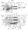
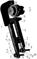
- the letter D indicates the tool changer device as a whole, according to an example of an embodiment of the invention.
- Said tool changer device D comprises a stationary head T, wherein is provided a cam exchanger mechanism S (of an already known type and therefore no longer shown hereinafter), that transforms uniform rotary input movement, provided by a gear motor unit M, into an ordered series of intermittent linear and rotary movements of an output shaft A, on which is mounted an arm 10 carrying a pair of tool grippers 11.
- the reference letters X-X indicate the axis of said shaft A, with respect to which said grippers 11 are supported on the arm 10 in diametrically opposing positions.
- Each gripper 11 comprises an outer jaw 11.1 and an inner jaw 11.2, with reference to the axis X-X. Said jaws 11.1, 11.2 can move with respect to one another with a straight-line movement.
- the axes of said rods 11.11, 11.21 and the relative bearings are parallel to one another and lie on a plane at right angles to said axis X-X.
- Said bearings 11.12, 11.22 are fixed in the box-type body 10.1 in a distal position with respect to the axis X-X of the shaft A.
- each of said rods 11.11, 11.12 has a respective free axial end 11.13, 11.23, near said axis X-X of the shaft A, wherein there is provided a respective slot-type through hole 11.14, 11.24, the axes of which lie along a plane at right angles to said axis X-X, the long axis being parallel to the axis of the respective rod and to the direction of sliding of the rod.
- said rods 11.11, 11.21 have a respective rack 11.15, 11.25, which extends along a plane at right angles to said axis X-X and is engaged with a corresponding pinion 12 with an axis Y-Y parallel to said axis X-X.
- cylindrical rod 11.21 supports a fixed radial pin 11.26, near said slot-type hole 11.24 and opposite said rack 11.25.
- a helical spring 13 is engaged at one end 13.1 with said pin 11.26, while with the other end 13.2 said spring 13 is fixed to the box-type body 10.1, in a distal position with respect to the axis X-X of the shaft A.
- said spring 13 normally and directly acts on the rod 11.21 of the inner jaw 11.2 causing said jaw to close, approaching the outer jaw 11.1, which in turn is indirectly acted on by said spring 13, by means of its rod 11.11, the rack 11.15, the pinion 12 and the other rack 11.25, and caused to close and approach the inner jaw 11.2.
- Said jaws 11.1, 11.2 at their respective free ends have respective idle contact rollers, 11.17, 11.27.
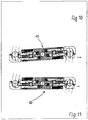
- a respective movable shutter 14 which comprises a cylindrical rod 14.2, with an axis Z-Z parallel to said axis X-X and positioned passing through the corresponding slot-type hole, and a coaxial cup-type body 14.1, projecting beyond said slot-type hole in a distal position with respect to said head T with the cam exchanger S. Furthermore, said rod 14.2 of each shutter 14 partly protrudes outside the box-type body 10.1, through a corresponding hole provided on a side face of said body 10.1 near the head T.
- a helical spring 14.3 is elastically compressed between said cup-type body 14.1 and a cover 14.4 fixed in a side face of said box-type body 10.1 distal from said head T.
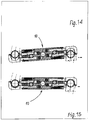
- Said length of travel of the rods 11.11 and 11.12 corresponds at least to the linear difference measured between the diameters of the flanges of two tool-holder cones with flanges of different diameters, which are exchanged "at random” and indifferently by means of the device according to the invention.
- each jaw rod 11.11, 11.21 ( fig. 5 ), around the respective slot-type hole 11.14, 11.24, has a surface portion 11.110, 11.210 that is conically countersunk towards said cup-type body 14.1 of the respective shutter 14 and, correspondingly, said cup-type body 14.1 of the respective shutter 14 has a lower outer edge 14.10 (which is near said slot-like hole) conically countersunk towards the top of the cup-type body and of a shape that is substantially complementary to that of said conically countersunk surface portion 11.110, 11.210 of said jaw rod 11.11, 11.21.
- the shutter spring 14.3 acts on said cup-type body 14.1 of the shutter 14 in contact with the respective jaw rod 11.1, 11.21 and in particular said lower outer edge 14.10 of the cup-type body 14.1, causing them to engage with said conically countersunk surface portion 11.110, 11.210 of the respective jaw rod 11.11, 11.21, thereby creating solid interference between the parts, which prevents axial movement or travel of the rod and therefore of the corresponding jaw 11.1, 11.2.
- This condition occurs when the gripper 11 grips the tool-holder cone to be changed and keeps it stably gripped in the tool changing phase.
- the tool changer device makes it possible to adapt first of all the opening and then the symmetrical closure of the gripper, according to the diameter of the tool-holder cone to be changed, by means of a simple mechanism, since opening and closing of the gripper are synchronized.
- Blocking of the tool-holder cone is made irreversible as soon as the device extracts the cones from their seats.
- the device according to the invention is necessarily used with a cam exchanger, whose rules of movement are specifically designed to prevent damage to the tool-holder cone when the gripper engages the cylindrical part and grips the tool-holder.
Landscapes
- Engineering & Computer Science (AREA)
- Mechanical Engineering (AREA)
- Automatic Tool Replacement In Machine Tools (AREA)
Claims (5)
- Vorrichtung (D) für den Werkzeugwechsel, umfassend einen stationären Kopf (T), versehen mit einem Nockenaustauschermechanismus (S), der die von einer Getriebemotoreinheit (M) zugeführte gleichmäßige Drehbewegung in eine geordnete Reihe von intermittierenden Linear- und Drehbewegungen einer Abtriebswelle (A) umwandelt, die mit einer Achse (X-X) versehen ist, und an der ein Arm (10) mit mindestens einem Werkzeuggreifer (11) montiert ist, und in dem der besagte Greifer (11) eine Außenbacke (11.1) und eine Innenbacke (11.2) umfasst, mit Bezug auf besagte Achse (X-X),
wobei- die besagten Backen (11.1, 11'.2) relativ untereinander mit geradliniger Bewegung durch entsprechende Stangen (11.11, 11.21) beweglich sind, die in einem kastenförmigen Körper (10.1) des besagten Arms (10) zum Gleiten in einer Ebene senkrecht zur besagten Achse (X-X) geführt (11.12, 11.22) werden,- jede der besagten Stangen (11.11, 11.12) ein entsprechendes freies axiales Ende (11.13, 11.23) aufweist, das sich proximal zur besagten Achse (X-X) befindet, in dem sich ein dazugehöriges durchgehendes Langloch (11.14, 11.24) befindet, dessen Achsen in einer orthogonalen Ebene zu der besagten Achse (X-X) liegen, wobei die Hauptachse parallel zur Bewegungsrichtung der jeweiligen Stange verläuft,- an gegenüberliegenden Teilen ihrer Seitenflächen die besagten Stangen (11.11, 11.21) jeweils eine Zahnstange (11.15, 11.25) aufweisen, die sich in einer Ebene orthogonal zur besagten Achse (X-X) erstreckt und mit einem entsprechenden Ritzel (12) mit einer Achse (Y-Y) parallel zur besagten Achse (X-X) der besagten Welle (A) verzahnt ist,- ein elastisches Mittel (13) eine (11.21) der besagten Stangen (11.11, 11.21) und die entsprechende Backe (11.2) zum Schließen direkt betätigt und sich in Bezug auf die andere Backe (11.1) nähert, die wiederum indirekt betätigt wird durch das gleiche besagte elastische Mittel (13) über ihre Stange (11.11) der bezüglichen Zahnstange (11.15) des besagten Ritzels (12) und der anderen Zahnstange (11.25) und verursacht ein Schließen, indem sie sich in Bezug auf die besagte Backe (11.2) nähert,wobei- in Übereinstimmung mit jedem der besagten Langlöcher (11.14, 11.24) ein entsprechender beweglicher Verschluss (14) vorhanden ist, der sich teilweise nach außen zu dem besagten kastenförmigen Körper (10.1) durch ein entsprechendes Loch proximal zum besagten Kopf (T) erstreckt,- ein elastisches Mittel (14.3) normalerweise den besagten Verschluss (14) teilweise über den kastenförmigen Körper (10.1) hinaus erstreckt und mit einer gegenüberliegenden Oberfläche des besagten Kopfes (T) in Kontakt hält und der besagte Verschluss (14) in diesem Zustand das entsprechende Langloch (11.14, 11.24) ohne Interferenz durchquert,wobei jede Stange (11.11, 11.21) um sein Langloch (11.14, 11.24) herum einen Teil der Oberfläche (11.110, 11.210) aufweist, die konisch zu einem entsprechenden Teil (14.1) des dazugehörigen Verschlusses (14) ausgestellt ist, und entsprechend der besagte entsprechende Teil (14.1) des dazugehörigen Verschlusses (14) einen Abschnitt (14.10) aufweist, der in der Nähe des besagten Langlochs liegt, konisch ausgestellt ist und eine Form aufweist, die im Wesentlichen komplementär zu der des besagten konisch ausgestellten Oberflächenteils (11.110, 11.210) der besagten Stange (11.11, 11.21) ist,
und wobei, in einem Zustand, in dem der besagte Verschluss (14) nicht mehr mit der besagten gegenüberliegenden Oberfläche des Kopfes (T) in Kontakt ist, das besagte elastische Mittel (14.3) den besagten entsprechenden Teil (14.1) des Verschlusses (14) in Kontakt mit der jeweiligen Stange (11.1, 11.21) betätigt, und der besagte Abschnitt (14.10) des Verschlusses (14) den besagten Teil der Oberfläche (11.110, 11.210) der jeweiligen Stange (11.11, 11.21) in Anspruch nimmt, wodurch eine feste Interferenz zwischen den Teilen selbst realisiert wird und der Hub der Stange und der entsprechenden Backe (11.1, 11.2) verhindert wird. - Eine Vorrichtung (D) für den Werkzeugwechsel gemäß Anspruch 1, dadurch gekennzeichnet, dass der besagte kastenförmige Körper (10.1) des besagten Arms (10) an einem jeweiligen distalen Ende der Welle (X-X) die besagten Backen (11.1, 11.2) mittels entsprechender zylindrischer Stangen (11.11, 11.21) außen stützt, die zum axialen Gleiten in ihren jeweiligen Kugelumlauflagern (11.12, 11.22) untergebracht sind, die in demselben besagten kastenförmigen Körper (10.1) befestigt sind, in dem die Achsen der besagten Stangen (11.11, 11.21) und der entsprechenden Lager parallel zueinander sind und in einer Ebene orthogonal zu der besagten Achse (X-X) liegen.
- Eine Vorrichtung (D) für den Werkzeugwechsel gemäß Anspruch 1, dadurch gekennzeichnet, dass der besagte Verschluss (14) eine zylindrische Stange (14.2) mit einer Achse (Z-Z) parallel zur besagten Achse (X-X) der Welle (A) aufweist und durch das entsprechende Langloch (11.14, 11.24) hindurchgeführt ist, sowie einen koaxialen becherförmigen Körper (14.1), der über das besagte Langloch hinaus in einer distalen Position in Bezug auf den besagten Kopf (T) herausragt, dadurch dass sich die besagte Stange (14.2) des besagten Verschlusses (14) teilweise außerhalb des kastenförmigen Körpers (10.1) durch ein entsprechendes Loch, das in einer Seitenfläche des besagten Körpers (10.1) proximal zum Kopf (T) vorgesehen ist, erstreckt; und dadurch dass ein elastisches Mittel (14.3) zwischen dem besagten becherförmigen Körper (14.1) und einer Abdeckung (14.4), die in einer Seitenfläche des besagten kastenförmigen Körper (10.1) distal vom besagten Kopf (T) befestigt ist, elastisch komprimiert ist, so dass die elastische Vorspannung des besagten elastischen Mittels die besagte Stange (14.2) des Verschlusses (14) normalerweise teilweise über den kastenförmigen Körper (10.1) hinaus und in Kontakt mit einer gegenüberliegenden Oberfläche des besagten Kopfes (T) hält.
- Eine Vorrichtung (D) für den Werkzeugwechsel gemäß Anspruch 1 und 3, dadurch gekennzeichnet, dass jede Stange (11.11, 11.21) um das jeweilige Langloch (11.14, 11.24) herum ein Oberflächenteil (11.110, 11.210) aufweist, das konisch zum besagten becherförmigen Körper (14.1) des jeweiligen Verschlusses (14) ausgestellt ist, und entsprechend der besagte becherförmige Körper (14.1) des jeweiligen Verschlusses (14) die untere Außenkante (14.10), die proximal zum besagten Langloch liegt, konisch zur Oberseite des becherförmigen Körpers hin ausgestellt ist und eine Form aufweist, die im Wesentlichen komplementär zu der des besagten konisch ausgestellten Oberflächenteils (11.110, 11.210) der besagten Stange (11.11, 11.21) ist.
- Eine Vorrichtung (D) für den Werkzeugwechsel gemäß einem jeden der vorhergehenden Ansprüche, dadurch gekennzeichnet, dass die Hublänge der besagten Stangen (11.11, 11.12) mindestens der linearen Messdifferenz zwischen den Durchmessern der Flansche zweier Werkzeugkegel mit Flanschen unterschiedlichen Durchmessers entspricht, die zufällig und gleichförmig durch die Vorrichtung (D) ausgetauscht werden, und dadurch gekennzeichnet, dass die besagte Länge im Wesentlichen gleich der Hauptachse der besagten Langlöcher (11.14, 11.24) der besagten Stangen (11.11, 11.21) ist.
Applications Claiming Priority (1)
| Application Number | Priority Date | Filing Date | Title |
|---|---|---|---|
| IT102016000114326A IT201600114326A1 (it) | 2016-11-11 | 2016-11-11 | Dispositivo di cambio utensile |
Publications (2)
| Publication Number | Publication Date |
|---|---|
| EP3321030A1 EP3321030A1 (de) | 2018-05-16 |
| EP3321030B1 true EP3321030B1 (de) | 2019-10-02 |
Family
ID=58228477
Family Applications (1)
| Application Number | Title | Priority Date | Filing Date |
|---|---|---|---|
| EP17001832.9A Not-in-force EP3321030B1 (de) | 2016-11-11 | 2017-11-09 | Werkzeugwechslervorrichtung |
Country Status (3)
| Country | Link |
|---|---|
| EP (1) | EP3321030B1 (de) |
| ES (1) | ES2764764T3 (de) |
| IT (1) | IT201600114326A1 (de) |
Families Citing this family (1)
| Publication number | Priority date | Publication date | Assignee | Title |
|---|---|---|---|---|
| CN115436459A (zh) * | 2022-04-10 | 2022-12-06 | 宁波华仪宁创智能科技有限公司 | 毛细针的自动化更换装置和方法 |
Family Cites Families (3)
| Publication number | Priority date | Publication date | Assignee | Title |
|---|---|---|---|---|
| JPS555212Y2 (de) * | 1974-02-27 | 1980-02-06 | ||
| JPS5766834A (en) * | 1980-10-14 | 1982-04-23 | Fanuc Ltd | Gripper for automatic tool replacer |
| JPS63123646A (ja) * | 1986-11-12 | 1988-05-27 | Brother Ind Ltd | 工具交換装置を備えた工作機械 |
-
2016
- 2016-11-11 IT IT102016000114326A patent/IT201600114326A1/it unknown
-
2017
- 2017-11-09 ES ES17001832T patent/ES2764764T3/es active Active
- 2017-11-09 EP EP17001832.9A patent/EP3321030B1/de not_active Not-in-force
Non-Patent Citations (1)
| Title |
|---|
| None * |
Also Published As
| Publication number | Publication date |
|---|---|
| ES2764764T3 (es) | 2020-06-04 |
| IT201600114326A1 (it) | 2018-05-11 |
| EP3321030A1 (de) | 2018-05-16 |
Similar Documents
| Publication | Publication Date | Title |
|---|---|---|
| EP3321031B1 (de) | Vorrichtung mit einer werkzeugwechslervorrichtung und einem linear bewegbaren kopf. | |
| EP2805794B1 (de) | Maschine zur Bearbeitung von Kurbelwellen | |
| JP4231016B2 (ja) | ツール交換装置 | |
| US4828276A (en) | Device for handling workpieces | |
| EP2803444A1 (de) | Werkzeugeinführer einer Handhabungsvorrichtung für das Auswechseln von Werkzeugen in Werkzeugmaschinen | |
| CN104690586A (zh) | 一种互锁式换刀机械手装置 | |
| EP3135428A1 (de) | Werkzeugmagazin und werkzeugaustauschvorrichtung | |
| EP3321030B1 (de) | Werkzeugwechslervorrichtung | |
| CN102896539A (zh) | 改进的刀具更换器 | |
| EP1386697A2 (de) | Spannvorrichtung für Werkstücke | |
| EP2714336B1 (de) | Aufspannvorrichtung für eine maschine zur anfertigung von schlüsselkopien | |
| MX2010010740A (es) | Tornillo provisto con un dispositivo de mordaza movil que tiene etapas de aproximacion y sujecion separadas en una matriz de maquina dobladora de tubos. | |
| EP1862255A1 (de) | Auswechselbares Werkzeug | |
| CN110052852A (zh) | 保持器及机床 | |
| CN204621646U (zh) | 一种互锁式换刀机械手装置 | |
| JP4276071B2 (ja) | 工作機械用の工具交換装置 | |
| KR101598635B1 (ko) | 공작기계의 자동 공구 교환장치 | |
| JP2005111660A (ja) | 工具取り扱いデバイス | |
| JP2014501180A (ja) | 改良型研削機械及び研削方法 | |
| JP5953241B2 (ja) | タレット旋盤 | |
| BR112020000014A2 (pt) | dispositivo de troca de ferramenta, máquina-ferramenta com tal dispositivo de troca de ferramenta e respectivo método | |
| JP7225311B2 (ja) | 把持システムおよび実験室自動化システム | |
| US1839401A (en) | Outward gripping chuck | |
| EP2567767A1 (de) | Werkzeugspindel | |
| JP4278467B2 (ja) | 工作機械 |
Legal Events
| Date | Code | Title | Description |
|---|---|---|---|
| PUAI | Public reference made under article 153(3) epc to a published international application that has entered the european phase |
Free format text: ORIGINAL CODE: 0009012 |
|
| STAA | Information on the status of an ep patent application or granted ep patent |
Free format text: STATUS: THE APPLICATION HAS BEEN PUBLISHED |
|
| AK | Designated contracting states |
Kind code of ref document: A1 Designated state(s): AL AT BE BG CH CY CZ DE DK EE ES FI FR GB GR HR HU IE IS IT LI LT LU LV MC MK MT NL NO PL PT RO RS SE SI SK SM TR |
|
| AX | Request for extension of the european patent |
Extension state: BA ME |
|
| STAA | Information on the status of an ep patent application or granted ep patent |
Free format text: STATUS: REQUEST FOR EXAMINATION WAS MADE |
|
| 17P | Request for examination filed |
Effective date: 20181112 |
|
| RBV | Designated contracting states (corrected) |
Designated state(s): AL AT BE BG CH CY CZ DE DK EE ES FI FR GB GR HR HU IE IS IT LI LT LU LV MC MK MT NL NO PL PT RO RS SE SI SK SM TR |
|
| RIC1 | Information provided on ipc code assigned before grant |
Ipc: B23Q 3/155 20060101AFI20190306BHEP |
|
| GRAP | Despatch of communication of intention to grant a patent |
Free format text: ORIGINAL CODE: EPIDOSNIGR1 |
|
| STAA | Information on the status of an ep patent application or granted ep patent |
Free format text: STATUS: GRANT OF PATENT IS INTENDED |
|
| INTG | Intention to grant announced |
Effective date: 20190426 |
|
| GRAS | Grant fee paid |
Free format text: ORIGINAL CODE: EPIDOSNIGR3 |
|
| GRAA | (expected) grant |
Free format text: ORIGINAL CODE: 0009210 |
|
| STAA | Information on the status of an ep patent application or granted ep patent |
Free format text: STATUS: THE PATENT HAS BEEN GRANTED |
|
| AK | Designated contracting states |
Kind code of ref document: B1 Designated state(s): AL AT BE BG CH CY CZ DE DK EE ES FI FR GB GR HR HU IE IS IT LI LT LU LV MC MK MT NL NO PL PT RO RS SE SI SK SM TR |
|
| REG | Reference to a national code |
Ref country code: GB Ref legal event code: FG4D |
|
| REG | Reference to a national code |
Ref country code: CH Ref legal event code: EP Ref country code: AT Ref legal event code: REF Ref document number: 1185669 Country of ref document: AT Kind code of ref document: T Effective date: 20191015 |
|
| REG | Reference to a national code |
Ref country code: DE Ref legal event code: R096 Ref document number: 602017007355 Country of ref document: DE |
|
| REG | Reference to a national code |
Ref country code: IE Ref legal event code: FG4D |
|
| PGFP | Annual fee paid to national office [announced via postgrant information from national office to epo] |
Ref country code: DE Payment date: 20191216 Year of fee payment: 3 |
|
| REG | Reference to a national code |
Ref country code: NL Ref legal event code: MP Effective date: 20191002 |
|
| REG | Reference to a national code |
Ref country code: LT Ref legal event code: MG4D |
|
| REG | Reference to a national code |
Ref country code: AT Ref legal event code: MK05 Ref document number: 1185669 Country of ref document: AT Kind code of ref document: T Effective date: 20191002 |
|
| PG25 | Lapsed in a contracting state [announced via postgrant information from national office to epo] |
Ref country code: PT Free format text: LAPSE BECAUSE OF FAILURE TO SUBMIT A TRANSLATION OF THE DESCRIPTION OR TO PAY THE FEE WITHIN THE PRESCRIBED TIME-LIMIT Effective date: 20200203 Ref country code: BG Free format text: LAPSE BECAUSE OF FAILURE TO SUBMIT A TRANSLATION OF THE DESCRIPTION OR TO PAY THE FEE WITHIN THE PRESCRIBED TIME-LIMIT Effective date: 20200102 Ref country code: FI Free format text: LAPSE BECAUSE OF FAILURE TO SUBMIT A TRANSLATION OF THE DESCRIPTION OR TO PAY THE FEE WITHIN THE PRESCRIBED TIME-LIMIT Effective date: 20191002 Ref country code: NL Free format text: LAPSE BECAUSE OF FAILURE TO SUBMIT A TRANSLATION OF THE DESCRIPTION OR TO PAY THE FEE WITHIN THE PRESCRIBED TIME-LIMIT Effective date: 20191002 Ref country code: AT Free format text: LAPSE BECAUSE OF FAILURE TO SUBMIT A TRANSLATION OF THE DESCRIPTION OR TO PAY THE FEE WITHIN THE PRESCRIBED TIME-LIMIT Effective date: 20191002 Ref country code: SE Free format text: LAPSE BECAUSE OF FAILURE TO SUBMIT A TRANSLATION OF THE DESCRIPTION OR TO PAY THE FEE WITHIN THE PRESCRIBED TIME-LIMIT Effective date: 20191002 Ref country code: LV Free format text: LAPSE BECAUSE OF FAILURE TO SUBMIT A TRANSLATION OF THE DESCRIPTION OR TO PAY THE FEE WITHIN THE PRESCRIBED TIME-LIMIT Effective date: 20191002 Ref country code: GR Free format text: LAPSE BECAUSE OF FAILURE TO SUBMIT A TRANSLATION OF THE DESCRIPTION OR TO PAY THE FEE WITHIN THE PRESCRIBED TIME-LIMIT Effective date: 20200103 Ref country code: NO Free format text: LAPSE BECAUSE OF FAILURE TO SUBMIT A TRANSLATION OF THE DESCRIPTION OR TO PAY THE FEE WITHIN THE PRESCRIBED TIME-LIMIT Effective date: 20200102 Ref country code: LT Free format text: LAPSE BECAUSE OF FAILURE TO SUBMIT A TRANSLATION OF THE DESCRIPTION OR TO PAY THE FEE WITHIN THE PRESCRIBED TIME-LIMIT Effective date: 20191002 Ref country code: PL Free format text: LAPSE BECAUSE OF FAILURE TO SUBMIT A TRANSLATION OF THE DESCRIPTION OR TO PAY THE FEE WITHIN THE PRESCRIBED TIME-LIMIT Effective date: 20191002 |
|
| PGFP | Annual fee paid to national office [announced via postgrant information from national office to epo] |
Ref country code: ES Payment date: 20200124 Year of fee payment: 3 |
|
| PG25 | Lapsed in a contracting state [announced via postgrant information from national office to epo] |
Ref country code: HR Free format text: LAPSE BECAUSE OF FAILURE TO SUBMIT A TRANSLATION OF THE DESCRIPTION OR TO PAY THE FEE WITHIN THE PRESCRIBED TIME-LIMIT Effective date: 20191002 Ref country code: RS Free format text: LAPSE BECAUSE OF FAILURE TO SUBMIT A TRANSLATION OF THE DESCRIPTION OR TO PAY THE FEE WITHIN THE PRESCRIBED TIME-LIMIT Effective date: 20191002 Ref country code: IS Free format text: LAPSE BECAUSE OF FAILURE TO SUBMIT A TRANSLATION OF THE DESCRIPTION OR TO PAY THE FEE WITHIN THE PRESCRIBED TIME-LIMIT Effective date: 20200224 |
|
| PGFP | Annual fee paid to national office [announced via postgrant information from national office to epo] |
Ref country code: CZ Payment date: 20191128 Year of fee payment: 3 |
|
| REG | Reference to a national code |
Ref country code: ES Ref legal event code: FG2A Ref document number: 2764764 Country of ref document: ES Kind code of ref document: T3 Effective date: 20200604 |
|
| PG25 | Lapsed in a contracting state [announced via postgrant information from national office to epo] |
Ref country code: AL Free format text: LAPSE BECAUSE OF FAILURE TO SUBMIT A TRANSLATION OF THE DESCRIPTION OR TO PAY THE FEE WITHIN THE PRESCRIBED TIME-LIMIT Effective date: 20191002 |
|
| REG | Reference to a national code |
Ref country code: DE Ref legal event code: R097 Ref document number: 602017007355 Country of ref document: DE |
|
| PG2D | Information on lapse in contracting state deleted |
Ref country code: IS |
|
| PG25 | Lapsed in a contracting state [announced via postgrant information from national office to epo] |
Ref country code: DK Free format text: LAPSE BECAUSE OF FAILURE TO SUBMIT A TRANSLATION OF THE DESCRIPTION OR TO PAY THE FEE WITHIN THE PRESCRIBED TIME-LIMIT Effective date: 20191002 Ref country code: LU Free format text: LAPSE BECAUSE OF NON-PAYMENT OF DUE FEES Effective date: 20191109 Ref country code: EE Free format text: LAPSE BECAUSE OF FAILURE TO SUBMIT A TRANSLATION OF THE DESCRIPTION OR TO PAY THE FEE WITHIN THE PRESCRIBED TIME-LIMIT Effective date: 20191002 Ref country code: RO Free format text: LAPSE BECAUSE OF FAILURE TO SUBMIT A TRANSLATION OF THE DESCRIPTION OR TO PAY THE FEE WITHIN THE PRESCRIBED TIME-LIMIT Effective date: 20191002 Ref country code: MC Free format text: LAPSE BECAUSE OF FAILURE TO SUBMIT A TRANSLATION OF THE DESCRIPTION OR TO PAY THE FEE WITHIN THE PRESCRIBED TIME-LIMIT Effective date: 20191002 Ref country code: IS Free format text: LAPSE BECAUSE OF FAILURE TO SUBMIT A TRANSLATION OF THE DESCRIPTION OR TO PAY THE FEE WITHIN THE PRESCRIBED TIME-LIMIT Effective date: 20200202 |
|
| PLBE | No opposition filed within time limit |
Free format text: ORIGINAL CODE: 0009261 |
|
| STAA | Information on the status of an ep patent application or granted ep patent |
Free format text: STATUS: NO OPPOSITION FILED WITHIN TIME LIMIT |
|
| REG | Reference to a national code |
Ref country code: BE Ref legal event code: MM Effective date: 20191130 |
|
| PG25 | Lapsed in a contracting state [announced via postgrant information from national office to epo] |
Ref country code: IT Free format text: LAPSE BECAUSE OF FAILURE TO SUBMIT A TRANSLATION OF THE DESCRIPTION OR TO PAY THE FEE WITHIN THE PRESCRIBED TIME-LIMIT Effective date: 20191002 Ref country code: SK Free format text: LAPSE BECAUSE OF FAILURE TO SUBMIT A TRANSLATION OF THE DESCRIPTION OR TO PAY THE FEE WITHIN THE PRESCRIBED TIME-LIMIT Effective date: 20191002 Ref country code: SM Free format text: LAPSE BECAUSE OF FAILURE TO SUBMIT A TRANSLATION OF THE DESCRIPTION OR TO PAY THE FEE WITHIN THE PRESCRIBED TIME-LIMIT Effective date: 20191002 |
|
| 26N | No opposition filed |
Effective date: 20200703 |
|
| PG25 | Lapsed in a contracting state [announced via postgrant information from national office to epo] |
Ref country code: IE Free format text: LAPSE BECAUSE OF NON-PAYMENT OF DUE FEES Effective date: 20191109 Ref country code: FR Free format text: LAPSE BECAUSE OF NON-PAYMENT OF DUE FEES Effective date: 20191202 |
|
| PG25 | Lapsed in a contracting state [announced via postgrant information from national office to epo] |
Ref country code: BE Free format text: LAPSE BECAUSE OF NON-PAYMENT OF DUE FEES Effective date: 20191130 Ref country code: SI Free format text: LAPSE BECAUSE OF FAILURE TO SUBMIT A TRANSLATION OF THE DESCRIPTION OR TO PAY THE FEE WITHIN THE PRESCRIBED TIME-LIMIT Effective date: 20191002 |
|
| PG25 | Lapsed in a contracting state [announced via postgrant information from national office to epo] |
Ref country code: CY Free format text: LAPSE BECAUSE OF FAILURE TO SUBMIT A TRANSLATION OF THE DESCRIPTION OR TO PAY THE FEE WITHIN THE PRESCRIBED TIME-LIMIT Effective date: 20191002 |
|
| REG | Reference to a national code |
Ref country code: DE Ref legal event code: R119 Ref document number: 602017007355 Country of ref document: DE |
|
| REG | Reference to a national code |
Ref country code: CH Ref legal event code: PL |
|
| PG25 | Lapsed in a contracting state [announced via postgrant information from national office to epo] |
Ref country code: HU Free format text: LAPSE BECAUSE OF FAILURE TO SUBMIT A TRANSLATION OF THE DESCRIPTION OR TO PAY THE FEE WITHIN THE PRESCRIBED TIME-LIMIT; INVALID AB INITIO Effective date: 20171109 Ref country code: MT Free format text: LAPSE BECAUSE OF FAILURE TO SUBMIT A TRANSLATION OF THE DESCRIPTION OR TO PAY THE FEE WITHIN THE PRESCRIBED TIME-LIMIT Effective date: 20191002 Ref country code: CZ Free format text: LAPSE BECAUSE OF NON-PAYMENT OF DUE FEES Effective date: 20201109 |
|
| PG25 | Lapsed in a contracting state [announced via postgrant information from national office to epo] |
Ref country code: CH Free format text: LAPSE BECAUSE OF NON-PAYMENT OF DUE FEES Effective date: 20201130 Ref country code: LI Free format text: LAPSE BECAUSE OF NON-PAYMENT OF DUE FEES Effective date: 20201130 |
|
| PG25 | Lapsed in a contracting state [announced via postgrant information from national office to epo] |
Ref country code: DE Free format text: LAPSE BECAUSE OF NON-PAYMENT OF DUE FEES Effective date: 20210601 |
|
| REG | Reference to a national code |
Ref country code: ES Ref legal event code: FD2A Effective date: 20220131 |
|
| PG25 | Lapsed in a contracting state [announced via postgrant information from national office to epo] |
Ref country code: TR Free format text: LAPSE BECAUSE OF FAILURE TO SUBMIT A TRANSLATION OF THE DESCRIPTION OR TO PAY THE FEE WITHIN THE PRESCRIBED TIME-LIMIT Effective date: 20191002 Ref country code: ES Free format text: LAPSE BECAUSE OF NON-PAYMENT OF DUE FEES Effective date: 20201110 |
|
| PG25 | Lapsed in a contracting state [announced via postgrant information from national office to epo] |
Ref country code: MK Free format text: LAPSE BECAUSE OF FAILURE TO SUBMIT A TRANSLATION OF THE DESCRIPTION OR TO PAY THE FEE WITHIN THE PRESCRIBED TIME-LIMIT Effective date: 20191002 |
|
| GBPC | Gb: european patent ceased through non-payment of renewal fee |
Effective date: 20211109 |
|
| PG25 | Lapsed in a contracting state [announced via postgrant information from national office to epo] |
Ref country code: GB Free format text: LAPSE BECAUSE OF NON-PAYMENT OF DUE FEES Effective date: 20211109 |