EP3320385B1 - Optical products - Google Patents
Optical products Download PDFInfo
- Publication number
- EP3320385B1 EP3320385B1 EP16825055.3A EP16825055A EP3320385B1 EP 3320385 B1 EP3320385 B1 EP 3320385B1 EP 16825055 A EP16825055 A EP 16825055A EP 3320385 B1 EP3320385 B1 EP 3320385B1
- Authority
- EP
- European Patent Office
- Prior art keywords
- features
- portions
- optical
- image
- optical product
- Prior art date
- Legal status (The legal status is an assumption and is not a legal conclusion. Google has not performed a legal analysis and makes no representation as to the accuracy of the status listed.)
- Active
Links
- 230000003287 optical effect Effects 0.000 title claims description 407
- 230000008859 change Effects 0.000 claims description 60
- 238000009826 distribution Methods 0.000 claims description 19
- 238000000576 coating method Methods 0.000 claims description 11
- 239000011248 coating agent Substances 0.000 claims description 10
- 238000004806 packaging method and process Methods 0.000 claims description 10
- 210000001747 pupil Anatomy 0.000 claims description 10
- 239000003814 drug Substances 0.000 claims description 8
- 239000000049 pigment Substances 0.000 claims description 7
- 238000012795 verification Methods 0.000 claims description 5
- 239000000853 adhesive Substances 0.000 claims description 4
- 230000001070 adhesive effect Effects 0.000 claims description 3
- 230000000875 corresponding effect Effects 0.000 description 71
- 239000000463 material Substances 0.000 description 52
- 238000000034 method Methods 0.000 description 43
- 239000000758 substrate Substances 0.000 description 41
- 239000010410 layer Substances 0.000 description 31
- 238000004519 manufacturing process Methods 0.000 description 26
- 239000011135 tin Substances 0.000 description 21
- 239000010408 film Substances 0.000 description 20
- -1 for example Substances 0.000 description 19
- 230000000694 effects Effects 0.000 description 18
- 230000000737 periodic effect Effects 0.000 description 15
- 239000000976 ink Substances 0.000 description 13
- 239000005020 polyethylene terephthalate Substances 0.000 description 13
- 229920000139 polyethylene terephthalate Polymers 0.000 description 13
- 239000004743 Polypropylene Substances 0.000 description 12
- 229920001684 low density polyethylene Polymers 0.000 description 12
- 239000004702 low-density polyethylene Substances 0.000 description 12
- 229910052751 metal Inorganic materials 0.000 description 12
- 239000002184 metal Substances 0.000 description 12
- 229920001155 polypropylene Polymers 0.000 description 12
- 239000003086 colorant Substances 0.000 description 10
- XEKOWRVHYACXOJ-UHFFFAOYSA-N Ethyl acetate Chemical compound CCOC(C)=O XEKOWRVHYACXOJ-UHFFFAOYSA-N 0.000 description 9
- 230000008447 perception Effects 0.000 description 9
- 239000004417 polycarbonate Substances 0.000 description 9
- 229920000515 polycarbonate Polymers 0.000 description 9
- 239000004800 polyvinyl chloride Substances 0.000 description 8
- 229920002120 photoresistant polymer Polymers 0.000 description 7
- 230000008569 process Effects 0.000 description 7
- 230000002829 reductive effect Effects 0.000 description 7
- 239000011347 resin Substances 0.000 description 7
- 229920005989 resin Polymers 0.000 description 7
- 229920010126 Linear Low Density Polyethylene (LLDPE) Polymers 0.000 description 6
- GWEVSGVZZGPLCZ-UHFFFAOYSA-N Titan oxide Chemical compound O=[Ti]=O GWEVSGVZZGPLCZ-UHFFFAOYSA-N 0.000 description 6
- 238000006073 displacement reaction Methods 0.000 description 6
- 239000005026 oriented polypropylene Substances 0.000 description 6
- 239000000123 paper Substances 0.000 description 6
- 229920000642 polymer Polymers 0.000 description 6
- RYGMFSIKBFXOCR-UHFFFAOYSA-N Copper Chemical compound [Cu] RYGMFSIKBFXOCR-UHFFFAOYSA-N 0.000 description 5
- BQCADISMDOOEFD-UHFFFAOYSA-N Silver Chemical compound [Ag] BQCADISMDOOEFD-UHFFFAOYSA-N 0.000 description 5
- 229910052782 aluminium Inorganic materials 0.000 description 5
- XAGFODPZIPBFFR-UHFFFAOYSA-N aluminium Chemical compound [Al] XAGFODPZIPBFFR-UHFFFAOYSA-N 0.000 description 5
- 229910052802 copper Inorganic materials 0.000 description 5
- 239000010949 copper Substances 0.000 description 5
- 239000006185 dispersion Substances 0.000 description 5
- 238000005286 illumination Methods 0.000 description 5
- 230000001681 protective effect Effects 0.000 description 5
- 229910052709 silver Inorganic materials 0.000 description 5
- 239000004332 silver Substances 0.000 description 5
- 241000385223 Villosa iris Species 0.000 description 4
- 238000010521 absorption reaction Methods 0.000 description 4
- 230000008901 benefit Effects 0.000 description 4
- 239000000975 dye Substances 0.000 description 4
- 238000005516 engineering process Methods 0.000 description 4
- 238000010348 incorporation Methods 0.000 description 4
- 230000001788 irregular Effects 0.000 description 4
- 239000000203 mixture Substances 0.000 description 4
- 229920006255 plastic film Polymers 0.000 description 4
- 239000002985 plastic film Substances 0.000 description 4
- 238000012545 processing Methods 0.000 description 4
- DKPFZGUDAPQIHT-UHFFFAOYSA-N Butyl acetate Natural products CCCCOC(C)=O DKPFZGUDAPQIHT-UHFFFAOYSA-N 0.000 description 3
- 239000003929 acidic solution Substances 0.000 description 3
- 230000002378 acidificating effect Effects 0.000 description 3
- 239000003637 basic solution Substances 0.000 description 3
- 230000002596 correlated effect Effects 0.000 description 3
- 230000007797 corrosion Effects 0.000 description 3
- 238000005260 corrosion Methods 0.000 description 3
- 230000001419 dependent effect Effects 0.000 description 3
- 238000000609 electron-beam lithography Methods 0.000 description 3
- 238000004049 embossing Methods 0.000 description 3
- 230000006870 function Effects 0.000 description 3
- FUZZWVXGSFPDMH-UHFFFAOYSA-N hexanoic acid Chemical compound CCCCCC(O)=O FUZZWVXGSFPDMH-UHFFFAOYSA-N 0.000 description 3
- 238000001093 holography Methods 0.000 description 3
- 238000002164 ion-beam lithography Methods 0.000 description 3
- 239000003960 organic solvent Substances 0.000 description 3
- 239000007787 solid Substances 0.000 description 3
- 239000004698 Polyethylene Substances 0.000 description 2
- 239000004676 acrylonitrile butadiene styrene Substances 0.000 description 2
- 238000003491 array Methods 0.000 description 2
- 230000005540 biological transmission Effects 0.000 description 2
- 239000000919 ceramic Substances 0.000 description 2
- 239000011247 coating layer Substances 0.000 description 2
- 230000000295 complement effect Effects 0.000 description 2
- 238000009459 flexible packaging Methods 0.000 description 2
- 239000011521 glass Substances 0.000 description 2
- 150000002500 ions Chemical class 0.000 description 2
- 230000033001 locomotion Effects 0.000 description 2
- 239000011159 matrix material Substances 0.000 description 2
- 238000000059 patterning Methods 0.000 description 2
- 229920003023 plastic Polymers 0.000 description 2
- 239000004033 plastic Substances 0.000 description 2
- 229920003229 poly(methyl methacrylate) Polymers 0.000 description 2
- 229920000573 polyethylene Polymers 0.000 description 2
- 229920006254 polymer film Polymers 0.000 description 2
- 239000002861 polymer material Substances 0.000 description 2
- 229920000307 polymer substrate Polymers 0.000 description 2
- 239000004926 polymethyl methacrylate Substances 0.000 description 2
- 229920000915 polyvinyl chloride Polymers 0.000 description 2
- 239000011253 protective coating Substances 0.000 description 2
- 230000010076 replication Effects 0.000 description 2
- 239000000126 substance Substances 0.000 description 2
- 239000010409 thin film Substances 0.000 description 2
- 229910000906 Bronze Inorganic materials 0.000 description 1
- 241001465754 Metazoa Species 0.000 description 1
- 229920007019 PC/ABS Polymers 0.000 description 1
- ATJFFYVFTNAWJD-UHFFFAOYSA-N Tin Chemical compound [Sn] ATJFFYVFTNAWJD-UHFFFAOYSA-N 0.000 description 1
- RTAQQCXQSZGOHL-UHFFFAOYSA-N Titanium Chemical compound [Ti] RTAQQCXQSZGOHL-UHFFFAOYSA-N 0.000 description 1
- HCHKCACWOHOZIP-UHFFFAOYSA-N Zinc Chemical compound [Zn] HCHKCACWOHOZIP-UHFFFAOYSA-N 0.000 description 1
- XECAHXYUAAWDEL-UHFFFAOYSA-N acrylonitrile butadiene styrene Chemical compound C=CC=C.C=CC#N.C=CC1=CC=CC=C1 XECAHXYUAAWDEL-UHFFFAOYSA-N 0.000 description 1
- 229920000122 acrylonitrile butadiene styrene Polymers 0.000 description 1
- 229910045601 alloy Inorganic materials 0.000 description 1
- 239000000956 alloy Substances 0.000 description 1
- 230000015572 biosynthetic process Effects 0.000 description 1
- 239000010974 bronze Substances 0.000 description 1
- 238000004364 calculation method Methods 0.000 description 1
- 230000001010 compromised effect Effects 0.000 description 1
- 230000001276 controlling effect Effects 0.000 description 1
- KUNSUQLRTQLHQQ-UHFFFAOYSA-N copper tin Chemical compound [Cu].[Sn] KUNSUQLRTQLHQQ-UHFFFAOYSA-N 0.000 description 1
- 230000003247 decreasing effect Effects 0.000 description 1
- 230000007547 defect Effects 0.000 description 1
- 239000003989 dielectric material Substances 0.000 description 1
- 238000009792 diffusion process Methods 0.000 description 1
- 238000005315 distribution function Methods 0.000 description 1
- 239000011888 foil Substances 0.000 description 1
- 235000013305 food Nutrition 0.000 description 1
- PCHJSUWPFVWCPO-UHFFFAOYSA-N gold Chemical compound [Au] PCHJSUWPFVWCPO-UHFFFAOYSA-N 0.000 description 1
- 239000010931 gold Substances 0.000 description 1
- 229910052737 gold Inorganic materials 0.000 description 1
- 238000002347 injection Methods 0.000 description 1
- 239000007924 injection Substances 0.000 description 1
- 238000007689 inspection Methods 0.000 description 1
- 230000003993 interaction Effects 0.000 description 1
- 238000003475 lamination Methods 0.000 description 1
- 230000000670 limiting effect Effects 0.000 description 1
- 238000012886 linear function Methods 0.000 description 1
- 239000007769 metal material Substances 0.000 description 1
- 150000002739 metals Chemical class 0.000 description 1
- 230000003278 mimic effect Effects 0.000 description 1
- 238000012986 modification Methods 0.000 description 1
- 230000004048 modification Effects 0.000 description 1
- 239000011087 paperboard Substances 0.000 description 1
- 238000000206 photolithography Methods 0.000 description 1
- 229920005644 polyethylene terephthalate glycol copolymer Polymers 0.000 description 1
- 230000000750 progressive effect Effects 0.000 description 1
- 210000001525 retina Anatomy 0.000 description 1
- 230000035807 sensation Effects 0.000 description 1
- 230000003595 spectral effect Effects 0.000 description 1
- 238000001228 spectrum Methods 0.000 description 1
- 229910052718 tin Inorganic materials 0.000 description 1
- 229910052719 titanium Inorganic materials 0.000 description 1
- 239000010936 titanium Substances 0.000 description 1
- 238000012546 transfer Methods 0.000 description 1
- 229910052725 zinc Inorganic materials 0.000 description 1
- 239000011701 zinc Substances 0.000 description 1
Images


Classifications
-
- B—PERFORMING OPERATIONS; TRANSPORTING
- B42—BOOKBINDING; ALBUMS; FILES; SPECIAL PRINTED MATTER
- B42D—BOOKS; BOOK COVERS; LOOSE LEAVES; PRINTED MATTER CHARACTERISED BY IDENTIFICATION OR SECURITY FEATURES; PRINTED MATTER OF SPECIAL FORMAT OR STYLE NOT OTHERWISE PROVIDED FOR; DEVICES FOR USE THEREWITH AND NOT OTHERWISE PROVIDED FOR; MOVABLE-STRIP WRITING OR READING APPARATUS
- B42D25/00—Information-bearing cards or sheet-like structures characterised by identification or security features; Manufacture thereof
- B42D25/20—Information-bearing cards or sheet-like structures characterised by identification or security features; Manufacture thereof characterised by a particular use or purpose
- B42D25/21—Information-bearing cards or sheet-like structures characterised by identification or security features; Manufacture thereof characterised by a particular use or purpose for multiple purposes
-
- B—PERFORMING OPERATIONS; TRANSPORTING
- B42—BOOKBINDING; ALBUMS; FILES; SPECIAL PRINTED MATTER
- B42D—BOOKS; BOOK COVERS; LOOSE LEAVES; PRINTED MATTER CHARACTERISED BY IDENTIFICATION OR SECURITY FEATURES; PRINTED MATTER OF SPECIAL FORMAT OR STYLE NOT OTHERWISE PROVIDED FOR; DEVICES FOR USE THEREWITH AND NOT OTHERWISE PROVIDED FOR; MOVABLE-STRIP WRITING OR READING APPARATUS
- B42D25/00—Information-bearing cards or sheet-like structures characterised by identification or security features; Manufacture thereof
- B42D25/30—Identification or security features, e.g. for preventing forgery
- B42D25/342—Moiré effects
-
- B—PERFORMING OPERATIONS; TRANSPORTING
- B42—BOOKBINDING; ALBUMS; FILES; SPECIAL PRINTED MATTER
- B42D—BOOKS; BOOK COVERS; LOOSE LEAVES; PRINTED MATTER CHARACTERISED BY IDENTIFICATION OR SECURITY FEATURES; PRINTED MATTER OF SPECIAL FORMAT OR STYLE NOT OTHERWISE PROVIDED FOR; DEVICES FOR USE THEREWITH AND NOT OTHERWISE PROVIDED FOR; MOVABLE-STRIP WRITING OR READING APPARATUS
- B42D25/00—Information-bearing cards or sheet-like structures characterised by identification or security features; Manufacture thereof
- B42D25/20—Information-bearing cards or sheet-like structures characterised by identification or security features; Manufacture thereof characterised by a particular use or purpose
- B42D25/29—Securities; Bank notes
-
- B—PERFORMING OPERATIONS; TRANSPORTING
- B42—BOOKBINDING; ALBUMS; FILES; SPECIAL PRINTED MATTER
- B42D—BOOKS; BOOK COVERS; LOOSE LEAVES; PRINTED MATTER CHARACTERISED BY IDENTIFICATION OR SECURITY FEATURES; PRINTED MATTER OF SPECIAL FORMAT OR STYLE NOT OTHERWISE PROVIDED FOR; DEVICES FOR USE THEREWITH AND NOT OTHERWISE PROVIDED FOR; MOVABLE-STRIP WRITING OR READING APPARATUS
- B42D25/00—Information-bearing cards or sheet-like structures characterised by identification or security features; Manufacture thereof
- B42D25/30—Identification or security features, e.g. for preventing forgery
- B42D25/324—Reliefs
-
- B—PERFORMING OPERATIONS; TRANSPORTING
- B42—BOOKBINDING; ALBUMS; FILES; SPECIAL PRINTED MATTER
- B42D—BOOKS; BOOK COVERS; LOOSE LEAVES; PRINTED MATTER CHARACTERISED BY IDENTIFICATION OR SECURITY FEATURES; PRINTED MATTER OF SPECIAL FORMAT OR STYLE NOT OTHERWISE PROVIDED FOR; DEVICES FOR USE THEREWITH AND NOT OTHERWISE PROVIDED FOR; MOVABLE-STRIP WRITING OR READING APPARATUS
- B42D25/00—Information-bearing cards or sheet-like structures characterised by identification or security features; Manufacture thereof
- B42D25/30—Identification or security features, e.g. for preventing forgery
- B42D25/351—Translucent or partly translucent parts, e.g. windows
-
- B—PERFORMING OPERATIONS; TRANSPORTING
- B42—BOOKBINDING; ALBUMS; FILES; SPECIAL PRINTED MATTER
- B42D—BOOKS; BOOK COVERS; LOOSE LEAVES; PRINTED MATTER CHARACTERISED BY IDENTIFICATION OR SECURITY FEATURES; PRINTED MATTER OF SPECIAL FORMAT OR STYLE NOT OTHERWISE PROVIDED FOR; DEVICES FOR USE THEREWITH AND NOT OTHERWISE PROVIDED FOR; MOVABLE-STRIP WRITING OR READING APPARATUS
- B42D25/00—Information-bearing cards or sheet-like structures characterised by identification or security features; Manufacture thereof
- B42D25/30—Identification or security features, e.g. for preventing forgery
- B42D25/355—Security threads
-
- B—PERFORMING OPERATIONS; TRANSPORTING
- B42—BOOKBINDING; ALBUMS; FILES; SPECIAL PRINTED MATTER
- B42D—BOOKS; BOOK COVERS; LOOSE LEAVES; PRINTED MATTER CHARACTERISED BY IDENTIFICATION OR SECURITY FEATURES; PRINTED MATTER OF SPECIAL FORMAT OR STYLE NOT OTHERWISE PROVIDED FOR; DEVICES FOR USE THEREWITH AND NOT OTHERWISE PROVIDED FOR; MOVABLE-STRIP WRITING OR READING APPARATUS
- B42D25/00—Information-bearing cards or sheet-like structures characterised by identification or security features; Manufacture thereof
- B42D25/30—Identification or security features, e.g. for preventing forgery
- B42D25/36—Identification or security features, e.g. for preventing forgery comprising special materials
- B42D25/373—Metallic materials
-
- B—PERFORMING OPERATIONS; TRANSPORTING
- B42—BOOKBINDING; ALBUMS; FILES; SPECIAL PRINTED MATTER
- B42D—BOOKS; BOOK COVERS; LOOSE LEAVES; PRINTED MATTER CHARACTERISED BY IDENTIFICATION OR SECURITY FEATURES; PRINTED MATTER OF SPECIAL FORMAT OR STYLE NOT OTHERWISE PROVIDED FOR; DEVICES FOR USE THEREWITH AND NOT OTHERWISE PROVIDED FOR; MOVABLE-STRIP WRITING OR READING APPARATUS
- B42D25/00—Information-bearing cards or sheet-like structures characterised by identification or security features; Manufacture thereof
- B42D25/30—Identification or security features, e.g. for preventing forgery
- B42D25/36—Identification or security features, e.g. for preventing forgery comprising special materials
- B42D25/378—Special inks
-
- B—PERFORMING OPERATIONS; TRANSPORTING
- B42—BOOKBINDING; ALBUMS; FILES; SPECIAL PRINTED MATTER
- B42D—BOOKS; BOOK COVERS; LOOSE LEAVES; PRINTED MATTER CHARACTERISED BY IDENTIFICATION OR SECURITY FEATURES; PRINTED MATTER OF SPECIAL FORMAT OR STYLE NOT OTHERWISE PROVIDED FOR; DEVICES FOR USE THEREWITH AND NOT OTHERWISE PROVIDED FOR; MOVABLE-STRIP WRITING OR READING APPARATUS
- B42D25/00—Information-bearing cards or sheet-like structures characterised by identification or security features; Manufacture thereof
- B42D25/40—Manufacture
- B42D25/405—Marking
- B42D25/425—Marking by deformation, e.g. embossing
-
- G—PHYSICS
- G02—OPTICS
- G02B—OPTICAL ELEMENTS, SYSTEMS OR APPARATUS
- G02B30/00—Optical systems or apparatus for producing three-dimensional [3D] effects, e.g. stereoscopic images
- G02B30/20—Optical systems or apparatus for producing three-dimensional [3D] effects, e.g. stereoscopic images by providing first and second parallax images to an observer's left and right eyes
- G02B30/26—Optical systems or apparatus for producing three-dimensional [3D] effects, e.g. stereoscopic images by providing first and second parallax images to an observer's left and right eyes of the autostereoscopic type
- G02B30/27—Optical systems or apparatus for producing three-dimensional [3D] effects, e.g. stereoscopic images by providing first and second parallax images to an observer's left and right eyes of the autostereoscopic type involving lenticular arrays
-
- G—PHYSICS
- G02—OPTICS
- G02B—OPTICAL ELEMENTS, SYSTEMS OR APPARATUS
- G02B30/00—Optical systems or apparatus for producing three-dimensional [3D] effects, e.g. stereoscopic images
- G02B30/20—Optical systems or apparatus for producing three-dimensional [3D] effects, e.g. stereoscopic images by providing first and second parallax images to an observer's left and right eyes
- G02B30/34—Stereoscopes providing a stereoscopic pair of separated images corresponding to parallactically displaced views of the same object, e.g. 3D slide viewers
- G02B30/36—Stereoscopes providing a stereoscopic pair of separated images corresponding to parallactically displaced views of the same object, e.g. 3D slide viewers using refractive optical elements, e.g. prisms, in the optical path between the images and the observer
-
- G—PHYSICS
- G02—OPTICS
- G02B—OPTICAL ELEMENTS, SYSTEMS OR APPARATUS
- G02B5/00—Optical elements other than lenses
- G02B5/18—Diffraction gratings
-
- G—PHYSICS
- G02—OPTICS
- G02B—OPTICAL ELEMENTS, SYSTEMS OR APPARATUS
- G02B6/00—Light guides; Structural details of arrangements comprising light guides and other optical elements, e.g. couplings
- G02B6/10—Light guides; Structural details of arrangements comprising light guides and other optical elements, e.g. couplings of the optical waveguide type
- G02B6/12—Light guides; Structural details of arrangements comprising light guides and other optical elements, e.g. couplings of the optical waveguide type of the integrated circuit kind
- G02B6/13—Integrated optical circuits characterised by the manufacturing method
-
- G—PHYSICS
- G02—OPTICS
- G02B—OPTICAL ELEMENTS, SYSTEMS OR APPARATUS
- G02B6/00—Light guides; Structural details of arrangements comprising light guides and other optical elements, e.g. couplings
- G02B6/24—Coupling light guides
- G02B6/42—Coupling light guides with opto-electronic elements
Definitions
- the present application generally relates to optical products, masters (e.g., master and/or daughter shims) for fabricating an optical product, and methods for manufacturing the masters and optical products.
- the optical product can be configured, when illuminated, to reproduce by reflected (or refracted) or transmitted light, one or more 3D images (e.g., one or more images that appear three-dimensional) of at least a part of one or more 3D objects.
- Optical products can be used for a variety of purposes such as to reproduce a 3D image. Such products can be placed on decorative signs, labels, packaging, and consumer goods. Some optical products can be used as an anti-counterfeit feature, for example, on currency (e.g., a banknote). Holograms have traditionally been used as a counterfeit deterrent. However, this technology has become so widespread with hundreds if not thousands of holographic shops around the world that holograms are now viewed as having poor security. Optically variable inks and optically variable magnetic inks have also enjoyed for the past decade a high security place on banknotes. However, these products have now been simulated or have been even made from similar materials as the originals that these security elements are now being questioned as a high security feature.
- Manufacturing optical products can utilize a master to fabricate the optical product.
- a master can be either a negative or positive master.
- a negative master can form a surface of the optical product that is complementary to the surface of the master.
- a positive master can provide a surface for the optical product that is substantially similar to the surface of the master. Examples of current optical products can be found in the following:
- WO2006/013215 discloses a diffractive device and a method of creating said device displaying a three-dimensional preferably achromatic image, especially imitating a real or an imaginary relief scene, a flat microrelief or otherwise modulated structure of a diffractive type, the structure comprising a system of diffraction zones which are arranged so that in places of diffractive structure corresponding to places of the relief scene the diffraction zones have periodicity and orientation that cause deflection of incident light in the same direction as the relief scene deflects an incident light, thus achieving a visible three-dimensional and largely achromatic sensation of image, corresponding to the relief scene, when observing the diffractive structure regardless of conditions of lighting.
- WO2011/066990 discloses a security element for a security paper, such as value documents, comprising a carrier having a surface area which is subdivided into a plurality of pixels which in each case comprise at least one optically active facet.
- the plurality of pixels comprises respectively several of the optically active facets having the same orientation per pixel, and the facets are oriented in such a way that the surface area can be perceived by a viewer as a surface that projects to the front and/or the rear relative to its actual three-dimensional shape.
- WO2014/060089 discloses an optically variable surface pattern comprising a carrier, which has a first and a second surface region, wherein the two surface regions are designed such that the first surface region in a first solid angle range ( ⁇ 1), presents a first view that appears curved and the second surface region in a second solid angle range ( ⁇ 2), which differs from the first solid angle range ( ⁇ 1) presents a second view that appears curved.
- US2013/052373 discloses an optical authentication component visible in reflection having a structure imprinted on a substrate of index no, a thin layer, made of a dielectric material having a refractive index n 1 , deposited on the structure, and a layer made of a material having an index n2 similar to no, encapsulating the structure coated with the thin layer.
- the structure has a first pattern modulated by a second pattern
- the first pattern is a bas-relief with an array of facets, having shapes which are defined to simulate an image in relief of an object in relief
- the second pattern is a periodic grating that modulates the first pattern which produces, after the thin layer has been deposited and the structure has been encapsulated, a first color at a first viewing angle and a different second color at a second viewing angle, obtained by azimuthal rotation of the component.
- the present invention relates to an optical product as defined in independent claim 1.
- Preferred embodiments of the optical product are defined in the dependent claims.
- Various embodiments described herein that do not fall within the scope of the claims comprise a master for fabricating an optical product.
- the master can comprise a first surface and a second surface opposite the first surface.
- the second surface can comprise a plurality of portions. Each portion can correspond to a point on a surface of the 3D object.
- Each portion can comprise features corresponding to non-holographic elements on the optical product.
- a gradient (e.g., slope) in the features can correlate to an inclination of the surface of the 3D object at the corresponding point.
- an orientation of the features can correlate to an orientation of the surface of the 3D object at the corresponding point.
- various embodiments described herein that do not fall within the scope of the claims include a method for manufacturing a master for fabricating an optical product.
- the method can comprise providing a 2D data file configured to describe the 3D image.
- the data file can comprise a plurality of portions. Each portion can correspond to one or more points on a surface of the 3D object. Each portion can comprise features of intensity corresponding to non-holographic elements on the optical product. A gradient in intensity can correlate to an inclination of the surface of the 3D object at the one or more corresponding points.
- an orientation of the features can correlate to an orientation of the surface of the 3D object at the one or more corresponding points.
- the method can also comprise manufacturing the master based at least in part on the 2D data file.
- Certain embodiments described herein of a master, optical product, and/or data file can also include one or more of the following (1) a majority of the plurality of portions comprising a single non-holographic feature, (2) a majority of the plurality of portions comprising one or more non-holographic features discontinuous with one or more non-holographic features in surrounding adjacent portions, (3) a majority of the plurality of portions comprising one or more non-holographic features having different orientations as one or more non-holographic features in surrounding adjacent portions, and/or (4) one or more non-holographic features comprising non-linear features when viewed in a cross-section.
- each portion comprising one or more non-holographic features can be configured to produce at least part of the image without relying on diffraction (1) at a viewing angle at least between 20 degrees to 160 degrees relative to a plane of the optical product as the optical product is tilted and (2) at a viewing angle at least between 20 degrees to 90 degrees relative to the plane of the optical product as the optical product is rotated at least throughout the range of 90 degrees (rotated at least throughout the range of 180 degrees, rotated at least throughout the range of 270 degrees, or rotated at least throughout the range of 360 degrees) in the plane of the optical product.
- the size of the portion may assist in reducing iridescence or a change in color with change in angle of view or change in angle of illumination such as results when tilting the product with respect to the viewer and/or source of illumination.
- the optical product does not exhibit a rainbow-like array of displayed colors where colors simultaneously appear in the order of a rainbow.
- the color of light emanating from the product does not appear to change when tilting the product or the viewer with respect to the product or the illumination with respect to the product, for example, in order of progressively increasing wavelength or in order of progressively decreasing wavelength (e.g., in progressive order of the arrangement of colors in the rainbow).
- the size of the portion may be sufficiently large to produce light that can pass through a circular pupil 5 mm in diameter located 24 inches from the product that includes a plurality of colors that mix together to form white light. Accordingly, for a person viewing the product with their eye positioned 24 inches from the product and having a pupil of 5 mm in diameter, light from the product will enter the eye and be mixed together to form white light. The person thus does not see iridescence or change in color with change in angle of view or angle of illumination or tilt of the product. Other factor besides the size of the portion may contribute to this effect, even if the size of the portion is not sufficiently large on its own to cause this lack of iridescence. For example, not having multiple grating like features in a single portion may reduce this effect.
- having a large number or percentage of portions that do not have multiple grating like features but instead have a single surface may contribute to reducing iridescence or change in color with angle.
- having features with a curved surface within the portion may help counter the iridescent effect.
- the curved features may, for example, enhance mixing of different colors so that white light is sensed by the viewer. Even if multiple features are included in a portion, these features may be curved and this curvature may potentially reduce the iridescence.
- the amount of portions that have features that are oriented differently from each other may be increased and the amount of portions that have a shift in phase or otherwise introduce a discontinuity may be increased, possibly resulting in increased mixing of color components and reducing this effect of diffractive spectral dispersion.
- the size of the portion may not be limited to produce light that can pass through a circular pupil 5 mm in diameter located 24 inches.
- a size of the portion can be 75 microns such that all the colors generated by the portion can be captured by a 4mm pupil located at about 24 inches.
- the embodiments disclosed herein can include articles including laminates, films, or layers including a plurality of optical features configured such that a viewer viewing the article from a first direction perceives a first set of distinct images and perceives a second set of distinct images when viewing the article from a second direction. At the first direction, the viewer does not perceive the second set of distinct images. At the second direction, the viewer does not perceive the first set of distinct images. There may be little to no overlap between the first and the second set of images.
- the first and the second set of images can include one or more patterns, one or more characters, one or more objects, one or more numbers, one or more graphics, and/or one or more letters.
- the laminates, films, or layers can be reflective or transmissive.
- incident light reflected from the plurality of optical features can have varying levels of brightness based on the viewing direction which results in the perception of depth in the different distinct images.
- the laminate, film or layer including optical features that can produce different distinct images when viewed from different directions can be tilted about an axis in the plane of the laminate, film or layer to flip between the first and the second set of distinct images.
- the laminate, film or layer including optical features that can produce different distinct images when viewed from different directions can be rotated to flip between the first and the second set of distinct images viewable when light passes through the laminate, film or layer.
- the embodiments disclosed herein can be advantageously manufactured on a large industrial scale.
- the laminates, films, or layers including optical features that can produce different distinct images when viewed from different directions can be manufactured on polymeric substrates, such as, for example, polyethylene terephthalate (PET), oriented polypropylene (OPP), low density polyethylene (LDPE), linear low density polyethylene (LLDPE), polypropylene (PP), polyvinyl chloride (PVC), polycarbonate (PC) or any other type of plastic film.
- PET polyethylene terephthalate
- OPP oriented polypropylene
- LDPE low density polyethylene
- LLDPE linear low density polyethylene
- PP polypropylene
- PVC polyvinyl chloride
- PC polycarbonate
- the polymeric substrate can be clear.
- the polymeric substrates can have a thickness less than or equal to 300 microns (e.g., less than or equal to 250 microns, less than or equal to 200 microns, less than or equal to 150 microns, less than or equal to 100 microns, less than or equal to 50 microns, less than or equal to 25 microns, less than or equal to 15 microns, etc.) and/or from 10 microns to 300 microns, or any range within this range (e.g., from 10 microns to 250 microns, from 12.5 microns to 250 microns, from 12.5 microns to 200 microns, from 10 microns to 25 microns, from 10 microns to 15 microns, etc.).
- Polymeric substrates including laminates, films, or layers comprising optical features that can produce different distinct images when viewed from different directions having such a thickness can be formed into security threads that can be incorporated into a banknote which has similar thickness.
- the different distinct images can appear bright and can be seen under a variety of lighting conditions.
- the first and the second viewing directions can be oriented (e.g., tilted and/or rotated) with respect to each other by an angle from 10 degrees to 60 degrees.
- different distinct non-overlapping images can be perceived when the laminate, film or layer including optical features that can produce different distinct images when viewed from different directions is tilted about an axis in the plane of the laminate, film or layer by an angle less than or equal to 20 degrees.
- different distinct non-overlapping images can be perceived when the laminate, film or layer including optical features that can produce different distinct images when viewed from different directions is rotated about an axis perpendicular to the plane of the laminate, film or layer by an angle less than or equal to 45 degrees.
- the plurality of optical features that can produce different distinct images when viewed from different directions can be coated with a reflective material, such as, for example, aluminum, silver, copper or some other reflective metal.
- the thickness of the reflective metal can be greater than or equal to 45 nm (e.g., 50 nm, 55 nm, 60 nm, etc.) and/or be in a range from 45 nm to 100 nm, or any range within this range (e.g., from 45 nm to 85 nm, from 45 nm to 75 nm, from 50 nm to 85 nm, etc.) such that the laminate, film or layer is opaque.
- the thickness of the reflective metal can be less than 45 nm (e.g., 10 nm, 15 nm, 20 nm, 25 nm, etc.) and/or be in a range from 10 nm to 44.9 nm, or any range within this range (e.g., from 10 nm to 40 nm, from 10 nm to 35 nm, from 10 nm to 30 nm, etc.) such that the laminate, film or layer is semi-transparent.
- nm e.g., 10 nm, 15 nm, 20 nm, 25 nm, etc.
- the thickness of the reflective metal can be less than 45 nm (e.g., 10 nm, 15 nm, 20 nm, 25 nm, etc.) and/or be in a range from 10 nm to 44.9 nm, or any range within this range (e.g., from 10 nm to 40 nm, from 10 nm to 35
- the plurality of the optical features and/or the reflective material coating the plurality of the optical features can be covered with a protective coating (e.g., an organic resin coat) to protect the plurality of the optical features and/or the reflective material coating the plurality of the optical features from corrosion from acidic or basic solutions or organic solvents such as gasoline and ethyl acetate or butyl acetate.
- a protective coating e.g., an organic resin coat
- the plurality of optical features can include relief features disposed on the surface of the polymeric substrate.
- the plurality of optical features can include grooves or facets disposed on the surface of the polymeric substrate.
- the orientation, slope/gradient and other physical attributes of the optical features can be determined from the images that are desired to be reproduced.
- the images can be in the form of a dot matrix or a 3D image.
- the laminates, films and layers including the plurality of optical features that can produce different distinct images when viewed from different directions can be integrated with one or more lenses (e.g., a curved lens or a Fresnel lens or an array of lenses such as a lenticular lens).
- the focal length of the lens can be approximately equal to the thickness of polymeric substrate.
- the optical features can be incorporated with one or more prisms or mirrors.
- the laminates, film or layers including the plurality of optical features that can produce different distinct images when viewed from different directions can be manufactured using the systems and methods disclosed.
- the disclosure provides an optical product comprising a first surface and a second surface opposite the first surface.
- the second surface is configured, when illuminated, to reproduce by reflected or transmitted light, a first 3D image of at least part of a first 3D object at a first angle of view, and a second 3D image of at least part of a second 3D object at a second angle of view.
- the optical product does not reproduce the second 3D image
- the optical product does not reproduce the first 3D image.
- the second surface comprises a first plurality of portions and a second plurality of portions.
- Each portion of the first plurality of portions corresponds to a point on a surface of the first 3D object, each portion comprising first non-holographic features configured to produce at least part of the first 3D image of the first 3D object without relying on diffraction.
- Each portion of the second plurality of portions corresponds to a point on a surface of the second 3D object, each portion comprising second non-holographic features configured to produce at least part of the second 3D image of the second 3D object without relying on diffraction.
- a gradient in the first non-holographic features can correlate to an inclination of the surface of the first 3D object at the corresponding point, and an orientation of the first non-holographic features can correlate to an orientation of the surface of the first 3D object at the corresponding point.
- a gradient in the second non-holographic features can correlate to an inclination of the surface of the second 3D object at the corresponding point, and an orientation of the second non-holographic features can correlate to an orientation of the surface of the second 3D object at the corresponding point.
- the optical product can comprise borders surrounding at least part of the portions of the first and second plurality of portions.
- some of the portions of the first and second plurality of portions can form a periodic array.
- the periodic array can include a striped, zigzagged, checkerboard, or houndstooth pattern.
- the portions of the first and second plurality of portions can form an aperiodic array.
- the optical product when tilted in a direction from the first angle of view to the second angle of view, the first 3D image can appear to change to the second 3D image in a direction orthogonal to the direction from the first angle of view to the second angle of view.
- the first or second non-holographic features can have a largest dimension between 1 ⁇ m and 35 ⁇ m.
- some of the portions of the first and second plurality of portions can comprise features discontinuous with features in surrounding adjacent portions.
- the first or second features when viewed from a top or front view, can comprise linear features corresponding to a substantially smooth region of the surface of the first or second 3D object respectively.
- the first or second features when viewed from a top or front view, can comprise non-linear features corresponding to a curved region of the surface of the first or second 3D object respectively.
- the inclination of the surface of the first 3D object can comprise a polar angle from a first reference line of the first 3D object, and the orientation of the surface of the first 3D object can comprise an azimuth angle from a second reference line orthogonal to the first reference line of the first 3D object.
- the inclination of the surface of the second 3D object can comprise a polar angle from a first reference line of the second 3D object
- the orientation of the surface of the second 3D object can comprise an azimuth angle from a second reference line orthogonal to the first reference line of the second 3D object.
- the second surface can comprise a reflective surface.
- the second surface can comprise holographic features.
- the holographic features can be integrated into at least one of the portions of the first and second plurality of portions.
- the first or second 3D object can comprise an irregularly shaped object.
- the first or second 3D object can comprise one or more alphanumeric characters.
- the second surface can further comprise additional features that when illuminated, do not reproduce a part of the first or second 3D object.
- the optical product can be configured to provide authenticity verification on an item for security.
- the item can be currency, a credit card, a debit card, a passport, a driver's license, an identification card, a document, a tamper evident container or packaging, or a bottle of pharmaceuticals.
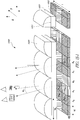
- the disclosure further provides an optical product comprising an array of optical elements (e.g., lenses, prisms, or mirrors), a first plurality of portions, and a second plurality of portions.
- the first plurality of portions is disposed under the array of lenses, prisms, or mirrors.
- Individual ones of the first plurality of portions correspond to a point on a surface of a first 3D object and comprise first non-holographic features configured to produce at least part of a first 3D image of the first 3D object without relying on diffraction.
- the second plurality of portions is disposed under the array of lenses, prisms, or mirrors.
- Individual ones of the second plurality of portions correspond to a point on a surface of a second 3D object and comprise second non-holographic features configured to produce at least part of a second 3D image of the second 3D object without relying on diffraction.
- the array of lenses, prisms, or mirrors presents the first 3D image for viewing without presenting the second 3D image for viewing, and at a second viewing angle different from the first viewing angle, the array of lenses, prisms, or mirrors presents for viewing the second 3D image without presenting the first 3D image for viewing.
- the array of optical elements can comprise an array of lenses, an array of microlenses, an array of curved mirrors, or an array of prisms.
- the array of optical elements can comprise a 1D lenticular lens array.
- the array of optical elements can comprise a 2D microlens array.
- the array of optical elements can comprise an array of prisms.
- the array of optical lenses can comprise an array of mirrors with optical power.
- a gradient in the first non-holographic features can correlate to an inclination of the surface of the first 3D object at the corresponding point, and an orientation of the first non-holographic features can correlate to an orientation of the surface of the first 3D object at the corresponding point.
- a gradient in the second non-holographic features can correlate to an inclination of the surface of the second 3D object at the corresponding point, and an orientation of the second non-holographic features can correlate to an orientation of the surface of the second 3D object at the corresponding point.
- some of the portions of the first and second plurality of portions can form a periodic array.
- the inclination of the surface of the first 3D object can comprise a polar angle from a first reference line of the first 3D object, and the orientation of the surface of the first 3D object can comprise an azimuth angle from a second reference line orthogonal to the first reference line of the first 3D object.
- the inclination of the surface of the second 3D object can comprise a polar angle from a first reference line of the second 3D object
- the orientation of the surface of the second 3D object can comprise an azimuth angle from a second reference line orthogonal to the first reference line of the second 3D object.
- the first and second non-holographic features can comprise a reflective surface.
- the first or second 3D object can comprise an irregularly shaped object.
- the first or second 3D object can comprise one or more alphanumeric characters.
- the optical products described herein can be configured to provide authenticity verification on an item for security.
- the item can be currency, a credit card, a debit card, a passport, a driver's license, an identification card, a document, a tamper evident container or packaging, or a bottle of pharmaceuticals.
- the optical product can be configured to be applied onto a lighting product, such as, for example, a light emitting diode (LED) based lighting system to control the LED based lighting system.
- the optical product can include portions and/or optical features which do not rely on phase information to generate an image of an object.
- the portions and/or optical features can be configured to be substantially achromatic.
- the optical product can include non-holographic features configured to produce images that are achromatic.
- the non-holographic features can provide no diffractive or interference color (e.g., no wavelength dispersion or rainbows or rainbow effects).
- the non-holographic features can be colored.
- the non-holographic features can comprise a tint, an ink, dye, or pigment where absorption can provide color.
- Various embodiments disclosed herein can be used for security documents, in particular, as security threads in bank notes or as a patch or as a window.
- Other security items such as passports, ID cards, chip cards, credit cards, stock certificates and other investment securities, vouchers, admission tickets and commercial packages that protect items of value such as CD's, medicinal drugs, car and aircraft parts, etc. may also be protected against counterfeiting using the concepts and embodiments described herein.
- a master e.g., a master and/or daughter shim
- the optical product when illuminated, reproduces an overt 3D image (e.g., an image that appears 3D to the naked eye) of a 3D object.
- the reflective surface of various embodiments of the optical product can produce a brighter mirror-like image produced by reflecting (or refracting) light incident on the surface.
- the surface normals of the 3D object are mimicked as surface relief on the master and/or optical product.
- the surface relief on the master and/or optical product can be thinner than the 3D object, yet produce the same appearance of the 3D object.
- the optical product can advantageously be used in applications for flexible packaging, brand identification, tamper evident containers, currency (e.g., a banknote), decoding messages, authenticity, and security, etc.
- Some security applications include incorporation of small detailed features, incorporation of non-symmetrical features, incorporation of machine readable features, etc.
- the optical product can be incorporated into an item as an embedded feature, a hot stamp feature, a windowed thread feature, or a transparent window feature.
- the optical product can be a patch, a window, or a thread.
- the optical product can have a thickness of less than 30 ⁇ m, less than 25 ⁇ m, or less than 15 ⁇ m.
- the image can appear 3D by the naked eye.
- the image can be seen at a viewing angle between 20 degrees to 160 degrees, between 15 degrees to 165 degrees, between 10 degrees to 170 degrees, between 5 degrees to 175 degrees, or between 0 degrees to 180 degrees relative to the plane of the item (e.g., relative to the banknote plane) as the item is tilted.
- the image can be viewable within one or more of these viewing angle ranges relative to the plane of the item.
- the image can be seen at a viewing angle between 20 degrees to 90 degrees, between 15 degrees to 90 degrees, between 10 degrees to 90 degrees, between 5 degrees to 90 degrees, or between 0 degrees to 90 degrees relative to the normal of the item as the item is rotated the normal of the item (e.g., in the plane of the item).
- the image can be viewable and/or visible within one or more of these viewing angle ranges as the item is rotated (e.g., rotated at least throughout the range of 90 degrees, rotated at least throughout the range of 180 degrees, rotated at least throughout the range of 270 degrees, or rotated at least throughout the range of 360 degrees) about the normal of the item (e.g., in the plane of the item).
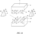
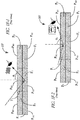
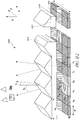
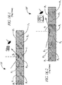
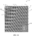
- FIG 1A schematically illustrates an example master 10 for fabricating an optical product 10' in accordance with certain embodiments described herein.
- the master 10 can include a first surface 11 and a second surface 12 opposite the first surface 11.
- the second surface 12 can include a plurality of portions P 1 , P 2 , ... P n .
- Each portion P n can correspond to a plurality of portions P' 1 , P' 2 , ... P' n on the optical product 10'.
- the plurality of portions P' 1 , P' 2 , ... P' n on the optical product 10' can also be referred to as a cell, pixel, or a tile.
- Each portion P' n can have a length between 7 ⁇ m and 100 ⁇ m, or any range within this range (e.g., between 7 ⁇ m and 50 ⁇ m, between 7 ⁇ m and 35 ⁇ m, between 12.5 ⁇ m and 100 ⁇ m, between 12.5 ⁇ m and 50 ⁇ m, between 12.5 ⁇ m and 35 ⁇ m, between 35 ⁇ m and 55 ⁇ m, between 40 ⁇ m and 50 ⁇ m, etc.).
- Each portion P' n can have a width between 7 ⁇ m and 100 ⁇ m, or any range within this range (e.g., between 7 ⁇ m and 50 ⁇ m, between 7 ⁇ m and 35 ⁇ m, between 12.5 ⁇ m and 100 ⁇ m, between 12.5 ⁇ m and 50 ⁇ m, between 12.5 ⁇ m and 35 ⁇ m, between 35 ⁇ m and 55 ⁇ m, between 40 ⁇ m and 50 ⁇ m, etc.). Accordingly, in various embodiments, the aspect ratio of each portion P' n can be 1:1 or 1:1.1.
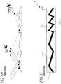
- Each portion P n of the master 10 (and each portion P' n of the optical product 10') can correspond to a point S 1 , S 2 , ... S n on a surface S of the 3D object 50.
- Each portion P n can include features F 1 , F 2 , ... F n corresponding to elements E 1 , E 2 , ... E n , e.g., non-holographic elements, on the optical product 10'.
- a gradient (e.g., slope) in the features F 1 , F 2 , ... F n can correlate to an inclination (e.g., slope) of the surface S of the 3D object 50 at the corresponding point S 1 , S 2 , ... S n .
- an orientation of the features F 1 , F 2 , ... F n can correlate to an orientation of the surface S of the 3D object 50 at the corresponding point S 1 , S 2 , ... S n .
- an optical product 10' fabricated using the example master 10 can be configured, when illuminated, to reproduce by reflected (or refracted) light, a 3D image 50' (e.g., an image that appears 3D) of at least a part of a 3D object 50.
- the image can be observed by the naked eye and under various lighting conditions (e.g., specular, diffuse, and/or low light conditions).
- the optical product 10' can be used on a variety of products to reproduce a 3D image 50' of at least a part of a 3D object 50.
- the optical product 10' can be placed on decorative signs, advertisements, labels (e.g., self-adhesive labels), packaging (e.g., consumer paper board packaging and/or flexible packaging), consumer goods, collectible cards (e.g., baseball cards), etc.
- the optical product 10' can also be advantageously used for authenticity and security applications.
- the optical product 10' can be placed on currency (e.g., a banknote), credit cards, debit cards, passports, driver's licenses, identification cards, documents, tamper evident containers and packaging, bottles of pharmaceuticals, etc.
- the optical product 10' can be a reflective or transmissive device.
- the optical product 10' can include reflective material (e.g., reflective metal such as aluminum, copper, or silver disposed on the plurality of elements E 1 , E 2 , ... E n , or a transparent, relatively high refractive index material such as ZnS or TiO 2 disposed on the plurality of elements E 1 , E 2 , ... E n creating a semi-transmitting/partially reflective boundary).
- the optical product 10' can be reflective or transmissive.
- the optical product 10' can be partially reflective or partially transmissive. The thickness of the reflective material at which the optical product 10' is reflective or transmissive can depend on the chemical composition of the reflective material.
- the optical product 10' can include a reflective surface 12' from which light can reflect from the elements E 1 , E 2 , ... E n to reproduce the image 50' of the 3D object 50 or at least part of the 3D object 50.
- the optical product 10' can be made of a reflective metal (e.g., aluminum, copper, or silver), a semi-transparent metal, or a material (e.g., polymer, ceramic, or glass) coated with a reflective metal. Reflective coatings that employ non-metallic material can also be employed.
- the thickness of the coating layer can be greater than or equal to 45 nm (e.g., 50 nm, 55 nm, 60 nm, etc.) and/or be in a range from 45 nm to 100 nm, or any range within this range (e.g., from 45 nm to 85 nm, from 45 nm to 75 nm, from 50 nm to 85 nm, etc.) such that the layer is opaque.
- the thickness of the reflective metal can be less than 45 nm (e.g., 10 nm, 15 nm, 20 nm, 25 nm, etc.) and/or be in a range from 10 nm to 44.9 nm, or any range within this range (e.g., from 10 nm to 40 nm, from 10 nm to 35 nm, from 10 nm to 30 nm, etc.) such that the layer is semi-transparent (e.g., 30% transparent, 40% transparent, 50% transparent, 60% transparent, 70% transparent, or any ranges inbetween these values, etc.).
- E n can reflect light towards or away from the observer's eye to reproduce the image 50' the 3D object 50.
- the elements E 1 , E 2 , ... E n can reflect light towards the observer's eye in bright areas, and reflect light away from the observer's eye in dark areas.
- the slopes of the elements E n can be configured to create the 3D depth perception of the image. For example, elements E n with less steep slopes can cause light to reflect toward the observer's eye creating more brightness, while elements E n with steeper slopes can cause light to reflect away from the observer's eye creating more darkness.
- the optical product 10' can include a layer (e.g., a coating) of a transparent, relatively high refractive index material such as, for example, ZnS or TiO 2 .
- a transparent, relatively high refractive index material such as, for example, ZnS or TiO 2 .
- light can transmit through the material and can also reflect at each of the elements E 1 , E 2 , ... E n due to the presence of the relatively high index layer which can create index mismatch and results in Fresnel reflection.
- the relatively high index material can be up to a full visible wavelength in thickness in some embodiments. If a color tint is used, the relatively high index material can be up to a 1 ⁇ 4 of a visible wavelength in thickness in some embodiments.
- the optical product 10' can include a protective covering, e.g., an organic resin, to protect the elements E 1 , E 2 , ... E n and/or any coating layer from corrosion from acidic or basic solutions or organic solvents such as gasoline and ethyl acetate or butyl acetate.
- the protective covering can also provide protection during subsequent processing steps and use of the optical product 10' (e.g., during the manufacturing of currency and/or by general handling by the public).
- the optical product 10' can be placed on or in another surface (e.g., as an embedded feature, a hot stamped feature such as a patch, a windowed thread feature, or a transparent window feature).
- the optical product 10' can be placed under another surface (e.g., laminated under a film and/or cast cured).
- the optical product 10' can be placed between two other surfaces (e.g., hot stamped on another surface and laminated under a film). Additional features associated with the optical product 10' will become apparent with the disclosure herein of the master 10 for fabricating the optical product 10'.
- the image 50' of at least part of the 3D object 50 can be reproduced when the optical product 10' is illuminated.
- the image 50' can be reproduced by a multitude of relatively small mirrors (e.g., each of the elements E 1 , E 2 , ...
- E n having both a length and width between 7 ⁇ m and 100 ⁇ m, or any range within this range (e.g., between 7 ⁇ m and 50 ⁇ m, between 7 ⁇ m and 35 ⁇ m, between 12.5 ⁇ m and 100 ⁇ m, between 12.5 ⁇ m and 50 ⁇ m, between 12.5 ⁇ m and 35 ⁇ m, between 35 ⁇ m and 55 ⁇ m, between 40 ⁇ m and 50 ⁇ m, etc.) which can be curved (e.g., have a freeform curvature) or planar.
- a reflective surface of the optical product 10' can provide a surface for specular reflection, such that the image 50' can be produced by the reflected light (e.g., like a mirror). Accordingly, various embodiments can produce a bright, high quality image. Some embodiments can also utilize techniques for producing diffuse reflection, e.g., for special or desired effects. Furthermore, the image 50' can be a substantially similar reproduction (e.g., with similar details), an approximate reproduction (e.g., with less details), and/or a scaled copy (e.g., scaled up or down in size) of the 3D object 50 or part of the 3D object 50.
- the 3D object 50 to be reproduced is not particularly limited and can advantageously include rotationally non-symmetrical and/or irregularly shaped objects, as well as symmetrical and/or regularly shaped objects.
- the 3D object 50 can include one or more alphanumeric characters and/or symbols.
- the 3D object 50 can include one or more text, one or more alphabetic characters, one or more numeric characters, one or more letters, one or more numbers, one or more symbols, one or more punctuation marks, one or more mathematical operators, etc.
- the 3D object 50 can also include one or more graphical images or logos, e.g., a company logo, a team logo, product branding designs, etc.
- the 3D object 50 can include irregularly shaped features in addition to planar and curved features.
- the 3D object 50 can comprise animals, humans, plants or trees, landscapes, buildings, cars, boats, airplanes, bicycles, furniture, office equipment, sports equipment, foods, drinks, personal care items, flags, emblems, symbols like country, company or product symbols including trademarks, or parts thereof or groups or combination of these items with or without other items.
- the objects may be cartoon or artistic renditions. A wide range of other objects are possible.
- the image 50' can be seen at various viewing angles (e.g., between 20 degrees to 160 degrees, between 15 degrees to 165 degrees, between 10 degrees to 170 degrees, between 5 degrees to 175 degrees, or between 0 degrees to 180 degrees relative to the plane of the item (e.g., relative to the banknote plane).
- various viewing angles e.g., between 20 degrees to 160 degrees, between 15 degrees to 165 degrees, between 10 degrees to 170 degrees, between 5 degrees to 175 degrees, or between 0 degrees to 180 degrees relative to the plane of the item (e.g., relative to the banknote plane).
- different sets of elements E 1 , E 2 , ... E n can be seen by the observer to provide the different images of the 3D object.
- the image can be seen at a viewing angle between 20 degrees to 90 degrees, between 15 degrees to 90 degrees, between 10 degrees to 90 degrees, between 5 degrees to 90 degrees, or between 0 degrees to 90 degrees relative to the normal of the item as the item is rotated about the normal of the item.
- the image can be viewable within one or more of these viewing angle ranges as the item is rotated (e.g., rotated at least throughout the range of 90 degrees, rotated at least throughout the range of 180 degrees, rotated at least throughout the range of 270 degrees, or rotated at least throughout the range of 360 degrees) about the normal of the item.
- the image 50' can be substantially without iridescence or change in color with angle.
- the optical product 10' does not provide a color change over an angular range around a viewing direction over the collection pupil having a size of 4.0 mm or 5.0 mm located at a distance of 24 inches.
- the angular range is 2 degrees, 3 degrees, 4 degrees, 5 degrees, 6 degrees, 7 degrees, 10 degrees, 12 degrees, 15 degrees, 17 degrees, 20 degrees, 25 degrees, or any range between these values.
- the viewing direction can be from 0 and 90 degrees with respect to a normal to a surface of the product 10', or any range within this range (e.g., from 5 to 85 degrees, from 5 to 75 degrees, from 5 to 60 degrees, from 10 to 60 degrees, from 10 to 55 degrees, etc.).
- the size of the portions P' 1 , P' 2 , ... P' n can have a length and width between 7 ⁇ m and 200 ⁇ m, or any range within this range (e.g., between 7 ⁇ m and 50 ⁇ m, between 7 ⁇ m and 35 ⁇ m, between 12.5 ⁇ m and 100 ⁇ m, between 12.5 ⁇ m and 50 ⁇ m, between 12.5 ⁇ m and 35 ⁇ m, between 35 ⁇ m and 55 ⁇ m, between 40 ⁇ m and 50 ⁇ m, between about 65 ⁇ m and 80 ⁇ m , between about 50 ⁇ m and 100 ⁇ m, between about 60 ⁇ m and 90 ⁇ m, between about 100 ⁇ m and 200 ⁇ m, etc.).
- any range within this range e.g., between 7 ⁇ m and 50 ⁇ m, between 7 ⁇ m and 35 ⁇ m, between 12.5 ⁇ m and 100 ⁇ m, between 12.5 ⁇ m and 50 ⁇ m, between 12.5 ⁇ m and 35 ⁇ m,
- the portions P' n may be small enough such that the portions P' n are not resolvable by a human observer under normal viewing conditions (e.g., a reading distance of 18 to 24 inches between the eye and the item to be viewed).
- the portions P' n may be big enough such that the cone of light passing through the pupil (e.g., 4 mm or 5 mm in diameter) is small enough such that the eye may see a majority of the colors mixed as white light at a distance of 18-24 inches.
- a majority e.g., greater than 50%, greater than 55%, greater than 60%, greater than 65%, greater than 70%, greater than 80%, greater than 90%, and any ranges in between these values
- a majority e.g., greater than 50%, greater than 55%, greater than 60%, greater than 65%, greater than 70%, greater than 80%, greater than 90%, and any ranges in between these values
- the plurality of portions P' 1 , P' 2 , ... P' n on the optical product 10' can include a single non-holographic element E 1 (as opposed to a plurality of spaced apart non-holographic elements E n that may resemble a grating-like feature).
- grating-like features can cause light to be dispersed with some of the light collected by the pupil of the eye.
- the light captured by the pupil may appear as a color. Accordingly, in various embodiments of the optical product 10' that have a majority of the plurality of portions P' 1 , P' 2 , ... P' n having not more than a single non-holographic reflective or refractive element E 1 , unwanted color caused by grating-like features may possibly be substantially reduced and/or eliminated. Similarly, color change with angle of tilt can be reduced. In some embodiments, at least 20%, at least 30%, at least 40%, at least 50%, at least 60%, at least 70%, at least 80%, at least 90%, or any ranges in between these values) of the plurality of portions P' 1 , P' 2 , ...
- P' n on the optical product 10' can include a single non-holographic element E 1 .
- the single element may be slowly varying and/or substantially flat.
- the maximum average slope per portion with a single feature is less than 1 ⁇ 2, less than 1/3, less than 1 ⁇ 4, less than 1/5, less than 1/6, potentially flat, and any ranges in between these values depending on feature height and width.
- the elements E n can be discontinuous and/or have different orientation with non-holographic elements E 1 , E 2 , ... E n in surrounding adjacent portions P' n .
- the discontinuity and/or different orientations between grating-like features can cause a lateral shift of the grating-like feature.
- the lateral shift may cause the color spectrum to shift as well (e.g., from red to blue to green). The colors may combine on the retina providing an average white irradiance distribution.
- unwanted color cause by grating-like features may possibly be substantially reduced and/or eliminated.
- color change with angle of tilt can be reduced.
- certain embodiments of the optical product 10' can utilize a certain portion P' n size, a single non-holographic element E 1 in a portion P' n , discontinuous and/or differently orientated elements E n to produce images that may be substantially without iridescence or change in color with angle.
- the application of these features can be dependent on the image to be formed.
- Various embodiments described herein can create a 3D image primarily by the reflection of light without relying on diffraction (e.g., without relying on holographic or grating diffraction).
- various embodiments include the surface features disclosed herein that produce an image of a 3D object without relying on diffraction and/or phase information.
- the optical product 10' can include surfaces which additionally include features from which light can diffract, e.g., at surface defects, at discontinuities at borders, and/or via incorporation of diffractive or holographic elements.
- diffractive or holographic features can be combined with the surface features disclosed herein that produce an image of a 3D object using reflection (or possibly refraction, e.g., in transmission) without relying on diffraction.
- the master 10 can be either a negative or positive master. Whether as a negative or positive master, the method to produce the master 10 is not particularly limited.
- the features F 1 , F 2 , ... F n on surface 12 of the master 10 can be produced using any technique known in the art or yet to be developed, including but not limited to photolithography (e.g., UV or visible light), electron beam lithography, and ion beam lithography to name a few.
- the materials that can be used to manufacture the master 10 are not particularly limited and can include glasses, ceramics, polymers, metals, etc.
- the master 10 can form a surface 12' of the optical product 10' that is complementary to the surface 12 of the master 10.
- the features F 1 , F 2 , ... F n on the surface 12 of the master 10 can be the inverse of the elements E 1 , E 2 , ... E n on the surface 12' of the optical product 10'.
- the master 10 can be used to form the optical product 10'.
- the master 10 can be used to emboss the elements E 1 , E 2 , ...
- a polymeric substrate such as a thermoformable polymer, or a UV curable photoresist layer such as a UV curable resin
- the master 10 can provide a surface 12' for the optical product 10' that is substantially similar to the surface 12 of the master 10.
- the features F 1 , F 2 , ... F n on the surface 12 of the master 10 can be substantially similar to the elements E 1 , E 2 , ... E n on the surface 12' of the optical product 10'.
- the positive master 10 can provide a model for the optical product 10'.
- the positive master 10 can be used to create an inverse image of the 3D object 50.
- the positive master 10 can be used to fabricate one or more negative masters.
- the master 10 is shown producing a product directly, in certain embodiments the master 10 is employed to produce one or more other masters (e.g., daughter shims) or intermediate surfaces that can in turn be used to produce a product.
- a first negative master can be used to produce a second master that is a positive master.
- the second positive master can be used to make a third negative master.
- the third negative master can be used to produce a fourth positive master.
- the fourth positive master can be used to produce a product.
- a tooling tree of masters e.g., four, five, six, etc. generations deep) can be produced.
- Certain embodiments of the optical product 10' disclosed herein can be advantageously manufactured on a large industrial scale. Some embodiments can be manufactured by embossing the elements E 1 , E 2 , ... E n into an UltraViolet (UV) curable resin coated onto various polymeric substrates, such as, for example, polyethylene terephthalate (PET), oriented polypropylene (OPP), low density polyethylene (LDPE), linear low density polyethylene (LLDPE), polypropylene (PP), polyvinyl chloride (PVC), polycarbonate (PC) or any other type of plastic film or carrier.
- PET polyethylene terephthalate
- OPP oriented polypropylene
- LDPE low density polyethylene
- LLDPE linear low density polyethylene
- PP polypropylene
- PVC polyvinyl chloride
- PC polycarbonate
- E n can be embossed directly into the substrate without the UV curable layer.
- the polymeric substrate can be clear.
- the polymeric substrates can have a thickness less than or equal to 300 microns (e.g., less than or equal to 250 microns, less than or equal to 200 microns, less than or equal to 150 microns, less than or equal to 100 microns, less than or equal to 50 microns, less than or equal to 25 microns, less than or equal to 15 microns, etc.).
- Some such polymeric substrates having elements E 1 , E 2 , ... E n can be formed into security threads that can be incorporated into a banknote having a paper thickness of 100 microns.
- the master 10 can include a first surface 11 and a second surface 12.
- the first surface 11 is shown for simplicity as a planar surface. However, the shape of the first surface 11 is not particularly limited.
- the second surface 12 can be opposite the first surface 11.
- the second surface 12 can include a plurality of portions P 1 , P 2 , ... P n .
- the plurality of portions P 1 , P 2 , ... P n can form a single cell (e.g., a mono-cell).
- the plurality of portions P 1 , P 2 , ... P n can form a plurality of cells. For example, each of the plurality of portions P 1 , P 2 , ...
- the portions P 1 , P 2 , ... P n can form a cell of the plurality of cells.
- the number of cells is not particularly limited and can depend on factors such as size and resolution of the image to be reproduced.
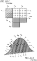
- the portions P 1 , P 2 , ... P n can form a pixelated surface. For simplicity, only one row of portions P 1 , P 2 , ... P n is shown in Figure 1A . However, certain embodiments can include additional rows and columns of portions P 1 , P 2 , ... P n .
- the portions P 1 , P 2 , ... P n can include a plurality of rows and columns spanning across the surface 12 of the master 10.
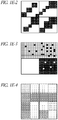
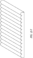
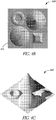
- FIG. 1B shows a 4x4 array of portions P 1 , P 2 , ... P n , the numbers of rows, columns, and portions P 1 , P 2 , ... P n are not particularly limited.
- borders 13 can surround at least part of the portions P 1 , P 2 , ... P n .
- the borders 13 can substantially surround a portion P n , or can surround just part of a portion P n .
- discontinuities can extend around all or substantially all of the portion P n .
- discontinuities may extend on just a part of the portion P n .
- the borders 13 can help define the size and shape of the portions P 1 , P 2 , ... P n in some embodiments.
- the size and shape of the portions P 1 , P 2 , ... P n are not particularly limited. For example, some of the portions P 1 , P 2 , ...
- the symmetrical shape can include a rectangle, a square, a rhombus, an equilateral triangle, an isosceles triangle, a regular polygon (e.g., a regular pentagon, a regular hexagon, a regular octagon, etc.), to name a few.
- the symmetrical shape can also include curvature, e.g., a circle, an ellipse, etc.
- some of the portions P 1 , P 2 , ... P n can comprise a non-symmetrical shape, e.g., a non-rotationally symmetrical shape, and/or an irregular shape.
- some of the portions P 1 , P 2 , ... P n can have a shape that is substantially the same as other portions P 1 , P 2 , ... P n . In some embodiments, at least 20%, at least 30%, at least 40%, at least 50%, at least 60%, at least 70%, at least 80%, at least 90% (or any range in between these percentages) of the portions P 1 , P 2 , ... P n can have the same shape, size, or both. In other embodiments, some of the portions P 1 , P 2 , ... P n can have a shape that is different from other portions P 1 , P 2 , ... P n .
- Arrangement of the portions P 1 , P 2 , ... P n is not particularly limited. For example, whether with or without borders, whether symmetrically shaped or non-symmetrically shaped, or whether regularly or irregularly shaped, the portions P 1 , P 2 , ... P n can form a periodic array. In other embodiments, whether with or without borders, whether symmetrically shaped or non-symmetrically shaped, or whether regularly or irregularly shaped, the portions P 1 , P 2 , ... P n can form an aperiodic array. In yet other embodiments, the portions P 1 , P 2 , ... P n can form a combination of periodic and aperiodic arrays.
- each portion P n can correspond to a point S 1 , S 2 , ... S n on the surface S of the 3D object 50, and each portion P n can include one or more features F 1 , F 2 , ... F n .
- the features F 1 , F 2 , ... F n shown in Figure 1A appear linear and substantially similar to each other.
- the features F 1 , F 2 , ... F n can vary in number, size, shape, and orientation.
- the features F 1 , F 2 , ... F n can include linear and/or curved features, for example as seen from a top or front view.
- the features F 1 , F 2 , ... F n can include facets, such as linear or curved saw tooth shaped features.
- the size of the features F 1 , F 2 , ... F n are not particularly limited. However, from a manufacturing and economic perspective, in some embodiments, a smaller height (e.g., 0 ⁇ m to 10 ⁇ m) can be advantageous to reduce the amount of material used. Accordingly, in some embodiments, the heights of the features F 1 , F 2 , ...
- F n can be from close to 0 ⁇ m to 0.1 ⁇ m (e.g., 0 nm to 100 nm, 1 nm to 75 nm, or 1 nm to 50 nm), from close to 0 ⁇ m to 1 ⁇ m (e.g., 0 nm to 1000 nm, or 1 nm to 500 nm), from close to 0 ⁇ m to 5 ⁇ m (e.g., 1 nm to 5 ⁇ m, 10 nm to 5 ⁇ m, 50 nm to 5 ⁇ m, 75 nm to 5 ⁇ m, 0.1 ⁇ m to 5 ⁇ m, 0.5 ⁇ m to 5 ⁇ m, or 1 ⁇ m to 5 ⁇ m), or from close to 0 ⁇ m to 8 ⁇ m (e.g., 1 nm to 8 ⁇ m, 10 nm to 8 ⁇ m, 50 nm to 8 ⁇ m, 75 nm to 8 ⁇ m, 0.1 ⁇
- the heights of the features F 1 , F 2 , ... F n can go up to 15 ⁇ m, up to 20 ⁇ m, up to 25 ⁇ m, or any ranges from 1 ⁇ m, 2 ⁇ m, or 3 ⁇ m up to 25 ⁇ m. In yet other embodiments, the heights of the features F 1 , F 2 , ... F n can go up to 50 ⁇ m if needed, e.g., depending on the desired size of the 3D image to be reproduced.
- the lateral dimensions of the features F 1 , F 2 , ... F n are not particularly limited, but can depend on the details of the 3D object.
- the lateral dimensions of the features F 1 , F 2 , ... F n can be less than 1 ⁇ m. Accordingly, the lateral dimensions of the features F 1 , F 2 , ...
- F n can be from close to 0 ⁇ m to 0.1 ⁇ m (e.g., 0 nm to 100 nm, 1 nm to 75 nm, or 1 nm to 50 nm), from close to 0 ⁇ m to 1 ⁇ m (e.g., 0 nm to 1000 nm, or 1 nm to 500 nm), from close to 0 ⁇ m to 5 ⁇ m (e.g., 1 nm to 5 ⁇ m, 10 nm to 5 ⁇ m, 50 nm to 5 ⁇ m, 75 nm to 5 ⁇ m, 0.1 ⁇ m to 5 ⁇ m, 0.5 ⁇ m to 5 ⁇ m, or 1 ⁇ m to 5 ⁇ m), or from close to 0 ⁇ m to 8 ⁇ m (e.g., 1 nm to 8 ⁇ m, 10 nm to 8 ⁇ m, 50 nm to 8 ⁇ m, 75 nm to 8 ⁇ m, 0.1 ⁇
- a lateral distance between two features can be defined in some embodiments as a pitch.
- the pitch between features within a portion P n can be substantially the same within the portion P n .
- the feature F 1 in portion P 1 of the portions P 1 , P 2 , ... P n , can comprise a plurality of features that form a periodic array such that the pitch is substantially the same within portion P 1 .
- the features F 1 , F 2 , ... F n among the multiple portions P 1 , P 2 , ... P n can form a periodic array such that the pitch is substantially the same among the portions P 1 , P 2 , ... P n .
- the features could be chirped and form an aperiodic array such that the pitch may be different among multiple portions P 1 , P 2 , ... P n .
- the pitch may be different for different portions P 1 , P 2 , ... P n
- the pitch can be slowly varying (e.g., less than 15% change per lateral distance, less than 12% change per lateral distance, less than 10% change per lateral distance, less than 8% change per lateral distance, less than 5% change per lateral distance, less than 3% change per lateral distance, or less than 1% change per lateral distance) among the portions P 1 , P 2 , ... P n .
- the pitch may uniformly change across multiple portions P 1 , P 2 , ... P n .
- the features could be chirped within a portion P n such that the pitch may be different within the portion P n .
- the pitch within the portion P n may slowly vary (e.g., less than 15% change per lateral distance, less than 12% change per lateral distance, less than 10% change per lateral distance, less than 8% change per lateral distance, less than 5% change per lateral distance, less than 3% change per lateral distance, or less than 1% change per lateral distance).
- the pitch may uniformly change with the portion P n .
- the pitch in certain embodiments can be between 1 ⁇ m and 100 ⁇ m, between 1 ⁇ m and 75 ⁇ m, between 1 ⁇ m and 50 ⁇ m, or between 1 ⁇ m and 25 ⁇ m.
- the features F 1 , F 2 , ... F n can correspond to elements E 1 , E 2 , ... E n on the optical product 10', and since the optical product 10' is configured to reproduce the 3D object 50, aspects of the features F 1 , F 2 , ... F n can correlate to aspects of the surface S of the 3D object 50 at the corresponding point S 1 , S 2 , ... S n .
- a gradient (e.g., slope) in the features F 1 , F 2 , ... F n can correlate to an inclination of the surface S of the 3D object 50 at the corresponding point S 1 , S 2 , ... S n .
- each feature can include a slope.
- a slope of the feature F 1 can correlate to the inclination of the surface S of the 3D object 50 at the corresponding point S 1 .
- the slope of the feature F 1 can correlate to the polar angle ⁇ 1 from reference line R 1 of the 3D object 50. Accordingly, the slopes of the features F 1 , F 2 , ... F n can mimic the surface normals of the 3D object 50.
- Various embodiments can advantageously have a uniform gradient (e.g., uniform slope) within each portion P n such that the gradient is a single value (e.g., a single polar angle ⁇ n ) at the corresponding point S n on the surface S of the 3D object 50.
- the feature F n within a portion P n includes a plurality of features, and the features within the portion P n may have more than one gradient (e.g., different slopes).
- the average gradient (e.g., average slope) of the features within the portion P n can correlate to the inclination of the surface S of the 3D object 50 at the corresponding point S n .
- varying the slopes within and/or among portions P 1 , P 2 , ... P n can create contrast on the surface and therefore, on the image 50'. Furthermore, varying at least one of the height of features, pitch between features (e.g., lateral distance between two features), and slope of the features in one or more portions P 1 , P 2 , ... P n can be used in authenticity and security applications. For example, one can intentionally vary the pitch within one or more portions P n , but maintain the given slopes. The image 50' of the 3D object 50 would be reproduced, yet upon closer inspection of the presence of the intentional variation within one or more portions P 1 , P 2 , ... P n , authenticity can be verified. Other variations are possible.
- the orientation of features F 1 , F 2 , ... F n can correlate to an orientation of the surface S of the 3D object 50 at the corresponding point S 1 , S 2 , ... S n .
- an orientation of the feature F 1 can correlate to the orientation of the surface S of the 3D object 50 at the corresponding point S 1 .
- the orientation of the feature F 1 can correlate to the azimuth angle ⁇ 1 from reference line R 2 of the 3D object 50.
- Various embodiments can advantageously have a uniform orientation within each portion P n , such that the orientation is a single value (e.g., a single azimuth angle ⁇ n ) at the corresponding point S n on the surface S of the 3D object 50.
- the feature F n within a portion P n includes a plurality of features, and the features within the portion P n may have more than one orientation (e.g., different orientations).
- the average orientation of the features within the portion P n can correlate to the orientation of the surface S of the 3D object 50 at the corresponding point S n .
- P n can slowly vary (e.g., less than 15% change per lateral distance, less than 12% change per lateral distance, less than 10% change per lateral distance, less than 8% change per lateral distance, less than 5% change per lateral distance, less than 3% change per lateral distance, or less than 1% change per lateral distance) within and among the portions P 1 , P 2 , ... P n .
- a feature F 1 includes multiple features within a portion
- the features can appear discontinuous with other features within the portion.
- the features F 1 , F 2 , ... F n can appear discontinuous with features in surrounding adjacent portions.
- the portions P 1 , P 2 , ... P n can form a single cell or a mono-cell.
- the features F 1 , F 2 , ... F n can appear continuous and smoothly varying depending on the shape.
- the features F 1 , F 2 , ... F n can appear discontinuous due to discontinuities in the 3D object 50.
- the features F 1 , F 2 , ... F n can comprise linear features corresponding to a substantially smooth region of the surface S of the 3D object 50.
- the features F 1 , F 2 , ... F n can also comprise non-linear features, e.g., curved features as seen from a top or front view, corresponding to a curved region of the surface S of the 3D object 50, e.g., instead of flat facets.
- features F 1 , F 2 , ... F n that are linear can be used to correspond to a curved region of the surface S of the 3D object 50.
- linear features on a master 10 can be used to represent a curved region by using a piecewise approximation function (e.g., a piecewise linear function such as a function comprising straight line sections).
- a piecewise approximation function e.g., a piecewise linear function such as a function comprising straight line sections.
- features F 1 , F 2 , ... F n that are non-linear can be used to correspond to a substantially smooth region of the surface S of the 3D object 50.
- non-linear features on a master 10 can be used to represent smooth regions on the surface S of the 3D object because the features F 1 , F 2 , ... F n can correspond to relatively small sized features on the optical product 10'.
- the pitch and/or texture on the optical product 10' can be from 1 ⁇ m to 100 ⁇ m, or any range within this range (e.g., from 1 ⁇ m to 75 ⁇ m, from 1 ⁇ m to 50 ⁇ m, from 1 ⁇ m to 25 ⁇ m, etc.).
- the features F 1 , F 2 , ... F n can correspond to aspects of the surface S of the 3D object 50 and can also correspond to elements E 1 , E 2 , ... E n on the optical product 10' such that the optical product 10' can reproduce an image 50' of the 3D object 50.
- the elements E 1 , E 2 , ... E n on the optical product 10' can be non-holographic.
- the elements E 1 , E 2 , ... E n do not need to rely on holography (e.g., effects based on diffraction and/or based on optical interference) to render a 3D image 50' of the 3D object 50.
- the features F 1 , F 2 , ... F n on the surface 12 of the master 10 can include non-sinusoidal features or non-quasi-sinusoidal features.
- sinusoidal or quasi-sinusoidal features can be diffractive with +/- orders of equal intensity that generate a twin image.
- One positive order and one negative order can share the incident light and result in a simultaneous twin image with counter-intuitive movement of one image with respect to the other.
- Such effects may be non-ideal.
- the features F 1 , F 2 , ... F n on the surface 12 of the master 10 can include other shapes, such as saw toothed shapes as described herein.
- some embodiments described herein do not necessarily rely on holography to reproduce an image, some embodiments can include diffractive or holographic features (e.g., less than or equal to 50% of the surface area, less than or equal to 40% of the surface area, less than or equal to 30% of the surface area, less than or equal to 20% of the surface area, less than or equal to 10% of the surface area, less than or equal to 5% of the surface area, less than or equal to 3% of the surface area, less than or equal to 2% of the surface area, or less than or equal to 1% of the surface area, or any range defined by any of these values) to be used in conjunction with the non-holographic elements E 1 , E 2 , ... E n described herein.
- diffractive or holographic features e.g., less than or equal to 50% of the surface area, less than or equal to 40% of the surface area, less than or equal to 30% of the surface area, less than or equal to 20% of the surface area, less than or equal to 10% of the surface area, less
- the second surface 12 of the master 10 can further comprise features corresponding to holographic elements on the optical product 10' in one or more portions P 1 , P 2 , ... P n .
- a holographic layer can be added over or under the surface 12' of the optical product 10'.
- Figure 1D is another example optical product 10' in accordance with certain embodiments described herein.
- the optical product 10' can include a plurality of portions P' 1 , P' 2 , ... P' n .
- Each portion P' n can include elements E 1 , E 2 , ... E n , e.g., non-holographic elements, on the optical product 10'.
- the elements E 1 , E 2 , ... E n can be embossed on the bottom surface of the substrate, e.g. UV curable resin having a refractive index of 1.5.
- the elements E 1 , E 2 , ... E n can be coated with a reflective coating.
- E n may then be embedded between the substrate and the item to which the optical product 10' is attached.
- the slopes of the elements E 1 , E 2 , ... E n can be configured to create the 3D depth perception of the image.
- elements E 1 , E 2 , ... E n with less steep slopes can cause light to reflect toward the observer's eye creating more brightness
- elements E 1 , E 2 , ... E n with steeper slopes can cause light to reflect away from the observer's eye creating more darkness.
- elements E 1 , E 2 , ... E n with steep enough slopes can cause light to be totally internally reflected within the substrate (which has a higher index than the surrounding medium), and creating even more darkness.
- Figure IE is another example optical product 10' in accordance with certain embodiments described herein.
- the optical product 10' can include a plurality of portions P' 1 , P' 2 , ... P' n .
- Each portion P' n can include elements E 1 , E 2 , ... E n , e.g., non-holographic elements, on the optical product 10'.
- utilizing embodiments of the optical product 10' having elements E 1 , E 2 , ... E n (or masters having features F 1 , F 2 , ... F n ) with smaller height can be advantageous to reduce the amount of material used.
- certain embodiments can utilize elements E 1 , E 2 , ...
- the number of substantially contiguous portions can include at least two, three, four, five, eight, ten, fifteen, twenty, or more, or be in any range in between these values.
- a master 10 are configured to fabricate an optical product 10'.
- the optical product 10' can be configured, when illuminated, to reproduce (e.g., by reflected or transmitted light) a 3D image 50' of at least a part of a 3D object 50.
- the master 10 or optical product 10' can include features F 1 , F 2 , ... F n or elements E 1 , E 2 , ... E n .
- such features F 1 , F 2 , ... F n or elements E 1 , E 2 , ... E n can include specular reflecting features and diffusing features that can provide greyscale in the 3D image 50'.
- the specular reflecting and diffusing features can be provided by a diffuser coated with a reflective material.
- the diffuser can include a micro diffuser (e.g., a tailored micro diffuser).
- a micro diffuser e.g., a tailored micro diffuser.
- Some such diffusers can be fabricated from polymer materials for example, polyethylene terephthalate (PET), oriented polypropylene (OPP), low density polyethylene (LDPE), linear low density polyethylene (LLDPE), polypropylene (PP), polyvinyl chloride (PVC), polycarbonate (PC), etc.
- PET polyethylene terephthalate
- OPP oriented polypropylene
- LDPE low density polyethylene
- LLDPE linear low density polyethylene
- PP polypropylene
- PVC polyvinyl chloride
- PC polycarbonate
- the polymer materials can have a pseudo-random distribution or a tailored distribution of diffusing features.
- the diffuser can be coating with a reflective material such as aluminum, silver, gold, copper, titanium, zinc, tin, or alloys thereof (e.g.,
- the diffuser has a surface that can receive incident light rays, and can break up an incident ray angle into many angles with a random or a tailored distribution over a wide angle.
- the shape of the scattered light angular distribution e.g., Bi-Directional Reflectance Distribution Function or BRDF
- BRDF Bi-Directional Reflectance Distribution Function
- the surface of the diffuser may not completely scatter the light.
- some such surfaces can have diffusing features (e.g., features that can scatter light) and specular reflecting features (e.g., features that do not scatter light).
- an optical product 10' can utilize specular reflecting features and diffusing features to vary the brightness (or darkness, e.g., greyness) in a 3D image.
- Various embodiments utilizing such variation can result in enhanced contrast in the image compared to embodiments not utilizing specular reflecting features and diffusing features.
- the slopes of optical features F 1 , F 2 , ... F n in various portions P 1 , P 2 , ... P n can create depth perception and contrast in a 3D image as described herein. For example, less steep slopes can cause light to reflect toward the observer's eye, while steeper slopes can cause light to reflect away from the observer's eyes.
- F n having specular reflecting features and diffusing features can provide additional contrast in the 3D image.
- macro features e.g., F 1 , F 2 , ... F n
- micro features e.g., specular reflecting features and diffusing features
- the amount of specular reflecting features and diffusing features can be varied in the various portions P 1 , P 2 , ... P n to control the brightness (or the darkness, e.g., greyness) of an image.
- the brightness (or darkness, e.g. greyness) as perceived by a viewer of an area can be modulated by the ratio of specular reflecting features to diffusing features.
- the brightness (or darkness, e.g. greyness) as perceived by a viewer of an area within a portion can be modulated by the ratio of the area (e.g., area of the footprint) of specular reflecting features to the area (e.g., area of the footprint) of the diffusing features.
- the size, number, and/or distribution of the specular reflecting features relative to the size, number, and/or distribution of the diffuse reflecting features in an area within a portion can likewise be configured to provide the level of brightness, darkness, (e.g., greyness).
- the images produced can be achromatic.
- the specular reflecting features and diffusing features can provide no diffractive or interference color (e.g., no wavelength dispersion or rainbows or rainbow effects).
- Pigment, inks, or other absorptive material can be used to provide color, in which case the relative areas, size, number, and/or distribution of the specular reflecting features relative to that of the diffuse reflecting features would control the perceived brightness or darkness of the hue or color.
- the level of brightness, darkness can be provided by the size and/or number of the specular reflecting features relative to the size and/or number of the diffusing features.
- the size and/or number of the specular reflecting and diffusing features can be based on a height and/or width of a top surface (e.g., a flat top surface) of the specular reflecting and diffusing features.
- Such sizes and/or number can be provided by height (and/or depth) modulation as will be discussed in relation to Figures 1E-1a, 1E-1b, 1E-1c, and 1E-1d .
- Figures 1E-1a, 1E-1b, 1E-1c, and 1E-1d show an example of height modulation to vary the ratio of specular reflecting features to diffusing features in accordance with various embodiments described herein.
- Figure 1E-1a schematically illustrates a cross section of a surface having 100% diffusing features and 0% specular reflecting features. In this example, the distribution of the surface feature heights or widths (or a combination thereof) is random.
- FIG. 1E-1b schematically illustrates a surface having 0% diffusing features and 100% specular reflecting features. The dashed line indicates a reflective coating.
- the ratio between specular reflecting features and diffusing features can be modulated.
- the ratio between such features can correlate to a level of grey or brightness/darkness of hue if colored (e.g., including a tint, an ink, dye, or pigment where absorption can provide color).
- Utilizing a different ratio between such features in various portions P 1 , P 2 , ... P n of certain embodiments can produce varying levels of grey or brightness/darkness in the produced image.
- certain embodiments can reproduce a black and white image including many shades of grey (or many levels of brightness/darkness of hue if colored).
- the shape of the specular reflecting features and diffusing features for example, in the area (e.g., area of the footprint) may be square, rectangular, hexagonal, circular, or a wide variety of other shapes.
- the specular reflecting features and diffusing features may be packed together in a wide variety of arrangements, e.g., in a square array, triangular array, hexagonally closed packed, or in other arrangements.
- half-tone patterning or greyscale can be used to control the brightness (or the darkness, e.g., greyness) of an image.
- Figure 1E-2 schematically illustrates an example half-tone pattern or screen that can be used in certain embodiments described herein.
- the black areas can represent the specular reflecting features (or the diffusing features)
- the white areas can represent the diffusing features (or the specular reflecting features). Varying the size, number, and/or distribution of the specular reflecting features relative to the size, number, and/or distribution of the diffuse reflecting features can be used to provide greyscale (or brightness/darkness of hue) in the produced image.
- the exact pattern or screen is not particularly limited and can vary according to the desired size, number, and/or distribution.
- a minimum half-tone feature in the half-tone patterning can be less than or equal to 75 microns (e.g., less than or equal to 65 microns, less than or equal to 50 microns, less than or equal to 30 microns, less than or equal to 10 microns, etc.) and/or be in a range from 0.05 micron to 75 microns (e.g., 0.05 micron to 65 microns, 0.05 micron to 50 microns, 0.05 micron to 30 microns, 0.05 micron to 10 microns, 1 micron to 75 microns, 1 micron to 50 microns, etc.).
- Figure 1E-3 schematically illustrates another example half-tone pattern and/or screen that can be used in certain embodiments described herein.
- the black areas can represent the specular reflecting features (or the diffusing features), and the white areas can represent the diffusing features (or the specular reflecting features).
- a single image pixel can be broken into a grid of sub-pixels. To achieve 100 levels of grey, the grid can be provided as 10 x 10 subpixels. To achieve 50% grey, half of the subpixels represent specular reflecting features, and the remaining subpixels represent diffusing features.
- the distribution of the subpixels can be a pattern, a screen, and/or a stochastic dither (e.g., a pseudo-random probability distribution) as shown in Figure 1E-3 .
- the stochastic dither can be applied to a spatial distribution of a fixed-pattern diffuser and reflective subpixels, or the stochastic dither can be applied in three dimensions to accompany variable height or pattern diffusers.
- the exact dither is not particularly limited and can vary according to the desired size, number, and/or distribution.
- the black areas can represent 100% specular reflecting features (or 100% diffusing features), and the white areas can represent 100% diffusing features (or 100% specular reflecting features).
- Figure 1E-4 schematically illustrates an example greyscale that can be used in certain embodiments described herein. In some such embodiments the levels of specular reflecting features and diffusing features can be in between 0% and 100% (e.g., 30%, 70%, etc.). For example, as discussed above with regard to Figures 1E-1a, 1E-1b, 1E-1c, and 1E-1d , different levels of grey can be provided by different levels of specular reflecting features and diffusing features.
- Figure 1E-4 shows an example pixel having 4 cells (e.g., 4 quandrants). There are four possible levels of grey within four cells per pixel. Accordingly, there are 16 possible levels per cell or 64 possible levels per pixel. The exact greyscale is not particularly limited and can vary according to the desired representation.
- various embodiments of the optical product 10' can be advantageously used for authenticity and security applications.
- a recent trend has been to make the holograms used for authenticity and security applications more complicated.
- a disadvantage of using complicated holograms authenticity and security applications is that an average person may be unable to remember what the image is supposed to be. Thus, even if it were possible to make counterfeit copies of such complicated holograms the average person may not be able to distinguish a genuine hologram from the counterfeit hologram from the holographic image alone.
- Embodiments of the optical object 10' can include a plurality of optical features that can produce different distinct images when viewed from different directions. Such a configuration can be resistant to photocopying, laser playback into a photoresist from bouncing the beam off of the plurality of optical features to form an original master, or other methods for duplicating. Thus, such objects can be suitable for security and/or authenticity applications. Additionally, the methods and system to manufacture various embodiments of optical objects described herein may not be easily practiced by counterfeiters thus reducing the risk of counterfeiters having the ability to make counterfeit copies of the optical object.
- the different distinct images produced by the plurality of optical features included in the various embodiments of optical objects 10' described herein can be viewed from a variety of different viewing directions and can be brightly reflecting.
- Such embodiments can be advantageous over objects used in security applications that incorporate optically variable inks and/or magnetic optically variable inks which can have reduced brightness thus making them difficult to see under low light conditions.
- currency notes including embodiments of optical objects including a plurality of optical features that are configured to produce different distinct images when viewed from different directions can be brighter and more resistant to counterfeiting than currency notes that do not include such optical features and instead rely on optically variable inks and/or magnetically optically variable inks and pigments, which have been used in the banknote industry.
- Figures 1F-1, 1F-2 , 1G-1 and 1G-2 schematically illustrate top views of an optical product 10' including a first plurality of portions, each of the first plurality of portions comprising one or more optical features that are configured to produce at least part of a first 3D image of a first 3D object at a first angle of view.
- the optical product 10' also includes a second plurality of portions, each of the second plurality of portions comprising one or more optical features that are configured to produce at least part of a second 3D image of a second 3D object at a second angle of view.
- Each portion of the optical product 10' can also be referred to as a pixel or a tile.
- the optical product 10' can be configured to produce a first distinct image (e.g., a text, such as, for example, the number "100") when viewed from a first direction and a second distinct image (e.g., an object, such as, for example a bell) when viewed from a second direction.
- the optical object 10' can be configured such that the first plurality of portions comprise a first set of optical features that contribute to producing the first 3D image and the second plurality of portions comprise a second set of optical features that contribute to producing the second 3D image.
- Figures 1F-1 and 1F-2 schematically illustrate top view of an embodiment of an optical object 10' that comprises a first plurality of portions P A1 , P A2 and P A3 .
- Each of the first plurality of portions P A1 - P A3 comprises a first set of optical features F 1 configured to produce a first distinct image when viewed from a first direction.
- the optical object 10' also comprises a second plurality of portions P B1 - P B3 that comprise a second set of optical features F 2 that are configured to produce a second distinct image when viewed from a second direction.
- Figure 1G-1 schematically illustrates an embodiment of an optical object 10' that comprises a first plurality of portions P A1 , P A2 , P A3 , P A4 and P A5 .
- Each of the first plurality of portions P A1 - P A5 comprises a first set of optical features F 1 which together are configured to produce a first distinct image when viewed from a first direction.
- the illustrated embodiment also comprises a second plurality of portions P B1 , P B2 , P B3 and P B4 .
- Each of the second plurality of portions P B1 - P B4 comprises a second set of optical features F 2 which together are configured to produce a second distinct image when viewed from a second direction.
- the optical features in each of the first plurality of portions can produce a part of the first image of the first 3D object.
- the first and the second plurality of portions can be interspersed.
- the first plurality of portions P1 and the second plurality of portions P2 are interspersed with each to form a checker board pattern. Other patterns and distributions are also possible.
- Figure 1G-2 schematically illustrates a top view of an embodiment of an optical object 10' that comprises a first plurality of portions (e.g., P A1 , P A2 ) including one or more optical features F 1 and a second plurality of portions (e.g., P B1 , P B2 , P B3 ) including one or more optical features F 2 .
- a first plurality of portions e.g., P A1 , P A2
- a second plurality of portions e.g., P B1 , P B2 , P B3
- the optical features F 1 in the first plurality of portions together contribute to produce a first image (e.g., text "100") when viewed from a first direction and the optical feature F 2 in the second plurality of portions (e.g., P B1 , P B2 , P B3 ) together contribute to produce a second image (e.g., liberty bell) when viewed from a second direction.
- a first image e.g., text "100”
- the optical feature F 2 in the second plurality of portions e.g., P B1 , P B2 , P B3
- a second image e.g., liberty bell
- each of the plurality of portions can be of equal size or shape. Alternately, in other embodiments, some of the plurality of portions can have a different size than some other of the plurality of portions.
- the optical features F 1 and F 2 can comprise linear or curved grooves, facets, or other surface relief features. In various embodiments, the optical features F 1 and F 2 can have a curved cross-sectional shape.
- the orientation, slope/gradient and other physical attributes of the optical features F 1 and F 2 are configured such that the intensity of light reflected and/or transmitted through the optical object 10' from the optical features F 1 and F 2 is varied to form regions of varying brightness and darkness which results in the perception of different images when viewed from different directions.
- the different sets of optical features can be configured such that light that is retro-reflected appears bright and light reflected at different angles appears black or different shades of grey to give depth perception. This is described in detail with reference to Figure 1H as well as elsewhere herein.
- Figure 1H schematically illustrates an enlarged side view of a portion of an optical product 10' including a plurality of optical features that are configured to produce different distinct images when viewed from different directions.
- the first set of optical features F 1 is represented by solid line and the second set of optical features F 1 is represented by dashed line.
- the physical attributes of the first set of optical features F 1 such as, for example, slope/gradient, orientation is varied such that when the optical object 10' is oriented such that a viewer viewing the optical object 10' along a first direction ⁇ 1 perceives a first image (e.g., the text "100").
- the physical attributes of the second set of optical features F 2 such as, for example, slope/gradient, orientation, is varied such that when the optical object 10' is oriented such that a viewer viewing the optical object 10' along a second direction ⁇ 2 perceives a second image (e.g., a bell).
- the first and the second viewing directions can be oriented (e.g., tilted and/or rotated) with respect to each other by an angle from 10 degrees to 60 degrees.
- the viewer can switch (or flip) between viewing the first and the second image by tilting the optical object 10' by an angle from 10 to 60 degrees (e.g., 20 degrees or less) about an axis in the plane of the optical object 10'.
- the optical object 10' is configured as a transmissive embodiment, the viewer can switch (or flip) between the first and the second image by rotating the optical object 10' by an angle from 10 to 60 degrees (e.g., 45 degrees or less).
- the optical object 10' can include laminates, films, or layers.
- the optical object 10' can be manufactured using the methods described herein.
- the physical attributes e.g., orientation, slope/gradient
- the different sets of optical features can be determined using an algorithm that can be executed by an electronic processing system and stored in a data file.
- the different sets of optical features can be disposed on a polymeric substrate using one or more positive/negative masters.
- reflective material e.g., aluminum, copper, silver, high refractive index material, such as, for example, ZnS or TiO 2 for TIR
- ZnS or TiO 2 for TIR can be disposed on the plurality of optical features.
- the optical object 10' can be reflective or transmissive.
- the optical object 10' can be partially reflective or partially transmissive. For example, if the thickness of the reflective material is greater than or equal to 45 nm (e.g., 50 nm, 55 nm, 60 nm, etc.) and/or be in a range from 45 nm to 100 nm, or any range within this range (e.g., from 45 nm to 85 nm, from 45 nm to 75 nm, from 50 nm to 85 nm, etc.), then the optical object 10' can be reflective.
- 45 nm e.g., 50 nm, 55 nm, 60 nm, etc.
- the optical object 10' can be reflective.
- the thickness of the reflective material is less than 45 nm (e.g., 10 nm, 15 nm, 20 nm, 25 nm, etc.) and/or be in a range from 10 nm to 44.9 nm, or any range within this range (e.g., from 10 nm to 40 nm, from 10 nm to 35 nm, from 10 nm to 30 nm, etc.), then the optical object 10' can be transmissive.
- the thickness of the reflective material at which the optical object 10' is reflective or transmissive can depend on the chemical composition of the reflective material.
- the plurality of optical features coated with the reflective material can be protected by a protective polymer coating.
- Figure 1I illustrates an embodiment of the optical object 10' comprising a plurality of optical features F 1 and F 2 disposed on a polymeric substrate 1005.
- the polymeric substrate 1005 can include materials, such as, for example, polyethylene terephthalate (PET), oriented polypropylene (OPP), low density polyethylene (LDPE), linear low density polyethylene (LLDPE), polypropylene (PP), polyvinyl chloride (PVC), polycarbonate (PC) or any other plastic film.
- PET polyethylene terephthalate
- OPP oriented polypropylene
- LDPE low density polyethylene
- LLDPE linear low density polyethylene
- PP polypropylene
- PVC polyvinyl chloride
- PC polycarbonate
- the polymeric substrate can be clear.
- the polymeric substrates can have a thickness less than or equal to 25 microns.
- the physical attributes of the plurality of optical features F 1 and F 2 can be determined from input images that correspond to the images that are desired to be perceived by a viewer.
- the input images can be three dimensional (3D) images.
- the input images can be dot matrix images.
- the physical attributes of the plurality of optical features F 1 and F 2 that will produce the desired images when illuminated by light can be determined using processes and algorithms that are executed by an electronic processing system.
- the processes and algorithms can be configured to analyze the input images and determine physical attributes (e.g., orientation, slope/gradient) of the different sets of optical features.
- the processes and algorithms can be based on equations and phenomena that govern the interaction of light with matter.
- the plurality of optical features F 1 and F 2 are coated with a thickness of a reflective material 1010.
- the optical object 10' can be reflective or transmissive.
- a protective covering 1015 is disposed over the reflective material coating 1010 to protect the plurality of the optical features F 1 and F 2 and/or the reflective material coating 1010 from corrosion from acidic or basic solutions or organic solvents such as gasoline and ethyl acetate or butyl acetate.
- the protective covering 1015 can also provide protection during subsequent processing steps of the object like manufacturing currency.
- the plurality of optical features F 1 and F 2 can be integrated with one or more lenses (e.g., a curved lens or a Fresnel lens or a lenticular lens) and/or prisms and/or mirrors.
- the focal length of the lens can be approximately equal to the thickness of polymeric substrate 1005.
- Some such embodiments can present images with higher contrast and sharpness than some embodiments without lenses and/or prisms and/or mirrors.
- certain embodiments described herein, e.g., referring to Figures 1F-1 and 1F-2 for example, are configured to produce by reflected or transmitted light, two distinct images when viewed from different directions.
- the slopes of the optical features F 1 , F 2 within the various portions P An , P Bn can create depth perception and contrast in the 3D images as described herein.
- the slopes of the optical features F 1 , F 2 can also separate the two distinct images to avoid cross talk and allow the observer to view the images independently from each other at a viewing angle. For example, less steep slopes can cause light to reflect toward the observer's eye, while steeper slopes can cause light to reflect away from the observer's eye.
- the full tilt range would not be used to create the contrast in the images.
- Figure 1J-1 schematically illustrates an isometric view of an example optical product 1000 including an array 1025 of lenses disposed over a plurality of portions P An , P Bn (e.g., having optical features as described herein).
- the optical product 1000 shown in Figure 1J-1 is configured to present different distinct images when viewed from different directions.
- the array 1025 of lenses can present a first 3D image (e.g., text "100").
- the array 1025 of lenses can present a second 3D image (e.g., liberty bell).
- an array of prisms or an array of mirrors can be used in combination with or instead of the lenses.
- Figure 1J-2 schematically illustrates an example optical product including an array of prisms.
- the array 1025 of lenses and/or prisms and/or mirrors can be configured to separate the two distinct images so that the images can be viewed independently of each other. Because the lenses and/or prisms and/or mirrors can separate the images, the full tilt range of the optical features F 1 , F 2 can be used to create contrast and sharpness in the images.
- the array 1025 of lenses can include a 1D lens array. As shown in Figure 1J-3 , the lenses can extend in length much longer than shown in Figure 1J-1 . However, the drawings and schematics are merely illustrative. A wide variation in sizes and dimensions are possible.
- the array 1025 of lenses can include a number of cylindrical, hemi-cylindrical lenses, truncated hemi-cylindrical lenses, or piano convex cylindrical lenses with one convex surface and one piano surface. In some embodiments, the lenses can have one convex surface and one concave surface.
- the array of lenses can include a micro lens array having a pitch (e.g., lateral distance between the centers of two lenses) from 8 microns to 300 microns (such as 8 microns, 12 microns, 15 microns, 20 microns, 25 microns, 30 microns, 42 microns, 50 microns, 62.5 microns, 75 microns, 87.5 microns, 100 microns, 125 microns, 150 microns, etc.) or any ranges within this range (such as 8 microns to 250 microns, 8 microns to 200 microns, 12.5 microns to 250 microns, 30 microns to 300 microns, 30 microns to 250 microns, 62.5 microns to 187.5 microns, 62.5 microns to 175 microns, 62.5 microns to 162.5 microns, 75 microns to 187.5 microns, etc.).
- the pitch can be constant across the array 1025 of lenses. However, in some embodiments, the
- a lens within the array 1025 of lenses can have a width W L (e.g., along the x-axis).
- the width W L of a lens can be the same as the values of pitch described herein.
- the width W L of a lens can be the same as the width W L of another lens in the array 1025 of lenses.
- the width W L of a lens can be different than the width W L of another lens in the array 1025 of lenses.
- the radius of curvature of a lens can be from 10 microns to 500 microns (such as 10 microns, 15 microns, 37.5 microns, 50 microns, 62.5 microns, 75 microns, 87.5 microns, or 100 microns) or any ranges within this range (such as 10 microns to 87.5 microns, 10 microns to 75 microns, 37.5 microns to 87.5 microns, 37.5 microns to 75 microns, 50 microns to 87.5 microns, 50 microns to 75 microns, etc.).
- the radius of curvature of a lens can be different from the radius of curvature of another lens in the array 1025 of lenses.
- the curvature can be rotationally symmetrical or can be rotationally asymmetrical.
- the radius of curvature of the lens can be greater than 500 microns.
- Some embodiments may comprise freeform lenslets instead of rotationally symmetric lenslets.
- the lenses can be made of various materials such as a polymer.
- the array 1025 of lenses can be UV casted into a resin layer coated on a polymer substrate.
- substrate materials can include, but are not limited to, polyethylene terephthalate (PET), oriented polypropylene (OPP), low density polyethylene (LDPE), linear low density polyethylene (LLDPE), polypropylene (PP), polyvinyl chloride (PVC), or polycarbonate (PC).
- PET polyethylene terephthalate
- OPP oriented polypropylene
- LDPE low density polyethylene
- LLDPE linear low density polyethylene
- PP polypropylene
- PVC polyvinyl chloride
- PC polycarbonate
- the array 1025 of lenses can be molded or embossed in a polymer substrate.
- Moldable and/or embossable substrates can include acrylonitrile butadiene styrene (ABS), polymethyl methacrylate (PMMA), polyethylene (PE), polycarbonate/acrylonitrile butadiene styrene (PC/ABS), and polyethylene terephthalate glycol-modified (PETG).
- ABS acrylonitrile butadiene styrene
- PMMA polymethyl methacrylate
- PE polyethylene
- PC/ABS polycarbonate/acrylonitrile butadiene styrene
- PETG polyethylene terephthalate glycol-modified
- a lens can have a focal length (and corresponding f-number) and be disposed at a distance with respect to the back side of the substrate in comparison to the lens's focal length to focus light on the back side of the substrate.
- a lens can have a focal length (and corresponding f-number) and be disposed at a distance with respect to the back side of the substrate in comparison to the lens's focal length to focus light on the front side of the substrate.
- a lens can have a focal length (and corresponding f-number) and be disposed at a distance with respect to the back side of the substrate in comparison to the lens's focal length to focus light in between the front and back sides of the substrate.
- Example focal lengths include a number from 10 microns to 300 microns (such as 10 microns, 12.5 microns, 15 microns, 30 microns, 37.5 microns, 62.5 microns, 75 microns, 87.5 microns, 100 microns, 112.5 microns, 125 microns, 137.5 microns, 150 microns, 162.5 microns, 175 microns, 187.5 microns, 200 microns, etc.) or any ranges within this range (such as 10 microns to 250 microns, 12.5 microns to 250 microns, 12.5 microns to 200 microns, 37.5 microns to 187.5 microns, 37.5 microns to 175 microns, 62.5 microns to 187.5 microns, 62.5 microns to 175 microns, etc.).
- the focal length (and f-number) of a lens can be different from the focal length (and f-number) of another lens in the array 1025
- the array 1025 of lenses is illustrated in Figure 1J-1 as a 1D array of lenses, in some embodiments, the array 1025 of lenses can include a 2D array of lenses.
- Figure 1J-4 shows an example 2D array of lenses.
- a 1D array of lenses e.g., Figure 1J-3
- a 2D array of lenses e.g., Figure 1J-4
- the 2D array comprises lenses having surfaces that are rotationally symmetric surfaces.
- the 2D array can comprise lenses having surfaces that are asymmetrical.
- the lenses can be elliptical in that the lenses are longer in one orthogonal direction compared to the other.
- the shape and or arrangement of the lenses should not be considered to be limited.
- the surfaces of the lenses can be convex, aspherical, toroidal, and/or de-centered.
- the lenses may have circular, square, rectangular, hexagonal aperture shape or footprint, or may have other shapes, and the aperture may be truncated.
- the lenses may be arranged in a square array, triangular array, hexagonal closed packed, or arranged otherwise.
- the array 1025 of lenses can include a series of lenses (e.g., a lenticular lens) configured to allow the features disposed under the lenses corresponding to different images to be viewable at different viewing angles.
- the lenses are magnifying lenses to enlarge different features disposed under the lenses corresponding to different images at different viewing angles.
- the lenses can provide an avenue to switch between different images through different channels.
- the product 1000 can include a first set of portions P A and a second set of second portions P B disposed under the array 1025 of lenses.
- the first plurality of portions P A and the second plurality of portions P B are interlaced with each other.
- the array 1025 of lenses can be configured to allow the first image (e.g., text "100") to be viewable without allowing the second image (e.g., liberty bell) to be viewable.
- the array 1025 of lenses can be configured to allow the second image (e.g., liberty bell) to be viewable without allowing the first image (e.g., text "100") to be viewable.
- the array 1025 of lenses can switch between the two images.
- the first plurality of portions P A and the second plurality of portions P B can be disposed under the array 1025 of lenses.
- the first plurality of portions P A and the second plurality of portions P B can have a width w smaller than the width W L of a lens in the array 1025 of lenses.
- a pair of a first plurality of portions P A and a second plurality of portions P B can be aligned under each lens in the array 1025 of lenses.
- a pair of a first plurality of portions P A and a second plurality of portions P B need not be exactly aligned under a single lens in the array 1025, but might be offset from such an alignment.
- a first plurality of portions P A can be disposed under a single lens in the array, while a portion of plurality of portions P B can be disposed under parts of two different lenses in the array 1025.
- the pairs of a first plurality of portions P A and a second plurality of portions P B under the array 1025 of lenses are not alignment sensitive (e.g., exact alignment of pairs of a first plurality of portions P A and a second plurality of portions P B under a single lens in the array 1025 is not necessary).
- a lens within the array 1025 of lenses can be registered on average to a pair of a first plurality of portions P A and a second plurality of portions P B .
- a lens can correspond to a pair of a first plurality of portions P A and a second plurality of portions P B .
- Light from a first portion P A1 can pass through a first part of a lens and light from a second portion P B1 and a second plurality of portions P B1 can pass through a separate part of the lens, and corresponding portions of the lens can form the images 110, 120 at two different angles as described herein.
- most of the lens may be registered with respect to the pair of a first plurality of portions P A and a second plurality of portions P B .
- Figure 1J-5 illustrates a cross-sectional view of an embodiment of an optical product 1060A comprising a carrier 1065 and a portion P' 1 including a plurality of optical features (e.g. F' 1 ) that are configured to produce an image of an object or part thereof.
- the optical product 1060A can have features/characteristics that are similar to the optical product 10' discussed above.
- a reflective material can be disposed over the portion P' 1 .
- the portion P' 1 can be formed on a substrate and disposed on the first side of the carrier 1065.
- the carrier 1065 can have characteristics similar to the various polymeric substrates (e.g., polymeric substrate 1005 of Figure 1I ) described herein.
- the carrier 1065 can comprise a polymeric material having a refractive index greater than the refractive index of air.
- Light rays that are incident on the carrier 1065 after being reflected and/or scattered by the plurality of optical features at angles less than the critical angle of the material of the carrier 1065 as measured with respect to a normal to the surface, such as, for example, close to the normal to the surface of the carrier 1065 can exit out of the carrier 1065 as shown in Figure 1J-5 .
- high angle rays that are incident on the carrier 1065 after being reflected and/or scattered by the plurality of optical features at angles greater than the critical angle of the material of the carrier 1065 will be total internally reflected and do not exit out of the carrier 1065 as shown in Figure 1J-5 . Accordingly, the image generated by the plurality of optical features of the product 1060A can only be viewed over an angular range that is less than the critical angle.
- a lens element 1068 can be disposed on a second side of the carrier 1065 and registered with the portion P' 1 to increase the angular range over which the image produced by the plurality of optical features can be viewed.
- the lens element 1068 can be a part of an array of lenses. The lenses in the array can be on average registered with the plurality of portion P n '.
- the lens element 1068 can advantageously increase the viewing angle over which the image generated by the portion P' 1 can be viewed, in part due to the condition of total internal reflection of high angle rays not being satisfied as explained below with reference to Figures 1J-5 and 1J-6 .
- the lens element 1068 can have a curved surface which can reduce the angle between the high angle rays and the surface normal such that the condition for total internal reflection is not satisfied.
- the lens element 1068 can be optically transmissive. Accordingly, some of the high angle rays that are incident on the carrier 1065 after being reflected and/or scattered by the plurality of optical features can exit out of the carrier 1065 instead of being total internally reflected. Consequently, the product 1060B including a lens element 1068 can advantageously increase the view angle over which the image produced by the plurality of optical features can be viewed.
- the lens element 1068 can also provide other advantages including but not limited to improving focus of the different images, increasing the difference between the tilt angles at which the different images can be viewed (also referred to as tilt budget) for embodiments in which multiple sets of portions produce multiple images, increasing depth perception by allowing a viewer to receive light at steeper angles and other advantages discussed herein.
- the lens element 1068 can increase the range of local surface normal as shown in Figure 1J-7 .
- Figure 1J-7 For example, consider rays of light that are emitted from different points of the surface of the facet along a normal direction as illustrated in Figure 1J-7 . Each of the rays will be refracted out of the lens element 1068 in various directions depending on the curvature of the lens element at the point where each of the normal rays of light intersects the lens element. In this manner, the angular range of rays that are emitted along a normal direction to the surface is expanded.
- the lens element 1068 can be lenticular in some embodiments.
- the lens element 1068 can be, a spherical lens and/or a rotationally symmetric aspheric lens. In some embodiments, the lens element 1068 can be a part of a 1-D array of lenses as shown in Figures 1J-3 . In some other embodiments, the lens element 1068 can be a part of a 2-D array of lenses as shown in Figure 1J-4 . In some embodiments, the lens element 1068 can be a microlens.
- the array of lenses can be a rectangular array, a square array, a triangular array, a hexagonal close packed array or an irregular array.
- individual lenses of the array 1025 of lenses can be disposed over a plurality of portions P An , P Bn (e.g., having optical features as described herein) that are configured to produce a plurality of images or parts thereof.
- an individual lens of the array 1025 of lenses can be disposed over at least a first plurality of portions P A configured to produce image A and a second plurality of portions P B configured to produce image B.
- the first plurality of portions P A can be configured to produce a first image or part thereof and the second plurality of portions P B can be configured to produce a second image or part thereof.
- the array 1025 of lenses can be configured such that a viewer may be able to view the first or the second image by flipping or tilting the product 1080 about an axis as discussed above with reference to Figure 1J-1 .
- the array 1025 of lenses disposed over the plurality of portions P An , P Bn having different sets of optical features as described herein with reference to Figure 1J-1 can also provide the advantage of increased field of view and other advantages discussed above.
- the first image produced by the first plurality of portions P A can correspond to a first stereoscopic version of an image corresponding to a right eye perspective of the an object and the second image produced by the second plurality of portions P B can be configured to produce a second stereoscopic version of an image corresponding to a left eye perspective of the object.
- the lenses of the array 1025 of lenses can be configured to direct light from the first plurality of portions P A towards the right eye of a viewer and light from the second plurality of portions P B towards the left eye of the viewer thereby generating 3D images (e.g., autostereoscopic images) which produce the perception of depth.
- optical features, such as are described herein, included in the plurality of portions P An , P Bn can have facets that are tilted progressively as depicted in the inset of Figure 1J-8 which illustrates a cross-sectional view along axis X-X' of one of the second plurality of portions P B .
- the array of optical element e.g., lenses, prisms or mirrors
- the array of optical element can be integrated or combined together in one surface with the optical features that are included in the plurality of portions P An , P Bn (e.g., having optical features as described herein) that are configured to produce a plurality of images or parts thereof.
- Figure 1J-9 illustrates a cross-sectional view of a product 1085 comprising a first plurality of portions P A1 , P A2 , ... P An .
- Each portion P An can include optical features (e.g., optical features F 1 , F 2 , ..., F n ) or facets that can produce a first image.
- the product 1085 also includes a second plurality of portions P B1 , P B2 , ... P Bn which produce a second image.
- the second plurality of portions P B1 , P B2 , ... P Bn which are illustrated in the bottom view of the product 1085 shown in Figure 1J-10 .
- the carrier can include a plurality of portions configured to produce at least a first image of a first object and a second image of the second product.
- the combined surface 1095 of the plurality of portion combined with the optical elements is illustrated in Figure 1J-10 .
- Various embodiments, can include a plurality of elongate cylindrical lenses or mirrors 1097 that extend over the multiple portions as depicted in Figure 1J-11 instead of the plurality of optical elements 1090.
- the surfaces of the optical features or facets can be slowly varying (e.g., sloped) such that the surface across some or all plurality of portions P A1 , P A2 , ... P An is substantially continuous as discussed above with reference to Figure IE.
- the product 1085 further comprises optical elements 1090 such as lenses, prisms or mirrors (e.g., curved mirrors) integrated (e.g., monolithically integrated) with the optical features or facets.
- the optical elements 1090 can include powered elements such as lenticular elements, microlenses, concave mirrors, cylindrically shaped concave mirrors, rotationally symmetric curved surfaces, elongate cylindrical surfaces, spherical or toroidal surfaces, prisms, diffractive features, etc.
- the optical elements 1090 can be superimposed on the shape of the optical features or facets to form an aggregate surface which includes shape contribution from both the optical elements (e.g., lenses, prisms or mirrors) as well as the features and/or facets in the plurality of portions, as depicted in Figure 1J-9 .
- the optical elements 1090 are superimposed on the first and the second plurality of portions.
- a first set of optical elements can be integrated with and/or superimposed on the optical features of the first plurality of portions and a second set of optical elements can be integrated with and/or superimposed on with the optical features of the second plurality of portions.
- Embodiments in which the optical features of the first and the second plurality of portions are combined with optical elements have a first curvature/ gradient that is configured to produce the desired first and/or the second image and a second curvature corresponding to the curvature of the optical elements 1090 configured to provide additional optical power, improve contrast ratio and/or diffusive effects.
- the optical elements 1090 can be superimposed on the surface of the optical features or facets on a side opposite the carrier 1050.
- the exposed portions of the optical elements 1090 can include a reflective surface (e.g., metallized) to reflect light out of the carrier 1050.
- the optical element may comprise a mirror with optical power (e.g., a concave mirror).
- the reflective surface can be partially transmissive in some embodiments.
- the mirror can comprise curved surfaces formed in a material having refractive index higher than refractive index of the surrounding material such that light is reflected due to total internal reflection.
- the aggregate surface profile which includes shape contribution from both the optical elements (e.g., lenses, prisms or mirrors) as well as the features and/or facets in the plurality of portions stored in a data file can be used to replicate the aggregate surface profile on a polymeric substrate.
- the aggregate surface profile can be embossed into an UltraViolet (UV) curable resin coated onto various polymeric substrates, such as, for example, polyethylene terephthalate (PET), oriented polypropylene (OPP), low density polyethylene (LDPE), linear low density polyethylene (LLDPE), polypropylene (PP), polyvinyl chloride (PVC), polycarbonate (PC) or any other type of plastic film or carrier.
- UV UltraViolet
- the aggregate surface profile can be embossed directly into the substrate without the UV curable layer. This method can be used to manufacture the product 1085 on a large industrial scale
- the optical elements 1090 with the optical features or facets included in the plurality of portions P An , P Bn can advantageously simplify manufacturing by removing the need to provide structures on 2-sides or surfaces of the carrier 1050. Accordingly, manufacturing costs can be reduced since only one side or surface of the carrier 1050 undergoes a process of replication (e.g., embossing) to provide optical features or facets. Additionally, since, the optical elements (e.g., lenses, prisms or mirrors) are integrated with the optical features or facets, for example in a data file, a separate process need not be required to separately register or align the optical elements (e.g., lenses, prisms or mirrors) with the optical features or facets.
- a process of replication e.g., embossing
- the lenses or mirrors may be configured to provide additional optical power to the optical features or facets and/or provide diffusion effects. Integrating the optical elements (e.g., lenses, mirrors or prisms) with the optical features or facets can further provide directional reflection which can help in steering images formed by the different plurality of portions in the desired direction.
- the optical products similar to product 1085 include macro features (e.g., features F1, F2, ..., Fn) that are configured to produce an image of a 3D object superimposed with micro features (e.g., microlenses, lenticular elements, prisms, mirrors). As discussed above, these optical products can be configured to provide switching between different images. In some embodiments, the micro features can also comprise diffractive features that can increase contrast.
- the optical products including macro features (e.g., features F1, F2, ..., Fn) that are configured to produce an image of a 3D object combined with micro features (e.g., microlenses, lenticular elements, prisms, mirrors) can be manufactured using a replication process (e.g., embossing).
- the micro features superimposed on the macro features can be substantially achromatic.
- the combined macro and micro features can provide no diffractive or interference color (e.g., no wavelength dispersion or rainbows or rainbow effects).
- the the combined macro and micro features can be colored.
- the non-holographic features can comprise a tint, an ink, dye, or pigment where absorption can provide color.
- the macro features and the micro features can be integrated together and a combined surface profile can be stored in a data file which can be used to replicate the combined surface profile on the optical product.
- the optical product including the combined surface profile can be applied to a surface of a product using different technologies including but not limited to hot stamping, cold foil, lamination and transfer or any other technology.
- the optical product 10' can provide a stereoscopic view or a 3D effect.
- the first and second portions can correspond to portions of a right side and left side view of the 3D object respectively.
- the lenses in the array of lenses, array of prisms, array or curved mirrors or array of mirrors (and the first and second portions) can have a longitudinal axis disposed in the vertical direction (e.g., cylindrical lenses or mirrors with more curvature in the horizontal direction).
- the array of lenses, prisms or mirrors can be configured to present the right and left side views of the object for a stereoscopic view of the object.
- the first and second portions can include the optical features F 1 , F 2 , ... F n or elements E 1 , E 2 , ..., E n described herein.
- the optical product 10' can further comprise more than two portions disposed under the array of lenses or mirrors.
- These additional portions can correspond to portions of one or more additional side views of the image (e.g., 3, 4, 5, 6, 7, 8, 9, 10, 15, 17, 20, etc).
- the views of the object can include images as seen from 0 degrees, 5 degrees, 10 degrees, 15 degrees, 20 degrees, 30 degrees, 40 degrees, 45 degrees, 50 degrees, 60 degrees, 70 degrees, etc. with respect to the front forward direction of the object.
- These additional side views can include different perspectives of the object as if rotating about the object.
- a first plurality of portions P A and/or a second plurality of portions P B can have a length 1 (along the y-axis), width w (along the x-axis), and thickness t (along the z-axis).
- the length 1, width w, and thickness t are not particularly limited, and can be based on the application.
- the first plurality of portions P A and/or the second plurality of portions P B can include multiple portions (e.g., P A1 , P A2 , ... P An and/or P B1 , P B2 , ... P Bn respectively) long the length 1.
- the width w of a first plurality of portions P A and/or a second plurality of portions P B can be based on the size of the lenses in the array 1025 (e.g., approximately half of the pitch of the lens) or vice versa.
- the array 1025 of lenses can be disposed on a first side 1051 of a substrate or carrier 1050.
- the first plurality of portions P A and/or a second plurality of portions P B can be disposed on the second side 1052 opposite the first side 1051 of the substrate 1050.
- the first plurality of portions P A and/or the second plurality of portions P B can include the optical features F 1 , F 2 or elements E 1 , E 2 , ..., E n as described herein.
- some such products 1000 can be incorporated into a banknote having a paper thickness from 90 microns to 110 microns (e.g., 90 microns, 95 microns, 98 microns, 100 microns, 105 microns, 107 microns, etc.), or any range within this range (e.g., 90 microns to 105 microns, 95 microns to 105 microns, etc.).
- the product 1000 can be formed into security threads in banknotes.
- a security thread can be a polymeric film interwoven into the banknote paper as it is being made such that portions of it are visible at the surface and some portions are not.
- the product 1000 can be a hot stamp feature, an embedded feature, a windowed feature, or a laminated feature.
- a hot stamp feature can be transferred to a banknote surface using a release substrate upon which may be located a security feature, e.g., a hologram, using heated die and pressure.
- a patch is generally hot stamped to a banknote surface.
- An embedded feature can be affixed within a depression, e.g., formed during the paper making process, in the banknote. In some embodiments, this feature can keep the banknote surface flat.
- a windowed feature can allow one to view the product in transmission.
- a windowed feature can include a security thread interwoven into the banknote paper.
- a laminated feature can be affixed to the surface of the banknote by means of an adhesive.
- a laminated strip can include a flat polymer film with built in optical security devices.
- This flat polymer film can be attached to a banknote across its width (e.g., narrow dimension) using adhesive on the banknote surface.
- the product 1000 can be configured to provide authenticity verification on an item of security (e.g., currency, a credit card, a debit card, a passport, a driver's license, an identification card, a document, a tamper evident container or packaging, or a bottle of pharmaceuticals).
- an item of security e.g., currency, a credit card, a debit card, a passport, a driver's license, an identification card, a document, a tamper evident container or packaging, or a bottle of pharmaceuticals.
- first and the second set of optical features F 1 and F 2 can be superimposed or interspersed within a portion such that they overlap with each other in the portion.
- Figures 1K-1 and 1K-2 schematically illustrate a top view of an embodiment of an optical object 10' that comprises three portions P 1 , P 2 , and P 3 .
- Each portion P 1 - P 3 in the group shown comprises a first set of optical features F 1 configured to produce a first distinct image when viewed from a first direction and a second set of optical features F 2 that are configured to produce a second distinct image when viewed from a second direction.
- the method 100 can include providing a data file, e.g., a 2D data file, configured to describe, characterize, and/or record features the 3D object and/or 3D image 50'.
- the data file can provide the pattern of the features F 1 , F 2 , ... F n on the surface 12 of the master 10.
- the data file can comprise a plurality of portions (as will be described further herein).
- Each portion can correspond to one or more points on a surface S of the 3D object 50.
- Each portion can comprise features of intensity corresponding to non-holographic elements on the optical product 10'.
- a gradient in intensity can correlate to an inclination of the surface S of the 3D object 50 at the one or more corresponding points.
- an orientation of the features can correlate to an orientation of the surface S of the 3D object 50 at the one or more corresponding points.
- the method 100 can further include manufacturing the master 10 based at least in part on the 2D data file.
- FIG. 2A illustrates an example method that can be used to manufacture a surface relief diffuser and also to determine a height displacement file used to manufacture the diffuser.
- an input image 210 of the 3D object 50 e.g., a 2D photograph of the 3D object
- the recording loop 220 of the main program 225 of the processor 230 e.g., a 2D photograph of the 3D object
- Other information such as user parameters 211 (e.g., angle, scale, zoom, etc.), exposure compensation curve 212, intensity compensation mask 213, and apodizing mask 214 can also be entered into the recording loop 220.
- the processor 230 can produce a height displacement file 240 that is configured to describe the intensities of the 3D object 50.
- This height displacement file 240 can be used as a map to generate the pattern of the diffuser.
- the intensities of the 3D object can be correlated to a depth for the diffuser.
- the black sections of the 3D object 50 can correlate to the surface of the diffuser
- white sections of the 3D object 50 can correlate to a lower depth (e.g., down 10 ⁇ m)
- grey sections of the 3D object 50 can correlate to some depth in between. Other variations are possible.
- a digital micromirror device (DMD) video projector 250 can be used along with the photoresist recording plate 260, each receiving the inputted information from the recording loop 220.
- the DMD video projector 250 includes a DMD chip that includes a plurality of micromirrors that in certain embodiments can correspond to the pixels of the height displacement file 240.
- the pixels of the height displacement file 240 can also correspond to the regions on the X-Y stage of the photoresist recording plate 260 in some embodiments.
- Each micromirror of the DMD chip can be used as a spatial light modulator that, for example, reflects light from a light source in the video projector 250 in the on-state, and that does not reflect light in the off-state. Varying the amount of light intensity can be produced by varying the time the micromirror is in the on- and off-states (e.g., pulse width modulation, etc.).
- demagnification optics 255 can be used to produce the pattern of the diffuser in a light sensitive material, e.g., a photoresist, on the resist recording plate 260.
- the resist can be used as the diffuser.
- the diffuser can be used with certain embodiments of the optical product 10' to produce a diffuse or hazy layer over the reflected image 50' to produce an image with a matte finish.
- Figure 2B illustrates an example method that can be used to manufacture the master 10 and also to determine the data file to be used to manufacture the master 10, e.g., to determine the pattern of the features F 1 , F 2 , ... F n on the surface 12 of the master 10.
- Certain such embodiments can be advantageous as a 3D physical object and/or a 3D model utilizing physical dimensions of the 3D object (e.g., topographical calculations) are not required.
- the input image 305 can be a 2D input image (e.g., a 2D photograph of the 3D object) or 2D image converted from a 3D image.
- the input image 305 can be converted into a 2D interpolated image 308 and produced as a 2D converted image 310.
- the 2D image of the 3D object can be translated into a gray scale image (e.g., a normal map 315 wherein black, white, and gray regions correlate to different heights of the 3D object).
- a gray scale image e.g., a normal map 315 wherein black, white, and gray regions correlate to different heights of the 3D object.
- the converted image 310 (or a normal map 315) is entered into the recording loop 320 of the main program 325 of the processor 330 in accordance with certain embodiments described herein.
- the processor 330 can produce a data file 340, e.g., a 2D data file, that is configured to describe the 3D image 50' of at least a part of the 3D object 50.
- the intensities in the data file 340 can be assigned based on gray scale.
- the data file 340 can comprise a plurality of portions. Each portion can correspond to one or more points on a surface S of the 3D object 50.
- Each portion can comprise features of intensity corresponding to non-holographic elements on the optical product 10'.
- a gradient in intensity can correlate to a gradient or an inclination of the surface S of the 3D object 50 at the one or more corresponding points.
- an orientation of the features can correlate to an orientation of the surface S of the 3D object 50 at the one or more corresponding points.
- This data file 340 can be used as a map to generate the pattern of features F 1 , F 2 , ... F n on the surface 12 of the master 10. An example data file is discussed with respect to Fig. 3A .
- a digital micromirror device (DMD) video projector 350 can be used along with the photoresist recording plate 360, each receiving the inputted information from the recording loop 320.
- the plurality of micromirrors in the DMD video projector 350 in certain embodiments can correspond to the pixels of the data file 240.
- the pixels of the data file 340 can also correspond to one or more portions P 1 , P 2 , ... P n of the surface 12 of the master 10 in some embodiments.
- the demagnification optics 355 can be used to produce the pattern of features F 1 , F 2 , ...
- a light sensitive material e.g., a photoresist
- the resist can be used as the surface 12 of the master 10.
- other techniques such as electron beam lithography on electron sensitive material and ion beam lithography on ion sensitive material can also be used.
- the method 300 can further include adding on the master 10 features corresponding to holographic elements on the optical product 10'.
- an optical recording e.g., a planar optical recording
- the data file 340 can include features corresponding to holographic elements on the optical product 10'.
- a separate data file comprising the features of intensity corresponding to holographic elements on the optical product 10' can be provided. Manufacturing the master 10 can be based at least in part on the data file 340 including features corresponding to non-holographic elements and on the data file including features corresponding to holographic elements on.
- the data file 340 including the features corresponding to non-holographic elements and the data file including the features corresponding to holographic elements can be used sequentially or simultaneously to manufacture the master 10.
- a needle such as from an atomic force microscope, can be used to produce the features corresponding to the holographic elements on the optical product 10'.
- Other methods can be employed to add holographic features or elements.
- Figure 2C illustrates yet another example method that can be used to determine the pattern of the features F 1 , F 2 , ... F n on the surface 12 of the master 10.
- the method 400 shown in Figure 2C is similar to the method 300 shown in Figure 2B except that a normal map 415 can be provided instead of the input image 310.
- the normal map 415 can be inputted into the main program 425 of the processor 430 to produce the data file 440.
- FIG 3A illustrates an example 2D data file 540 in accordance with certain embodiments disclosed herein.
- the data file 540 can include a plurality of portions p 1 , p 2 , ... p n .
- the plurality of portions p 1 , p 2 , ... p n can form a single cell (e.g., a mono-cell).
- the plurality of portions p 1 , p 2 , ... p n can form a plurality of cells.
- the portions p 1 , p 2 , ... p n can form a pixelated surface corresponding to the portions p 1 , P 2 , ... P n of the surface 12 of the master 10.
- the portions p 1 , p 2 , ... p n can include a plurality of rows and columns.
- borders 13' can surround at least part of the portions p 1 , p 2 , ... p n .
- the borders 13' can substantially surround a portion p n or can surround just part of a portion p n .
- the size and shape of the portions p 1 , p 2 , ... p n on the data file 540 are not particularly limited. Some of the portions p 1 , p 2 , ... p n can comprise a symmetrical shape.
- the symmetrical shape can include a rectangle, a square, a rhombus, an equilateral triangle, an isosceles triangle, a regular polygon (e.g., a regular pentagon, a regular hexagon, a regular octagon), etc.
- the shape can also include curvature, e.g., a circle, an ellipse, etc.
- some of the portions p 1 , p 2 , ... p n can comprise a non-symmetrical shape, e.g., a non-rotationally symmetrical shape, and/or an irregular shape.
- Figure 3B illustrates an example embodiment of a data file 545 with irregularly shaped portions p 1 , p 2 , ... p n .
- some of the portions p 1 , p 2 , ... p n can have a shape that is substantially the same as other portions p 1 , p 2 , ... p n .
- some of the portions p 1 , p 2 , ... p n can have a shape that is different from other portions p 1 , p 2 , ... p n .
- the arrangement of the portions p 1 , p 2 , ... p n in the data file 540 is not particularly limited.
- the portions p 1 , p 2 , ... p n can form a periodic array.
- the portions p 1 , p 2 , ... p n form a periodic array.
- the portions p 1 , p 2 , ... p n can form an aperiodic array.
- the portions p 1 , p 2 , ... p n form an aperiodic array.
- the portions p 1 , p 2 , ... p n can form a combination of periodic and aperiodic arrays.
- each portion p n can include features f 1 , f 2 , ... f n that correspond to features F 1 , F 2 , ... F n on the surface 12 of the master 10.
- Portion p a has a single feature f 1
- portion p b has multiple features f n .
- the features f 1 , f 2 , ... f n of the data file 540 can include features of intensity (varying dark and light lines). In some embodiments, the intensity can correlate to the height of a feature on the surface S of the 3D object 50.
- a lateral distance between two features can be defined in some embodiments as a pitch.
- the pitch between features within a portion p n can be substantially the same within the portion p n .
- the feature f 1 in portion p 1 of the portions p 1 , p 2 , ... p n , can comprise a plurality of features that form a periodic array such that the pitch is substantially the same within portion p 1 .
- the features f 1 , f 2 , ... f n among multiple portions p 1 , p 2 , ... p n can form a periodic array such that the pitch is substantially the same among multiple portions p 1 , p 2 , ... p n .
- the features can form an aperiodic array such that the pitch may be different among multiple portions p 1 , p 2 , ... p n .
- the pitch may be different for different portions p 1 , p 2 , ... p n .
- the pitch can be slowly varying (e.g., less than 15% change per lateral distance, less than 12% change per lateral distance, less than 10% change per lateral distance, less than 8% change per lateral distance, less than 5% change per lateral distance, less than 3% change per lateral distance, or less than 1% change per lateral distance) among the portions p 1 , p 2 , ... p n .
- the pitch may uniformly change across multiple portions p 1 , p 2 , ... p n .
- the features could be chirped within a portion p n such that the pitch may be different within the portion p n .
- the pitch within the portion p n may slowly vary (e.g., less than 15% change per lateral distance, less than 12% change per lateral distance, less than 10% change per lateral distance, less than 8% change per lateral distance, less than 5% change per lateral distance, less than 3% change per lateral distance, or less than 1% change per lateral distance).
- Figure 3A shows an example data file 540 with linear features where the pitch is substantially uniform within a portion p n
- Figure 3B shows an example data file 545 with curved features where the pitch is substantially uniform within a portion p n
- Figure 3A is also an example of features having a pitch that slowly changes (e.g., less than 10% change per lateral distance) across multiple portions p 1 , p 2 , ... p n .
- each feature of intensity can include a slope.
- Various embodiments can advantageously have a uniform gradient (e.g., uniform slope) within each portion p n such that the gradient is a single value (e.g., a single polar angle ⁇ n ) at the corresponding point S n on the surface S of the 3D object 50.
- the gradient in the features f 1 , f 2 , ... f n can correlate to an inclination of the surface S of the 3D object 50 at the corresponding point S 1 , S 2 , ... S n .
- the feature f n within a portion p n includes a plurality of features, and the features within the portion p n may have more than one gradient (e.g., different slopes).
- the average gradient (e.g., average slope) of the features within the portion p n can correlate to the inclination of the surface S of the 3D object 50 at the corresponding point S n .
- Various embodiments can also advantageously have a uniform orientation within each portion p n , such that the orientation is a single value (e.g., a single azimuth angle ⁇ n ) at the corresponding point S n on the surface S of the 3D object 50.
- the orientation of features f 1 , f 2 , ... f n can correlate to an orientation of the surface S of the 3D object 50 at the corresponding point S 1 , S 2 , ... S n .
- the feature f n within a portion p n includes a plurality of features, and the features within the portion p n may have more than one orientation (e.g., different orientations).
- the average orientation of the features within the portion p n can correlate to the orientation of the surface S of the 3D object 50 at the corresponding point S n . Furthermore, the orientation of the features within and among the portions p 1 , p 2 , ... p n , can slowly vary (e.g., less than 15% change per lateral distance, less than 12% change per lateral distance, less than 10% change per lateral distance, less than 8% change per lateral distance, less than 5% change per lateral distance, less than 3% change per lateral distance, or less than 1% change per lateral distance) within and among the portions p 1 , p 2 , ... p n .
- the orientation of the features within and among the portions p 1 , p 2 , ... p n can slowly vary (e.g., less than 15% change per lateral distance, less than 12% change per lateral distance, less than 10% change per lateral distance, less than 8% change per lateral distance, less than 5% change per lateral distance,
- the portions p 1 , p 2 , ... p n can be configured as mesh free cell structures wherein, the size of the portions p 1 , p 2 , ... p n can be correlated to the gradient of the features in each portion p 1 , p 2 , ... p n and/or the pitch of the features in each portion p 1 , p 2 , ... p n .
- the size of the portions p 1 , p 2 , ... p n in the region 542 depicted in Figure 3A which has features with steeper gradients can be smaller than the size of the portion p 1 , p 2 , ...
- the characteristics of lens elements that are registered or on average registered with the portions p 1 , p 2 , ... p n can be also be varied such that they lenses/prisms/mirrors are aligned with the respective portions p 1 , p 2 , ... p n .
- the center-to-center distance between adjacent lenses/prisms/mirrors that are registered or on average registered with portions having optical features with steeper gradients can be smaller than distance between adjacent lenses that are registered with portions having optical features with shallower gradients.
- the size of the lens/prism/mirror may be related to the size of the portions with which the lens is registered. Consequently the location of the smaller sized lens/prism/mirror may coincide with or track the location of the smaller sized portion.
- the size of the lens/prism/mirror may be correlated with steepness/shallowness of the recorded object. For example, if the recorded object has a steep surface, then the size of the lens/prism/mirror configured to reproduce an image of the steep surface can be small. As another example, if the recorded object has a shallow surface, then the size of the lens/prism/mirror configured to reproduce an image of the shallow surface can be large.
- a feature f 1 includes multiple features within a portion
- the features can appear discontinuous with other features within the portion.
- the surface 12 of the master 10 is pixelated (e.g., having a plurality of cells)
- the features f 1 , f 2 , ... f n can appear discontinuous with features in surrounding adjacent portions.
- some embodiments may include random discontinuities with substantially no (relatively little if any) negative impact in image reproduction. Such discontinuity can reduce iridescence.
- the portions p 1 , p 2 , ... p n can form a single cell or a mono-cell.
- the features f 1 , f 2 , ... f n can appear continuous and smoothly varying depending on the shape. In other such embodiments, the features f 1 , f 2 , ... f n can appear discontinuous due to discontinuities in the 3D object 50.
- the features f 1 , f 2 , ... f n can comprise linear features corresponding to a substantially smooth region of the surface S of the 3D object 50.
- the features f 1 , f 2 , ... f n can be used to produce linear features F 1 , F 2 , ... F n on the surface 12 of the master 10.
- the features f 1 , f 2 , ... f n can also be used to produce non-linear features F 1 , F 2 , ... F n on the surface 12 of the master 10.
- linear features f 1 , f 2 , ... f n in the data file can be used to represent a curved region by using a piecewise approximation function.
- linear features f 1 , f 2 , ... f n in the data file can correspond to a substantially smooth region of the surface S of the 3D object 50
- non-linear features on the master 10 e.g., curved facets shown in left profile
- non-linear features on the master 10 can be used to produce elements E 1 , E 2 , ...
- the features f 1 , f 2 , ... f n of the data file 540 correspond to aspects of the surface S of the 3D object 50
- the features f 1 , f 2 , ... f n of the data file 540 can be used to produce the features F 1 , F 2 , ... F n on the surface 12 of the master 10.
- the features F 1 , F 2 , ... F n on the surface 12 of the master 10 can be used to fabricate the elements E 1 , E 2 , ... E n on the surface 12' of the optical product 10'.
- the elements E 1 , E 2 , ... E n on the optical product 10' can be non-holographic.
- the elements E 1 , E 2 , ... E n do not need to rely on holography to render a 3D image 50' of the 3D object 50.
- Figure 4A is another example 2D data file 640 prepared in accordance with certain embodiments described herein.
- the data file 640 was generated by the normal map 650 shown in Figure 4B .
- the lower left portion 645 of the data file 640 represents the center of the hemispherical object 655 in the lower left portion of the normal map 650.
- the data file 640 was used to generate the features F 1 , F 2 , ... F n on the surface 12 of a master 10, which was used to fabricate the elements E 1 , E 2 , ... E n on the surface 12' of an optical product 10'.
- the optical product 10' was configured, when illuminated, to reproduce by reflected light, the 3D image 650' shown in Figure 4C .
- an optical product 10' is also disclosed herein.
- the optical product 10' can be configured, when illuminated, to reproduce by reflected light, a 3D image 50' of at least a part of a 3D object 50.
- the optical product 10' can include a surface 12' comprising a plurality of portions P' 1 , P' 2 , ... P' n .
- Each portion P' n can correspond to a point S n on a surface S of the 3D object 50.
- Each portion P' n can comprise features, e.g., non-holographic elements E 1 , E 2 , ... E n .
- the non-holographic elements E 1 , E 2 , ... E n can be configured to produce at least part of the 3D image 50' without relying on diffraction.
- the portions P' 1 , P' 2 , ... P' n can form a single cell (e.g., a mono-cell).
- the portions P' 1 , P' 2 , ... P' n can form a plurality of cells. Each portion P' n can form a cell of the plurality of cells.
- the optical product 10' can include borders surrounding at least part of the portions P' 1 , P' 2 , ... P' n .
- a gradient (e.g., uniform slope or average slope) in the non-holographic features E 1 , E 2 , ... E n can correlate to an inclination of the surface S of the 3D object 50 at the corresponding point S 1 , S 2 , ... S n .
- the orientation (e.g., uniform orientation or average orientation) of the non-holographic features E 1 , E 2 , ... E n can correlate to an orientation of the surface S of the 3D object 50 at the corresponding point S 1 , S 2 , ... S n .
- the master 10 can be used to fabricate an optical product 10', aspects disclosed herein with reference to the master 10 can apply to certain embodiments of the optical product 10'.
- disclosure with respect to the shapes (e.g., symmetrical, non-symmetrical, irregular, curved, etc.) and arrangements (e.g., periodic, aperiodic, etc.) of the portions P 1 , P 2 , ... P n for the master 10 can apply to the shapes and arrangements of the portions P' 1 , P' 2 , ... P' n of the optical product 10'.
- F n (e.g., linear, curved, periodic, aperiodic, slowly varying, continuous, discontinuous, non-sinusoidal, etc.) for the master 10 can apply to the features E 1 , E 2 , ... E n of the optical product 10'.
- the optical product 10' of certain embodiments can further comprise features corresponding to holographic features.
- small features can be imbedded in the optical product 10' that do not contribute to the formation of the image. Such imbedded features can be used in authenticity and security applications. Furthermore, as described herein, certain embodiments can incorporate intentional variations within one or more portions P' 1 , P' 2 , . P' n of the optical product 10' for security applications.
- the optical product can be configured to provide authenticity verification on an item for security.
- the item can be currency, a credit card, a debit card, a passport, a driver's license, an identification card, a document, a tamper evident container or packaging, or a bottle of pharmaceuticals.
- the optical product can be configured to be applied onto a lighting product, such as, for example, a light emitting diode (LED) based lighting system to control the LED based lighting system.
- the optical product can include portions and/or optical features which do not rely on phase information to generate an image of an object.
- the portions and/or optical features can be configured to be substantially achromatic.
- the optical product can include non-holographic features configured to produce images that are achromatic.
- the non-holographic features can provide no diffractive or interference color (e.g., no wavelength dispersion or rainbows or rainbow effects).
- the non-holographic features can be colored.
- the non-holographic features can comprise a tint, an ink, dye, or pigment where absorption can provide color.
Priority Applications (1)
| Application Number | Priority Date | Filing Date | Title |
|---|---|---|---|
| EP20205188.4A EP3795367A1 (en) | 2015-07-13 | 2016-07-12 | Optical products |
Applications Claiming Priority (6)
| Application Number | Priority Date | Filing Date | Title |
|---|---|---|---|
| US201562192052P | 2015-07-13 | 2015-07-13 | |
| US201662326706P | 2016-04-22 | 2016-04-22 | |
| US201662326707P | 2016-04-22 | 2016-04-22 | |
| US201662328606P | 2016-04-27 | 2016-04-27 | |
| US201662329192P | 2016-04-28 | 2016-04-28 | |
| PCT/US2016/041935 WO2017011476A1 (en) | 2015-07-13 | 2016-07-12 | Optical products, masters for fabricating optical products, and methods for manufacturing masters and optical products |
Related Child Applications (1)
| Application Number | Title | Priority Date | Filing Date |
|---|---|---|---|
| EP20205188.4A Division EP3795367A1 (en) | 2015-07-13 | 2016-07-12 | Optical products |
Publications (3)
| Publication Number | Publication Date |
|---|---|
| EP3320385A1 EP3320385A1 (en) | 2018-05-16 |
| EP3320385A4 EP3320385A4 (en) | 2019-05-08 |
| EP3320385B1 true EP3320385B1 (en) | 2020-11-04 |
Family
ID=57758124
Family Applications (2)
| Application Number | Title | Priority Date | Filing Date |
|---|---|---|---|
| EP20205188.4A Pending EP3795367A1 (en) | 2015-07-13 | 2016-07-12 | Optical products |
| EP16825055.3A Active EP3320385B1 (en) | 2015-07-13 | 2016-07-12 | Optical products |
Family Applications Before (1)
| Application Number | Title | Priority Date | Filing Date |
|---|---|---|---|
| EP20205188.4A Pending EP3795367A1 (en) | 2015-07-13 | 2016-07-12 | Optical products |
Country Status (6)
| Country | Link |
|---|---|
| US (3) | US10252563B2 (ko) |
| EP (2) | EP3795367A1 (ko) |
| KR (1) | KR102630381B1 (ko) |
| CN (1) | CN108027521B (ko) |
| CA (1) | CA2992060A1 (ko) |
| WO (1) | WO2017011476A1 (ko) |
Families Citing this family (42)
| Publication number | Priority date | Publication date | Assignee | Title |
|---|---|---|---|---|
| WO2016065331A2 (en) | 2014-10-24 | 2016-04-28 | Wavefront Technology, Inc. | Optical products, masters for fabricating optical products, and methods for manufacturing masters and optical products |
| DE102015004027A1 (de) * | 2015-03-27 | 2016-09-29 | Giesecke & Devrient Gmbh | Sicherheitselement mit Effektpigmenten und einer Prägestruktur sowie Verfahren zu dessen Herstellung |
| CA2992060A1 (en) | 2015-07-13 | 2017-01-19 | Wavefront Technology, Inc. | Optical products, masters for fabricating optical products, and methods for manufacturing masters and optical products |
| US10850550B2 (en) | 2016-04-22 | 2020-12-01 | Wavefront Technology, Inc. | Optical switch devices |
| EP3293680A1 (en) * | 2016-09-12 | 2018-03-14 | Authentic Vision GmbH | Sheet-like product and method for authenticating a security tag |
| DE102016015393A1 (de) * | 2016-12-22 | 2018-06-28 | Giesecke+Devrient Currency Technology Gmbh | Sicherheitselement mit reflektivem Flächenbereich |
| JP7092112B2 (ja) * | 2017-03-22 | 2022-06-28 | 大日本印刷株式会社 | 情報記録体 |
| FR3066142B1 (fr) * | 2017-05-12 | 2022-03-11 | Ccl Secure Pty Ltd | Dispositif de securite optique et procede de fabrication |
| CN108873118B (zh) * | 2017-05-16 | 2020-06-26 | 昇印光电(昆山)股份有限公司 | 光学元件、手机盖板及用于制备该光学元件的模具 |
| DE102017005050A1 (de) | 2017-05-26 | 2018-11-29 | Giesecke+Devrient Currency Technology Gmbh | Sicherheitselement mit reflektivem Flächenbereich |
| GB2563905B (en) | 2017-06-29 | 2021-03-31 | De La Rue Int Ltd | Security elements and methods of manufacture thereof |
| FR3068292A1 (fr) * | 2017-06-30 | 2019-01-04 | Ccl Secure Pty Ltd | Dispositif micro-optique sur substrat pour document de securite |
| DE102017006421A1 (de) * | 2017-07-07 | 2019-01-10 | Giesecke+Devrient Currency Technology Gmbh | Optisch variable Sicherheitsanordnung |
| JP7076963B2 (ja) * | 2017-08-01 | 2022-05-30 | キヤノンメディカルシステムズ株式会社 | 医用画像診断装置 |
| US10838218B2 (en) | 2017-10-05 | 2020-11-17 | Wavefront Technology, Inc. | Optical structures providing dichroic effects |
| CA3073365A1 (en) | 2017-10-20 | 2019-04-25 | Wavefront Technology, Inc. | Optical switch devices |
| JP7278277B2 (ja) | 2017-11-02 | 2023-05-19 | ピーシーエムエス ホールディングス インコーポレイテッド | ライトフィールドディスプレイにおける開口拡大のための方法およびシステム |
| US20190333444A1 (en) * | 2018-04-25 | 2019-10-31 | Raxium, Inc. | Architecture for light emitting elements in a light field display |
| US11100844B2 (en) | 2018-04-25 | 2021-08-24 | Raxium, Inc. | Architecture for light emitting elements in a light field display |
| DE102018004089A1 (de) * | 2018-05-18 | 2019-11-21 | Giesecke+Devrient Currency Technology Gmbh | Sicherheitselement mit bereichsweise metallisiertem Flächenbereich, Herstellungsverfahren und Prägewerkzeug |
| DE102018004052A1 (de) * | 2018-05-18 | 2019-11-21 | Giesecke+Devrient Currency Technology Gmbh | Optisch variables Sicherheitselement mit reflektivem Flächenbereich |
| US11423814B2 (en) * | 2018-08-02 | 2022-08-23 | Meta Platforms Technologies, Llc | Wearable display with coherent replication |
| CN112868227B (zh) * | 2018-08-29 | 2024-04-09 | Pcms控股公司 | 用于基于镶嵌周期性层的光场显示的光学方法及系统 |
| DE102018123482A1 (de) * | 2018-09-24 | 2020-03-26 | Ovd Kinegram Ag | Optisch variables Element, Sicherheitsdokument, Verfahren zur Herstellung eines optisch variablen Elements, Verfahren zur Herstellung eines Sicherheitsdokuments |
| EP3899356A1 (en) * | 2018-12-17 | 2021-10-27 | Lumileds LLC | Laser based illumination device, and vehicle headlamp with such laser based illumination device |
| CN113874259B (zh) | 2019-04-04 | 2023-11-03 | 乔伊森安全系统收购有限责任公司 | 有源光学回射器的检测及监控 |
| US11198316B2 (en) | 2019-04-04 | 2021-12-14 | Wavefront Technology, Inc. | Optical structures providing dichroic effects |
| EP3938216A4 (en) | 2019-04-19 | 2022-12-07 | Wavefront Technology, Inc. | OPTICAL SWITCHING DEVICES |
| US11624495B2 (en) | 2019-05-20 | 2023-04-11 | Abl Ip Holding Llc | Systems and methods for stabilizing optical sheets in luminaires |
| US11473736B2 (en) * | 2019-05-20 | 2022-10-18 | Abl Ip Holding Llc | Micro-structured optical sheet and panel light assembly using same |
| WO2020263958A1 (en) | 2019-06-28 | 2020-12-30 | Pcms Holdings, Inc. | Optical method and system for light field (lf) displays based on tunable liquid crystal (lc) diffusers |
| WO2021097747A1 (zh) * | 2019-11-21 | 2021-05-27 | 南昌欧菲生物识别技术有限公司 | 微透镜阵列元件以及扩散片和电子设备 |
| DE102020000027A1 (de) * | 2020-01-03 | 2021-07-08 | Giesecke+Devrient Currency Technology Gmbh | Optisch variables Sicherheitselement |
| AT523814B1 (de) * | 2020-05-08 | 2022-08-15 | Hueck Folien Gmbh | Sicherheitselement |
| RU2752409C1 (ru) * | 2020-09-14 | 2021-07-27 | Акционерное общество "Гознак" (АО "Гознак") | Способ изготовления чеканочного штемпеля и чеканочный штемпель |
| WO2022077011A1 (en) * | 2020-10-07 | 2022-04-14 | Wavefront Technology, Inc. | Optical products, masters for fabricating optical products, and methods for manufacturing masters and optical products |
| WO2022087550A1 (en) * | 2020-10-21 | 2022-04-28 | Wavefront Technology, Inc. | Optical switch devices |
| JP2023088773A (ja) * | 2021-12-15 | 2023-06-27 | キオクシア株式会社 | 描画方法、原版製造方法および描画装置 |
| US20230244080A1 (en) * | 2022-02-03 | 2023-08-03 | Luminit Llc | Moire interference resistant diffuser for heads up displays |
| DE102022000785A1 (de) | 2022-03-07 | 2023-09-07 | Giesecke+Devrient Currency Technology Gmbh | Sicherheitselement für ein Wertdokument, Wertdokument und Verfahren zur Herstellung eines Sicherheitselements |
| US20240012181A1 (en) * | 2022-07-06 | 2024-01-11 | Lumenco, Llc | Micro-optic anticounterfeiting elements for currency and other items using virtual lens systems |
| DE102022003401A1 (de) | 2022-09-15 | 2024-03-21 | Giesecke+Devrient Currency Technology Gmbh | Optisches Sicherheitselement mit Effektbereichen |
Citations (6)
| Publication number | Priority date | Publication date | Assignee | Title |
|---|---|---|---|---|
| WO2007079851A1 (de) | 2005-12-21 | 2007-07-19 | Giesecke & Devrient Gmbh | Optisch variables sicherheitselement und verfahren zu seiner herstellung |
| WO2011066990A2 (de) | 2009-12-04 | 2011-06-09 | Giesecke & Devrient Gmbh | Sicherheitselement, wertdokument mit einem solchen sicherheitselement sowie herstellungsverfahren eines sicherheitselementes |
| WO2012048809A1 (en) | 2010-10-13 | 2012-04-19 | Hueck Folien Ges.M.B.H | Security element with achromatic features |
| WO2012084169A1 (de) | 2010-12-20 | 2012-06-28 | Giesecke & Devrient Gmbh | Optisch variables element, insbesondere sicherheitselement für einen datenträger |
| WO2014060089A2 (de) | 2012-10-16 | 2014-04-24 | Giesecke & Devrient Gmbh | Optisch variables flächenmuster |
| EP3210069A2 (en) | 2014-10-24 | 2017-08-30 | Wavefront Technology, Inc. | Optical products, masters for fabricating optical products, and methods for manufacturing masters and optical products |
Family Cites Families (129)
| Publication number | Priority date | Publication date | Assignee | Title |
|---|---|---|---|---|
| JPS5132540B2 (ko) | 1973-02-12 | 1976-09-13 | ||
| US4124947A (en) | 1975-11-14 | 1978-11-14 | Adolf Kuhl | Graphic pattern or the like and method of producing the same |
| GB1552853A (en) | 1976-09-24 | 1979-09-19 | Bank Of England | Authentication devices |
| US4417784A (en) | 1981-02-19 | 1983-11-29 | Rca Corporation | Multiple image encoding using surface relief structures as authenticating device for sheet-material authenticated item |
| US4534398A (en) | 1984-04-30 | 1985-08-13 | Crane & Co. | Security paper |
| US4681451A (en) | 1986-02-28 | 1987-07-21 | Polaroid Corporation | Optical proximity imaging method and apparatus |
| DE3609090A1 (de) | 1986-03-18 | 1987-09-24 | Gao Ges Automation Org | Wertpapier mit darin eingelagertem sicherheitsfaden und verfahren zur herstellung derselben |
| US4869946A (en) | 1987-12-29 | 1989-09-26 | Nimslo Corporation | Tamperproof security card |
| US5105306A (en) | 1989-01-18 | 1992-04-14 | Ohala John J | Visual effect created by an array of reflective facets with controlled slopes |
| US5291317A (en) | 1990-07-12 | 1994-03-01 | Applied Holographics Corporation | Holographic diffraction grating patterns and methods for creating the same |
| US5276478A (en) | 1992-05-19 | 1994-01-04 | Eastman Kodak Company | Method and apparatus for optimizing depth images by adjusting print spacing |
| JPH09511203A (ja) | 1994-04-01 | 1997-11-11 | インサイト, インコーポレイテッド | 多重表示レンズを備えた平形ボックス装置 |
| US5600486A (en) | 1995-01-30 | 1997-02-04 | Lockheed Missiles And Space Company, Inc. | Color separation microlens |
| US5689340A (en) | 1995-12-06 | 1997-11-18 | Eastman Kodak Company | Apparatus and method for measuring alignment in lenticular media |
| US5699190A (en) | 1995-12-05 | 1997-12-16 | Eastman Kodak Company | Lenticular media having spatially encoded portions |
| AUPO289296A0 (en) | 1996-10-10 | 1996-10-31 | Securency Pty Ltd | Self-verifying security documents |
| US5924870A (en) | 1996-12-09 | 1999-07-20 | Digillax Systems | Lenticular image and method |
| US6410213B1 (en) | 1998-06-09 | 2002-06-25 | Corning Incorporated | Method for making optical microstructures having profile heights exceeding fifteen microns |
| WO2000013916A1 (en) | 1998-09-08 | 2000-03-16 | Commonwealth Scientific And Industrial Research Organisation | Three-dimensional microstructure |
| US7047883B2 (en) | 2002-07-15 | 2006-05-23 | Jds Uniphase Corporation | Method and apparatus for orienting magnetic flakes |
| NL1014733C2 (nl) | 2000-03-23 | 2001-09-28 | Konink Nl Munt N V | Munt- of medaillestempel, werkwijze voor het vervaardigen daarvan alsmede munt of medaille. |
| EP2270557A1 (en) | 2000-07-14 | 2011-01-05 | Ledalite Architectural Products | Light control devices with kinoform diffusers |
| US6424467B1 (en) | 2000-09-05 | 2002-07-23 | National Graphics, Inc. | High definition lenticular lens |
| US6351334B1 (en) | 2000-10-10 | 2002-02-26 | Industrial Technology Research Institute | Reflective diffraction grating for use in display devices |
| US20020160194A1 (en) | 2001-04-27 | 2002-10-31 | Flex Products, Inc. | Multi-layered magnetic pigments and foils |
| GB0119176D0 (en) * | 2001-08-06 | 2001-09-26 | Ocuity Ltd | Optical switching apparatus |
| EP1456810B1 (en) | 2001-12-18 | 2011-05-11 | L-1 Secure Credentialing, Inc. | Multiple image security features for identification documents and methods of making same |
| US7221512B2 (en) | 2002-01-24 | 2007-05-22 | Nanoventions, Inc. | Light control material for displaying color information, and images |
| DE10254500B4 (de) | 2002-11-22 | 2006-03-16 | Ovd Kinegram Ag | Optisch variables Element und dessen Verwendung |
| US7169472B2 (en) | 2003-02-13 | 2007-01-30 | Jds Uniphase Corporation | Robust multilayer magnetic pigments and foils |
| US7298533B2 (en) | 2003-03-24 | 2007-11-20 | Wavefront Technology | Optical films for creating unique optical effects |
| US8867134B2 (en) | 2003-11-21 | 2014-10-21 | Visual Physics, Llc | Optical system demonstrating improved resistance to optically degrading external effects |
| EP2388637A3 (en) | 2003-11-21 | 2012-11-14 | Visual Physics, LLC | Micro-optic security and image presentation system |
| EP2631085B1 (en) | 2004-04-30 | 2019-04-24 | De La Rue International Limited | Arrays of microlenses and arrays of microimages on transparent security substrates |
| GB0417422D0 (en) | 2004-08-05 | 2004-09-08 | Suisse Electronique Microtech | Security device |
| CZ2004869A3 (cs) * | 2004-08-06 | 2006-03-15 | Optaglio S. R .O. | Zpusob vytvorení trojrozmerného obrazu, difraktivní prvek a zpusob jeho vytvorení |
| ES2654209T5 (es) | 2005-05-18 | 2021-09-30 | Visual Physics Llc | Sistema de presentación de imágenes y de seguridad micro-óptico |
| DE102005039113A1 (de) | 2005-08-18 | 2007-02-22 | Zintzmeyer, Jörg | Mikro-Refraktionsbild |
| AT9032U1 (de) | 2005-11-18 | 2007-04-15 | Isosport Verbundbauteile | Sportgerät, insbesondere ski, snowboard oder wassersportgerät |
| CA2570965A1 (en) | 2005-12-15 | 2007-06-15 | Jds Uniphase Corporation | Security device with metameric features using diffractive pigment flakes |
| JP2009536885A (ja) | 2006-05-12 | 2009-10-22 | クレイン アンド カンパニー インコーポレーテッド | 単独で、またはセキュリティドキュメントまたはラベルと共に、スタティック像および/または他の投影された像により空間的にコーディネートされた像を投影するマイクロ光学的膜構造体 |
| EP1855127A1 (en) | 2006-05-12 | 2007-11-14 | Rolic AG | Optically effective surface relief microstructures and method of making them |
| US8488242B2 (en) | 2006-06-20 | 2013-07-16 | Opsec Security Group, Inc. | Optically variable device with diffraction-based micro-optics, method of creating the same, and article employing the same |
| EP2038692B2 (en) | 2006-06-28 | 2019-09-04 | Visual Physics, LLC | Micro-optic security and image presentation system |
| TW200829413A (en) | 2007-01-10 | 2008-07-16 | Tech Media Corp U | Method of fabricating plastic part having three-dimensional image and visual effect and structure thereof |
| GB0711434D0 (en) | 2007-06-13 | 2007-07-25 | Rue De Int Ltd | Holographic security device |
| JP5467478B2 (ja) | 2007-08-01 | 2014-04-09 | クレイン セキュリティー テクノロジーズ インコーポレーテッド | 改良されたマイクロ光学的セキュリティデバイス |
| US20090102179A1 (en) | 2007-10-23 | 2009-04-23 | Lo Allen K | Counterfeit proof labels having an optically concealed progressive shifting security safety symbol for quick visual identification utilizing a mobile phone for online verification |
| NL2001466C2 (nl) | 2008-04-10 | 2009-10-13 | Konink Nl Munt N V | Echtheidskenmerk en werkwijze voor het vervaardigen daarvan. |
| US7813044B1 (en) | 2009-03-31 | 2010-10-12 | Eastman Kodak Company | Micro-lens enhanced element |
| FR2948217B1 (fr) | 2009-07-17 | 2011-11-11 | Arjowiggins Security | Element de securite a effet de parallaxe |
| RU2541433C9 (ru) | 2009-08-12 | 2015-10-10 | Визуал Физикс, Ллс. | Защитное устройство с оптической индикацией несанкционированного вмешательства |
| DE102009041583A1 (de) | 2009-09-15 | 2011-03-17 | Giesecke & Devrient Gmbh | Dünnschichtelement mit Interferenzschichtaufbau |
| GB0919112D0 (en) | 2009-10-30 | 2009-12-16 | Rue De Int Ltd | Security device |
| GB0919108D0 (en) * | 2009-10-30 | 2009-12-16 | Rue De Int Ltd | Security device |
| DE102009053925A1 (de) | 2009-11-19 | 2011-05-26 | Giesecke & Devrient Gmbh | Sicherheitselement mit Mikrostruktur |
| DE102010047250A1 (de) | 2009-12-04 | 2011-06-09 | Giesecke & Devrient Gmbh | Sicherheitselement, Wertdokument mit einem solchen Sicherheitselement sowie Herstellungsverfahren eines Sicherheitselementes |
| AU2014250638A1 (en) | 2009-12-04 | 2014-11-06 | Giesecke & Devrient Gmbh | Security element, value document comprising such a security element, and method for producing such a security element |
| AU2014250641A1 (en) | 2009-12-04 | 2014-11-06 | Giesecke & Devrient Gmbh | Security element, value document comprising such a security element and method for producing such a security element |
| CN102763034A (zh) * | 2009-12-22 | 2012-10-31 | 瑞尔D股份有限公司 | 具有工程粒子的保偏投影屏幕及其制造方法 |
| DE102009060191A1 (de) | 2009-12-23 | 2011-06-30 | Giesecke & Devrient GmbH, 81677 | Verfahren zur Herstellung einer mikrooptischen Darstellungsanordnung |
| GB2505724B (en) | 2010-03-24 | 2015-10-14 | Securency Int Pty Ltd | Security document with integrated security device and method of manufacture |
| FR2959830B1 (fr) | 2010-05-07 | 2013-05-17 | Hologram Ind | Composant optique d'authentification et procede de fabrication dudit composant |
| DE102010019766A1 (de) | 2010-05-07 | 2011-11-10 | Giesecke & Devrient Gmbh | Verfahren zur Erzeugung einer Mikrostruktur auf einem Träger |
| GB201007695D0 (en) | 2010-05-07 | 2010-06-23 | Rue De Int Ltd | Security device |
| DE102010025775A1 (de) | 2010-07-01 | 2012-01-05 | Giesecke & Devrient Gmbh | Sicherheitselement sowie Wertdokument mit einem solchen Sicherheitselement |
| DE102010031713A1 (de) | 2010-07-21 | 2012-01-26 | Giesecke & Devrient Gmbh | Optisch variables Sicherheitselement mit Kippbild |
| AU2011295622B2 (en) * | 2010-09-03 | 2014-07-17 | Ccl Secure Pty Ltd | Optically variable device |
| DE102010048262A1 (de) | 2010-10-12 | 2012-04-12 | Giesecke & Devrient Gmbh | Darstellungselement |
| US9010945B2 (en) | 2010-10-22 | 2015-04-21 | Svv Technology Innovations, Inc. | Retroreflective lenticular arrays |
| DE102010049617A1 (de) | 2010-10-26 | 2012-04-26 | Giesecke & Devrient Gmbh | Sicherheitselement mit optisch variablem Flächenmuster |
| DE102010049600A1 (de) | 2010-10-26 | 2012-01-19 | Giesecke & Devrient Gmbh | Sicherheitselement mit optisch variablem Flächenmuster |
| DE102010049831A1 (de) | 2010-10-27 | 2012-05-03 | Giesecke & Devrient Gmbh | Optisch variables Flächenmuster |
| DE102010049832A1 (de) | 2010-10-27 | 2012-05-03 | Giesecke & Devrient Gmbh | Optisch variables Flächenmuster |
| KR101190180B1 (ko) | 2010-11-30 | 2012-10-15 | 한국조폐공사 | 자기정렬 아이콘 어레이를 포함한 보안 장치 및 그 제조방법 |
| FR2969670B1 (fr) | 2010-12-22 | 2013-09-20 | Arjowiggins Security | Element pour document de securite comportant une structure optique |
| DE102010055689A1 (de) | 2010-12-22 | 2012-06-28 | Giesecke & Devrient Gmbh | Mikrooptische Betrachtungsanordnung |
| DE102010055688A1 (de) | 2010-12-22 | 2012-06-28 | Giesecke & Devrient Gmbh | Optisch variables Element |
| US8755121B2 (en) | 2011-01-28 | 2014-06-17 | Crane & Co., Inc. | Laser marked device |
| DE102011014114B3 (de) * | 2011-03-15 | 2012-05-10 | Ovd Kinegram Ag | Mehrschichtkörper und Verfahren zur Herstellung eines Mehrschichtkörpers |
| GB201107657D0 (en) | 2011-05-09 | 2011-06-22 | Rue De Int Ltd | Security device |
| FR2976954B1 (fr) * | 2011-06-23 | 2013-07-12 | Arjowiggins Security | Fil de securite |
| DE102011107154A1 (de) | 2011-07-14 | 2013-01-17 | Giesecke & Devrient Gmbh | Optisch variables Element, insbesondere Sicherheitselement für einen Datenträger |
| DE102011108242A1 (de) | 2011-07-21 | 2013-01-24 | Giesecke & Devrient Gmbh | Optisch variables Element, insbesondere Sicherheitselement |
| MX2014004377A (es) | 2011-10-11 | 2015-10-26 | Gautam Thor | Proceso de marcacion bajo la superficie para una clave publica/privada. |
| DE102011119598A1 (de) | 2011-11-29 | 2013-05-29 | Ovd Kinegram Ag | Optisch variables Element |
| DE102011121653A1 (de) | 2011-12-19 | 2013-06-20 | Giesecke & Devrient Gmbh | Optisch variables Flächenmuster |
| DE102011121895A1 (de) | 2011-12-21 | 2013-06-27 | Giesecke & Devrient Gmbh | Verifikation von Wertdokumenten mit einem Fenster mit optisch wirksamen Mikrostrukturen |
| KR101429755B1 (ko) | 2012-01-19 | 2014-08-12 | 한국조폐공사 | 입체 보안필름 및 입체 보안필름을 구비한 사출품과 그 제조방법 |
| FR2989474B1 (fr) * | 2012-04-13 | 2014-11-28 | Hologram Ind | Composant optique de securite, fabrication d'un tel composant et produit securise equipe d'un tel composant |
| DE102012010908A1 (de) | 2012-06-01 | 2013-12-05 | Giesecke & Devrient Gmbh | Verifikation von Wertdokumenten mit einem Fenster mit diffraktiven Strukturen |
| FR2994384B1 (fr) | 2012-08-08 | 2016-01-01 | Oreal | Article cosmetique a appliquer sur les matieres keratiniques humaines. |
| US9019613B2 (en) | 2012-09-05 | 2015-04-28 | Lumenco, Llc | Pixel mapping and printing for micro lens arrays to achieve dual-axis activation of images |
| MX348176B (es) | 2012-09-05 | 2017-06-02 | Lumenco Llc | Trazado, configuracion y formacion de imagen de pixel para matrices de micro-lentes de base redonda o cuadrada para lograr un movimiento tridimensional y multi-direccional de volumen completo. |
| DE102012018434A1 (de) | 2012-09-18 | 2014-03-20 | Giesecke & Devrient Gmbh | Optisch variables Sicherheitselement mit zusätzlichem Auf-/Durchsichtseffekt |
| DE102012018774A1 (de) | 2012-09-24 | 2014-03-27 | Giesecke & Devrient Gmbh | Sicherheitselement mit Darstellungsanordnung |
| DE102012020550A1 (de) | 2012-10-19 | 2014-04-24 | Giesecke & Devrient Gmbh | Optisch variables Flächenmuster |
| CN104854517B (zh) * | 2012-10-25 | 2019-03-29 | 恩图鲁斯特咨询卡有限公司 | 产生防伪特征的图像 |
| DE102012021724A1 (de) | 2012-11-06 | 2014-05-08 | Giesecke & Devrient Gmbh | Sicherheitselement mit Linsenrasterbild |
| WO2014076599A1 (en) | 2012-11-16 | 2014-05-22 | Koninklijke Philips N.V. | Reflective or transflective autostereoscopic display with reduced banding effects. |
| DE102012025266A1 (de) | 2012-12-21 | 2014-06-26 | Giesecke & Devrient Gmbh | Sicherheitselement mit Linsenrasterbild |
| EP2750108B1 (en) | 2012-12-28 | 2019-05-01 | Dassault Systèmes | Parameterizing a 3D modeled object for tessellation |
| DE102013001734A1 (de) | 2013-01-31 | 2014-07-31 | Giesecke & Devrient Gmbh | Sicherheitselement mit rinnen- oder rippenförmigen Strukturelementen |
| DE102013002137A1 (de) | 2013-02-07 | 2014-08-07 | Giesecke & Devrient Gmbh | Optisch variables Flächenmuster |
| US9547107B2 (en) | 2013-03-15 | 2017-01-17 | The Regents Of The University Of Michigan | Dye and pigment-free structural colors and angle-insensitive spectrum filters |
| FR3005068B1 (fr) * | 2013-04-26 | 2017-05-26 | Arjowiggins Security | Element de securite comportant un hologramme en volume. |
| CN105358330B (zh) | 2013-05-02 | 2017-02-01 | 锡克拜控股有限公司 | 制造安全线或条的方法 |
| GB201313362D0 (en) | 2013-07-26 | 2013-09-11 | Rue De Int Ltd | Security Devices and Methods of Manufacture |
| GB201313363D0 (en) * | 2013-07-26 | 2013-09-11 | Rue De Int Ltd | Security devices and method of manufacture |
| US9126100B2 (en) * | 2013-09-24 | 2015-09-08 | Joseph C. Spehar | Ski training apparatus |
| DE102013016041A1 (de) | 2013-09-26 | 2015-03-26 | Giesecke & Devrient Gmbh | Sicherheitselement mit Linsenrasterbild |
| DE102013016901A1 (de) | 2013-10-11 | 2015-04-16 | Giesecke & Devrient Gmbh | Verfahren und Vorrichtung zum Herstellen eines Wertdokumentensubstrats |
| DE102013019585A1 (de) | 2013-11-21 | 2015-05-21 | Giesecke & Devrient Gmbh | Verfahren zum Herstellen eines Wertdokuments und eines Sicherheitselements, daraus erhältliches Wertdokument und Sicherheitselement und Vorrichtung zur Durchführung des Verfahrens |
| DE102013019944A1 (de) | 2013-11-27 | 2015-05-28 | Giesecke & Devrient Gmbh | Sicherheitselement mit magnetisch ausrichtbaren Magnetpigmenten und einem zweiten Motiv sowie Verfahren zu dessen Herstellung |
| DE102013019943A1 (de) | 2013-11-27 | 2015-05-28 | Giesecke & Devrient Gmbh | Sicherheitselement mit magnetisch ausrichtbaren Magnetpigmenten und Verfahren zu dessen Herstellung |
| KR102040076B1 (ko) | 2013-12-30 | 2019-11-27 | 한국조폐공사 | 마이크로 렌즈를 포함하는 보안장치 및 그 제조방법 |
| US9367035B2 (en) | 2014-01-13 | 2016-06-14 | Raytheon Company | Digital infrared holograms |
| US10766292B2 (en) | 2014-03-27 | 2020-09-08 | Crane & Co., Inc. | Optical device that provides flicker-like optical effects |
| CN105291630B (zh) | 2014-08-01 | 2017-01-25 | 中钞特种防伪科技有限公司 | 光学防伪元件及具有该光学防伪元件的防伪产品 |
| US10302312B2 (en) | 2014-12-22 | 2019-05-28 | Battelle Memorial Institute | Estimation of unknown states for an electric water heater with thermal stratification and use of same in demand response and condition-based maintenance |
| CA2992060A1 (en) | 2015-07-13 | 2017-01-19 | Wavefront Technology, Inc. | Optical products, masters for fabricating optical products, and methods for manufacturing masters and optical products |
| DE102015015991A1 (de) | 2015-12-10 | 2017-06-14 | Giesecke & Devrient Gmbh | Sicherheitselement mit Linsenrasterbild |
| US10850550B2 (en) | 2016-04-22 | 2020-12-01 | Wavefront Technology, Inc. | Optical switch devices |
| DE102016015393A1 (de) | 2016-12-22 | 2018-06-28 | Giesecke+Devrient Currency Technology Gmbh | Sicherheitselement mit reflektivem Flächenbereich |
| CA3073365A1 (en) | 2017-10-20 | 2019-04-25 | Wavefront Technology, Inc. | Optical switch devices |
| EP3938216A4 (en) | 2019-04-19 | 2022-12-07 | Wavefront Technology, Inc. | OPTICAL SWITCHING DEVICES |
| WO2022077012A1 (en) | 2020-10-07 | 2022-04-14 | Wavefront Technology, Inc. | Optical products, masters for fabricating optical products, and methods for manufacturing masters and optical products |
| WO2022077011A1 (en) | 2020-10-07 | 2022-04-14 | Wavefront Technology, Inc. | Optical products, masters for fabricating optical products, and methods for manufacturing masters and optical products |
| WO2022087550A1 (en) | 2020-10-21 | 2022-04-28 | Wavefront Technology, Inc. | Optical switch devices |
-
2016
- 2016-07-12 CA CA2992060A patent/CA2992060A1/en active Pending
- 2016-07-12 EP EP20205188.4A patent/EP3795367A1/en active Pending
- 2016-07-12 CN CN201680053128.1A patent/CN108027521B/zh active Active
- 2016-07-12 WO PCT/US2016/041935 patent/WO2017011476A1/en active Application Filing
- 2016-07-12 EP EP16825055.3A patent/EP3320385B1/en active Active
- 2016-07-12 KR KR1020187004334A patent/KR102630381B1/ko active IP Right Grant
- 2016-07-12 US US15/208,551 patent/US10252563B2/en active Active
-
2019
- 2019-04-08 US US16/378,125 patent/US11590790B2/en active Active
-
2023
- 2023-02-24 US US18/174,510 patent/US20240059094A1/en active Pending
Patent Citations (6)
| Publication number | Priority date | Publication date | Assignee | Title |
|---|---|---|---|---|
| WO2007079851A1 (de) | 2005-12-21 | 2007-07-19 | Giesecke & Devrient Gmbh | Optisch variables sicherheitselement und verfahren zu seiner herstellung |
| WO2011066990A2 (de) | 2009-12-04 | 2011-06-09 | Giesecke & Devrient Gmbh | Sicherheitselement, wertdokument mit einem solchen sicherheitselement sowie herstellungsverfahren eines sicherheitselementes |
| WO2012048809A1 (en) | 2010-10-13 | 2012-04-19 | Hueck Folien Ges.M.B.H | Security element with achromatic features |
| WO2012084169A1 (de) | 2010-12-20 | 2012-06-28 | Giesecke & Devrient Gmbh | Optisch variables element, insbesondere sicherheitselement für einen datenträger |
| WO2014060089A2 (de) | 2012-10-16 | 2014-04-24 | Giesecke & Devrient Gmbh | Optisch variables flächenmuster |
| EP3210069A2 (en) | 2014-10-24 | 2017-08-30 | Wavefront Technology, Inc. | Optical products, masters for fabricating optical products, and methods for manufacturing masters and optical products |
Also Published As
| Publication number | Publication date |
|---|---|
| EP3320385A1 (en) | 2018-05-16 |
| CN108027521A (zh) | 2018-05-11 |
| EP3795367A1 (en) | 2021-03-24 |
| CA2992060A1 (en) | 2017-01-19 |
| US20200039279A1 (en) | 2020-02-06 |
| US20240059094A1 (en) | 2024-02-22 |
| EP3320385A4 (en) | 2019-05-08 |
| KR102630381B1 (ko) | 2024-01-29 |
| US10252563B2 (en) | 2019-04-09 |
| KR20180029062A (ko) | 2018-03-19 |
| US11590790B2 (en) | 2023-02-28 |
| WO2017011476A1 (en) | 2017-01-19 |
| CN108027521B (zh) | 2021-08-24 |
| US20170129272A1 (en) | 2017-05-11 |
| WO2017011476A8 (en) | 2017-05-18 |
Similar Documents
| Publication | Publication Date | Title |
|---|---|---|
| US11590790B2 (en) | Optical products, masters for fabricating optical products, and methods for manufacturing masters and optical products | |
| US11618275B2 (en) | Optical switch devices | |
| US11861966B2 (en) | Optical switch devices | |
| US20210271105A1 (en) | Optical products, masters for fabricating optical products, and methods for manufacturing masters and optical products | |
| US11221448B2 (en) | Animated optical security feature | |
| US20220276501A1 (en) | Optical products, masters for fabricating optical products, and methods for manufacturing masters and optical products | |
| US20220221735A1 (en) | Optical switch devices | |
| US20230264510A1 (en) | Optical switch devices |
Legal Events
| Date | Code | Title | Description |
|---|---|---|---|
| STAA | Information on the status of an ep patent application or granted ep patent |
Free format text: STATUS: THE INTERNATIONAL PUBLICATION HAS BEEN MADE |
|
| PUAI | Public reference made under article 153(3) epc to a published international application that has entered the european phase |
Free format text: ORIGINAL CODE: 0009012 |
|
| STAA | Information on the status of an ep patent application or granted ep patent |
Free format text: STATUS: REQUEST FOR EXAMINATION WAS MADE |
|
| 17P | Request for examination filed |
Effective date: 20180208 |
|
| AK | Designated contracting states |
Kind code of ref document: A1 Designated state(s): AL AT BE BG CH CY CZ DE DK EE ES FI FR GB GR HR HU IE IS IT LI LT LU LV MC MK MT NL NO PL PT RO RS SE SI SK SM TR |
|
| AX | Request for extension of the european patent |
Extension state: BA ME |
|
| RIN1 | Information on inventor provided before grant (corrected) |
Inventor name: TAMKIN, JOHN, MICHAEL Inventor name: RICH, CHRISTOPHER, CHAPMAN Inventor name: PHILLIPS, ROGER, WINSTON Inventor name: HARVEY, PHILLIP, CHRISTOPHER Inventor name: PETERSEN, JOEL, MIKAEL |
|
| DAV | Request for validation of the european patent (deleted) | ||
| DAX | Request for extension of the european patent (deleted) | ||
| RIC1 | Information provided on ipc code assigned before grant |
Ipc: G02B 5/18 20060101ALI20190321BHEP Ipc: G02B 6/13 20060101ALI20190321BHEP Ipc: B42D 25/373 20140101ALI20190321BHEP Ipc: G02B 6/42 20060101ALI20190321BHEP Ipc: B42D 25/324 20140101AFI20190321BHEP Ipc: G02B 27/22 20180101ALI20190321BHEP Ipc: B42D 25/425 20140101ALI20190321BHEP Ipc: B42D 25/29 20140101ALI20190321BHEP Ipc: F21V 7/00 20060101ALI20190321BHEP |
|
| A4 | Supplementary search report drawn up and despatched |
Effective date: 20190408 |
|
| RIC1 | Information provided on ipc code assigned before grant |
Ipc: B42D 25/29 20140101ALI20190402BHEP Ipc: G02B 6/13 20060101ALI20190402BHEP Ipc: G02B 5/18 20060101ALI20190402BHEP Ipc: B42D 25/324 20140101AFI20190402BHEP Ipc: F21V 7/00 20060101ALI20190402BHEP Ipc: G02B 6/42 20060101ALI20190402BHEP Ipc: G02B 27/22 20180101ALI20190402BHEP Ipc: B42D 25/373 20140101ALI20190402BHEP Ipc: B42D 25/425 20140101ALI20190402BHEP |
|
| STAA | Information on the status of an ep patent application or granted ep patent |
Free format text: STATUS: EXAMINATION IS IN PROGRESS |
|
| 17Q | First examination report despatched |
Effective date: 20190930 |
|
| REG | Reference to a national code |
Ref country code: DE Ref legal event code: R079 Ref document number: 602016047358 Country of ref document: DE Free format text: PREVIOUS MAIN CLASS: G02B0027220000 Ipc: B42D0025324000 |
|
| GRAP | Despatch of communication of intention to grant a patent |
Free format text: ORIGINAL CODE: EPIDOSNIGR1 |
|
| STAA | Information on the status of an ep patent application or granted ep patent |
Free format text: STATUS: GRANT OF PATENT IS INTENDED |
|
| INTG | Intention to grant announced |
Effective date: 20200526 |
|
| RIC1 | Information provided on ipc code assigned before grant |
Ipc: B42D 25/373 20140101ALI20200508BHEP Ipc: B42D 25/425 20140101ALI20200508BHEP Ipc: B42D 25/29 20140101ALI20200508BHEP Ipc: G02B 5/18 20060101ALI20200508BHEP Ipc: G02B 6/42 20060101ALI20200508BHEP Ipc: B42D 25/324 20140101AFI20200508BHEP |
|
| GRAS | Grant fee paid |
Free format text: ORIGINAL CODE: EPIDOSNIGR3 |
|
| GRAA | (expected) grant |
Free format text: ORIGINAL CODE: 0009210 |
|
| STAA | Information on the status of an ep patent application or granted ep patent |
Free format text: STATUS: THE PATENT HAS BEEN GRANTED |
|
| AK | Designated contracting states |
Kind code of ref document: B1 Designated state(s): AL AT BE BG CH CY CZ DE DK EE ES FI FR GB GR HR HU IE IS IT LI LT LU LV MC MK MT NL NO PL PT RO RS SE SI SK SM TR |
|
| REG | Reference to a national code |
Ref country code: GB Ref legal event code: FG4D |
|
| REG | Reference to a national code |
Ref country code: CH Ref legal event code: EP |
|
| REG | Reference to a national code |
Ref country code: AT Ref legal event code: REF Ref document number: 1330335 Country of ref document: AT Kind code of ref document: T Effective date: 20201115 |
|
| REG | Reference to a national code |
Ref country code: IE Ref legal event code: FG4D |
|
| REG | Reference to a national code |
Ref country code: DE Ref legal event code: R096 Ref document number: 602016047358 Country of ref document: DE |
|
| REG | Reference to a national code |
Ref country code: CH Ref legal event code: NV Representative=s name: ABREMA SA, CH |
|
| REG | Reference to a national code |
Ref country code: NL Ref legal event code: MP Effective date: 20201104 |
|
| REG | Reference to a national code |
Ref country code: AT Ref legal event code: MK05 Ref document number: 1330335 Country of ref document: AT Kind code of ref document: T Effective date: 20201104 |
|
| PG25 | Lapsed in a contracting state [announced via postgrant information from national office to epo] |
Ref country code: NO Free format text: LAPSE BECAUSE OF FAILURE TO SUBMIT A TRANSLATION OF THE DESCRIPTION OR TO PAY THE FEE WITHIN THE PRESCRIBED TIME-LIMIT Effective date: 20210204 Ref country code: PT Free format text: LAPSE BECAUSE OF FAILURE TO SUBMIT A TRANSLATION OF THE DESCRIPTION OR TO PAY THE FEE WITHIN THE PRESCRIBED TIME-LIMIT Effective date: 20210304 Ref country code: RS Free format text: LAPSE BECAUSE OF FAILURE TO SUBMIT A TRANSLATION OF THE DESCRIPTION OR TO PAY THE FEE WITHIN THE PRESCRIBED TIME-LIMIT Effective date: 20201104 Ref country code: FI Free format text: LAPSE BECAUSE OF FAILURE TO SUBMIT A TRANSLATION OF THE DESCRIPTION OR TO PAY THE FEE WITHIN THE PRESCRIBED TIME-LIMIT Effective date: 20201104 Ref country code: GR Free format text: LAPSE BECAUSE OF FAILURE TO SUBMIT A TRANSLATION OF THE DESCRIPTION OR TO PAY THE FEE WITHIN THE PRESCRIBED TIME-LIMIT Effective date: 20210205 |
|
| PG25 | Lapsed in a contracting state [announced via postgrant information from national office to epo] |
Ref country code: ES Free format text: LAPSE BECAUSE OF FAILURE TO SUBMIT A TRANSLATION OF THE DESCRIPTION OR TO PAY THE FEE WITHIN THE PRESCRIBED TIME-LIMIT Effective date: 20201104 Ref country code: AT Free format text: LAPSE BECAUSE OF FAILURE TO SUBMIT A TRANSLATION OF THE DESCRIPTION OR TO PAY THE FEE WITHIN THE PRESCRIBED TIME-LIMIT Effective date: 20201104 Ref country code: BG Free format text: LAPSE BECAUSE OF FAILURE TO SUBMIT A TRANSLATION OF THE DESCRIPTION OR TO PAY THE FEE WITHIN THE PRESCRIBED TIME-LIMIT Effective date: 20210204 Ref country code: PL Free format text: LAPSE BECAUSE OF FAILURE TO SUBMIT A TRANSLATION OF THE DESCRIPTION OR TO PAY THE FEE WITHIN THE PRESCRIBED TIME-LIMIT Effective date: 20201104 Ref country code: IS Free format text: LAPSE BECAUSE OF FAILURE TO SUBMIT A TRANSLATION OF THE DESCRIPTION OR TO PAY THE FEE WITHIN THE PRESCRIBED TIME-LIMIT Effective date: 20210304 Ref country code: LV Free format text: LAPSE BECAUSE OF FAILURE TO SUBMIT A TRANSLATION OF THE DESCRIPTION OR TO PAY THE FEE WITHIN THE PRESCRIBED TIME-LIMIT Effective date: 20201104 Ref country code: SE Free format text: LAPSE BECAUSE OF FAILURE TO SUBMIT A TRANSLATION OF THE DESCRIPTION OR TO PAY THE FEE WITHIN THE PRESCRIBED TIME-LIMIT Effective date: 20201104 |
|
| REG | Reference to a national code |
Ref country code: LT Ref legal event code: MG9D |
|
| PG25 | Lapsed in a contracting state [announced via postgrant information from national office to epo] |
Ref country code: HR Free format text: LAPSE BECAUSE OF FAILURE TO SUBMIT A TRANSLATION OF THE DESCRIPTION OR TO PAY THE FEE WITHIN THE PRESCRIBED TIME-LIMIT Effective date: 20201104 |
|
| PG25 | Lapsed in a contracting state [announced via postgrant information from national office to epo] |
Ref country code: LT Free format text: LAPSE BECAUSE OF FAILURE TO SUBMIT A TRANSLATION OF THE DESCRIPTION OR TO PAY THE FEE WITHIN THE PRESCRIBED TIME-LIMIT Effective date: 20201104 Ref country code: SM Free format text: LAPSE BECAUSE OF FAILURE TO SUBMIT A TRANSLATION OF THE DESCRIPTION OR TO PAY THE FEE WITHIN THE PRESCRIBED TIME-LIMIT Effective date: 20201104 Ref country code: CZ Free format text: LAPSE BECAUSE OF FAILURE TO SUBMIT A TRANSLATION OF THE DESCRIPTION OR TO PAY THE FEE WITHIN THE PRESCRIBED TIME-LIMIT Effective date: 20201104 Ref country code: EE Free format text: LAPSE BECAUSE OF FAILURE TO SUBMIT A TRANSLATION OF THE DESCRIPTION OR TO PAY THE FEE WITHIN THE PRESCRIBED TIME-LIMIT Effective date: 20201104 Ref country code: SK Free format text: LAPSE BECAUSE OF FAILURE TO SUBMIT A TRANSLATION OF THE DESCRIPTION OR TO PAY THE FEE WITHIN THE PRESCRIBED TIME-LIMIT Effective date: 20201104 Ref country code: RO Free format text: LAPSE BECAUSE OF FAILURE TO SUBMIT A TRANSLATION OF THE DESCRIPTION OR TO PAY THE FEE WITHIN THE PRESCRIBED TIME-LIMIT Effective date: 20201104 |
|
| REG | Reference to a national code |
Ref country code: DE Ref legal event code: R026 Ref document number: 602016047358 Country of ref document: DE |
|
| PLBI | Opposition filed |
Free format text: ORIGINAL CODE: 0009260 |
|
| PLAX | Notice of opposition and request to file observation + time limit sent |
Free format text: ORIGINAL CODE: EPIDOSNOBS2 |
|
| PG25 | Lapsed in a contracting state [announced via postgrant information from national office to epo] |
Ref country code: DK Free format text: LAPSE BECAUSE OF FAILURE TO SUBMIT A TRANSLATION OF THE DESCRIPTION OR TO PAY THE FEE WITHIN THE PRESCRIBED TIME-LIMIT Effective date: 20201104 |
|
| 26 | Opposition filed |
Opponent name: GIESECKE+DEVRIENT CURRENCY TECHNOLOGY GMBH Effective date: 20210803 |
|
| PG25 | Lapsed in a contracting state [announced via postgrant information from national office to epo] |
Ref country code: NL Free format text: LAPSE BECAUSE OF FAILURE TO SUBMIT A TRANSLATION OF THE DESCRIPTION OR TO PAY THE FEE WITHIN THE PRESCRIBED TIME-LIMIT Effective date: 20201104 Ref country code: IT Free format text: LAPSE BECAUSE OF FAILURE TO SUBMIT A TRANSLATION OF THE DESCRIPTION OR TO PAY THE FEE WITHIN THE PRESCRIBED TIME-LIMIT Effective date: 20201104 Ref country code: AL Free format text: LAPSE BECAUSE OF FAILURE TO SUBMIT A TRANSLATION OF THE DESCRIPTION OR TO PAY THE FEE WITHIN THE PRESCRIBED TIME-LIMIT Effective date: 20201104 |
|
| PG25 | Lapsed in a contracting state [announced via postgrant information from national office to epo] |
Ref country code: SI Free format text: LAPSE BECAUSE OF FAILURE TO SUBMIT A TRANSLATION OF THE DESCRIPTION OR TO PAY THE FEE WITHIN THE PRESCRIBED TIME-LIMIT Effective date: 20201104 |
|
| PLBB | Reply of patent proprietor to notice(s) of opposition received |
Free format text: ORIGINAL CODE: EPIDOSNOBS3 |
|
| PG25 | Lapsed in a contracting state [announced via postgrant information from national office to epo] |
Ref country code: MC Free format text: LAPSE BECAUSE OF FAILURE TO SUBMIT A TRANSLATION OF THE DESCRIPTION OR TO PAY THE FEE WITHIN THE PRESCRIBED TIME-LIMIT Effective date: 20201104 |
|
| REG | Reference to a national code |
Ref country code: BE Ref legal event code: MM Effective date: 20210731 |
|
| PG25 | Lapsed in a contracting state [announced via postgrant information from national office to epo] |
Ref country code: IS Free format text: LAPSE BECAUSE OF FAILURE TO SUBMIT A TRANSLATION OF THE DESCRIPTION OR TO PAY THE FEE WITHIN THE PRESCRIBED TIME-LIMIT Effective date: 20210304 Ref country code: LU Free format text: LAPSE BECAUSE OF NON-PAYMENT OF DUE FEES Effective date: 20210712 |
|
| PG25 | Lapsed in a contracting state [announced via postgrant information from national office to epo] |
Ref country code: IE Free format text: LAPSE BECAUSE OF NON-PAYMENT OF DUE FEES Effective date: 20210712 Ref country code: BE Free format text: LAPSE BECAUSE OF NON-PAYMENT OF DUE FEES Effective date: 20210731 |
|
| PG25 | Lapsed in a contracting state [announced via postgrant information from national office to epo] |
Ref country code: HU Free format text: LAPSE BECAUSE OF FAILURE TO SUBMIT A TRANSLATION OF THE DESCRIPTION OR TO PAY THE FEE WITHIN THE PRESCRIBED TIME-LIMIT; INVALID AB INITIO Effective date: 20160712 |
|
| PG25 | Lapsed in a contracting state [announced via postgrant information from national office to epo] |
Ref country code: CY Free format text: LAPSE BECAUSE OF FAILURE TO SUBMIT A TRANSLATION OF THE DESCRIPTION OR TO PAY THE FEE WITHIN THE PRESCRIBED TIME-LIMIT Effective date: 20201104 |
|
| PLCK | Communication despatched that opposition was rejected |
Free format text: ORIGINAL CODE: EPIDOSNREJ1 |
|
| PGFP | Annual fee paid to national office [announced via postgrant information from national office to epo] |
Ref country code: FR Payment date: 20230620 Year of fee payment: 8 |
|
| PLAG | Information modified related to despatch of communication that opposition is rejected |
Free format text: ORIGINAL CODE: EPIDOSCREJ1 |
|
| APAH | Appeal reference modified |
Free format text: ORIGINAL CODE: EPIDOSCREFNO |
|
| APBM | Appeal reference recorded |
Free format text: ORIGINAL CODE: EPIDOSNREFNO |
|
| APBP | Date of receipt of notice of appeal recorded |
Free format text: ORIGINAL CODE: EPIDOSNNOA2O |
|
| PGFP | Annual fee paid to national office [announced via postgrant information from national office to epo] |
Ref country code: GB Payment date: 20230601 Year of fee payment: 8 Ref country code: CH Payment date: 20230801 Year of fee payment: 8 |
|
| PGFP | Annual fee paid to national office [announced via postgrant information from national office to epo] |
Ref country code: DE Payment date: 20230531 Year of fee payment: 8 |
|
| APBQ | Date of receipt of statement of grounds of appeal recorded |
Free format text: ORIGINAL CODE: EPIDOSNNOA3O |
|
| APAJ | Date of receipt of notice of appeal modified |
Free format text: ORIGINAL CODE: EPIDOSCNOA2O |
|
| PG25 | Lapsed in a contracting state [announced via postgrant information from national office to epo] |
Ref country code: MK Free format text: LAPSE BECAUSE OF FAILURE TO SUBMIT A TRANSLATION OF THE DESCRIPTION OR TO PAY THE FEE WITHIN THE PRESCRIBED TIME-LIMIT Effective date: 20201104 |