EP3320249B1 - Compensateur à soufflet - Google Patents
Compensateur à soufflet Download PDFInfo
- Publication number
- EP3320249B1 EP3320249B1 EP16736137.7A EP16736137A EP3320249B1 EP 3320249 B1 EP3320249 B1 EP 3320249B1 EP 16736137 A EP16736137 A EP 16736137A EP 3320249 B1 EP3320249 B1 EP 3320249B1
- Authority
- EP
- European Patent Office
- Prior art keywords
- bellow
- flexible liner
- end pipe
- compensator
- structural flexible
- Prior art date
- Legal status (The legal status is an assumption and is not a legal conclusion. Google has not performed a legal analysis and makes no representation as to the accuracy of the status listed.)
- Active
Links
Images


Classifications
-
- C—CHEMISTRY; METALLURGY
- C21—METALLURGY OF IRON
- C21B—MANUFACTURE OF IRON OR STEEL
- C21B7/00—Blast furnaces
- C21B7/18—Bell-and-hopper arrangements
- C21B7/20—Bell-and-hopper arrangements with appliances for distributing the burden
-
- F—MECHANICAL ENGINEERING; LIGHTING; HEATING; WEAPONS; BLASTING
- F16—ENGINEERING ELEMENTS AND UNITS; GENERAL MEASURES FOR PRODUCING AND MAINTAINING EFFECTIVE FUNCTIONING OF MACHINES OR INSTALLATIONS; THERMAL INSULATION IN GENERAL
- F16L—PIPES; JOINTS OR FITTINGS FOR PIPES; SUPPORTS FOR PIPES, CABLES OR PROTECTIVE TUBING; MEANS FOR THERMAL INSULATION IN GENERAL
- F16L27/00—Adjustable joints; Joints allowing movement
- F16L27/10—Adjustable joints; Joints allowing movement comprising a flexible connection only
- F16L27/107—Adjustable joints; Joints allowing movement comprising a flexible connection only the ends of the pipe being interconnected by a flexible sleeve
- F16L27/11—Adjustable joints; Joints allowing movement comprising a flexible connection only the ends of the pipe being interconnected by a flexible sleeve the sleeve having the form of a bellows with multiple corrugations
- F16L27/111—Adjustable joints; Joints allowing movement comprising a flexible connection only the ends of the pipe being interconnected by a flexible sleeve the sleeve having the form of a bellows with multiple corrugations the bellows being reinforced
-
- F—MECHANICAL ENGINEERING; LIGHTING; HEATING; WEAPONS; BLASTING
- F16—ENGINEERING ELEMENTS AND UNITS; GENERAL MEASURES FOR PRODUCING AND MAINTAINING EFFECTIVE FUNCTIONING OF MACHINES OR INSTALLATIONS; THERMAL INSULATION IN GENERAL
- F16L—PIPES; JOINTS OR FITTINGS FOR PIPES; SUPPORTS FOR PIPES, CABLES OR PROTECTIVE TUBING; MEANS FOR THERMAL INSULATION IN GENERAL
- F16L51/00—Expansion-compensation arrangements for pipe-lines
- F16L51/02—Expansion-compensation arrangements for pipe-lines making use of a bellows or an expansible folded or corrugated tube
- F16L51/025—Expansion-compensation arrangements for pipe-lines making use of a bellows or an expansible folded or corrugated tube with several corrugations
- F16L51/026—Expansion-compensation arrangements for pipe-lines making use of a bellows or an expansible folded or corrugated tube with several corrugations with interior reinforcement
-
- F—MECHANICAL ENGINEERING; LIGHTING; HEATING; WEAPONS; BLASTING
- F27—FURNACES; KILNS; OVENS; RETORTS
- F27B—FURNACES, KILNS, OVENS OR RETORTS IN GENERAL; OPEN SINTERING OR LIKE APPARATUS
- F27B1/00—Shaft or like vertical or substantially vertical furnaces
- F27B1/10—Details, accessories or equipment specially adapted for furnaces of these types
- F27B1/20—Arrangements of devices for charging
-
- F—MECHANICAL ENGINEERING; LIGHTING; HEATING; WEAPONS; BLASTING
- F27—FURNACES; KILNS; OVENS; RETORTS
- F27D—DETAILS OR ACCESSORIES OF FURNACES, KILNS, OVENS OR RETORTS, IN SO FAR AS THEY ARE OF KINDS OCCURRING IN MORE THAN ONE KIND OF FURNACE
- F27D3/00—Charging; Discharging; Manipulation of charge
- F27D3/10—Charging directly from hoppers or shoots
Definitions
- the present invention generally relates to a bellow compensator for a charging installation of a metallurgical furnace.
- Bell less top charging installations have found widespread use in blast furnaces around the world. They commonly comprise a rotary distribution device equipped with a distribution chute which is rotatable about the vertical central axis of the furnace and pivotable about a horizontal axis perpendicular to the central axis.
- a rotary distribution device equipped with a distribution chute which is rotatable about the vertical central axis of the furnace and pivotable about a horizontal axis perpendicular to the central axis.
- two or more material hoppers are arranged in parallel; each provided with their own inlet and outlet gates. While material is fed from one hopper into the metallurgical furnace, another hopper can be simultaneously filled with material.
- each material hopper comprises a weighing system for determining the weight of the material hopper and its content. Such weighing systems require a relative movement between the material hopper and the metallurgical furnace.
- Bellow arrangements which are also often referred to as compensators, are generally used to compensate for such relative movement. While reference is here made to the use of bellow arrangements in connection with a charging installation of the parallel hopper type, the same are used in other types of charging installations, such as e.g. the central feed type. Also, bellow arrangements can be arranged in ducts, such as e.g. pressure relief duct.
- Such compensators form a pipe with a bellow section formed by a series of folds which provide some flexibility between the inlet and outlet ends of the pipe.
- the folds form pockets, which are required for achieving this flexibility.
- the inner pockets of the bellow section are exposed to the material passing through the pipe. Any material or dust accumulation in these pockets reduces their size and thus the flexibility of the bellow section.
- the bellow section is said to be clogged and is no longer able to fulfill its full function.
- Clogged compensators prevent the weighing system from working correctly as the relative movement between material hopper and metallurgical furnace is no longer guaranteed. Correct determination of amount of material fed into the metallurgical furnace is however essential for the correct functioning of the latter. Thus, it is important to prevent clogging of the compensators.
- a protection plate inside the compensator for directing material past the pockets.
- a protection plate may e.g. be welded to the inlet end of the pipe, i.e. above the bellow section, and run past the bellow section to a region below the bellow section. In order to allow relative movement between the inlet and outlet ends of the pipe, the protection plate cannot be welded to the outlet end of the pipe.
- an annular gasket may be arranged at the outlet end of the pipe between the protection plate and the pipe.
- the joint comprises two connecting pieces on the pipes, an external folded diaphragm and a flexible impermeable internal tube.
- the object of the present invention is thus to provide a bellow compensator capable of reducing or eliminating dust accumulation in the bellow section. This object is achieved by a bellow compensator as claimed in claim 1.
- the invention provides a bellow compensator for a charging installation of a metallurgical furnace.
- the bellow compensator comprises an inlet end pipe and an opposite outlet end pipe and a bellow section arranged between the inlet end pipe and the outlet end pipe, the bellow section being formed by a series of folds and allowing relative movement between the inlet end pipe and the outlet end pipe.
- a non-structural flexible liner is arranged along an inner wall of the bellow compensator and extends over at least some of the length of the bellow section.
- the non-structural flexible liner has a first end and a second end, wherein the first end is fixedly connected to the inlet end pipe and the second end is fixedly connected to the outlet end pipe.
- the non-structural flexible liner is formed by a wire mesh gasket and comprises at least one layer made from silicone and at least one layer made from synthetic fiber.
- Such a non-structural flexible liner covers at least some of the length of the bellow section of the compensator and bridges the gap between the inlet end pipe and the outlet end pipe, thereby ensuring that material fed through the compensator is fed past the pockets of the bellow section.
- the non-structural flexible liner is fixedly connected to the compensator between the inlet end pipe and the outlet end pipe, no material or dust can penetrate into the space between the flexible liner and the bellow section. Thus, no material or dust can settle in the pockets of the bellow section. The correct functioning of the compensator is thus maintained.
- the connection of the liner to both the inlet end pipe and the outlet end pipe is possible because the liner itself is also flexible. By using such a flexible liner, the rigid protection plate used in prior art devices is no longer required.
- the non-structural flexible liner is dustproof in order to avoid dust passing therethrough and reaching the pockets of the bellow section.
- the non-structural flexible liner is itself either made from a dustproof material or comprises a dustproof coating.
- the non-structural flexible liner may comprise one or more materials chosen within the group comprising silicon, Kevlar®, Viton®, Twaron® or a combination thereof.
- the non-structural flexible liner comprises at least one layer made from synthetic fiber, preferably para-aramid synthetic fiber. Para-aramid fibers are preferred because of their heat-resistance and their high tenacity and elastic modulus properties.
- the non-structural flexible liner may thus comprise one or more layers of materials such as Kevlar® or Twaron®.
- the flexible liner further comprises at least one layer made from silicone.
- the non-structural flexible liner comprises at least three layers made from silicone and at least three layers made from synthetic fiber.
- a wire mesh gasket comprising three layers of silicone and three layers of Kevlar® may tolerate pressures up to 3 barg and temperatures of up to 200°C - momentarily even up to 400°C.
- Such wire mesh gaskets would be resistant up to 20 pressure relieves per hour, each being associated with a pressure difference of up to 3 bar.
- the first end of the non-structural flexible liner is fixedly connected to the inlet end pipe and the second end of the non-structural flexible liner is fixedly connected to the outlet end pipe.
- the connection e.g. may be by means of welding, bolts, clamps or glue. In any case, the connection will be such that a gas tight and dust tight connection of the non-structural flexible liner to the compensator is guaranteed.
- the non-structural flexible liner is supported by inner-facing folds of the bellow section.
- the inner-facing folds, or convolutions, of the bellow section provide further support for the non-structural flexible liner.
- the non-structural flexible liner is supported by a supporting plate arranged between the non-structural flexible liner and the folds of the bellow section.
- a supporting plate may extend over some or all of the height of the bellow section.
- the inlet end pipe and/or the outlet end pipe may comprise an extension extending in direction of the opposite end pipe, thereby reducing the gap between the inlet end pipe and the outlet end pipe.
- the gap reduction allows the use of a non-structural flexible liner of shorter length because the gap to be bridged in order to protect the bellow section is shorter.
- the extension may also provide a larger connection area for fixing the non-structural flexible liner thereto. Such a larger connection area may facilitate connecting the flexible liner to the inlet end pipe and/or the outlet end pipe.
- Fig.1 shows a portion of the charging installation of a metallurgical furnace, the charging installation being of the Bell Less Top® type with parallel hoppers and the metallurgical furnace being a blast furnace.
- the charging installation shown in Fig.1 is of the parallel hopper type.
- Other charging installations, such as e.g. of the central feed type, are also covered by the present invention.
- the portion of the charging installation 10 represented in Fig.1 comprises two material hoppers 12.
- Two seal valves (not shown) are arranged downstream of the material gates in a valve casing 16 for forming a gastight closure between the material hoppers and the blast furnace.
- Bellow compensators 18 (also referred to as upper bellow compensators) are arranged between the material hoppers 12 and the valve casing 16. The bellow compensators 18, provide the necessary flexibility for allowing the material hoppers to move relative to the blast furnace. This flexibility is necessary for the correct functioning of the weighing system (not shown) used to determine the amount of material in a material hopper and thus the amount of material fed into the blast furnace.
- a discharge funnel 20 is arranged downstream of the valve casing 16, for collecting material from the different material hoppers 12, and feeding the material via a single feeder spout (not shown) onto a distribution chute 22 through a distribution chute gearbox 24 .
- a bellow compensator 26 (also referred to as lower bellow compensator) is generally arranged between the discharge funnel 20 and the distribution chute gearbox 24.
- FIG.1 shows an arrangement for an installation with two material hoppers, the above is true also for installations with three or more material hoppers. As mentioned above, installation of the central feed type may also be envisaged.
- Fig.1 also shows pressure relief ducts 28 connected to the material hoppers 12. Bellow compensators 30 may also be arranged in such pressure relief ducts 28.
- Fig.2 shows an enlarged view of the lower bellow compensator 26 according to the known prior art.
- a compensator generally comprises an inlet end pipe 40 and an opposite outlet end pipe 42 and a bellow section 44 arranged therebetween.
- the bellow section 44 is formed by a series of folds allowing relative movement between the inlet and outlet end pipes 40, 42.
- a protection plate 46 is fixedly connected to the inlet end pipe 40 and runs along the bellow section 44 down to the outlet end pipe 42.
- An annular gasket 48 is arranged between the protection plate 46 and the outlet end pipe 42 to prevent material and dust from entering the space between the bellow section 44 and the protection plate 46.
- a wear insert 50 attached to a funnel portion (not shown) arranged upstream of the bellow compensator 26 may extend into the bellow compensator 26 and provide a further element guiding the vast majority of the material past the bellow section 44. It has been noted however that even with these protection features, dust still accumulates in the pockets of the bellow sections and between different parts with relative movement. Not only dust accumulation in the pockets of the bellow sections, but also between two surfaces where relative movement should be allowed, can hinder the flexibility of the compensator and must therefore be avoided.
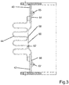
- FIG.3 A portion of a bellow compensator according to a first embodiment of the present invention is shown in Fig.3 .
- a bellow compensator comprises an inlet end pipe 40 and an opposite outlet end pipe 42 and a bellow section 44 arranged therebetween.
- the end pipes 40 respectively 42 are located at the end of one of the material hoppers respectively at the end of the valve casing and it is to be noted that the support of the end pipes 40 and 42 relative to the furnace is guaranteed by an overall support structure (not represented).
- the bellow section 44 is formed by a series of folds allowing relative movement between the inlet and outlet end pipes 40, 42.
- a non-structural flexible liner 60 is arranged on an inner wall 62 of the bellow compensator 26 and extends over at least some of the length of said bellow section 44.
- the non-structural flexible liner 60 has a first end 64 fixedly connected to the inlet end pipe 40 by means of bolts 65 and a second end 66 fixedly connected to the outlet end pipe 42 by means of bolts 67.
- the non-structural flexible liner 60 construction is adapted to let the hopper, to which it is connected, freely move relative to the valve casing, i.e. it shall absorb ideally no energy from this relative movement in order to avoid unnecessary mechanical constrains and consequently avoid wear and potentially cracks or breakage.
- the non-structural flexible liner 60 is dustproof in order to avoid dust passing therethrough and reaching the pockets of the bellow section and is thus itself either made from a dustproof material or comprises a dustproof coating.
- the non-structural flexible liner 60 is a wire mesh gasket which may comprise three layers of silicone and three layers of a para-aramid synthetic fiber such as Kevlar®. Such a non-structural flexible liner 60 has a thickness of about 5 mm and provides a gastight and dust-tight solution to prevent gas and dust from entering the inner pockets of the bellow section 44. Such a non-structural flexible liner 60 tolerates pressures up to 3 barg and temperatures of up to 200°C - momentarily even up to 400°C. With up to 20 pressure relieves per hour, each being associated with a pressure difference of up to 3 bar, such a flexible liner 60 can have a lifetime of about 5 years.
- the non-structural flexible liner 60 is arranged so as to rest on the inner-facing folds 68, or convolutions, of the bellow section 44. As pressure increases in the bellow compensator, the non-structural flexible liner 60 is pushed against the inner-facing folds 68, the latter limiting the movement of the flexible liner 60.
- a supporting plate 70 is arranged between the non-structural flexible liner 60 and the inner-facing folds 68 of the bellow section 44. Such a supporting plate 70 may extend over some or all of the height of the bellow section 44.
- both the inlet and outlet end pipes 40, 42 comprise an extension 72, 72' extending the length of the inlet and outlet end pipes 40, 42, thereby reducing the gap between the inlet and outlet end pipes 40, 42.
Landscapes
- Engineering & Computer Science (AREA)
- General Engineering & Computer Science (AREA)
- Mechanical Engineering (AREA)
- Chemical & Material Sciences (AREA)
- Metallurgy (AREA)
- Materials Engineering (AREA)
- Manufacturing & Machinery (AREA)
- Organic Chemistry (AREA)
- Vertical, Hearth, Or Arc Furnaces (AREA)
- Furnace Charging Or Discharging (AREA)
- Joints Allowing Movement (AREA)
- Waste-Gas Treatment And Other Accessory Devices For Furnaces (AREA)
- Diaphragms And Bellows (AREA)
- Filling Or Emptying Of Bunkers, Hoppers, And Tanks (AREA)
Claims (10)
- Compensateur à soufflet (18) pour une installation de chargement d'un four métallurgique, ledit compensateur à soufflet (18) comprenant un tuyau d'admission (40) et un tuyau d'évacuation opposé (42) ainsi qu'une section de soufflet (44) agencée entre ledit tuyau d'admission (40) et ledit tuyau d'évacuation (42), ladite section de soufflet (44) étant formée par une série de plis et permettant un mouvement relatif entre ledit tuyau d'admission (40) et ledit tuyau d'évacuation (42),
ledit compensateur à soufflet (18) comprenant une gaine flexible (60) agencée sur une paroi intérieure (62) dudit compensateur à soufflet (18) et s'étendant sur au moins une partie de la longueur de ladite section de soufflet (44), la gaine flexible non structurelle (60) ayant une première extrémité (64) et une seconde extrémité (66), ladite première extrémité (64) étant reliée de manière fixe audit tuyau d'admission (40) et ladite seconde extrémité (66) étant reliée de manière fixe audit tuyau d'évacuation (42) ;
caractérisé en ce que
ladite gaine flexible (60) est une gaine flexible non structurelle (60) formée par un joint d'étanchéité à treillis métallique comprenant au moins une couche réalisée à partir de silicone et au moins une couche réalisée à partir de fibre synthétique. - Compensateur à soufflet (18) selon la revendication 1, dans lequel ladite gaine flexible non structurelle (60) comprend au moins trois couches réalisées à partir de silicone et au moins trois couches réalisées à partir de fibre synthétique.
- Compensateur à soufflet (18) selon la revendication 1 ou 2, dans lequel ladite fibre synthétique est une fibre synthétique de para-amide.
- Compensateur à soufflet (18) selon l'une quelconque des revendications 1 à 3, dans lequel ladite gaine flexible non structurelle (60) est réalisée à partir d'un matériau anti-poussière ou comprend un revêtement anti-poussière.
- Compensateur à soufflet (18) selon l'une quelconque des revendications 1 à 4, dans lequel ladite gaine flexible non structurelle (60) est formée par un matériau flexible, renforcé ou non.
- Compensateur à soufflet (18) selon l'une quelconque des revendications 1 à 5, dans lequel ladite première extrémité (64) de ladite gaine flexible non structurelle (60) est reliée de manière fixe audit tuyau d'admission (40) et ladite seconde extrémité (66) de ladite gaine flexible non structurelle (60) est reliée de manière fixe audit tuyau d'évacuation (42).
- Compensateur à soufflet (18) selon la revendication 6, dans lequel ladite gaine flexible non structurelle (60) est reliée de manière fixe au tuyau d'admission et/ou d'évacuation (40, 42) au moyen d'un soudage, de boulons (65), d'attaches ou d'un adhésif.
- Compensateur à soufflet (18) selon l'une quelconque des revendications 1 à 7, dans lequel ladite gaine flexible non structurelle (60) est supportée par des plis (68) de ladite section de soufflet (44) qui sont tournés vers l'intérieur.
- Compensateur à soufflet (18) selon l'une quelconque des revendications 1 à 7, dans lequel ladite gaine flexible non structurelle (60) est supportée par une plaque support (70) agencée entre ladite gaine flexible non structurelle (60) et lesdits plis de ladite section de soufflet (44).
- Compensateur à soufflet (18) selon l'une quelconque des revendications 1 à 9, dans lequel au moins un dudit tuyau d'admission (40) et dudit tuyau d'évacuation (42) comprend une extension (72, 72') s'étendant dans la direction du tuyau opposé.
Applications Claiming Priority (2)
| Application Number | Priority Date | Filing Date | Title |
|---|---|---|---|
| LU92766A LU92766B1 (en) | 2015-07-09 | 2015-07-09 | Bellow compensator |
| PCT/EP2016/066027 WO2017005811A1 (fr) | 2015-07-09 | 2016-07-06 | Compensateur à soufflet |
Publications (2)
| Publication Number | Publication Date |
|---|---|
| EP3320249A1 EP3320249A1 (fr) | 2018-05-16 |
| EP3320249B1 true EP3320249B1 (fr) | 2019-09-18 |
Family
ID=53794458
Family Applications (1)
| Application Number | Title | Priority Date | Filing Date |
|---|---|---|---|
| EP16736137.7A Active EP3320249B1 (fr) | 2015-07-09 | 2016-07-06 | Compensateur à soufflet |
Country Status (11)
| Country | Link |
|---|---|
| US (1) | US10378071B2 (fr) |
| EP (1) | EP3320249B1 (fr) |
| JP (1) | JP6464312B2 (fr) |
| KR (1) | KR101907196B1 (fr) |
| CN (1) | CN107850247B (fr) |
| BR (1) | BR112018000228B1 (fr) |
| LU (1) | LU92766B1 (fr) |
| RU (1) | RU2695849C1 (fr) |
| TW (1) | TWI690598B (fr) |
| UA (1) | UA121988C2 (fr) |
| WO (1) | WO2017005811A1 (fr) |
Families Citing this family (6)
| Publication number | Priority date | Publication date | Assignee | Title |
|---|---|---|---|---|
| LU92766B1 (en) * | 2015-07-09 | 2017-01-30 | Wurth Paul Sa | Bellow compensator |
| US10302231B2 (en) * | 2015-07-13 | 2019-05-28 | Exotic Metals Forming Company LLC | Flexible joint assembly for high or low temperature fluid systems |
| CN110527767A (zh) * | 2019-08-14 | 2019-12-03 | 宝钢湛江钢铁有限公司 | 一种用于高炉炉顶料罐的防尘结构 |
| CN112344122A (zh) * | 2020-10-22 | 2021-02-09 | 中国一冶集团有限公司 | 一种补偿不均匀沉降的钢管管道连接结构及施工方法 |
| CN112555553A (zh) * | 2020-10-29 | 2021-03-26 | 无锡华利达金属制品有限公司 | 一种外套式弹性固定的波纹管补偿器 |
| KR102478101B1 (ko) * | 2021-12-06 | 2022-12-14 | 이진숙 | 촉매 분배 장치 |
Family Cites Families (22)
| Publication number | Priority date | Publication date | Assignee | Title |
|---|---|---|---|---|
| FR1391832A (fr) * | 1964-01-11 | 1965-03-12 | Manuf Metallurg De La Jonchere | Raccord souple pour tuyauteries |
| AT346875B (de) * | 1974-09-06 | 1978-09-15 | Wurth Anciens Ets Paul | Kompensatorverbindung zwischen zwei mit feuerfestfutter versehenen rohrstuecken und gelenkduesenstoecke mit diesen verbindungen |
| LU70943A1 (fr) | 1974-09-18 | 1975-03-06 | ||
| US4045056A (en) | 1975-10-14 | 1977-08-30 | Gennady Petrovich Kandakov | Expansion compensator for pipelines |
| AU541081B2 (en) | 1979-10-30 | 1984-12-13 | Raybestos-Manhattan, Inc. | Expansion joint |
| US4442585A (en) * | 1982-03-31 | 1984-04-17 | Mcgehee Sr Fred N | Method of construction for thermal and acoustic insulation blankets |
| JPS62145120A (ja) * | 1985-12-19 | 1987-06-29 | Ishikawajima Harima Heavy Ind Co Ltd | 高炉における原料装入量の計測方法および装置 |
| RU2026354C1 (ru) * | 1990-09-25 | 1995-01-09 | Абрамин Герман Васильевич | Распределитель шихты загрузочного устройства доменной печи |
| US5178648A (en) | 1991-07-10 | 1993-01-12 | Emtrol Corporation | Particulate filtration apparatus and method |
| JPH09268913A (ja) * | 1996-04-03 | 1997-10-14 | Honda Motor Co Ltd | エンジン排気系のフレキシブルチューブ |
| DE29617552U1 (de) * | 1996-10-09 | 1998-02-12 | Witzenmann GmbH Metallschlauch-Fabrik Pforzheim, 75175 Pforzheim | Leitungselement in Form eines Wellschlauches oder Balges |
| EP0848143B1 (fr) | 1996-12-13 | 2003-05-02 | FLEXIDER S.r.l. | Joint de découplage flexible, en particulier pour tuyau d'échappement de véhicule |
| KR200243765Y1 (ko) | 1999-05-24 | 2001-09-25 | 김용호 | 자동차 배기관용 디커플러 |
| KR20020077940A (ko) * | 2000-02-29 | 2002-10-18 | 아사히 비어 엔지니어링 리미티드 | 신축계수장치 |
| KR100353123B1 (ko) * | 2000-08-28 | 2002-09-16 | 주식회사 에스제이엠 | 자동차 배기관용 연결구 |
| EP1811045A1 (fr) * | 2006-01-20 | 2007-07-25 | Paul Wurth S.A. | Trémies multiples pour chargement d'un haut fourneau |
| DE102007004766A1 (de) * | 2007-01-31 | 2008-08-07 | Bayerische Motoren Werke Aktiengesellschaft | Wellschlauch |
| JP5096822B2 (ja) * | 2007-07-23 | 2012-12-12 | 新日鉄エンジニアリング株式会社 | 廃棄物溶融炉の熱膨張吸収構造 |
| US9261216B2 (en) | 2009-09-29 | 2016-02-16 | Tru-Flex, Llc | Exhaust system conduit with thermal/noise insulation |
| CN204114440U (zh) * | 2014-09-30 | 2015-01-21 | 姜堰市奕岑机械配件厂 | 一种新型封尘外压式膨胀节 |
| CN204300599U (zh) * | 2014-12-02 | 2015-04-29 | 江苏恒丰波纹管有限公司 | 设有柔性防尘结构的防磨膨胀节 |
| LU92766B1 (en) * | 2015-07-09 | 2017-01-30 | Wurth Paul Sa | Bellow compensator |
-
2015
- 2015-07-09 LU LU92766A patent/LU92766B1/en active IP Right Grant
-
2016
- 2016-07-06 UA UAA201800245A patent/UA121988C2/uk unknown
- 2016-07-06 JP JP2018500483A patent/JP6464312B2/ja active Active
- 2016-07-06 RU RU2018103034A patent/RU2695849C1/ru active
- 2016-07-06 EP EP16736137.7A patent/EP3320249B1/fr active Active
- 2016-07-06 CN CN201680040188.XA patent/CN107850247B/zh active Active
- 2016-07-06 KR KR1020187002105A patent/KR101907196B1/ko active Active
- 2016-07-06 BR BR112018000228-3A patent/BR112018000228B1/pt active IP Right Grant
- 2016-07-06 US US15/741,964 patent/US10378071B2/en active Active
- 2016-07-06 WO PCT/EP2016/066027 patent/WO2017005811A1/fr not_active Ceased
- 2016-07-11 TW TW105121749A patent/TWI690598B/zh active
Non-Patent Citations (1)
| Title |
|---|
| None * |
Also Published As
| Publication number | Publication date |
|---|---|
| CN107850247B (zh) | 2019-06-28 |
| TWI690598B (zh) | 2020-04-11 |
| UA121988C2 (uk) | 2020-08-25 |
| WO2017005811A1 (fr) | 2017-01-12 |
| BR112018000228A2 (pt) | 2018-09-04 |
| CN107850247A (zh) | 2018-03-27 |
| US20180195139A1 (en) | 2018-07-12 |
| BR112018000228B1 (pt) | 2022-11-01 |
| LU92766B1 (en) | 2017-01-30 |
| US10378071B2 (en) | 2019-08-13 |
| KR20180012340A (ko) | 2018-02-05 |
| KR101907196B1 (ko) | 2018-10-11 |
| RU2695849C1 (ru) | 2019-07-29 |
| TW201710510A (zh) | 2017-03-16 |
| JP6464312B2 (ja) | 2019-02-06 |
| EP3320249A1 (fr) | 2018-05-16 |
| JP2018527540A (ja) | 2018-09-20 |
Similar Documents
| Publication | Publication Date | Title |
|---|---|---|
| EP3320249B1 (fr) | Compensateur à soufflet | |
| EP2529037B1 (fr) | Dispositif de chargement pour réacteur métallurgique | |
| US8808616B2 (en) | Bustle pipe arrangement | |
| US9028743B2 (en) | Bustle pipe arrangement | |
| CN105570879B (zh) | 带有一级自平衡返料器的多流程循环流化床锅炉 | |
| US8833801B2 (en) | Compensator for connecting pipes for dust-laden flue gas | |
| CN217376586U (zh) | 一种带密封结构的金属橡胶复合补偿防尘装置 | |
| US9518688B2 (en) | Expansion joint in a vertical channel | |
| CN107575688A (zh) | 一种膨胀节 | |
| CN210123062U (zh) | 一种电厂锅炉下联箱与渣井连接用非金属膨胀节 | |
| CN208107416U (zh) | 一种耐高温防磨型组合补偿器 | |
| CN114538144A (zh) | 一种带密封结构的金属橡胶复合补偿防尘装置 | |
| US20170343145A1 (en) | High-Pressure Self-Cleaning Elbow |
Legal Events
| Date | Code | Title | Description |
|---|---|---|---|
| STAA | Information on the status of an ep patent application or granted ep patent |
Free format text: STATUS: THE INTERNATIONAL PUBLICATION HAS BEEN MADE |
|
| PUAI | Public reference made under article 153(3) epc to a published international application that has entered the european phase |
Free format text: ORIGINAL CODE: 0009012 |
|
| STAA | Information on the status of an ep patent application or granted ep patent |
Free format text: STATUS: REQUEST FOR EXAMINATION WAS MADE |
|
| 17P | Request for examination filed |
Effective date: 20180124 |
|
| AK | Designated contracting states |
Kind code of ref document: A1 Designated state(s): AL AT BE BG CH CY CZ DE DK EE ES FI FR GB GR HR HU IE IS IT LI LT LU LV MC MK MT NL NO PL PT RO RS SE SI SK SM TR |
|
| AX | Request for extension of the european patent |
Extension state: BA ME |
|
| STAA | Information on the status of an ep patent application or granted ep patent |
Free format text: STATUS: EXAMINATION IS IN PROGRESS |
|
| 17Q | First examination report despatched |
Effective date: 20180516 |
|
| DAV | Request for validation of the european patent (deleted) | ||
| DAX | Request for extension of the european patent (deleted) | ||
| GRAP | Despatch of communication of intention to grant a patent |
Free format text: ORIGINAL CODE: EPIDOSNIGR1 |
|
| STAA | Information on the status of an ep patent application or granted ep patent |
Free format text: STATUS: GRANT OF PATENT IS INTENDED |
|
| INTG | Intention to grant announced |
Effective date: 20190424 |
|
| GRAS | Grant fee paid |
Free format text: ORIGINAL CODE: EPIDOSNIGR3 |
|
| GRAA | (expected) grant |
Free format text: ORIGINAL CODE: 0009210 |
|
| STAA | Information on the status of an ep patent application or granted ep patent |
Free format text: STATUS: THE PATENT HAS BEEN GRANTED |
|
| AK | Designated contracting states |
Kind code of ref document: B1 Designated state(s): AL AT BE BG CH CY CZ DE DK EE ES FI FR GB GR HR HU IE IS IT LI LT LU LV MC MK MT NL NO PL PT RO RS SE SI SK SM TR |
|
| REG | Reference to a national code |
Ref country code: GB Ref legal event code: FG4D |
|
| REG | Reference to a national code |
Ref country code: CH Ref legal event code: EP |
|
| REG | Reference to a national code |
Ref country code: DE Ref legal event code: R096 Ref document number: 602016020860 Country of ref document: DE |
|
| REG | Reference to a national code |
Ref country code: AT Ref legal event code: REF Ref document number: 1181738 Country of ref document: AT Kind code of ref document: T Effective date: 20191015 |
|
| REG | Reference to a national code |
Ref country code: IE Ref legal event code: FG4D |
|
| REG | Reference to a national code |
Ref country code: DE Ref legal event code: R082 Ref document number: 602016020860 Country of ref document: DE Representative=s name: OFFICE FREYLINGER S.A., LU |
|
| REG | Reference to a national code |
Ref country code: NL Ref legal event code: FP |
|
| PG25 | Lapsed in a contracting state [announced via postgrant information from national office to epo] |
Ref country code: FI Free format text: LAPSE BECAUSE OF FAILURE TO SUBMIT A TRANSLATION OF THE DESCRIPTION OR TO PAY THE FEE WITHIN THE PRESCRIBED TIME-LIMIT Effective date: 20190918 Ref country code: LT Free format text: LAPSE BECAUSE OF FAILURE TO SUBMIT A TRANSLATION OF THE DESCRIPTION OR TO PAY THE FEE WITHIN THE PRESCRIBED TIME-LIMIT Effective date: 20190918 Ref country code: HR Free format text: LAPSE BECAUSE OF FAILURE TO SUBMIT A TRANSLATION OF THE DESCRIPTION OR TO PAY THE FEE WITHIN THE PRESCRIBED TIME-LIMIT Effective date: 20190918 Ref country code: BG Free format text: LAPSE BECAUSE OF FAILURE TO SUBMIT A TRANSLATION OF THE DESCRIPTION OR TO PAY THE FEE WITHIN THE PRESCRIBED TIME-LIMIT Effective date: 20191218 Ref country code: SE Free format text: LAPSE BECAUSE OF FAILURE TO SUBMIT A TRANSLATION OF THE DESCRIPTION OR TO PAY THE FEE WITHIN THE PRESCRIBED TIME-LIMIT Effective date: 20190918 Ref country code: NO Free format text: LAPSE BECAUSE OF FAILURE TO SUBMIT A TRANSLATION OF THE DESCRIPTION OR TO PAY THE FEE WITHIN THE PRESCRIBED TIME-LIMIT Effective date: 20191218 |
|
| REG | Reference to a national code |
Ref country code: LT Ref legal event code: MG4D |
|
| PG25 | Lapsed in a contracting state [announced via postgrant information from national office to epo] |
Ref country code: AL Free format text: LAPSE BECAUSE OF FAILURE TO SUBMIT A TRANSLATION OF THE DESCRIPTION OR TO PAY THE FEE WITHIN THE PRESCRIBED TIME-LIMIT Effective date: 20190918 Ref country code: LV Free format text: LAPSE BECAUSE OF FAILURE TO SUBMIT A TRANSLATION OF THE DESCRIPTION OR TO PAY THE FEE WITHIN THE PRESCRIBED TIME-LIMIT Effective date: 20190918 Ref country code: GR Free format text: LAPSE BECAUSE OF FAILURE TO SUBMIT A TRANSLATION OF THE DESCRIPTION OR TO PAY THE FEE WITHIN THE PRESCRIBED TIME-LIMIT Effective date: 20191219 Ref country code: RS Free format text: LAPSE BECAUSE OF FAILURE TO SUBMIT A TRANSLATION OF THE DESCRIPTION OR TO PAY THE FEE WITHIN THE PRESCRIBED TIME-LIMIT Effective date: 20190918 |
|
| PG25 | Lapsed in a contracting state [announced via postgrant information from national office to epo] |
Ref country code: PL Free format text: LAPSE BECAUSE OF FAILURE TO SUBMIT A TRANSLATION OF THE DESCRIPTION OR TO PAY THE FEE WITHIN THE PRESCRIBED TIME-LIMIT Effective date: 20190918 Ref country code: PT Free format text: LAPSE BECAUSE OF FAILURE TO SUBMIT A TRANSLATION OF THE DESCRIPTION OR TO PAY THE FEE WITHIN THE PRESCRIBED TIME-LIMIT Effective date: 20200120 Ref country code: EE Free format text: LAPSE BECAUSE OF FAILURE TO SUBMIT A TRANSLATION OF THE DESCRIPTION OR TO PAY THE FEE WITHIN THE PRESCRIBED TIME-LIMIT Effective date: 20190918 Ref country code: ES Free format text: LAPSE BECAUSE OF FAILURE TO SUBMIT A TRANSLATION OF THE DESCRIPTION OR TO PAY THE FEE WITHIN THE PRESCRIBED TIME-LIMIT Effective date: 20190918 Ref country code: RO Free format text: LAPSE BECAUSE OF FAILURE TO SUBMIT A TRANSLATION OF THE DESCRIPTION OR TO PAY THE FEE WITHIN THE PRESCRIBED TIME-LIMIT Effective date: 20190918 |
|
| PG25 | Lapsed in a contracting state [announced via postgrant information from national office to epo] |
Ref country code: SM Free format text: LAPSE BECAUSE OF FAILURE TO SUBMIT A TRANSLATION OF THE DESCRIPTION OR TO PAY THE FEE WITHIN THE PRESCRIBED TIME-LIMIT Effective date: 20190918 Ref country code: IS Free format text: LAPSE BECAUSE OF FAILURE TO SUBMIT A TRANSLATION OF THE DESCRIPTION OR TO PAY THE FEE WITHIN THE PRESCRIBED TIME-LIMIT Effective date: 20200224 Ref country code: SK Free format text: LAPSE BECAUSE OF FAILURE TO SUBMIT A TRANSLATION OF THE DESCRIPTION OR TO PAY THE FEE WITHIN THE PRESCRIBED TIME-LIMIT Effective date: 20190918 Ref country code: CZ Free format text: LAPSE BECAUSE OF FAILURE TO SUBMIT A TRANSLATION OF THE DESCRIPTION OR TO PAY THE FEE WITHIN THE PRESCRIBED TIME-LIMIT Effective date: 20190918 |
|
| REG | Reference to a national code |
Ref country code: DE Ref legal event code: R097 Ref document number: 602016020860 Country of ref document: DE |
|
| PLBE | No opposition filed within time limit |
Free format text: ORIGINAL CODE: 0009261 |
|
| STAA | Information on the status of an ep patent application or granted ep patent |
Free format text: STATUS: NO OPPOSITION FILED WITHIN TIME LIMIT |
|
| PG2D | Information on lapse in contracting state deleted |
Ref country code: IS |
|
| PG25 | Lapsed in a contracting state [announced via postgrant information from national office to epo] |
Ref country code: DK Free format text: LAPSE BECAUSE OF FAILURE TO SUBMIT A TRANSLATION OF THE DESCRIPTION OR TO PAY THE FEE WITHIN THE PRESCRIBED TIME-LIMIT Effective date: 20190918 Ref country code: IS Free format text: LAPSE BECAUSE OF FAILURE TO SUBMIT A TRANSLATION OF THE DESCRIPTION OR TO PAY THE FEE WITHIN THE PRESCRIBED TIME-LIMIT Effective date: 20200119 |
|
| 26N | No opposition filed |
Effective date: 20200619 |
|
| PG25 | Lapsed in a contracting state [announced via postgrant information from national office to epo] |
Ref country code: SI Free format text: LAPSE BECAUSE OF FAILURE TO SUBMIT A TRANSLATION OF THE DESCRIPTION OR TO PAY THE FEE WITHIN THE PRESCRIBED TIME-LIMIT Effective date: 20190918 |
|
| PG25 | Lapsed in a contracting state [announced via postgrant information from national office to epo] |
Ref country code: MC Free format text: LAPSE BECAUSE OF FAILURE TO SUBMIT A TRANSLATION OF THE DESCRIPTION OR TO PAY THE FEE WITHIN THE PRESCRIBED TIME-LIMIT Effective date: 20190918 |
|
| REG | Reference to a national code |
Ref country code: CH Ref legal event code: PL |
|
| PG25 | Lapsed in a contracting state [announced via postgrant information from national office to epo] |
Ref country code: IE Free format text: LAPSE BECAUSE OF NON-PAYMENT OF DUE FEES Effective date: 20200706 Ref country code: LU Free format text: LAPSE BECAUSE OF NON-PAYMENT OF DUE FEES Effective date: 20200706 Ref country code: LI Free format text: LAPSE BECAUSE OF NON-PAYMENT OF DUE FEES Effective date: 20200731 Ref country code: CH Free format text: LAPSE BECAUSE OF NON-PAYMENT OF DUE FEES Effective date: 20200731 |
|
| REG | Reference to a national code |
Ref country code: AT Ref legal event code: UEP Ref document number: 1181738 Country of ref document: AT Kind code of ref document: T Effective date: 20190918 |
|
| PG25 | Lapsed in a contracting state [announced via postgrant information from national office to epo] |
Ref country code: TR Free format text: LAPSE BECAUSE OF FAILURE TO SUBMIT A TRANSLATION OF THE DESCRIPTION OR TO PAY THE FEE WITHIN THE PRESCRIBED TIME-LIMIT Effective date: 20190918 Ref country code: MT Free format text: LAPSE BECAUSE OF FAILURE TO SUBMIT A TRANSLATION OF THE DESCRIPTION OR TO PAY THE FEE WITHIN THE PRESCRIBED TIME-LIMIT Effective date: 20190918 Ref country code: CY Free format text: LAPSE BECAUSE OF FAILURE TO SUBMIT A TRANSLATION OF THE DESCRIPTION OR TO PAY THE FEE WITHIN THE PRESCRIBED TIME-LIMIT Effective date: 20190918 |
|
| PG25 | Lapsed in a contracting state [announced via postgrant information from national office to epo] |
Ref country code: MK Free format text: LAPSE BECAUSE OF FAILURE TO SUBMIT A TRANSLATION OF THE DESCRIPTION OR TO PAY THE FEE WITHIN THE PRESCRIBED TIME-LIMIT Effective date: 20190918 |
|
| P01 | Opt-out of the competence of the unified patent court (upc) registered |
Free format text: CASE NUMBER: UPC_APP_414697/2023 Effective date: 20230524 |
|
| PGFP | Annual fee paid to national office [announced via postgrant information from national office to epo] |
Ref country code: GB Payment date: 20250617 Year of fee payment: 10 |
|
| PGFP | Annual fee paid to national office [announced via postgrant information from national office to epo] |
Ref country code: NL Payment date: 20250617 Year of fee payment: 10 Ref country code: BE Payment date: 20250617 Year of fee payment: 10 |
|
| PGFP | Annual fee paid to national office [announced via postgrant information from national office to epo] |
Ref country code: FR Payment date: 20250617 Year of fee payment: 10 |
|
| PGFP | Annual fee paid to national office [announced via postgrant information from national office to epo] |
Ref country code: DE Payment date: 20250616 Year of fee payment: 10 |
|
| PGFP | Annual fee paid to national office [announced via postgrant information from national office to epo] |
Ref country code: IT Payment date: 20250701 Year of fee payment: 10 |
|
| PGFP | Annual fee paid to national office [announced via postgrant information from national office to epo] |
Ref country code: AT Payment date: 20250617 Year of fee payment: 10 |