EP3319501B1 - Lave-vaisselle pourvu d'un système de séchage - Google Patents
Lave-vaisselle pourvu d'un système de séchage Download PDFInfo
- Publication number
- EP3319501B1 EP3319501B1 EP16719881.1A EP16719881A EP3319501B1 EP 3319501 B1 EP3319501 B1 EP 3319501B1 EP 16719881 A EP16719881 A EP 16719881A EP 3319501 B1 EP3319501 B1 EP 3319501B1
- Authority
- EP
- European Patent Office
- Prior art keywords
- dishwasher
- water
- coolant
- items
- pipe system
- Prior art date
- Legal status (The legal status is an assumption and is not a legal conclusion. Google has not performed a legal analysis and makes no representation as to the accuracy of the status listed.)
- Active
Links
- 238000001035 drying Methods 0.000 title claims description 53
- 238000003795 desorption Methods 0.000 claims description 75
- 239000007921 spray Substances 0.000 claims description 61
- 238000005406 washing Methods 0.000 claims description 61
- XLYOFNOQVPJJNP-UHFFFAOYSA-N water Substances O XLYOFNOQVPJJNP-UHFFFAOYSA-N 0.000 claims description 59
- 238000001179 sorption measurement Methods 0.000 claims description 49
- 239000002826 coolant Substances 0.000 claims description 45
- 239000007788 liquid Substances 0.000 claims description 44
- 238000005507 spraying Methods 0.000 claims description 12
- 238000004140 cleaning Methods 0.000 claims description 9
- 230000008569 process Effects 0.000 claims description 5
- 229910021536 Zeolite Inorganic materials 0.000 claims description 4
- HNPSIPDUKPIQMN-UHFFFAOYSA-N dioxosilane;oxo(oxoalumanyloxy)alumane Chemical compound O=[Si]=O.O=[Al]O[Al]=O HNPSIPDUKPIQMN-UHFFFAOYSA-N 0.000 claims description 4
- 239000010457 zeolite Substances 0.000 claims description 4
- 239000011521 glass Substances 0.000 claims description 3
- 238000000034 method Methods 0.000 claims description 3
- 238000010521 absorption reaction Methods 0.000 claims 1
- 230000009977 dual effect Effects 0.000 claims 1
- 238000001816 cooling Methods 0.000 description 25
- 239000000463 material Substances 0.000 description 16
- 230000001954 sterilising effect Effects 0.000 description 8
- 238000011068 loading method Methods 0.000 description 7
- 238000004659 sterilization and disinfection Methods 0.000 description 7
- 238000010438 heat treatment Methods 0.000 description 6
- 230000008901 benefit Effects 0.000 description 5
- 238000011161 development Methods 0.000 description 5
- 230000018109 developmental process Effects 0.000 description 5
- 239000002250 absorbent Substances 0.000 description 4
- 238000005086 pumping Methods 0.000 description 4
- 239000006096 absorbing agent Substances 0.000 description 3
- 239000003795 chemical substances by application Substances 0.000 description 3
- 230000008878 coupling Effects 0.000 description 3
- 238000010168 coupling process Methods 0.000 description 3
- 238000005859 coupling reaction Methods 0.000 description 3
- 239000003599 detergent Substances 0.000 description 3
- 238000011010 flushing procedure Methods 0.000 description 3
- 238000010186 staining Methods 0.000 description 3
- CBENFWSGALASAD-UHFFFAOYSA-N Ozone Chemical compound [O-][O+]=O CBENFWSGALASAD-UHFFFAOYSA-N 0.000 description 2
- 239000000110 cooling liquid Substances 0.000 description 2
- 238000013461 design Methods 0.000 description 2
- 238000010586 diagram Methods 0.000 description 2
- 239000013505 freshwater Substances 0.000 description 2
- 230000009467 reduction Effects 0.000 description 2
- 238000006424 Flood reaction Methods 0.000 description 1
- 230000004308 accommodation Effects 0.000 description 1
- 230000009471 action Effects 0.000 description 1
- 230000006978 adaptation Effects 0.000 description 1
- 239000003463 adsorbent Substances 0.000 description 1
- 238000007605 air drying Methods 0.000 description 1
- 230000008859 change Effects 0.000 description 1
- 239000012459 cleaning agent Substances 0.000 description 1
- 238000009833 condensation Methods 0.000 description 1
- 230000005494 condensation Effects 0.000 description 1
- 238000010411 cooking Methods 0.000 description 1
- 230000001419 dependent effect Effects 0.000 description 1
- 239000002274 desiccant Substances 0.000 description 1
- 238000004851 dishwashing Methods 0.000 description 1
- 239000012530 fluid Substances 0.000 description 1
- -1 for example Substances 0.000 description 1
- 230000017525 heat dissipation Effects 0.000 description 1
- 230000006872 improvement Effects 0.000 description 1
- 230000010354 integration Effects 0.000 description 1
- 230000003287 optical effect Effects 0.000 description 1
- 239000004033 plastic Substances 0.000 description 1
- 238000012545 processing Methods 0.000 description 1
- 238000010926 purge Methods 0.000 description 1
- 230000001105 regulatory effect Effects 0.000 description 1
- 238000009420 retrofitting Methods 0.000 description 1
- 239000002594 sorbent Substances 0.000 description 1
- 229910001220 stainless steel Inorganic materials 0.000 description 1
- 239000010935 stainless steel Substances 0.000 description 1
- 238000012549 training Methods 0.000 description 1
Images


Classifications
-
- A—HUMAN NECESSITIES
- A47—FURNITURE; DOMESTIC ARTICLES OR APPLIANCES; COFFEE MILLS; SPICE MILLS; SUCTION CLEANERS IN GENERAL
- A47L—DOMESTIC WASHING OR CLEANING; SUCTION CLEANERS IN GENERAL
- A47L15/00—Washing or rinsing machines for crockery or tableware
- A47L15/42—Details
- A47L15/48—Drying arrangements
- A47L15/481—Drying arrangements by using water absorbent materials, e.g. Zeolith
-
- A—HUMAN NECESSITIES
- A47—FURNITURE; DOMESTIC ARTICLES OR APPLIANCES; COFFEE MILLS; SPICE MILLS; SUCTION CLEANERS IN GENERAL
- A47L—DOMESTIC WASHING OR CLEANING; SUCTION CLEANERS IN GENERAL
- A47L15/00—Washing or rinsing machines for crockery or tableware
- A47L15/0018—Controlling processes, i.e. processes to control the operation of the machine characterised by the purpose or target of the control
- A47L15/0021—Regulation of operational steps within the washing processes, e.g. optimisation or improvement of operational steps depending from the detergent nature or from the condition of the crockery
- A47L15/0042—Desorption phases of reversibly dehydrogenated drying material, e.g. zeolite in a sorption drying system
-
- A—HUMAN NECESSITIES
- A47—FURNITURE; DOMESTIC ARTICLES OR APPLIANCES; COFFEE MILLS; SPICE MILLS; SUCTION CLEANERS IN GENERAL
- A47L—DOMESTIC WASHING OR CLEANING; SUCTION CLEANERS IN GENERAL
- A47L15/00—Washing or rinsing machines for crockery or tableware
- A47L15/0018—Controlling processes, i.e. processes to control the operation of the machine characterised by the purpose or target of the control
- A47L15/0052—Noise reduction
-
- A—HUMAN NECESSITIES
- A47—FURNITURE; DOMESTIC ARTICLES OR APPLIANCES; COFFEE MILLS; SPICE MILLS; SUCTION CLEANERS IN GENERAL
- A47L—DOMESTIC WASHING OR CLEANING; SUCTION CLEANERS IN GENERAL
- A47L15/00—Washing or rinsing machines for crockery or tableware
- A47L15/42—Details
- A47L15/4214—Water supply, recirculation or discharge arrangements; Devices therefor
- A47L15/4219—Water recirculation
-
- A—HUMAN NECESSITIES
- A47—FURNITURE; DOMESTIC ARTICLES OR APPLIANCES; COFFEE MILLS; SPICE MILLS; SUCTION CLEANERS IN GENERAL
- A47L—DOMESTIC WASHING OR CLEANING; SUCTION CLEANERS IN GENERAL
- A47L15/00—Washing or rinsing machines for crockery or tableware
- A47L15/42—Details
- A47L15/4236—Arrangements to sterilize or disinfect dishes or washing liquids
- A47L15/424—Arrangements to sterilize or disinfect dishes or washing liquids by using ozone
-
- A—HUMAN NECESSITIES
- A47—FURNITURE; DOMESTIC ARTICLES OR APPLIANCES; COFFEE MILLS; SPICE MILLS; SUCTION CLEANERS IN GENERAL
- A47L—DOMESTIC WASHING OR CLEANING; SUCTION CLEANERS IN GENERAL
- A47L15/00—Washing or rinsing machines for crockery or tableware
- A47L15/42—Details
- A47L15/4236—Arrangements to sterilize or disinfect dishes or washing liquids
- A47L15/4242—Arrangements to sterilize or disinfect dishes or washing liquids by using ultraviolet generators
-
- A—HUMAN NECESSITIES
- A47—FURNITURE; DOMESTIC ARTICLES OR APPLIANCES; COFFEE MILLS; SPICE MILLS; SUCTION CLEANERS IN GENERAL
- A47L—DOMESTIC WASHING OR CLEANING; SUCTION CLEANERS IN GENERAL
- A47L15/00—Washing or rinsing machines for crockery or tableware
- A47L15/42—Details
- A47L15/48—Drying arrangements
- A47L15/486—Blower arrangements
Definitions
- the invention relates to a dishwasher, in particular a domestic dishwasher, with a rinsing container for cleaning dishes, glasses, cutlery or similar items to be washed and with a phase-absorbing agent of a sorption drying device, in particular based on zeolite, with heated and water-containing during at least one desorption phase of the water-absorbing agent Air can be introduced into the washing compartment via at least one blow-out opening, according to the preamble of claim 1.
- sorption drying devices with a water-absorbing agent or reversibly dehydrable sorption material, such as, for example, zeolite.
- adsorption phase water-containing air is passed out of the washing compartment through the sorption drying device.
- the sorption material absorbs water from the air flowing through and / or water adheres to the sorption material so that the items to be washed can be dried in the washing container.
- this water is released again by the sorption material while the reversibly dehydratable sorbent is heated (by means of a heater) and blown out into the rinsing container.
- Such a desorption phase can take place, for example, before the actual drying cycle of the dishwashing cycle of a dishwashing program and has the advantage that residues of detergent, in particular rinse aid, remaining on the wash ware are diluted by the water vapor which is formed, and so staining is reduced.
- very high temperatures occur at the blow-out opening, for example above 200 ° C.
- items to be washed can be damaged in the vicinity of the blow-out opening, particularly if this is made of plastic.
- a crockery basket or another accommodation unit, such as a cutlery basket which accommodates items to be washed and which is in the vicinity of the blow-out opening.
- one or more wall surfaces of the washing compartment can become so hot, if necessary, that air flows from the blow-out opening so that touching them can be uncomfortable for an operator if the operator opens the door of the dishwasher during a desorption phase and into the washing compartment with one hand such a strongly heated wall part reaches.
- there may even be a risk of burns or scalding for an operator for example if the operator opens the door, thereby interrupting the washing cycle during a desorption phase, and the person reaches into the washing container and with too much heated items, too much heated parts a crockery basket and / or an excessively heated wall surface of the washing container comes into contact. Cooling of the blow-out opening is therefore sought.
- the invention is based on the problem of achieving an improvement here.
- blow-out opening can be cooled according to claim 1 by means of a specially provided, separate, and directed towards this coolant, it is not necessary that the blow-out opening is cooled by a spray device in the washing container, in particular a rotating spray arm, which is used for spraying Washware is provided in the wash container.
- a spray device in the washing container, in particular a rotating spray arm, which is used for spraying Washware is provided in the wash container.
- the spraying of liquid onto the items to be washed by the spraying device can thus advantageously be restricted or reduced or avoided entirely.
- the pumping capacity of a pump in particular a circulating pump, which is provided for conveying washing liquid or rinsing liquor to one or more spray devices arranged in the rinsing container, can do this be at least significantly reduced during the respective desorption phase, so that the pump noise of the pump is reduced accordingly and thus the operating noise of the dishwasher as a whole is reduced.
- the pump output can preferably be reduced by reducing the speed of the pump.
- the outlet temperature of the air which flows out of the blow-out opening is reduced compared to the desorption temperature of the air which it originally had in the respective desorption phase after flowing through the sorption unit of the sorption drying device which has the reversibly dehydratable sorption material.
- Desorbing the reversibly dehydratable sorption material is expediently brought about by heating it by means of an electrical heater assigned to the sorption unit and flowing air through it or by flowing hot air which (viewed in the direction of air flow) has previously been heated by means of an electrical heater.
- the air that leaves the sorption unit during a desorption phase has, in particular, a desorption temperature between 200 ° C. and 350 ° C.
- the air leaving the blow-out opening and entering the rinsing container now has an outlet temperature, which is preferably less than or equal to 70 ° C., by cooling the blow-out opening by means of the coolant application device according to the invention.
- At least one feed pipe for coolant, in particular coolant is additionally, i.e. Provided specifically for the one or more spray devices, in particular rotating spray arms in the washing mode, which serve to apply wash liquid or wash liquor to washware.
- the device for applying coolant can also be formed by a rotatably mounted spray arm, which, however, is brought into a specific stationary cooling position, preferably a rest or standstill position, for the majority of the desorption phase in such a way that a liquid spray jet from at least one nozzle of the spray arm on the discharge opening and / or its surroundings for the predominant duration of the desorption phase is directed.
- This spray arm which remains in the specific cooling position during the desorption phase, preferably "parked” or fixed there, then likewise forms a specially provided device for the targeted application of coolant to the blow-out opening.
- the device for the application of coolant can expediently be fluidly coupled to the existing liquid circulation circuit of the dishwasher, which usually comprises a circulation pump, one or more spray devices arranged in the washing container and associated liquid connection lines, and / or possibly a water switch.
- the speed of the circulation pump is preferably set lower during the respective desorption phase than during the washing or spraying operation of the dishwasher, in which washing liquid is sprayed onto the items to be cleaned from the one or more spray devices, in particular rotating spray arms.
- This has the advantage that the pump, which rotates more slowly during the desorption phase, can lower the noise level of the dishwasher during the desorption phase compared to the noise level during washing operation, in which the one or more spray devices spray washing liquid onto the items to be washed with the required spray pressure.
- the speed of the circulation pump can in particular be set in such a way that during the respective desorption phase essentially no more rinsing liquid (as in the rinsing mode) is sprayed onto the items to be washed by the one or more spray devices, but only from the device for applying coolant only to the items Blow-out opening coolant liquid, especially clear water, is discharged.
- a rinse cycle comprises one or more partial rinse cycles, such as pre-rinsing, cleaning, intermediate rinsing, rinsing, in which washing liquid is sprayed onto the items to be cleaned in the washing container by means of one or more spray devices.
- the desorption phase can expediently take place during at least one such partial rinse cycle. In particular, it is energy-saving if the desorption phase is carried out at least partially during a partial wash cycle in which the washing-up liquid and / or washware is heated to a minimum temperature is required.
- Such a partial rinse cycle with rinsing liquid to be heated can in particular be the cleaning cycle and / or rinse cycle.
- the desorption phase can either take place completely during only one partial rinse cycle or can be divided over several partial rinse cycles.
- the desorption phase takes place at least partially immediately before the final drying cycle of a dishwasher program.
- This has the advantage that the water which is expelled from the sorption material during its desorption phase due to its heating up and is conveyed as water vapor through the blow-out opening into the washing container by the air forcibly flowing through the sorption material, also settles on the items to be washed and there any liquid residues, in particular detergent and / or rinse aid residues, are diluted, so that after the drying cycle, stains visible to the user are largely avoided.
- the wash ware is heated by the hot air flowing into the wash container from the blow-out opening during desorbing, so that what is known as self-drying of the wash ware is subsequently improved in addition to sorption drying in the drying cycle.
- the inherent heat drying is based on the difference between the temperature of the wash items and the temperature of the walls of the wash container. The greater the temperature difference and the longer the temperature difference remains during the drying cycle, the better condensation of moisture from the air in the washing compartment occurs on the walls which are cooler than the items to be washed.
- a rinse cycle of a dishwasher program can expediently be carried out.
- the desorption phase is advantageously carried out during the end section of the final rinse cycle after the spray operation has been stopped.
- the discharge opening can then be cooled with the rinse aid liquid from the rinse cycle during the desorption phase.
- the dishwasher provides a specific dishwashing program that only, i.e. exclusively comprises a rinse cycle and a subsequent drying cycle, a desorption phase being advantageously carried out during the end section of the rinse cycle after the previous spray operation has been stopped.
- the desorption phase is carried out during this end section of the rinse cycle, and the sorption phase of the sorption drying device is carried out during the drying cycle.
- the discharge opening can then be cooled with the rinse aid liquid from the rinse cycle during the desorption phase.
- the rinse aid cycle can also be omitted entirely. Then only the desorption phase precedes the drying cycle. In this case, water is expediently supplied as a coolant to the washing container.
- a specific “only drying” dishwashing program can be provided for this embodiment variant.
- a spray arm for example, can be unloaded in this phase and also not itself contribute to the development of noise.
- water can be used as the coolant, so that a high cooling capacity and a targeted area-wide application of the blow-out cap are possible.
- the water in the dishwasher can advantageously be circulated and used repeatedly as a coolant, so that the water requirement is low and continuous heat dissipation is nevertheless possible in this phase.
- the application of coolant can advantageously be operated without simultaneous introduction of new washing liquor, in particular fresh water, into the washing container in order to thereby minimize the water circulation and also the required pump power and noise.
- the coolant supply has its own pipe system, this is at least partially independent of a liquid supply system for the wash ware.
- the branch of the own pipe system provided for the coolant supply can be designed from the wash load application system in such a way that the pipe system specific for the coolant supply is only acted upon by water at a low flow rate, the water flowing past the branch at a higher flow rate.
- the branch from a riser pipe to the upper spray arm can be made. Then this only needs to be acted upon with water for cooling down to the branch, i.e. only up to a height of a few centimeters, whereas a rise of several tens of centimeters would be required to act on the upper spray arm. Accordingly, the pumping power for cooling can be significantly reduced.
- the own pipe system for cooling can run at least in areas behind a rear wall of the washing compartment.
- the application end of the pipe system for the application of coolant can be narrowed like a nozzle.
- the desorption phase of the water-absorbent agent is particularly advantageously within a rinse cycle before a drying phase of the dishes associated with adsorption of the water-absorbent agent, in order to be able to carry out the drying of the washware as the last phase.
- the processes of desorption, adsorption and other phases can be controlled via an automated process program.
- the dishwasher also has a double function for sterilizing items to be washed.
- the sterilization can preferably already be effected solely by the air flowing out of the blow-out opening during a desorption phase.
- an additional UV lamp and / or an ozone generator can also be provided for the sterilization, for example.
- a device for supplying coolant to a blow-out device having one or more blow-out openings is provided in addition to the one or more spray devices in the washing container.
- this device for the application of coolant is designed to be stationary or stationary and to direct at least one water jet onto the blow-out device continuously with the same jet direction during a partial section or the total duration of the respective desorption phase.
- the jet direction of the jet of coolant, in particular water, emerging from the coolant application device therefore preferably remains the same, i.e. the coolant jet is stationary or largely stationary.
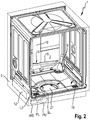
- dishwasher 1 is a household dishwasher and has as part of a body '5 a washing container 2 for receiving items to be processed such as dishes, pots, cutlery, glasses, cooking utensils and. on.
- the items to be washed can be held, for example, in crockery baskets 11 and / or in a cutlery drawer 10, and / or in another item to be washed, and can be loaded with wash liquor or wash liquor liquid by one or more spray devices, such as rotatably mounted spray arms.
- the rinsing container 2 can have an at least substantially rectangular plan with a front side V facing the user in the operating position.
- the front side V can form part of a kitchen front from kitchen furniture standing next to one another or, in the case of a standalone device, also without reference to other furniture.
- the rinsing container 2 can be closed in particular on this front side V by a door 3.
- This door 3 is in Figure 1 shown in a partially open position and then at an angle to the vertical. In its closed position, on the other hand, it stands upright and, according to the drawing, can be swiveled forward and downward in the direction of arrow 4 about its opening about a lower horizontal axis, so that it lies at least almost horizontally in the fully open position.
- the door 3 On its outer and front side V, which is vertical in the closed position and faces the user, the door 3 can be provided with a decorative plate 6 in order to experience an optical and / or haptic upgrade and / or an adaptation to surrounding kitchen furniture.
- the dishwasher 1 is designed here as a stand-alone device or as a so-called partially integrated or also as a fully integrated device.
- the body 5 can also essentially end with the outer walls of the washing compartment 2.
- a housing surrounding this outside can then be partially or completely unnecessary.
- the movable door 3 is assigned in its upper region an operating panel 8 which extends in the transverse direction Q and which can comprise an engagement opening 7 accessible from the front for manual opening and / or closing of the door 3.
- the dishwasher 1 has at least one blow-out opening 9 opening into the washing container 2, via which air can be introduced into the washing container 2 during at least one phase within a program sequence.
- Other numbers of blow-out openings 9 may also be possible.
- the dishwasher 1 is provided with a sorption drying device 12, which is shown in FIG Figure 2 dash-dotted and only schematically drawn. This contains in phases in a sorption container water-absorbing (adsorbing) agent, in particular based on zeolite.
- At least one blower - not shown - is provided, of which air can be moved through the sorption drying device 12, but at least in the direction of the blow-out opening 9 .
- a blower would also be provided, which would move air in the direction of the outlet opening 9. Enrichment with outside air may be possible.
- the dishwasher 1 runs through the partial rinse cycles of different program steps during a wash cycle of a dishwasher program to be carried out, u. a. at least one drying phase (several are also possible), in which an air stream 13 is introduced through the blow-out opening 9 for drying the items to be washed in the washware 2.
- adsorption phase of the sorption drying device 12 there is also at least one desorption phase of the water-absorbing adsorbent, in which heating (not shown for the sake of clarity) either heats the adsorption material and passes air through it or through it Sorption drying device is heated air.
- heating either heats the adsorption material and passes air through it or through it Sorption drying device is heated air.
- water that has been stored in and / or on the adsorption material during a preceding drying cycle is expelled from the adsorption material and taken up by the air passed through the adsorption material.
- Warm, water-containing air is therefore introduced into the washing compartment 2 via the at least one blow-out opening 9 in the desorption phase.
- This phase can be directly or in the program sequence well before the drying phase, in which air from the washing container 2 is dried in the sorption drying device 12 by adsorption and then returned to the washing container 2.
- the blow-out opening 9 can be cooled by means of a separate and directed coolant supply.
- Coolability means that cooling does not have to take place during the entire desorption phase, but can.
- the cooling can also be switched on and off in a clocked manner or can only be in operation during part of the desorption phase.
- Water possibly with cleaning or drying agents, is used as the coolant. This is applied in the appropriate phase in order to minimize noise in a jet 14 that is as uniform as possible on the blow-out cap 15, which covers the blow-out opening 9.
- the water in the dishwasher can be circulated and used several times as a coolant. The consumption is therefore low. In each cycle, thermal energy can be dissipated from the cap 15.
- the coolant can be carried out independently of the wash load with detergent or other washing liquor, i. that is, even if coolant is passed onto the cap 15, no further moisture has to be introduced into the washing container 2, in particular there has to be no action on the items to be washed.
- the coolant supply as a water-carrying channel can have its own separate pipe system 16, which is at least partially independent of an application system for the items to be washed.
- This channel is directed only onto the inflation cover 15 and, in contrast to the rotating nozzles, produces the spray arms make no big noise.
- a spray arm 17 therefore does not have to be used for cooling.
- the own pipe system 16 branches off from a loading system for the items to be washed, namely from a riser pipe 18, which can, for example, supply an upper rotating spray arm with water.
- the water jet 14 used for cooling can be set in a defined manner and acoustically optimized. This active cooling can reduce the overall noise by more than 0.5 dB (A) in the overall level.
- the channel can be created via a separate channel behind a water switch, or a simple coupling can be provided on the riser pipe 18.
- the intervention in the system is limited to a modified feed pipe, which is desirable from a complexity point of view.
- the own pipe system 16 is only exposed to water at a low flow rate, while at a higher flow rate the water runs past branch 19 upwards. This allows the pipe system 16 to be acted upon with a very low output and very low noise level from a water circulating pump.
- This pump can be the same that also supplies the spray arms with rinsing liquor under high load, so that the design effort for the extra cooling is very low.
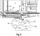
- a circulating pump PU is shown in dash-dot lines as a component of a liquid circulation system which is provided for the loading of washware with washing liquor liquid. It is connected on the inlet side via a suction pipeline SL, which is also shown in dot-dash lines, to the pump pot or liquid collection area 21 of the bottom of the washing container 2, from where it draws in washing liquid which collects during pump operation. On the output side, it is connected to a water diverter WS, also shown in dash-dotted lines, via a pressure pipeline PL, also shown in broken lines.
- a first outlet pipeline L1 leads from the water switch WS to the lower spray arm 17 (see Figure 5 ), a second outlet pipeline L2 to branch 19, which leads via the riser 18 to the upper spray arm and / or another upper spray device such as a roof shower, which here in the Figures 1 - 5 have been omitted for the sake of clarity.
- the Pumping power of the circulation pump PU can be set by means of a control device of the dishwasher 1. This control device is in the Figure 5 additionally indicated by dash-dotted lines and labeled SG.
- the control / regulating device SG can change the positions of the water switch WS with regard to the fluidic coupling of the outlet pipelines L1, L2 to the pressure pipe PL of the circulation pump PU, depending on the desired washing mode in the respective program step of a dishwashing program.
- the outflow pipe line L1 to the lower spray arm 17 can be fluidly connected to the pressure pipe PL of the circulation pump PU by means of a correspondingly selective water switch position.
- only the outlet pipe line L2 to branch 19 can be fluidly connected to the pressure pipe PL of the circulation pump PU by means of a correspondingly selective water switch position.
- so-called interchangeable arm spraying is also possible by continuously changing the water switch position for alternately coupling the pressure pipe PL to the first or second outlet pipeline L1, L2 (in addition to other, further setting options) in the respective program step.
- the WS water switch in the liquid circulation system can also be dispensed with entirely.
- the pressure pipe PL is preferably connected to the two outlet pipes L1, L2 simultaneously via a Y connecting pipe section.
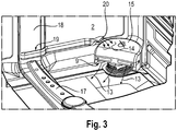
- the own pipe system 16 can run optically inconspicuous, at least in regions, behind a rear wall of the washing compartment 2. Here, laying from the covered riser pipe 18 is shown in the visible area of the washing compartment 2.
- blow-out opening 9 in a lower corner region of the washing compartment 2 near the rear wall thereof.
- an application end 20 of the pipe system 16 for the application of coolant is directed at the blow-out opening 9, in particular a blow-out cap 15 enclosing this, which is made, for example, of stainless steel.
- the application end 20 of the pipe system 16 for the application of coolant can be narrowed in a nozzle-like manner, as here, for example, in FIG Figure 3 is clearly recognizable.
- the loading end 20 can be aligned such that it is about 1 to 2 cm above the cap 15 at its edge and floods the entire top of the cap 15 with its water jet 14.
- the respective rinse cycle comprises one or more partial rinse cycles or rinse steps such as, for example, a pre-rinse cycle, cleaning cycle, intermediate rinse cycle and rinse cycle, in which each washing or rinsing liquid ("rinsing liquor") is sprayed onto the one or more by means of one or more spray devices in the rinsing container several recordings, in particular crockery baskets, is sprayed.
- a circulation pump is provided, which sucks the washing liquid converging there from a pump pot or liquid collection area in the bottom of the washing container via a suction line and pumps it under pressure into one or more supply pipes into the one or more spray devices. Possibly.
- a partial rinse such as the pre-rinse and / or the intermediate rinse can be omitted.
- a dishwashing program can also be provided, which has only a single wash cycle, such as, for example, only the rinse cycle for loading washware with washing liquid, in particular rinse liquid.
- the last step in the respective rinsing cycle is expediently a drying phase in which moisture from the rinsing container 2 is adsorbed in the sorption drying device 12. It is therefore advantageous if the desorption phase of the water-absorbent agent is within a rinse cycle before a drying phase of the dishes associated with adsorption of the water-absorbent agent. For example, the desorption phase can be directly before drying.
- the dishwasher 1 is therefore also a sterilizer usable. For this, there is also no need to precede a partial rinse with washing liquid, but dishes that have been washed by hand, for example, can only be put into the dishwasher 1 for sterilization and drying.
- a special dishwashing program can expediently be provided, which only carries out the drying cycle and / or the sterilization cycle.
- a UV lamp or an ozone generator can also be provided for sterilization.
- All processes of desorption, adsorption and other phases can be controlled, in particular, via a sequence program, in which, for example, pure sterilization can also be set.
- An optional program design can also be possible, for example in noise-sensitive programs (for example night program) with blow-off cap cooling and in programs which are sensitive to the purge performance, with the cooling of the blow-out cap 15 over the entire spray system.
- noise-sensitive programs for example night program
- programs which are sensitive to the purge performance with the cooling of the blow-out cap 15 over the entire spray system.
- the invention results in an additional noise reduction.
- a very defined loading and cooling of the blow-out cap 15 is possible.
- the cooling cannot be covered by loading the washing compartment 2.
- Retrofitting is possible due to the integration of the pipe system 16 and the small length behind the branch 19. There is no major impact on the rest of the series.
- Figure 6 shows a schematic speed / time diagram for setting the speed of the pump during the course of a rinse cycle SG.
- the rinse cycle SG here includes, for example, the liquid-carrying partial rinse cycles pre-rinse VG, cleaning RG, intermediate rinse ZG and rinse-off KG as well as the final drying cycle TG. It lasts from the start time tA to the end time tE.
- a partial or complete pumping out of the rinsing liquid from the rinsing container is expediently carried out by means of an emptying pump, which is omitted in the figures for the sake of clarity.
- the rinsing liquid is pumped out of the rinsing container as completely as possible.
- washing liquid is sprayed onto the items to be washed by means of the lower and / or upper spraying device.
- the desorption phase KB can preferably be carried out immediately after the end of the spray operation of the rinse aid KG before the drying stage TG.
- the circulation pump PU works with a first set speed n SP during the partial rinse cycles VG, RG, ZG and with a lower second set speed n DE during the desorption phase KB during the rinse cycle KG, which takes place partially or completely during its final section. So there are n SP > n DE .
- the water switch WS is expediently brought into a position by the control device SG via the signal line CL1 such that its outlet pipe L1 is closed to the lower spray arm 17 and only the outlet pipe L2 to the branch 19 is open.
- the speed of the circulation pump is preferably set by the control device SG via the signal line CL2 in such a way that the pump pressure of the circulation pump PU is not sufficient for rinsing liquid to rise above branch 19 into the riser pipe 18 to the upper spray device (s), but instead essentially only flows into the specially provided, separate, in particular here essentially horizontally running, cooling tube 16 and exits from its end opening 20 and flows from there onto the cap 15.
- the outlet end 20 of the cooling tube 16 is preferably somewhat higher than the cap 15, so that the outflowing cooling liquid can flow over it from above. This ensures effective cooling of the cap 15 and thus the blow-out opening 9 during the desorption phase.
- the area around the blow-out opening, in particular the cap 15 above the blow-out opening 9, and thus the air flowing out of the blow-out opening 9 during the desorption phase can be cooled with the rinse aid liquid in a targeted manner via the specially provided pipe system 16.
- the air flowing out of the blow-out opening 9 during the desorption phase preferably only has a temperature of less than 70 ° C. Due to the reduced speed n DE of the circulation pump during the desorption phase KB, in particular the noise of the dishwasher can be reduced during the desorption phase.
- the spray operation takes place in the rinse cycle, for example at a reduced speed n of the circulation pump PU, which essentially corresponds to the speed n DE in the subsequent desorption phase KB (without spray operation).
- a specific “only drying” dishwashing program in which the partial rinse cycles VG, RG, ZG, KG are omitted and only one desorption phase and the subsequent drying cycle TG with the contained adsorption phase are present.
- the outlet opening 9 is expediently cooled by means of the specially provided coolant admission, here through the pipe system 16, as explained above.
- the rinsing tank is expediently given clear fresh water for the desorption phase as a coolant, e.g. fed to the dishwasher via the water supply system.
- no spray operation is expediently carried out by the one or more spray devices present in the washing container.
- the speed of the circulation pump is then preferably selected such that the cooling liquid, here rinse liquid, cannot rise above the branch 19 into the riser 18 to the one or more upper spray devices, but only flows into the cooling pipe 16 and from there onto the Cap 15 flows over the discharge opening 9.
- the cooling liquid here rinse liquid
- the outlet opening can be cooled with the rinse aid liquid from the rinse cycle during the desorption phase before it is finally pumped off before the start of the drying cycle.
Landscapes
- Engineering & Computer Science (AREA)
- Water Supply & Treatment (AREA)
- Washing And Drying Of Tableware (AREA)
Claims (15)
- Lave-vaisselle (1), en particulier lave-vaisselle ménager, avec une cuve de lavage (2) pour le lavage de vaisselle, de verres, de couverts ou d'élément semblable à laver et avec un agent d'un dispositif de séchage par sorption absorbant de l'eau par phases, en particulier sur la base de zéolithe, dans lequel durant au moins une phase de désorption de l'agent absorbant de l'eau de l'air chauffé et contenant de l'eau peut être introduit via au moins un orifice de soufflage (9) dans la cuve de lavage (2), et avec un ou plusieurs dispositifs de pulvérisation disposés dans la cuve de lavage (2), en particulier des bras de pulvérisation rotatifs durant le lavage, servant à alimenter la vaisselle en liquide de lavage resp. en bain de lavage, caractérisé en ce que l'orifice de soufflage (9) peut être refroidi via une alimentation en fluide de refroidissement spécialement prévue, distincte, et dirigée vers l'orifice de soufflage (9), laquelle est prévue outre le ou les dispositif(s) de pulvérisation dans la cuve de lavage, ou en ce que l'orifice de soufflage (9) peut être refroidi via une alimentation en fluide de refroidissement spécialement prévue et dirigée vers l'orifice de soufflage (9), constituée par un bras de pulvérisation logé en rotation, cependant placé pour la durée essentielle de la phase désorption dans une position de réfrigération spécifique de telle sorte qu'un jet de pulvérisation de fluide issu d'au moins une buse du bras de pulvérisation est dirigé sur l'orifice de soufflage (9) et/ou son environnement pour la durée essentielle de la phase de désorption.
- Lave-vaisselle (1) selon la revendication 1, caractérisé en ce que l'alimentation en fluide de refroidissement peut s'effectuer indépendamment de l'alimentation de la vaisselle.
- Lave-vaisselle selon la revendication 2, caractérisé en ce que le fluide de refroidissement utilisé est l'eau.
- Lave-vaisselle (1) selon l'une des revendications 1 à 3, caractérisé en ce que l'eau dans le lave-vaisselle (1) peut être mise en circulation et utilisée plusieurs fois comme fluide de refroidissement.
- Lave-vaisselle (1) selon l'une des revendications 1 à 4, caractérisé en ce que l'alimentation en fluide de refroidissement peut être exploitée sans introduction concomitante de bain de lavage dans la cuve de lavage (2).
- Lave-vaisselle (1) selon l'une des revendications 1 à 5, caractérisé en ce que l'alimentation en fluide de refroidissement dispose d'une tuyauterie propre (16), au moins partiellement indépendante d'une tuyauterie prévue pour l'alimentation de la vaisselle.
- Lave-vaisselle (1) selon la revendication 6, caractérisé en ce que la tuyauterie propre (16) bifurque en une bifurcation (19) de la tuyauterie prévue pour l'alimentation de la vaisselle.
- Lave-vaisselle (1) selon la revendication 7, caractérisé en ce que la tuyauterie propre (16) est uniquement alimentée en présence d'une faible vitesse d'écoulement de l'eau et en ce que l'eau passe devant la bifurcation (19) en présence d'une vitesse d'écoulement de l'eau élevée.
- Lave-vaisselle (1) selon l'une des revendications 6 à 8, caractérisé en ce que la tuyauterie propre (16) s'étend au moins par sections derrière une paroi arrière de la cuve de lavage (2).
- Lave-vaisselle (1) selon l'une des revendications 1 à 9, caractérisé en ce qu'un orifice de soufflage (9) se trouve dans une zone angulaire inférieure de la cuve de lavage (2) à proximité de sa paroi arrière.
- Lave-vaisselle (1) selon l'une des revendications 1 à 10, caractérisé en ce qu'une extrémité d'alimentation (20) de la tuyauterie (16) pour l'alimentation en fluide de refroidissement est dirigée sur l'orifice de soufflage (9), en particulier sur un capuchon de soufflage (15) l'englobant.
- Lave-vaisselle (1) selon la revendication 11, caractérisé en ce que l'extrémité d'alimentation (20) de la tuyauterie (16) est rétrécie à la façon d'une buse pour l'alimentation en fluide de refroidissement.
- Lave-vaisselle (1) selon l'une des revendications 1 à 12, caractérisé en ce que la phase de désorption de l'agent absorbant est positionnée au sein d'un cycle de lavage avant une phase de séchage accompagnant une adsorption de l'agent absorbant.
- Lave-vaisselle (1) selon l'une des revendications précédentes, caractérisé en ce que les processus de désorption, d'adsorption et les autres phases sont commandés via un programme séquentiel.
- Lave-vaisselle (1) selon l'une des revendications précédentes, caractérisé en ce que celui-ci constitue en double fonction aussi un stérilisateur pour la vaisselle.
Applications Claiming Priority (2)
| Application Number | Priority Date | Filing Date | Title |
|---|---|---|---|
| DE102015212888.1A DE102015212888A1 (de) | 2015-07-09 | 2015-07-09 | Geschirrspülmaschine mit einer Trocknungseinrichtung |
| PCT/EP2016/059868 WO2017005389A1 (fr) | 2015-07-09 | 2016-05-03 | Lave-vaisselle pourvu d'un système de sechage |
Publications (2)
| Publication Number | Publication Date |
|---|---|
| EP3319501A1 EP3319501A1 (fr) | 2018-05-16 |
| EP3319501B1 true EP3319501B1 (fr) | 2020-04-15 |
Family
ID=55862805
Family Applications (1)
| Application Number | Title | Priority Date | Filing Date |
|---|---|---|---|
| EP16719881.1A Active EP3319501B1 (fr) | 2015-07-09 | 2016-05-03 | Lave-vaisselle pourvu d'un système de séchage |
Country Status (3)
| Country | Link |
|---|---|
| EP (1) | EP3319501B1 (fr) |
| DE (1) | DE102015212888A1 (fr) |
| WO (1) | WO2017005389A1 (fr) |
Families Citing this family (2)
| Publication number | Priority date | Publication date | Assignee | Title |
|---|---|---|---|---|
| AU2019281358A1 (en) | 2018-06-03 | 2021-01-07 | Lamkap Bio Beta Ltd. | Bispecific antibodies against CEACAM5 and CD47 |
| EP3831849A1 (fr) | 2019-12-02 | 2021-06-09 | LamKap Bio beta AG | Anticorps bispécifiques contre ceacam5 et cd47 |
Family Cites Families (4)
| Publication number | Priority date | Publication date | Assignee | Title |
|---|---|---|---|---|
| DE10353774A1 (de) * | 2003-07-30 | 2005-02-24 | BSH Bosch und Siemens Hausgeräte GmbH | Geschirrspülmaschine |
| DE102008043554A1 (de) | 2008-11-07 | 2010-05-12 | BSH Bosch und Siemens Hausgeräte GmbH | Verfahren zum Betreiben eines Geschirrspülmaschine |
| DE102008039885A1 (de) * | 2008-08-27 | 2010-04-08 | BSH Bosch und Siemens Hausgeräte GmbH | Geschirrspülmaschine mit Sorptionstrockenvorrichtung |
| DE102013223940B3 (de) * | 2013-11-22 | 2015-04-02 | BSH Bosch und Siemens Hausgeräte GmbH | Geschirrspülmaschine mit Sterilisationsmöglichkeit |
-
2015
- 2015-07-09 DE DE102015212888.1A patent/DE102015212888A1/de not_active Withdrawn
-
2016
- 2016-05-03 EP EP16719881.1A patent/EP3319501B1/fr active Active
- 2016-05-03 WO PCT/EP2016/059868 patent/WO2017005389A1/fr active Application Filing
Non-Patent Citations (1)
| Title |
|---|
| None * |
Also Published As
| Publication number | Publication date |
|---|---|
| WO2017005389A1 (fr) | 2017-01-12 |
| DE102015212888A1 (de) | 2017-01-12 |
| EP3319501A1 (fr) | 2018-05-16 |
Similar Documents
| Publication | Publication Date | Title |
|---|---|---|
| DE102015203132B4 (de) | Spülmaschine in Gestalt einer als Programmautomat ausgebildeten gewerblichen Utensilien- oder Geschirrspülmaschine | |
| DE102006025152B4 (de) | Geschirrspülmaschine und Steuerungsverfahren dafür | |
| DE102006025150B4 (de) | Geschirrspülmaschine | |
| DE102012025591B4 (de) | Verfahren zum Betreiben eines Geschirrspülers mit geschlossenem Kondenserkreis | |
| DE102015111994B4 (de) | Spülmaschine in Gestalt einer als Programmautomat ausgebildeten gewerblichen Utensilien- oder Geschirrspülmaschine | |
| WO2010009890A1 (fr) | Lave-vaisselle présentant deux circuits de circulation | |
| WO2019015964A1 (fr) | Lave-vaisselle comprenant une ou plusieurs unités de chargement | |
| DE102010061342A1 (de) | Geschirrspüler mit gemeinsam genutzter Heizeinrichtung | |
| EP2473085B1 (fr) | Lave-vaisselle doté d'un réservoir et procédé de préchauffage associé | |
| WO2008113473A1 (fr) | Appareil automatique de nettoyage à énergie optimisée | |
| EP1055389A2 (fr) | Lave-vaisselle commandé par programme avec dispositif pour sécher la vaisselle | |
| DE102008014921A1 (de) | Transportspülmaschine sowie Verfahren zum Betreiben einer Transportspülmaschine | |
| EP2420175A2 (fr) | Lave-vaisselle doté d'un programme de rinçage adaptable manuellement | |
| DE102012207565A1 (de) | Verfahren zum Betreiben einer als Programmautomat ausgebildeten Spülmaschine sowie entsprechende Spülmaschine | |
| DE102015111883A1 (de) | Spülmaschine in Gestalt einer als Programmautomat ausgebildeten gewerblichen Utensilien- oder Geschirrspülmaschine | |
| DE102014105830A1 (de) | Geschirrspüler | |
| DE102004060947A1 (de) | Haushalts-Geschirrspülmaschine und Verfahren zum Betreiben derselben | |
| EP3319501B1 (fr) | Lave-vaisselle pourvu d'un système de séchage | |
| EP2352411B1 (fr) | Procédé pour faire fonctionner un lave-vaisselle | |
| DE102011083179B4 (de) | Transportspülmaschine und Verfahren zum Betreiben einer Transportspülmaschine | |
| EP2326234B1 (fr) | Procédé de fonctionnement d'un lave-vaisselle | |
| EP2315546B1 (fr) | Lave-vaisselle présentant deux circuits de circulation | |
| EP2352410B1 (fr) | Lave-vaisselle et procédé pour chauffer le liquide | |
| DE102023118436B3 (de) | Gewerbliche spülmaschine mit einem trocknungsmodul, verfahren zum betreiben einer solchen spülmaschine sowie trocknungsmodul für eine spülmaschine | |
| DE102014101724A1 (de) | Verfahren und Vorrichtung für Geschirrspüler mit gemeinsamem Heizungselement für mehrere Behandlungskammern |
Legal Events
| Date | Code | Title | Description |
|---|---|---|---|
| STAA | Information on the status of an ep patent application or granted ep patent |
Free format text: STATUS: THE INTERNATIONAL PUBLICATION HAS BEEN MADE |
|
| PUAI | Public reference made under article 153(3) epc to a published international application that has entered the european phase |
Free format text: ORIGINAL CODE: 0009012 |
|
| STAA | Information on the status of an ep patent application or granted ep patent |
Free format text: STATUS: REQUEST FOR EXAMINATION WAS MADE |
|
| 17P | Request for examination filed |
Effective date: 20180209 |
|
| AK | Designated contracting states |
Kind code of ref document: A1 Designated state(s): AL AT BE BG CH CY CZ DE DK EE ES FI FR GB GR HR HU IE IS IT LI LT LU LV MC MK MT NL NO PL PT RO RS SE SI SK SM TR |
|
| AX | Request for extension of the european patent |
Extension state: BA ME |
|
| DAV | Request for validation of the european patent (deleted) | ||
| DAX | Request for extension of the european patent (deleted) | ||
| STAA | Information on the status of an ep patent application or granted ep patent |
Free format text: STATUS: EXAMINATION IS IN PROGRESS |
|
| 17Q | First examination report despatched |
Effective date: 20190510 |
|
| GRAP | Despatch of communication of intention to grant a patent |
Free format text: ORIGINAL CODE: EPIDOSNIGR1 |
|
| STAA | Information on the status of an ep patent application or granted ep patent |
Free format text: STATUS: GRANT OF PATENT IS INTENDED |
|
| INTG | Intention to grant announced |
Effective date: 20191211 |
|
| GRAS | Grant fee paid |
Free format text: ORIGINAL CODE: EPIDOSNIGR3 |
|
| GRAA | (expected) grant |
Free format text: ORIGINAL CODE: 0009210 |
|
| STAA | Information on the status of an ep patent application or granted ep patent |
Free format text: STATUS: THE PATENT HAS BEEN GRANTED |
|
| AK | Designated contracting states |
Kind code of ref document: B1 Designated state(s): AL AT BE BG CH CY CZ DE DK EE ES FI FR GB GR HR HU IE IS IT LI LT LU LV MC MK MT NL NO PL PT RO RS SE SI SK SM TR |
|
| REG | Reference to a national code |
Ref country code: CH Ref legal event code: EP |
|
| REG | Reference to a national code |
Ref country code: DE Ref legal event code: R096 Ref document number: 502016009549 Country of ref document: DE |
|
| REG | Reference to a national code |
Ref country code: IE Ref legal event code: FG4D Free format text: LANGUAGE OF EP DOCUMENT: GERMAN |
|
| REG | Reference to a national code |
Ref country code: AT Ref legal event code: REF Ref document number: 1256320 Country of ref document: AT Kind code of ref document: T Effective date: 20200515 |
|
| REG | Reference to a national code |
Ref country code: NL Ref legal event code: MP Effective date: 20200415 |
|
| REG | Reference to a national code |
Ref country code: LT Ref legal event code: MG4D |
|
| PG25 | Lapsed in a contracting state [announced via postgrant information from national office to epo] |
Ref country code: LT Free format text: LAPSE BECAUSE OF FAILURE TO SUBMIT A TRANSLATION OF THE DESCRIPTION OR TO PAY THE FEE WITHIN THE PRESCRIBED TIME-LIMIT Effective date: 20200415 Ref country code: NL Free format text: LAPSE BECAUSE OF FAILURE TO SUBMIT A TRANSLATION OF THE DESCRIPTION OR TO PAY THE FEE WITHIN THE PRESCRIBED TIME-LIMIT Effective date: 20200415 Ref country code: NO Free format text: LAPSE BECAUSE OF FAILURE TO SUBMIT A TRANSLATION OF THE DESCRIPTION OR TO PAY THE FEE WITHIN THE PRESCRIBED TIME-LIMIT Effective date: 20200715 Ref country code: PT Free format text: LAPSE BECAUSE OF FAILURE TO SUBMIT A TRANSLATION OF THE DESCRIPTION OR TO PAY THE FEE WITHIN THE PRESCRIBED TIME-LIMIT Effective date: 20200817 Ref country code: SE Free format text: LAPSE BECAUSE OF FAILURE TO SUBMIT A TRANSLATION OF THE DESCRIPTION OR TO PAY THE FEE WITHIN THE PRESCRIBED TIME-LIMIT Effective date: 20200415 Ref country code: GR Free format text: LAPSE BECAUSE OF FAILURE TO SUBMIT A TRANSLATION OF THE DESCRIPTION OR TO PAY THE FEE WITHIN THE PRESCRIBED TIME-LIMIT Effective date: 20200716 Ref country code: IS Free format text: LAPSE BECAUSE OF FAILURE TO SUBMIT A TRANSLATION OF THE DESCRIPTION OR TO PAY THE FEE WITHIN THE PRESCRIBED TIME-LIMIT Effective date: 20200815 Ref country code: FI Free format text: LAPSE BECAUSE OF FAILURE TO SUBMIT A TRANSLATION OF THE DESCRIPTION OR TO PAY THE FEE WITHIN THE PRESCRIBED TIME-LIMIT Effective date: 20200415 |
|
| PG25 | Lapsed in a contracting state [announced via postgrant information from national office to epo] |
Ref country code: RS Free format text: LAPSE BECAUSE OF FAILURE TO SUBMIT A TRANSLATION OF THE DESCRIPTION OR TO PAY THE FEE WITHIN THE PRESCRIBED TIME-LIMIT Effective date: 20200415 Ref country code: HR Free format text: LAPSE BECAUSE OF FAILURE TO SUBMIT A TRANSLATION OF THE DESCRIPTION OR TO PAY THE FEE WITHIN THE PRESCRIBED TIME-LIMIT Effective date: 20200415 Ref country code: LV Free format text: LAPSE BECAUSE OF FAILURE TO SUBMIT A TRANSLATION OF THE DESCRIPTION OR TO PAY THE FEE WITHIN THE PRESCRIBED TIME-LIMIT Effective date: 20200415 Ref country code: BG Free format text: LAPSE BECAUSE OF FAILURE TO SUBMIT A TRANSLATION OF THE DESCRIPTION OR TO PAY THE FEE WITHIN THE PRESCRIBED TIME-LIMIT Effective date: 20200715 |
|
| PG25 | Lapsed in a contracting state [announced via postgrant information from national office to epo] |
Ref country code: AL Free format text: LAPSE BECAUSE OF FAILURE TO SUBMIT A TRANSLATION OF THE DESCRIPTION OR TO PAY THE FEE WITHIN THE PRESCRIBED TIME-LIMIT Effective date: 20200415 |
|
| REG | Reference to a national code |
Ref country code: DE Ref legal event code: R097 Ref document number: 502016009549 Country of ref document: DE |
|
| PG25 | Lapsed in a contracting state [announced via postgrant information from national office to epo] |
Ref country code: CH Free format text: LAPSE BECAUSE OF NON-PAYMENT OF DUE FEES Effective date: 20200531 Ref country code: LI Free format text: LAPSE BECAUSE OF NON-PAYMENT OF DUE FEES Effective date: 20200531 Ref country code: RO Free format text: LAPSE BECAUSE OF FAILURE TO SUBMIT A TRANSLATION OF THE DESCRIPTION OR TO PAY THE FEE WITHIN THE PRESCRIBED TIME-LIMIT Effective date: 20200415 Ref country code: CZ Free format text: LAPSE BECAUSE OF FAILURE TO SUBMIT A TRANSLATION OF THE DESCRIPTION OR TO PAY THE FEE WITHIN THE PRESCRIBED TIME-LIMIT Effective date: 20200415 Ref country code: ES Free format text: LAPSE BECAUSE OF FAILURE TO SUBMIT A TRANSLATION OF THE DESCRIPTION OR TO PAY THE FEE WITHIN THE PRESCRIBED TIME-LIMIT Effective date: 20200415 Ref country code: MC Free format text: LAPSE BECAUSE OF FAILURE TO SUBMIT A TRANSLATION OF THE DESCRIPTION OR TO PAY THE FEE WITHIN THE PRESCRIBED TIME-LIMIT Effective date: 20200415 Ref country code: DK Free format text: LAPSE BECAUSE OF FAILURE TO SUBMIT A TRANSLATION OF THE DESCRIPTION OR TO PAY THE FEE WITHIN THE PRESCRIBED TIME-LIMIT Effective date: 20200415 Ref country code: SM Free format text: LAPSE BECAUSE OF FAILURE TO SUBMIT A TRANSLATION OF THE DESCRIPTION OR TO PAY THE FEE WITHIN THE PRESCRIBED TIME-LIMIT Effective date: 20200415 Ref country code: IT Free format text: LAPSE BECAUSE OF FAILURE TO SUBMIT A TRANSLATION OF THE DESCRIPTION OR TO PAY THE FEE WITHIN THE PRESCRIBED TIME-LIMIT Effective date: 20200415 Ref country code: EE Free format text: LAPSE BECAUSE OF FAILURE TO SUBMIT A TRANSLATION OF THE DESCRIPTION OR TO PAY THE FEE WITHIN THE PRESCRIBED TIME-LIMIT Effective date: 20200415 |
|
| PLBE | No opposition filed within time limit |
Free format text: ORIGINAL CODE: 0009261 |
|
| STAA | Information on the status of an ep patent application or granted ep patent |
Free format text: STATUS: NO OPPOSITION FILED WITHIN TIME LIMIT |
|
| PG25 | Lapsed in a contracting state [announced via postgrant information from national office to epo] |
Ref country code: PL Free format text: LAPSE BECAUSE OF FAILURE TO SUBMIT A TRANSLATION OF THE DESCRIPTION OR TO PAY THE FEE WITHIN THE PRESCRIBED TIME-LIMIT Effective date: 20200415 Ref country code: SK Free format text: LAPSE BECAUSE OF FAILURE TO SUBMIT A TRANSLATION OF THE DESCRIPTION OR TO PAY THE FEE WITHIN THE PRESCRIBED TIME-LIMIT Effective date: 20200415 |
|
| REG | Reference to a national code |
Ref country code: BE Ref legal event code: MM Effective date: 20200531 |
|
| 26N | No opposition filed |
Effective date: 20210118 |
|
| GBPC | Gb: european patent ceased through non-payment of renewal fee |
Effective date: 20200715 |
|
| PG25 | Lapsed in a contracting state [announced via postgrant information from national office to epo] |
Ref country code: LU Free format text: LAPSE BECAUSE OF NON-PAYMENT OF DUE FEES Effective date: 20200503 |
|
| PG25 | Lapsed in a contracting state [announced via postgrant information from national office to epo] |
Ref country code: FR Free format text: LAPSE BECAUSE OF NON-PAYMENT OF DUE FEES Effective date: 20200615 Ref country code: GB Free format text: LAPSE BECAUSE OF NON-PAYMENT OF DUE FEES Effective date: 20200715 Ref country code: IE Free format text: LAPSE BECAUSE OF NON-PAYMENT OF DUE FEES Effective date: 20200503 |
|
| PG25 | Lapsed in a contracting state [announced via postgrant information from national office to epo] |
Ref country code: BE Free format text: LAPSE BECAUSE OF NON-PAYMENT OF DUE FEES Effective date: 20200531 Ref country code: SI Free format text: LAPSE BECAUSE OF FAILURE TO SUBMIT A TRANSLATION OF THE DESCRIPTION OR TO PAY THE FEE WITHIN THE PRESCRIBED TIME-LIMIT Effective date: 20200415 |
|
| PG25 | Lapsed in a contracting state [announced via postgrant information from national office to epo] |
Ref country code: TR Free format text: LAPSE BECAUSE OF FAILURE TO SUBMIT A TRANSLATION OF THE DESCRIPTION OR TO PAY THE FEE WITHIN THE PRESCRIBED TIME-LIMIT Effective date: 20200415 Ref country code: MT Free format text: LAPSE BECAUSE OF FAILURE TO SUBMIT A TRANSLATION OF THE DESCRIPTION OR TO PAY THE FEE WITHIN THE PRESCRIBED TIME-LIMIT Effective date: 20200415 Ref country code: CY Free format text: LAPSE BECAUSE OF FAILURE TO SUBMIT A TRANSLATION OF THE DESCRIPTION OR TO PAY THE FEE WITHIN THE PRESCRIBED TIME-LIMIT Effective date: 20200415 |
|
| PG25 | Lapsed in a contracting state [announced via postgrant information from national office to epo] |
Ref country code: MK Free format text: LAPSE BECAUSE OF FAILURE TO SUBMIT A TRANSLATION OF THE DESCRIPTION OR TO PAY THE FEE WITHIN THE PRESCRIBED TIME-LIMIT Effective date: 20200415 |
|
| REG | Reference to a national code |
Ref country code: AT Ref legal event code: MM01 Ref document number: 1256320 Country of ref document: AT Kind code of ref document: T Effective date: 20210503 |
|
| PG25 | Lapsed in a contracting state [announced via postgrant information from national office to epo] |
Ref country code: AT Free format text: LAPSE BECAUSE OF NON-PAYMENT OF DUE FEES Effective date: 20210503 |
|
| PGFP | Annual fee paid to national office [announced via postgrant information from national office to epo] |
Ref country code: DE Payment date: 20240531 Year of fee payment: 9 |