EP3319501B1 - Dishwasher having a drying device - Google Patents
Dishwasher having a drying device Download PDFInfo
- Publication number
- EP3319501B1 EP3319501B1 EP16719881.1A EP16719881A EP3319501B1 EP 3319501 B1 EP3319501 B1 EP 3319501B1 EP 16719881 A EP16719881 A EP 16719881A EP 3319501 B1 EP3319501 B1 EP 3319501B1
- Authority
- EP
- European Patent Office
- Prior art keywords
- dishwasher
- water
- coolant
- items
- pipe system
- Prior art date
- Legal status (The legal status is an assumption and is not a legal conclusion. Google has not performed a legal analysis and makes no representation as to the accuracy of the status listed.)
- Active
Links
- 238000001035 drying Methods 0.000 title claims description 53
- 238000003795 desorption Methods 0.000 claims description 75
- 239000007921 spray Substances 0.000 claims description 61
- 238000005406 washing Methods 0.000 claims description 61
- XLYOFNOQVPJJNP-UHFFFAOYSA-N water Substances O XLYOFNOQVPJJNP-UHFFFAOYSA-N 0.000 claims description 59
- 238000001179 sorption measurement Methods 0.000 claims description 49
- 239000002826 coolant Substances 0.000 claims description 45
- 239000007788 liquid Substances 0.000 claims description 44
- 238000005507 spraying Methods 0.000 claims description 12
- 238000004140 cleaning Methods 0.000 claims description 9
- 230000008569 process Effects 0.000 claims description 5
- 229910021536 Zeolite Inorganic materials 0.000 claims description 4
- HNPSIPDUKPIQMN-UHFFFAOYSA-N dioxosilane;oxo(oxoalumanyloxy)alumane Chemical compound O=[Si]=O.O=[Al]O[Al]=O HNPSIPDUKPIQMN-UHFFFAOYSA-N 0.000 claims description 4
- 239000010457 zeolite Substances 0.000 claims description 4
- 239000011521 glass Substances 0.000 claims description 3
- 238000000034 method Methods 0.000 claims description 3
- 238000010521 absorption reaction Methods 0.000 claims 1
- 230000009977 dual effect Effects 0.000 claims 1
- 238000001816 cooling Methods 0.000 description 25
- 239000000463 material Substances 0.000 description 16
- 230000001954 sterilising effect Effects 0.000 description 8
- 238000011068 loading method Methods 0.000 description 7
- 238000004659 sterilization and disinfection Methods 0.000 description 7
- 238000010438 heat treatment Methods 0.000 description 6
- 230000008901 benefit Effects 0.000 description 5
- 238000011161 development Methods 0.000 description 5
- 230000018109 developmental process Effects 0.000 description 5
- 239000002250 absorbent Substances 0.000 description 4
- 238000005086 pumping Methods 0.000 description 4
- 239000006096 absorbing agent Substances 0.000 description 3
- 239000003795 chemical substances by application Substances 0.000 description 3
- 230000008878 coupling Effects 0.000 description 3
- 238000010168 coupling process Methods 0.000 description 3
- 238000005859 coupling reaction Methods 0.000 description 3
- 239000003599 detergent Substances 0.000 description 3
- 238000011010 flushing procedure Methods 0.000 description 3
- 238000010186 staining Methods 0.000 description 3
- CBENFWSGALASAD-UHFFFAOYSA-N Ozone Chemical compound [O-][O+]=O CBENFWSGALASAD-UHFFFAOYSA-N 0.000 description 2
- 239000000110 cooling liquid Substances 0.000 description 2
- 238000013461 design Methods 0.000 description 2
- 238000010586 diagram Methods 0.000 description 2
- 239000013505 freshwater Substances 0.000 description 2
- 230000009467 reduction Effects 0.000 description 2
- 238000006424 Flood reaction Methods 0.000 description 1
- 230000004308 accommodation Effects 0.000 description 1
- 230000009471 action Effects 0.000 description 1
- 230000006978 adaptation Effects 0.000 description 1
- 239000003463 adsorbent Substances 0.000 description 1
- 238000007605 air drying Methods 0.000 description 1
- 230000008859 change Effects 0.000 description 1
- 239000012459 cleaning agent Substances 0.000 description 1
- 238000009833 condensation Methods 0.000 description 1
- 230000005494 condensation Effects 0.000 description 1
- 238000010411 cooking Methods 0.000 description 1
- 230000001419 dependent effect Effects 0.000 description 1
- 239000002274 desiccant Substances 0.000 description 1
- 238000004851 dishwashing Methods 0.000 description 1
- 239000012530 fluid Substances 0.000 description 1
- -1 for example Substances 0.000 description 1
- 230000017525 heat dissipation Effects 0.000 description 1
- 230000006872 improvement Effects 0.000 description 1
- 230000010354 integration Effects 0.000 description 1
- 230000003287 optical effect Effects 0.000 description 1
- 239000004033 plastic Substances 0.000 description 1
- 238000012545 processing Methods 0.000 description 1
- 238000010926 purge Methods 0.000 description 1
- 230000001105 regulatory effect Effects 0.000 description 1
- 238000009420 retrofitting Methods 0.000 description 1
- 239000002594 sorbent Substances 0.000 description 1
- 229910001220 stainless steel Inorganic materials 0.000 description 1
- 239000010935 stainless steel Substances 0.000 description 1
- 238000012549 training Methods 0.000 description 1
Images


Classifications
-
- A—HUMAN NECESSITIES
- A47—FURNITURE; DOMESTIC ARTICLES OR APPLIANCES; COFFEE MILLS; SPICE MILLS; SUCTION CLEANERS IN GENERAL
- A47L—DOMESTIC WASHING OR CLEANING; SUCTION CLEANERS IN GENERAL
- A47L15/00—Washing or rinsing machines for crockery or tableware
- A47L15/42—Details
- A47L15/48—Drying arrangements
- A47L15/481—Drying arrangements by using water absorbent materials, e.g. Zeolith
-
- A—HUMAN NECESSITIES
- A47—FURNITURE; DOMESTIC ARTICLES OR APPLIANCES; COFFEE MILLS; SPICE MILLS; SUCTION CLEANERS IN GENERAL
- A47L—DOMESTIC WASHING OR CLEANING; SUCTION CLEANERS IN GENERAL
- A47L15/00—Washing or rinsing machines for crockery or tableware
- A47L15/0018—Controlling processes, i.e. processes to control the operation of the machine characterised by the purpose or target of the control
- A47L15/0021—Regulation of operational steps within the washing processes, e.g. optimisation or improvement of operational steps depending from the detergent nature or from the condition of the crockery
- A47L15/0042—Desorption phases of reversibly dehydrogenated drying material, e.g. zeolite in a sorption drying system
-
- A—HUMAN NECESSITIES
- A47—FURNITURE; DOMESTIC ARTICLES OR APPLIANCES; COFFEE MILLS; SPICE MILLS; SUCTION CLEANERS IN GENERAL
- A47L—DOMESTIC WASHING OR CLEANING; SUCTION CLEANERS IN GENERAL
- A47L15/00—Washing or rinsing machines for crockery or tableware
- A47L15/0018—Controlling processes, i.e. processes to control the operation of the machine characterised by the purpose or target of the control
- A47L15/0052—Noise reduction
-
- A—HUMAN NECESSITIES
- A47—FURNITURE; DOMESTIC ARTICLES OR APPLIANCES; COFFEE MILLS; SPICE MILLS; SUCTION CLEANERS IN GENERAL
- A47L—DOMESTIC WASHING OR CLEANING; SUCTION CLEANERS IN GENERAL
- A47L15/00—Washing or rinsing machines for crockery or tableware
- A47L15/42—Details
- A47L15/4214—Water supply, recirculation or discharge arrangements; Devices therefor
- A47L15/4219—Water recirculation
-
- A—HUMAN NECESSITIES
- A47—FURNITURE; DOMESTIC ARTICLES OR APPLIANCES; COFFEE MILLS; SPICE MILLS; SUCTION CLEANERS IN GENERAL
- A47L—DOMESTIC WASHING OR CLEANING; SUCTION CLEANERS IN GENERAL
- A47L15/00—Washing or rinsing machines for crockery or tableware
- A47L15/42—Details
- A47L15/4236—Arrangements to sterilize or disinfect dishes or washing liquids
- A47L15/424—Arrangements to sterilize or disinfect dishes or washing liquids by using ozone
-
- A—HUMAN NECESSITIES
- A47—FURNITURE; DOMESTIC ARTICLES OR APPLIANCES; COFFEE MILLS; SPICE MILLS; SUCTION CLEANERS IN GENERAL
- A47L—DOMESTIC WASHING OR CLEANING; SUCTION CLEANERS IN GENERAL
- A47L15/00—Washing or rinsing machines for crockery or tableware
- A47L15/42—Details
- A47L15/4236—Arrangements to sterilize or disinfect dishes or washing liquids
- A47L15/4242—Arrangements to sterilize or disinfect dishes or washing liquids by using ultraviolet generators
-
- A—HUMAN NECESSITIES
- A47—FURNITURE; DOMESTIC ARTICLES OR APPLIANCES; COFFEE MILLS; SPICE MILLS; SUCTION CLEANERS IN GENERAL
- A47L—DOMESTIC WASHING OR CLEANING; SUCTION CLEANERS IN GENERAL
- A47L15/00—Washing or rinsing machines for crockery or tableware
- A47L15/42—Details
- A47L15/48—Drying arrangements
- A47L15/486—Blower arrangements
Definitions
- the invention relates to a dishwasher, in particular a domestic dishwasher, with a rinsing container for cleaning dishes, glasses, cutlery or similar items to be washed and with a phase-absorbing agent of a sorption drying device, in particular based on zeolite, with heated and water-containing during at least one desorption phase of the water-absorbing agent Air can be introduced into the washing compartment via at least one blow-out opening, according to the preamble of claim 1.
- sorption drying devices with a water-absorbing agent or reversibly dehydrable sorption material, such as, for example, zeolite.
- adsorption phase water-containing air is passed out of the washing compartment through the sorption drying device.
- the sorption material absorbs water from the air flowing through and / or water adheres to the sorption material so that the items to be washed can be dried in the washing container.
- this water is released again by the sorption material while the reversibly dehydratable sorbent is heated (by means of a heater) and blown out into the rinsing container.
- Such a desorption phase can take place, for example, before the actual drying cycle of the dishwashing cycle of a dishwashing program and has the advantage that residues of detergent, in particular rinse aid, remaining on the wash ware are diluted by the water vapor which is formed, and so staining is reduced.
- very high temperatures occur at the blow-out opening, for example above 200 ° C.
- items to be washed can be damaged in the vicinity of the blow-out opening, particularly if this is made of plastic.
- a crockery basket or another accommodation unit, such as a cutlery basket which accommodates items to be washed and which is in the vicinity of the blow-out opening.
- one or more wall surfaces of the washing compartment can become so hot, if necessary, that air flows from the blow-out opening so that touching them can be uncomfortable for an operator if the operator opens the door of the dishwasher during a desorption phase and into the washing compartment with one hand such a strongly heated wall part reaches.
- there may even be a risk of burns or scalding for an operator for example if the operator opens the door, thereby interrupting the washing cycle during a desorption phase, and the person reaches into the washing container and with too much heated items, too much heated parts a crockery basket and / or an excessively heated wall surface of the washing container comes into contact. Cooling of the blow-out opening is therefore sought.
- the invention is based on the problem of achieving an improvement here.
- blow-out opening can be cooled according to claim 1 by means of a specially provided, separate, and directed towards this coolant, it is not necessary that the blow-out opening is cooled by a spray device in the washing container, in particular a rotating spray arm, which is used for spraying Washware is provided in the wash container.
- a spray device in the washing container, in particular a rotating spray arm, which is used for spraying Washware is provided in the wash container.
- the spraying of liquid onto the items to be washed by the spraying device can thus advantageously be restricted or reduced or avoided entirely.
- the pumping capacity of a pump in particular a circulating pump, which is provided for conveying washing liquid or rinsing liquor to one or more spray devices arranged in the rinsing container, can do this be at least significantly reduced during the respective desorption phase, so that the pump noise of the pump is reduced accordingly and thus the operating noise of the dishwasher as a whole is reduced.
- the pump output can preferably be reduced by reducing the speed of the pump.
- the outlet temperature of the air which flows out of the blow-out opening is reduced compared to the desorption temperature of the air which it originally had in the respective desorption phase after flowing through the sorption unit of the sorption drying device which has the reversibly dehydratable sorption material.
- Desorbing the reversibly dehydratable sorption material is expediently brought about by heating it by means of an electrical heater assigned to the sorption unit and flowing air through it or by flowing hot air which (viewed in the direction of air flow) has previously been heated by means of an electrical heater.
- the air that leaves the sorption unit during a desorption phase has, in particular, a desorption temperature between 200 ° C. and 350 ° C.
- the air leaving the blow-out opening and entering the rinsing container now has an outlet temperature, which is preferably less than or equal to 70 ° C., by cooling the blow-out opening by means of the coolant application device according to the invention.
- At least one feed pipe for coolant, in particular coolant is additionally, i.e. Provided specifically for the one or more spray devices, in particular rotating spray arms in the washing mode, which serve to apply wash liquid or wash liquor to washware.
- the device for applying coolant can also be formed by a rotatably mounted spray arm, which, however, is brought into a specific stationary cooling position, preferably a rest or standstill position, for the majority of the desorption phase in such a way that a liquid spray jet from at least one nozzle of the spray arm on the discharge opening and / or its surroundings for the predominant duration of the desorption phase is directed.
- This spray arm which remains in the specific cooling position during the desorption phase, preferably "parked” or fixed there, then likewise forms a specially provided device for the targeted application of coolant to the blow-out opening.
- the device for the application of coolant can expediently be fluidly coupled to the existing liquid circulation circuit of the dishwasher, which usually comprises a circulation pump, one or more spray devices arranged in the washing container and associated liquid connection lines, and / or possibly a water switch.
- the speed of the circulation pump is preferably set lower during the respective desorption phase than during the washing or spraying operation of the dishwasher, in which washing liquid is sprayed onto the items to be cleaned from the one or more spray devices, in particular rotating spray arms.
- This has the advantage that the pump, which rotates more slowly during the desorption phase, can lower the noise level of the dishwasher during the desorption phase compared to the noise level during washing operation, in which the one or more spray devices spray washing liquid onto the items to be washed with the required spray pressure.
- the speed of the circulation pump can in particular be set in such a way that during the respective desorption phase essentially no more rinsing liquid (as in the rinsing mode) is sprayed onto the items to be washed by the one or more spray devices, but only from the device for applying coolant only to the items Blow-out opening coolant liquid, especially clear water, is discharged.
- a rinse cycle comprises one or more partial rinse cycles, such as pre-rinsing, cleaning, intermediate rinsing, rinsing, in which washing liquid is sprayed onto the items to be cleaned in the washing container by means of one or more spray devices.
- the desorption phase can expediently take place during at least one such partial rinse cycle. In particular, it is energy-saving if the desorption phase is carried out at least partially during a partial wash cycle in which the washing-up liquid and / or washware is heated to a minimum temperature is required.
- Such a partial rinse cycle with rinsing liquid to be heated can in particular be the cleaning cycle and / or rinse cycle.
- the desorption phase can either take place completely during only one partial rinse cycle or can be divided over several partial rinse cycles.
- the desorption phase takes place at least partially immediately before the final drying cycle of a dishwasher program.
- This has the advantage that the water which is expelled from the sorption material during its desorption phase due to its heating up and is conveyed as water vapor through the blow-out opening into the washing container by the air forcibly flowing through the sorption material, also settles on the items to be washed and there any liquid residues, in particular detergent and / or rinse aid residues, are diluted, so that after the drying cycle, stains visible to the user are largely avoided.
- the wash ware is heated by the hot air flowing into the wash container from the blow-out opening during desorbing, so that what is known as self-drying of the wash ware is subsequently improved in addition to sorption drying in the drying cycle.
- the inherent heat drying is based on the difference between the temperature of the wash items and the temperature of the walls of the wash container. The greater the temperature difference and the longer the temperature difference remains during the drying cycle, the better condensation of moisture from the air in the washing compartment occurs on the walls which are cooler than the items to be washed.
- a rinse cycle of a dishwasher program can expediently be carried out.
- the desorption phase is advantageously carried out during the end section of the final rinse cycle after the spray operation has been stopped.
- the discharge opening can then be cooled with the rinse aid liquid from the rinse cycle during the desorption phase.
- the dishwasher provides a specific dishwashing program that only, i.e. exclusively comprises a rinse cycle and a subsequent drying cycle, a desorption phase being advantageously carried out during the end section of the rinse cycle after the previous spray operation has been stopped.
- the desorption phase is carried out during this end section of the rinse cycle, and the sorption phase of the sorption drying device is carried out during the drying cycle.
- the discharge opening can then be cooled with the rinse aid liquid from the rinse cycle during the desorption phase.
- the rinse aid cycle can also be omitted entirely. Then only the desorption phase precedes the drying cycle. In this case, water is expediently supplied as a coolant to the washing container.
- a specific “only drying” dishwashing program can be provided for this embodiment variant.
- a spray arm for example, can be unloaded in this phase and also not itself contribute to the development of noise.
- water can be used as the coolant, so that a high cooling capacity and a targeted area-wide application of the blow-out cap are possible.
- the water in the dishwasher can advantageously be circulated and used repeatedly as a coolant, so that the water requirement is low and continuous heat dissipation is nevertheless possible in this phase.
- the application of coolant can advantageously be operated without simultaneous introduction of new washing liquor, in particular fresh water, into the washing container in order to thereby minimize the water circulation and also the required pump power and noise.
- the coolant supply has its own pipe system, this is at least partially independent of a liquid supply system for the wash ware.
- the branch of the own pipe system provided for the coolant supply can be designed from the wash load application system in such a way that the pipe system specific for the coolant supply is only acted upon by water at a low flow rate, the water flowing past the branch at a higher flow rate.
- the branch from a riser pipe to the upper spray arm can be made. Then this only needs to be acted upon with water for cooling down to the branch, i.e. only up to a height of a few centimeters, whereas a rise of several tens of centimeters would be required to act on the upper spray arm. Accordingly, the pumping power for cooling can be significantly reduced.
- the own pipe system for cooling can run at least in areas behind a rear wall of the washing compartment.
- the application end of the pipe system for the application of coolant can be narrowed like a nozzle.
- the desorption phase of the water-absorbent agent is particularly advantageously within a rinse cycle before a drying phase of the dishes associated with adsorption of the water-absorbent agent, in order to be able to carry out the drying of the washware as the last phase.
- the processes of desorption, adsorption and other phases can be controlled via an automated process program.
- the dishwasher also has a double function for sterilizing items to be washed.
- the sterilization can preferably already be effected solely by the air flowing out of the blow-out opening during a desorption phase.
- an additional UV lamp and / or an ozone generator can also be provided for the sterilization, for example.
- a device for supplying coolant to a blow-out device having one or more blow-out openings is provided in addition to the one or more spray devices in the washing container.
- this device for the application of coolant is designed to be stationary or stationary and to direct at least one water jet onto the blow-out device continuously with the same jet direction during a partial section or the total duration of the respective desorption phase.
- the jet direction of the jet of coolant, in particular water, emerging from the coolant application device therefore preferably remains the same, i.e. the coolant jet is stationary or largely stationary.
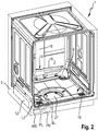
- dishwasher 1 is a household dishwasher and has as part of a body '5 a washing container 2 for receiving items to be processed such as dishes, pots, cutlery, glasses, cooking utensils and. on.
- the items to be washed can be held, for example, in crockery baskets 11 and / or in a cutlery drawer 10, and / or in another item to be washed, and can be loaded with wash liquor or wash liquor liquid by one or more spray devices, such as rotatably mounted spray arms.
- the rinsing container 2 can have an at least substantially rectangular plan with a front side V facing the user in the operating position.
- the front side V can form part of a kitchen front from kitchen furniture standing next to one another or, in the case of a standalone device, also without reference to other furniture.
- the rinsing container 2 can be closed in particular on this front side V by a door 3.
- This door 3 is in Figure 1 shown in a partially open position and then at an angle to the vertical. In its closed position, on the other hand, it stands upright and, according to the drawing, can be swiveled forward and downward in the direction of arrow 4 about its opening about a lower horizontal axis, so that it lies at least almost horizontally in the fully open position.
- the door 3 On its outer and front side V, which is vertical in the closed position and faces the user, the door 3 can be provided with a decorative plate 6 in order to experience an optical and / or haptic upgrade and / or an adaptation to surrounding kitchen furniture.
- the dishwasher 1 is designed here as a stand-alone device or as a so-called partially integrated or also as a fully integrated device.
- the body 5 can also essentially end with the outer walls of the washing compartment 2.
- a housing surrounding this outside can then be partially or completely unnecessary.
- the movable door 3 is assigned in its upper region an operating panel 8 which extends in the transverse direction Q and which can comprise an engagement opening 7 accessible from the front for manual opening and / or closing of the door 3.
- the dishwasher 1 has at least one blow-out opening 9 opening into the washing container 2, via which air can be introduced into the washing container 2 during at least one phase within a program sequence.
- Other numbers of blow-out openings 9 may also be possible.
- the dishwasher 1 is provided with a sorption drying device 12, which is shown in FIG Figure 2 dash-dotted and only schematically drawn. This contains in phases in a sorption container water-absorbing (adsorbing) agent, in particular based on zeolite.
- At least one blower - not shown - is provided, of which air can be moved through the sorption drying device 12, but at least in the direction of the blow-out opening 9 .
- a blower would also be provided, which would move air in the direction of the outlet opening 9. Enrichment with outside air may be possible.
- the dishwasher 1 runs through the partial rinse cycles of different program steps during a wash cycle of a dishwasher program to be carried out, u. a. at least one drying phase (several are also possible), in which an air stream 13 is introduced through the blow-out opening 9 for drying the items to be washed in the washware 2.
- adsorption phase of the sorption drying device 12 there is also at least one desorption phase of the water-absorbing adsorbent, in which heating (not shown for the sake of clarity) either heats the adsorption material and passes air through it or through it Sorption drying device is heated air.
- heating either heats the adsorption material and passes air through it or through it Sorption drying device is heated air.
- water that has been stored in and / or on the adsorption material during a preceding drying cycle is expelled from the adsorption material and taken up by the air passed through the adsorption material.
- Warm, water-containing air is therefore introduced into the washing compartment 2 via the at least one blow-out opening 9 in the desorption phase.
- This phase can be directly or in the program sequence well before the drying phase, in which air from the washing container 2 is dried in the sorption drying device 12 by adsorption and then returned to the washing container 2.
- the blow-out opening 9 can be cooled by means of a separate and directed coolant supply.
- Coolability means that cooling does not have to take place during the entire desorption phase, but can.
- the cooling can also be switched on and off in a clocked manner or can only be in operation during part of the desorption phase.
- Water possibly with cleaning or drying agents, is used as the coolant. This is applied in the appropriate phase in order to minimize noise in a jet 14 that is as uniform as possible on the blow-out cap 15, which covers the blow-out opening 9.
- the water in the dishwasher can be circulated and used several times as a coolant. The consumption is therefore low. In each cycle, thermal energy can be dissipated from the cap 15.
- the coolant can be carried out independently of the wash load with detergent or other washing liquor, i. that is, even if coolant is passed onto the cap 15, no further moisture has to be introduced into the washing container 2, in particular there has to be no action on the items to be washed.
- the coolant supply as a water-carrying channel can have its own separate pipe system 16, which is at least partially independent of an application system for the items to be washed.
- This channel is directed only onto the inflation cover 15 and, in contrast to the rotating nozzles, produces the spray arms make no big noise.
- a spray arm 17 therefore does not have to be used for cooling.
- the own pipe system 16 branches off from a loading system for the items to be washed, namely from a riser pipe 18, which can, for example, supply an upper rotating spray arm with water.
- the water jet 14 used for cooling can be set in a defined manner and acoustically optimized. This active cooling can reduce the overall noise by more than 0.5 dB (A) in the overall level.
- the channel can be created via a separate channel behind a water switch, or a simple coupling can be provided on the riser pipe 18.
- the intervention in the system is limited to a modified feed pipe, which is desirable from a complexity point of view.
- the own pipe system 16 is only exposed to water at a low flow rate, while at a higher flow rate the water runs past branch 19 upwards. This allows the pipe system 16 to be acted upon with a very low output and very low noise level from a water circulating pump.
- This pump can be the same that also supplies the spray arms with rinsing liquor under high load, so that the design effort for the extra cooling is very low.
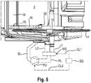
- a circulating pump PU is shown in dash-dot lines as a component of a liquid circulation system which is provided for the loading of washware with washing liquor liquid. It is connected on the inlet side via a suction pipeline SL, which is also shown in dot-dash lines, to the pump pot or liquid collection area 21 of the bottom of the washing container 2, from where it draws in washing liquid which collects during pump operation. On the output side, it is connected to a water diverter WS, also shown in dash-dotted lines, via a pressure pipeline PL, also shown in broken lines.
- a first outlet pipeline L1 leads from the water switch WS to the lower spray arm 17 (see Figure 5 ), a second outlet pipeline L2 to branch 19, which leads via the riser 18 to the upper spray arm and / or another upper spray device such as a roof shower, which here in the Figures 1 - 5 have been omitted for the sake of clarity.
- the Pumping power of the circulation pump PU can be set by means of a control device of the dishwasher 1. This control device is in the Figure 5 additionally indicated by dash-dotted lines and labeled SG.
- the control / regulating device SG can change the positions of the water switch WS with regard to the fluidic coupling of the outlet pipelines L1, L2 to the pressure pipe PL of the circulation pump PU, depending on the desired washing mode in the respective program step of a dishwashing program.
- the outflow pipe line L1 to the lower spray arm 17 can be fluidly connected to the pressure pipe PL of the circulation pump PU by means of a correspondingly selective water switch position.
- only the outlet pipe line L2 to branch 19 can be fluidly connected to the pressure pipe PL of the circulation pump PU by means of a correspondingly selective water switch position.
- so-called interchangeable arm spraying is also possible by continuously changing the water switch position for alternately coupling the pressure pipe PL to the first or second outlet pipeline L1, L2 (in addition to other, further setting options) in the respective program step.
- the WS water switch in the liquid circulation system can also be dispensed with entirely.
- the pressure pipe PL is preferably connected to the two outlet pipes L1, L2 simultaneously via a Y connecting pipe section.
- the own pipe system 16 can run optically inconspicuous, at least in regions, behind a rear wall of the washing compartment 2. Here, laying from the covered riser pipe 18 is shown in the visible area of the washing compartment 2.
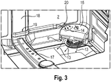
- blow-out opening 9 in a lower corner region of the washing compartment 2 near the rear wall thereof.
- an application end 20 of the pipe system 16 for the application of coolant is directed at the blow-out opening 9, in particular a blow-out cap 15 enclosing this, which is made, for example, of stainless steel.
- the application end 20 of the pipe system 16 for the application of coolant can be narrowed in a nozzle-like manner, as here, for example, in FIG Figure 3 is clearly recognizable.
- the loading end 20 can be aligned such that it is about 1 to 2 cm above the cap 15 at its edge and floods the entire top of the cap 15 with its water jet 14.
- the respective rinse cycle comprises one or more partial rinse cycles or rinse steps such as, for example, a pre-rinse cycle, cleaning cycle, intermediate rinse cycle and rinse cycle, in which each washing or rinsing liquid ("rinsing liquor") is sprayed onto the one or more by means of one or more spray devices in the rinsing container several recordings, in particular crockery baskets, is sprayed.
- a circulation pump is provided, which sucks the washing liquid converging there from a pump pot or liquid collection area in the bottom of the washing container via a suction line and pumps it under pressure into one or more supply pipes into the one or more spray devices. Possibly.
- a partial rinse such as the pre-rinse and / or the intermediate rinse can be omitted.
- a dishwashing program can also be provided, which has only a single wash cycle, such as, for example, only the rinse cycle for loading washware with washing liquid, in particular rinse liquid.
- the last step in the respective rinsing cycle is expediently a drying phase in which moisture from the rinsing container 2 is adsorbed in the sorption drying device 12. It is therefore advantageous if the desorption phase of the water-absorbent agent is within a rinse cycle before a drying phase of the dishes associated with adsorption of the water-absorbent agent. For example, the desorption phase can be directly before drying.
- the dishwasher 1 is therefore also a sterilizer usable. For this, there is also no need to precede a partial rinse with washing liquid, but dishes that have been washed by hand, for example, can only be put into the dishwasher 1 for sterilization and drying.
- a special dishwashing program can expediently be provided, which only carries out the drying cycle and / or the sterilization cycle.
- a UV lamp or an ozone generator can also be provided for sterilization.
- All processes of desorption, adsorption and other phases can be controlled, in particular, via a sequence program, in which, for example, pure sterilization can also be set.
- An optional program design can also be possible, for example in noise-sensitive programs (for example night program) with blow-off cap cooling and in programs which are sensitive to the purge performance, with the cooling of the blow-out cap 15 over the entire spray system.
- noise-sensitive programs for example night program
- programs which are sensitive to the purge performance with the cooling of the blow-out cap 15 over the entire spray system.
- the invention results in an additional noise reduction.
- a very defined loading and cooling of the blow-out cap 15 is possible.
- the cooling cannot be covered by loading the washing compartment 2.
- Retrofitting is possible due to the integration of the pipe system 16 and the small length behind the branch 19. There is no major impact on the rest of the series.
- Figure 6 shows a schematic speed / time diagram for setting the speed of the pump during the course of a rinse cycle SG.
- the rinse cycle SG here includes, for example, the liquid-carrying partial rinse cycles pre-rinse VG, cleaning RG, intermediate rinse ZG and rinse-off KG as well as the final drying cycle TG. It lasts from the start time tA to the end time tE.
- a partial or complete pumping out of the rinsing liquid from the rinsing container is expediently carried out by means of an emptying pump, which is omitted in the figures for the sake of clarity.
- the rinsing liquid is pumped out of the rinsing container as completely as possible.
- washing liquid is sprayed onto the items to be washed by means of the lower and / or upper spraying device.
- the desorption phase KB can preferably be carried out immediately after the end of the spray operation of the rinse aid KG before the drying stage TG.
- the circulation pump PU works with a first set speed n SP during the partial rinse cycles VG, RG, ZG and with a lower second set speed n DE during the desorption phase KB during the rinse cycle KG, which takes place partially or completely during its final section. So there are n SP > n DE .
- the water switch WS is expediently brought into a position by the control device SG via the signal line CL1 such that its outlet pipe L1 is closed to the lower spray arm 17 and only the outlet pipe L2 to the branch 19 is open.
- the speed of the circulation pump is preferably set by the control device SG via the signal line CL2 in such a way that the pump pressure of the circulation pump PU is not sufficient for rinsing liquid to rise above branch 19 into the riser pipe 18 to the upper spray device (s), but instead essentially only flows into the specially provided, separate, in particular here essentially horizontally running, cooling tube 16 and exits from its end opening 20 and flows from there onto the cap 15.
- the outlet end 20 of the cooling tube 16 is preferably somewhat higher than the cap 15, so that the outflowing cooling liquid can flow over it from above. This ensures effective cooling of the cap 15 and thus the blow-out opening 9 during the desorption phase.
- the area around the blow-out opening, in particular the cap 15 above the blow-out opening 9, and thus the air flowing out of the blow-out opening 9 during the desorption phase can be cooled with the rinse aid liquid in a targeted manner via the specially provided pipe system 16.
- the air flowing out of the blow-out opening 9 during the desorption phase preferably only has a temperature of less than 70 ° C. Due to the reduced speed n DE of the circulation pump during the desorption phase KB, in particular the noise of the dishwasher can be reduced during the desorption phase.
- the spray operation takes place in the rinse cycle, for example at a reduced speed n of the circulation pump PU, which essentially corresponds to the speed n DE in the subsequent desorption phase KB (without spray operation).
- a specific “only drying” dishwashing program in which the partial rinse cycles VG, RG, ZG, KG are omitted and only one desorption phase and the subsequent drying cycle TG with the contained adsorption phase are present.
- the outlet opening 9 is expediently cooled by means of the specially provided coolant admission, here through the pipe system 16, as explained above.
- the rinsing tank is expediently given clear fresh water for the desorption phase as a coolant, e.g. fed to the dishwasher via the water supply system.
- no spray operation is expediently carried out by the one or more spray devices present in the washing container.
- the speed of the circulation pump is then preferably selected such that the cooling liquid, here rinse liquid, cannot rise above the branch 19 into the riser 18 to the one or more upper spray devices, but only flows into the cooling pipe 16 and from there onto the Cap 15 flows over the discharge opening 9.
- the cooling liquid here rinse liquid
- the outlet opening can be cooled with the rinse aid liquid from the rinse cycle during the desorption phase before it is finally pumped off before the start of the drying cycle.
Description
Die Erfindung betrifft eine Geschirrspülmaschine, insbesondere eine Haushaltsgeschirrspülmaschine, mit einem Spülbehälter zur Reinigung von Geschirr, Gläsern, Bestecken oder ähnlichem Spülgut und mit einem phasenweise wasseraufnehmenden Mittel einer Sorptionstrocknungseinrichtung, insbesondere auf Basis von Zeolith, wobei während zumindest einer Desorptionsphase des wasseraufnehmenden Mittels erhitzte und wasserhaltige Luft über zumindest eine Ausblasöffnung in den Spülbehälter einleitbar ist, nach dem Oberbegriff des Anspruchs 1.The invention relates to a dishwasher, in particular a domestic dishwasher, with a rinsing container for cleaning dishes, glasses, cutlery or similar items to be washed and with a phase-absorbing agent of a sorption drying device, in particular based on zeolite, with heated and water-containing during at least one desorption phase of the water-absorbing agent Air can be introduced into the washing compartment via at least one blow-out opening, according to the preamble of claim 1.
Bei Sorptionstrocknungseinrichtungen mit einem wasseraufnehmenden Mittel bzw. reversibel dehydriebaren Sorptionsmaterial, wie zum Beispiel Zeolith, sind unterschiedliche Phasen möglich. Während einer Adsorptionsphase wird wasserhaltige Luft aus dem Spülraum durch die Sorptionstrocknungseinrichtung geleitet. Dabei nimmt das Sorptionsmaterial aus der durchströmenden Luft Wasser auf und/oder Wasser haftet an dem Sorptionsmaterial an, um so das Spülgut im Spülbehälter trocknen zu können. In einer Desorptionsphase wird dieses Wasser unter Erhitzung des reversibel dehydrierbaren Sorptionsmittels (mittels einer Heizung) wieder vom Sorptionsmaterial abgegeben und in den Spülbehälter ausgeblasen. Eine solche Desorptionsphase kann beispielsweise vor dem eigentlichen Trocknungsgang des Spülgangs eines Geschirrspülprogramms stattfinden und zeigt den Vorteil, dass am Spülgut verbliebene Reste von Waschmittel, insbesondere Klarspülmittel, durch den entstehenden Wasserdampf verdünnt werden und so eine Fleckenbildung reduziert wird. Nachteilig ist jedoch, dass an der Ausblasöffnung sehr hohe Temperaturen auftreten, etwa über 200°C. Dadurch kann Spülgut im Nahbereich der Ausblasöffnung, insbesondere wenn dieses aus Kunststoff besteht, Schaden nehmen. Gleiches gilt für denjenigen Teil eines Geschirrkorbs oder einer sonstigen Spülgut aufnehmenden Unterbringungseinheit wie z.B. einem Besteckkorb, welcher im Nahbereich der Ausblasöffnung liegt. Zudem können ein oder mehrere Wandflächen des Spülbehälters durch Anströmen mit Luft aus der Ausblasöffnung ggf. so heiß werden, dass deren Berührung für eine Bedienperson unangenehm werden kann, wenn diese während einer Desorptionsphase die Tür der Geschirrspülmaschine öffnet und mit einer Hand in den Spülbehälter hinein an ein derart stark erhitztes Wandteil langt. Es kann schlimmstenfalls sogar Verbrennungs- oder Verbrühgefahr für eine Bedienperson bestehen, etwa wenn von dieser die Tür geöffnet wird, dadurch der Spülgang während einer Desorptionsphase unterbrochen wird, und die Person in den Spülbehälter hineingreift und mit einem zu stark erhitzten Spülgut, zu stark erhitzten Teil eines Geschirrkorbs und/oder einer zu stark erhitzten Wandfläche des Spülbehälters in Kontakt kommt. Eine Kühlung der Ausblasöffnung wird daher angestrebt.Different phases are possible in sorption drying devices with a water-absorbing agent or reversibly dehydrable sorption material, such as, for example, zeolite. During an adsorption phase, water-containing air is passed out of the washing compartment through the sorption drying device. The sorption material absorbs water from the air flowing through and / or water adheres to the sorption material so that the items to be washed can be dried in the washing container. In a desorption phase, this water is released again by the sorption material while the reversibly dehydratable sorbent is heated (by means of a heater) and blown out into the rinsing container. Such a desorption phase can take place, for example, before the actual drying cycle of the dishwashing cycle of a dishwashing program and has the advantage that residues of detergent, in particular rinse aid, remaining on the wash ware are diluted by the water vapor which is formed, and so staining is reduced. However, it is disadvantageous that very high temperatures occur at the blow-out opening, for example above 200 ° C. As a result, items to be washed can be damaged in the vicinity of the blow-out opening, particularly if this is made of plastic. The same applies to that part of a crockery basket or another accommodation unit, such as a cutlery basket, which accommodates items to be washed and which is in the vicinity of the blow-out opening. In addition, one or more wall surfaces of the washing compartment can become so hot, if necessary, that air flows from the blow-out opening so that touching them can be uncomfortable for an operator if the operator opens the door of the dishwasher during a desorption phase and into the washing compartment with one hand such a strongly heated wall part reaches. In the worst case, there may even be a risk of burns or scalding for an operator, for example if the operator opens the door, thereby interrupting the washing cycle during a desorption phase, and the person reaches into the washing container and with too much heated items, too much heated parts a crockery basket and / or an excessively heated wall surface of the washing container comes into contact. Cooling of the blow-out opening is therefore sought.
Z.B. bei der Geschirrspülmaschine der
Der Erfindung liegt das Problem zugrunde, hier eine Verbesserung zu erreichen.The invention is based on the problem of achieving an improvement here.
Die Erfindung löst dieses Problem durch eine Geschirrspülmaschine mit den Merkmalen des Anspruchs 1. Weitere Vorteile und ausgestaltende Merkmale sowie Weiterbildungen der Erfindung sind in den Ansprüchen 2 bis 15 angegeben, deren Merkmale jeweils einzeln oder in Kombination untereinander verwirklicht sein können.The invention solves this problem by a dishwasher with the features of claim 1. Further advantages and design features as well as further developments of the invention are specified in
Dadurch, dass nach Anspruch 1 die Ausblasöffnung über eine eigens vorgesehene, separate, und auf diese gerichtete Kühlmittelbeaufschlagung kühlbar ist, ist es nicht erforderlich, dass eine Kühlung der Ausblasöffnung über eine im Spülbehälter vorhandene Sprüheinrichtung, insbesondere einen rotierenden Sprüharm erfolgt, der zum Besprühen von Spülgut im Spülbehälter vorgesehen ist. Das Versprühen von Flüssigkeit auf das Spülgut durch die Sprüheinrichtung kann also in vorteilhafter Weise eingeschränkt bzw. verringert werden oder ganz unterbleiben. Die Pumpleistung einer Pumpe, insbesondere Umwälzpumpe, die zum Fördern von Waschflüssigkeit bzw. Spülflotte zu ein oder mehreren, im Spülbehälter angeordneten Sprüheinrichtungen vorgesehen ist,_kann dazu während der jeweiligen Desorptionsphase zumindest deutlich vermindert sein, so dass dann entsprechend das Pumpengeräusch der Pumpe verringert ist und somit das Betriebsgeräusch der Geschirrspülmaschine insgesamt betrachtet reduziert ist. Die Absenkung der Pumpleistung lässt sich vorzugsweise durch eine Absenkung der Drehzahl der Pumpe erreichen.Because the blow-out opening can be cooled according to claim 1 by means of a specially provided, separate, and directed towards this coolant, it is not necessary that the blow-out opening is cooled by a spray device in the washing container, in particular a rotating spray arm, which is used for spraying Washware is provided in the wash container. The spraying of liquid onto the items to be washed by the spraying device can thus advantageously be restricted or reduced or avoided entirely. The pumping capacity of a pump, in particular a circulating pump, which is provided for conveying washing liquid or rinsing liquor to one or more spray devices arranged in the rinsing container, can do this be at least significantly reduced during the respective desorption phase, so that the pump noise of the pump is reduced accordingly and thus the operating noise of the dishwasher as a whole is reduced. The pump output can preferably be reduced by reducing the speed of the pump.
Durch die Kühlung der Ausblasöffnung wird die Austrittstemperatur der Luft, die aus der Ausblasöffnung strömt bzw. diese verlässt, gegenüber der Desorptionstemperatur der Luft verringert, die diese ursprünglich nach Durchströmen der das reversibel dehydrierbare Sorptionsmaterial aufweisende Sorptionseinheit der Sorptionstrockeneinrichtung bei der jeweiligen Desorptionsphase hat. Das Desorbieren des reversibel dehydrierbaren Sorptionsmaterials wird zweckmäßigerweise dadurch bewirkt, dass dieses mittels einer der Sorptionseinheit zugeordneten elektrischen Heizung aufgeheizt und von Luft durchströmt wird oder mittels heißer Luft durchströmt wird, die (in Luftströmungsrichtung betrachtet) zuvor mittels einer elektrischen Heizung aufgeheizt worden ist. Die Luft, die die Sorptionseinheit während einer Desorptionsphase verlässt, weist insbesondere eine Desorptionstemperatur zwischen 200° C und 350° C auf und würde ohne Kühlung mit einer Austrittstemperatur von mehr als 100° C aus der Ausblasöffnung in den Innenraum des Spülbehälters ausströmen. Demgegenüber weist jetzt die die Ausblasöffnung verlassende, in den Spülbehälter eintretende Luft durch die Kühlung der Ausblasöffnung mittels der erfindungsgemäßen Vorrichtung zur Kühlmittelbeaufschlagung eine Austrittstemperatur auf, die vorzugsweise kleiner gleich 70° C ist.By cooling the blow-out opening, the outlet temperature of the air which flows out of the blow-out opening is reduced compared to the desorption temperature of the air which it originally had in the respective desorption phase after flowing through the sorption unit of the sorption drying device which has the reversibly dehydratable sorption material. Desorbing the reversibly dehydratable sorption material is expediently brought about by heating it by means of an electrical heater assigned to the sorption unit and flowing air through it or by flowing hot air which (viewed in the direction of air flow) has previously been heated by means of an electrical heater. The air that leaves the sorption unit during a desorption phase has, in particular, a desorption temperature between 200 ° C. and 350 ° C. and would flow out of the outlet opening into the interior of the rinsing container without cooling at an outlet temperature of more than 100 ° C. In contrast, the air leaving the blow-out opening and entering the rinsing container now has an outlet temperature, which is preferably less than or equal to 70 ° C., by cooling the blow-out opening by means of the coolant application device according to the invention.
Vorzugsweise ist als Vorrichtung zur Kühlmittelbeaufschlagung zumindest ein Zuführrohr für Kühlmittel, insbesondere Kühlflüssigkeit, zusätzlich, d.h. eigens zu den ein oder mehreren Sprüheinrichtungen, insbesondere im Spülbetrieb rotierenden Sprüharmen vorgesehen, die der Beaufschlagung von Spülgut mit Spülflüssigkeit bzw. Spülflotte dienen.Preferably, at least one feed pipe for coolant, in particular coolant, is additionally, i.e. Provided specifically for the one or more spray devices, in particular rotating spray arms in the washing mode, which serve to apply wash liquid or wash liquor to washware.
Ggf. kann die Vorrichtung zur Kühlmittelbeaufschlagung auch durch einen drehbar gelagerten Sprüharm gebildet sein, der jedoch für die überwiegende Dauer der Desorptionsphase in eine spezifische stationäre Kühlposition, vorzugsweise Ruhe- bzw. Stillstandsposition, derart gebracht ist, dass ein Flüssigkeits- Sprühstrahl aus mindestens einer Düse des Sprüharms auf die Ausblasöffnung und/oder deren Umgebung für die überwiegende Dauer der Desorptionsphase gerichtet ist. Dieser während der Desorptionsphase in der spezifischen Kühlposition verbleibende, vorzugsweise dort "geparkte" bzw. feststehende, Sprüharm bildet dann ebenfalls eine eigens vorgesehene Vorrichtung zur gezielten Kühlmittelbeaufschlagung der Ausblasöffnung.Possibly. The device for applying coolant can also be formed by a rotatably mounted spray arm, which, however, is brought into a specific stationary cooling position, preferably a rest or standstill position, for the majority of the desorption phase in such a way that a liquid spray jet from at least one nozzle of the spray arm on the discharge opening and / or its surroundings for the predominant duration of the desorption phase is directed. This spray arm, which remains in the specific cooling position during the desorption phase, preferably "parked" or fixed there, then likewise forms a specially provided device for the targeted application of coolant to the blow-out opening.
Zweckmäßigerweise kann die Vorrichtung zur Kühlmittelbeaufschlagung fluidisch mit dem vorhandenen Flüssigkeits- Umwälzkreislauf der Geschirrspülmaschine, der üblicherweise eine Umwälzpumpe, ein oder mehrere im Spülbehälter angeordnete Sprüheinrichtungen sowie zugehörige Flüssigkeitsverbindungsleitungen, und/oder ggf. eine Wasserweiche umfasst, gekoppelt sein. Dann wird die Drehzahl der Umwälzpumpe während der jeweiligen Desorptionsphase vorzugsweise geringer eingestellt als während des Spül- bzw. Sprühbetriebs der Geschirrspülmaschine, bei dem von den ein oder mehreren Sprüheinrichtungen, insbesondere rotierenden Sprüharmen, Spülflüssigkeit auf das zu reinigende Spülgut gesprüht wird. Dies hat den Vorteil, dass durch die während der Desorptionsphase langsamer drehende Pumpe das Geräuschniveau der Geschirrspülmaschine während der Desorptionsphase im Vergleich zum Geräuschniveau beim Spülbetrieb, bei dem die ein oder mehreren Sprüheinrichtungen Spülflüssigkeit mit entsprechend geforderten Sprühdruck auf das Spülgut versprühen, abgesenkt werden kann.The device for the application of coolant can expediently be fluidly coupled to the existing liquid circulation circuit of the dishwasher, which usually comprises a circulation pump, one or more spray devices arranged in the washing container and associated liquid connection lines, and / or possibly a water switch. Then the speed of the circulation pump is preferably set lower during the respective desorption phase than during the washing or spraying operation of the dishwasher, in which washing liquid is sprayed onto the items to be cleaned from the one or more spray devices, in particular rotating spray arms. This has the advantage that the pump, which rotates more slowly during the desorption phase, can lower the noise level of the dishwasher during the desorption phase compared to the noise level during washing operation, in which the one or more spray devices spray washing liquid onto the items to be washed with the required spray pressure.
Verallgemeinert ausgedrückt kann die Drehzahl der Umwälzpumpe insbesondere derart eingestellt werden, dass während der jeweiligen Desorptionsphase von den ein oder mehreren Sprüheinrichtungen im Wesentlichen keine Spülflüssigkeit mehr (wie im Spülbetrieb) auf das Spülgut versprüht wird, sondern nur noch von der Vorrichtung zur Kühlmittelbeaufschlagung allein auf die Ausblasöffnung Kühlmittelflüssigkeit, insbesondere Klarwasser, abgegeben wird.Expressed in general terms, the speed of the circulation pump can in particular be set in such a way that during the respective desorption phase essentially no more rinsing liquid (as in the rinsing mode) is sprayed onto the items to be washed by the one or more spray devices, but only from the device for applying coolant only to the items Blow-out opening coolant liquid, especially clear water, is discharged.
Üblicherweise umfasst ein Spülgang ein oder mehrere Teilspülgänge wie z.B. Vorspülen, Reinigen, Zwischenspülen, Klarspülen, bei dem oder denen jeweils Spülflüssigkeit mittels ein oder mehrere Sprüheinrichtungen auf das zu reinigende Spülgut im Spülbehälter versprüht wird. Die Desorptionsphase kann zweckmäßigerweise während mindestens eines solchen Teilspülgangs erfolgen. Insbesondere ist es energiesparend, wenn die Desorptionsphase zumindest teilweise während eines Teilspülgangs durchgeführt wird, bei der die Aufheizung von Spülflüssigkeit und/oder Spülgut auf eine Mindesttemperatur gefordert ist. Ein solcher Teilspülgang mit aufzuheizender Spülflüssigkeit kann insbesondere der Reinigungsgang und/oder Klarspülgang sein. Die Desorptionsphase kann dabei entweder vollständig während nur eines Teilspülgangs stattfinden oder auch auf mehrere Teilspülgänge zeitlich aufgeteilt sein.Usually, a rinse cycle comprises one or more partial rinse cycles, such as pre-rinsing, cleaning, intermediate rinsing, rinsing, in which washing liquid is sprayed onto the items to be cleaned in the washing container by means of one or more spray devices. The desorption phase can expediently take place during at least one such partial rinse cycle. In particular, it is energy-saving if the desorption phase is carried out at least partially during a partial wash cycle in which the washing-up liquid and / or washware is heated to a minimum temperature is required. Such a partial rinse cycle with rinsing liquid to be heated can in particular be the cleaning cycle and / or rinse cycle. The desorption phase can either take place completely during only one partial rinse cycle or can be divided over several partial rinse cycles.
Vorteilhaft kann es insbesondere sein, wenn die Desorptionsphase zumindest teilweise unmittelbar vor dem spülgangabschließenden Trocknungsgang eines Geschirrspülprogramms erfolgt. Dies hat den Vorteil, das Wasser, das während der Desorptionsphase aus dem Sorptionsmaterial durch dessen Aufheizung ausgetrieben und von der durch das Sorptionsmaterial mittels eines Gebläses zwangsweise hindurchströmenden Luft als Wasserdampf über die Ausblasöffnung in den Spülbehälter befördert wird, sich auch auf dem Spülgut niederschlägt und dort etwaig vorhandene Flüssigkeitsreste, insbesondere Spül- und/oder Klarspülmittelreste, verdünnt, so dass nach dem Trocknungsgang eine für den Benutzer sichtbare Fleckenbildung weitgehend vermieden ist. Außerdem wird das Spülgut durch die beim Desorbieren in den Spülbehälter aus der Ausblasöffnung einströmende heiße Luft aufgeheizt, so dass anschließend im Trocknungsgang zusätzlich zur Sorptionstrocknung eine sogenannte Eigenwärmetrocknung des Spülguts verbessert bewirkt ist. Die Eigenwärmetrocknung beruht dabei auf dem Unterschied zwischen der Temperatur des Spülguts und der Temperatur der Wandungen des Spülbehälters. Je größer der Temperaturunterschied ist und je länger der Temperaturunterschied während des Trocknungsgangs verbleibt, desto besser kommt es zu einer Kondensation von Feuchtigkeit aus der Luft im Spülbehälter an den gegenüber dem Spülgut kühleren Wandungen.It can be particularly advantageous if the desorption phase takes place at least partially immediately before the final drying cycle of a dishwasher program. This has the advantage that the water which is expelled from the sorption material during its desorption phase due to its heating up and is conveyed as water vapor through the blow-out opening into the washing container by the air forcibly flowing through the sorption material, also settles on the items to be washed and there any liquid residues, in particular detergent and / or rinse aid residues, are diluted, so that after the drying cycle, stains visible to the user are largely avoided. In addition, the wash ware is heated by the hot air flowing into the wash container from the blow-out opening during desorbing, so that what is known as self-drying of the wash ware is subsequently improved in addition to sorption drying in the drying cycle. The inherent heat drying is based on the difference between the temperature of the wash items and the temperature of the walls of the wash container. The greater the temperature difference and the longer the temperature difference remains during the drying cycle, the better condensation of moisture from the air in the washing compartment occurs on the walls which are cooler than the items to be washed.
Vor der Abfolge von Trocknungsgang mit unmittelbar vorangestellter Desorptionsphase kann zweckmäßigerweise ein Klarspülgang eines Geschirrspülprogramms durchgeführt werden. Dabei wird die Desorptionsphase in vorteilhafter Weise während des Endabschnitts des Klarspülgangs nach Einstellung des Sprühbetriebs durchgeführt. Die Kühlung der Ausblasöffnung kann dann während der Desorptionsphase mit der Klarspülflüssigkeit aus dem Klarspülgang erfolgen. Dabei kann es nach einer vorteilhaften Ausführungsvariante zweckmäßig sein, wenn - wie in der Desorptionsphase - auch für den der Desorptionsphase vorausgehenden Klarspülgang eine Herabsetzung der Drehzahl der Umwälzpumpe gegenüber einem normalen Klarspülgang (ohne enthaltener Desorptionsphase) vorgenommen wird. Denn so kann Klarspülflüssigkeit mit nur geringem Druck aus den ein oder mehreren Sprüheinrichtungen auf das Spülgut versprüht und somit auf diesem gleichmäßig verteilt werden kann. Es genügt dafür eine geringere Menge an Klarspülflüssigkeit als bei einem Klarspülgang ohne abschließender, dem Trocknungsgang vorangestellter Desorptionsphase. Damit geht ein geringerer thermischer Energieeinsatz zum Aufheizen dieser kleineren Klarspülflüssigkeitsmenge auf eine gewünschte Solltemperatur einher.Before the sequence of drying cycle with immediately preceding desorption phase, a rinse cycle of a dishwasher program can expediently be carried out. The desorption phase is advantageously carried out during the end section of the final rinse cycle after the spray operation has been stopped. The discharge opening can then be cooled with the rinse aid liquid from the rinse cycle during the desorption phase. According to an advantageous embodiment variant, it can be expedient if, as in the desorption phase, the speed of the circulating pump is also reduced for the rinse cycle preceding the desorption phase compared to a normal rinse cycle (without the desorption phase included). Because this is how rinse aid can be used low pressure is sprayed from the one or more spray devices onto the wash ware and can thus be distributed evenly over the wash ware. A smaller amount of rinse aid liquid is sufficient than for a rinse cycle without a final desorption phase preceding the drying cycle. This goes hand in hand with a lower use of thermal energy to heat this smaller amount of rinse liquid to a desired target temperature.
Vorteilhaft kann es sein, wenn die Geschirrspülmaschine ein spezifisches Geschirrspülprogramm bereitstellt, das nur, d.h. ausschließlich, einen Klarspülgang und einen anschließenden Trocknungsgang umfasst, wobei eine Desorptionsphase in vorteilhafter Weise während des Endabschnitts des Klarspülgangs nach Einstellung des vorausgehenden Sprühbetriebs durchgeführt wird. Während dieses Endabschnitts des Klarspülgangs wird dabei die Desorptionsphase, während des Trocknungsgangs die Sorptionsphase der Sorptionstrocknungseinrichtung durchgeführt. Die Kühlung der Ausblasöffnung kann dann während der Desorptionsphase mit der Klarspülflüssigkeit aus dem Klarspülgang erfolgen. Ein solches Spezialprogramm erlaubt es, dass bereits vorgespültes, insbesondere von Hand vorgespültes, Spülgut besonders fleckenfrei getrocknet werden kann. Denn bei der Desorption wird Wasser aus dem Sorptionsmaterial durch dessen Aufheizung ausgetrieben und von der durch das Sorptionsmaterial mittels eines Gebläses zwangsweise hindurchströmenden Luft als Wasserdampf über die Ausblasöffnung in den Spülbehälter befördert, wo er sich auch auf dem Spülgut niederschlägt und dort etwaig vorhandene Spül- und/oder Klarspülmittelreste verdünnt, so dass nach dem Trocknungsgang eine Fleckenbildung weitgehend vermieden ist.It can be advantageous if the dishwasher provides a specific dishwashing program that only, i.e. exclusively comprises a rinse cycle and a subsequent drying cycle, a desorption phase being advantageously carried out during the end section of the rinse cycle after the previous spray operation has been stopped. The desorption phase is carried out during this end section of the rinse cycle, and the sorption phase of the sorption drying device is carried out during the drying cycle. The discharge opening can then be cooled with the rinse aid liquid from the rinse cycle during the desorption phase. Such a special program allows items that have already been rinsed, in particular rinsed by hand, to be dried in a particularly spot-free manner. Because during desorption, water is expelled from the sorption material by heating it up and transported by the air forced through the sorption material by means of a blower as water vapor via the blow-out opening into the washing container, where it is also deposited on the items to be washed and any washing and washing agents present there / or rinse aid residues diluted so that staining is largely avoided after the drying cycle.
Ggf. kann der Klarspülgang auch ganz entfallen. Dann ist dem Trocknungsgang nur noch die Desorptionsphase vorangestellt. Für diesen Fall, wird zweckmäßigerweise Wasser als Kühlmittel dem Spülbehälter eigens zugeführt. Für diese Ausführungsvariante kann eigens ein spezifisches Geschirrspülprogramm "nur Trocknen" bereitgestellt sein.Possibly. the rinse aid cycle can also be omitted entirely. Then only the desorption phase precedes the drying cycle. In this case, water is expediently supplied as a coolant to the washing container. A specific “only drying” dishwashing program can be provided for this embodiment variant.
Wenn die Kühlmittelbeaufschlagung unabhängig von der Spülgutbeaufschlagung durchführbar ist, kann beispielsweise ein Sprüharm in dieser Phase unbeaufschlagt sein und auch selbst nicht zur Geräuschentwicklung beitragen.If the coolant can be applied independently of the items to be washed, a spray arm, for example, can be unloaded in this phase and also not itself contribute to the development of noise.
Insbesondere kann als Kühlmittel Wasser Verwendung finden, so dass eine hohe Kühlleistung und eine gezielte flächendeckende Beaufschlagung der Ausblaskappe möglich sind. Günstig ist dabei das Wasser in der Geschirrspülmaschine umwälzbar und mehrfach als Kühlmittel verwendbar, so dass der Wasserbedarf gering ist und dennoch eine kontinuierliche Wärmeableitung in dieser Phase möglich ist.In particular, water can be used as the coolant, so that a high cooling capacity and a targeted area-wide application of the blow-out cap are possible. The water in the dishwasher can advantageously be circulated and used repeatedly as a coolant, so that the water requirement is low and continuous heat dissipation is nevertheless possible in this phase.
Die Kühlmittelbeaufschlagung kann vorteilhaft ohne gleichzeitige Einleitung von neuer Spülflotte, insbesondere Frischwasser in den Spülbehälter betreibbar sein, um dadurch den Wasserumlauf und auch die benötigte Pumpleistung und Geräuschentwicklung zu minimieren.The application of coolant can advantageously be operated without simultaneous introduction of new washing liquor, in particular fresh water, into the washing container in order to thereby minimize the water circulation and also the required pump power and noise.
Sofern die Kühlmittelbeaufschlagung über ein eigenes Rohrsystem verfügt, ist dieses zumindest teilweise unabhängig von einem Flüssigkeits- Beaufschlagungssystem für das Spülgut.If the coolant supply has its own pipe system, this is at least partially independent of a liquid supply system for the wash ware.
Wenn ein für die Kühlmittelbeaufschlagung eigenes Rohrsystem von einem Beaufschlagungssystem für das Spülgut abzweigt, kann die autarke Kühlung ohne weitere Nutzung des für die Spülgutbeaufschlagung vorgesehenen Rohrsystems konstruktiv einfach realisiert werden. Insbesondere kann der Abzweig des für die Kühlmittelbeaufschlagung vorgesehenen eigenen Rohrsystems vom Spülgut-Beaufschlagungssystem derart ausgebildet sein, dass das für die Kühlmittelbeaufschlagung eigene Rohrsystem nur bei geringer Fließgeschwindigkeit von Wasser beaufschlagt wird, wobei bei höherer Fließgeschwindigkeit das Wasser am Abzweig vorbeiläuft. So kann etwa der Abzweig von einem Steigrohr zum oberen Sprüharm erfolgen. Dann muss dieses für die Kühlung nur bis zum Abzweig mit Wasser beaufschlagt werden, also nur bis in eine Höhe von wenigen Zentimetern, wohingegen zur Beaufschlagung des oberen Sprüharms eine Steighöhe von mehreren zehn Zentimetern erforderlich wäre. Entsprechend kann die Pumpleistung für die Kühlung deutlich reduziert sein.If a pipe system dedicated to the application of coolant branches off from an application system for the items to be washed, self-sufficient cooling can be implemented in a structurally simple manner without further use of the pipe system provided for the items to be washed. In particular, the branch of the own pipe system provided for the coolant supply can be designed from the wash load application system in such a way that the pipe system specific for the coolant supply is only acted upon by water at a low flow rate, the water flowing past the branch at a higher flow rate. For example, the branch from a riser pipe to the upper spray arm can be made. Then this only needs to be acted upon with water for cooling down to the branch, i.e. only up to a height of a few centimeters, whereas a rise of several tens of centimeters would be required to act on the upper spray arm. Accordingly, the pumping power for cooling can be significantly reduced.
Optisch unauffällig kann das eigene Rohrsystem für die Kühlung zumindest bereichsweise hinter einer Rückwand des Spülbehälters verlaufen.Visually inconspicuous, the own pipe system for cooling can run at least in areas behind a rear wall of the washing compartment.
Für einen gerichteten und akustisch in seinem Auftreffwinkel und seiner Intensität optimierten Kühlmittel- Strahl kann das Beaufschlagungsende des Rohrsystems für die Kühlmittelbeaufschlagung düsenartig verengt sein.For a directional coolant jet that is acoustically optimized in terms of its impact angle and its intensity, the application end of the pipe system for the application of coolant can be narrowed like a nozzle.
Besonders günstig liegt die Desorptionsphase des wasseraufnehmenden Mittels innerhalb eines Spülgangs zeitlich vor einer mit einer Adsorption des wasseraufnehmenden Mittels einhergehenden Trocknungsphase des Geschirrs, um als letzte Phase die Trocknung des Spülguts durchführen zu können. Die Abläufe von Desorption, Adsorption und weiteren Phasen können über ein automatisiertes Ablaufprogramm gesteuert sein.The desorption phase of the water-absorbent agent is particularly advantageously within a rinse cycle before a drying phase of the dishes associated with adsorption of the water-absorbent agent, in order to be able to carry out the drying of the washware as the last phase. The processes of desorption, adsorption and other phases can be controlled via an automated process program.
Weiter ist es möglich, dass die Geschirrspülmaschine in Doppelfunktion auch einen Sterilisator für Spülgut ausbildet. Die Sterilisation kann dabei vorzugsweise bereits allein durch die während einer Desorptionsphase aus der Ausblasöffnung ausströmende Luft bewirkt sein. Zusätzlich oder unabhängig hiervon kann für die Sterilisation beispielsweise auch eine zusätzliche UV-Lampe und/oder ein Ozon-Generator vorgesehen sein.It is also possible that the dishwasher also has a double function for sterilizing items to be washed. The sterilization can preferably already be effected solely by the air flowing out of the blow-out opening during a desorption phase. In addition or independently of this, an additional UV lamp and / or an ozone generator can also be provided for the sterilization, for example.
Zusammenfassend betrachtet ist also eine Vorrichtung zur Kühlmittelbeaufschlagung einer ein oder mehrere Ausblasöffnungen aufweisenden Ausblasvorrichtung zusätzlich zu den ein oder mehreren Sprüheinrichtungen im Spülbehälter vorgesehen. Insbesondere kann es vorteilhaft sein, wenn diese Vorrichtung zur Kühlmittelbeaufschlagung feststehend bzw. stationär ausgebildet ist und zumindest einen Wasserstrahl auf die Ausblasvorrichtung während eines Teilabschnitts oder der Gesamtzeitdauer der jeweiligen Desorptionsphase fortlaufend mit derselben Strahlrichtung richtet. Die Strahlrichtung des aus der Vorrichtung zur Kühlmittelbeaufschlagung austretenden Strahls an Kühlflüssigkeit, insbesondere Wasser, bleibt also vorzugsweise dieselbe, d.h. der Kühlflüssigkeitsstrahl ist unbewegt bzw. weitgehend stationär. Dies reduziert das für einen Benutzer wahrnehmbare Betriebsgeräusch der Geschirrspülmaschine im Vergleich zu einem rotierenden Sprüharm, aus dessen Düsen Spülflüssigkeit bzw. Spülflotte während seiner Drehbewegung in viele unterschiedliche Raumrichtungen verspritzt wird und dabei auf verschiedene Flächen und Teile trifft, was ein dynamisches Geräuschbild ergibt.In summary, a device for supplying coolant to a blow-out device having one or more blow-out openings is provided in addition to the one or more spray devices in the washing container. In particular, it can be advantageous if this device for the application of coolant is designed to be stationary or stationary and to direct at least one water jet onto the blow-out device continuously with the same jet direction during a partial section or the total duration of the respective desorption phase. The jet direction of the jet of coolant, in particular water, emerging from the coolant application device therefore preferably remains the same, i.e. the coolant jet is stationary or largely stationary. This reduces the operating noise of the dishwasher that is perceptible to a user in comparison to a rotating spray arm, from the nozzles of which washing liquid or washing liquor is sprayed into many different spatial directions during its rotational movement and thereby hits different surfaces and parts, which results in a dynamic noise pattern.
Sonstige vorteilhafte Weiterbildungen der Erfindung sind in den Unteransprüchen wiedergegeben.Other advantageous developments of the invention are given in the subclaims.
Die vorstehend erläuterten und/oder in den Unteransprüchen wiedergegebenen vorteilhaften Aus- und Weiterbildungen der Erfindung können dabei - außer z. B. in den Fällen eindeutiger Abhängigkeiten oder unvereinbarer Alternativen - einzeln oder aber auch in beliebiger Kombination miteinander zur Anwendung kommen.The above-described and / or reproduced in the dependent claims advantageous refinements and developments of the invention can - except z. B. in the case of clear dependencies or incompatible alternatives - individually or in any combination with each other.
Die Erfindung und ihre vorteilhaften Aus- und Weiterbildungen sowie deren Vorteile werden nachfolgend anhand von Ausführungsbeispiele darstellenden Zeichnungen näher erläutert. Es zeigen, jeweils in einer schematischen Prinzipskizze:
- Fig. 1
- eine schematisch dargestellte Geschirrspülmaschine in perspektivischer Ansicht von schräg vorne bei teilweise geöffneter Tür,
- Fig. 2
- eine schematische Ansicht eines herausgezeichneten Spülbehälters von schräg vorne mit einem in der hinteren rechten Ecke gelegenen Ausblasöffnung für Luft, die die Sorptionstrocknungseinrichtung durchlaufen hat,
- Fig. 3
- eine Detailansicht des Bereichs der von einer Kappe übergriffenen Ausblasöffnung, etwa entsprechend dem Ausschnitt III in
Figur 2 - Fig. 4
- den
Bereich nach Figur 3 in Draufsicht, - Fig. 5
- den
Bereich nach Figur 3 in Ansicht von schräg vorne, und - Fig. 6
- ein schematisches Drehzahl- Zeitdiagramm der Umwälzpumpe der Geschirrspülmaschine der
Figuren 1 - 5 für die Spülbetriebsphase und die Kühlmittelbeaufschlagungsphase während eines durchzuführenden Spülgangs.
- Fig. 1
- 1 shows a schematically illustrated dishwasher in a perspective view obliquely from the front with the door partially open,
- Fig. 2
- 2 shows a schematic view of a flushing container drawn out obliquely from the front with a discharge opening for air located in the rear right corner, which has passed through the sorption drying device,
- Fig. 3
- a detailed view of the area of the discharge opening overlapped by a cap, approximately corresponding to section III in
Figure 2 , - Fig. 4
- the area after
Figure 3 in top view, - Fig. 5
- the area after
Figure 3 in oblique view from the front, and - Fig. 6
- a schematic speed-time diagram of the circulation pump of the dishwasher
Figures 1 - 5 for the flushing operation phase and the coolant loading phase during a flushing cycle to be carried out.
Elemente mit der gleichen Funktion und Wirkungsweise sind in den Figuren jeweils mit den gleichen Bezugszeichen versehen. Dabei sind nur diejenigen Bestandteile einer Geschirrspülmaschine mit Bezugszeichen versehen und erläutert, welche für das Verständnis der Erfindung erforderlich sind.Elements with the same function and mode of operation are provided with the same reference symbols in the figures. Only those components are one Dishwasher provided with reference numerals and explains which are necessary for understanding the invention.
Die in
Der Spülbehälter 2 ist insbesondere an dieser Vorderseite V von einer Tür 3 verschließbar. Diese Tür 3 ist in
An ihrer in Schließstellung vertikalen, dem Benutzer zugewandten Außen- und Vorderseite V kann die Tür 3 mit einer Dekorplatte 6 versehen sein, um damit eine optische und/oder haptische Aufwertung und/oder eine Anpassung an umliegende Küchenmöbel zu erfahren.On its outer and front side V, which is vertical in the closed position and faces the user, the
Der Geschirrspülmaschine 1 ist hier als allein stehendes oder als sog. teilintegriertes oder auch als voll integriertes Gerät ausgebildet. Im letztgenannten Fall kann der Korpus 5 auch im Wesentlichen mit den Außenwandungen des Spülbehälters 2 abschließen. Ein diesen außen umgebendes Gehäuse kann dann teilweise oder ganz entbehrlich sein. Der beweglichen Tür 3 ist im Ausführungsbeispiel gemäß der Zeichnung in ihrem oberen Bereich eine in Querrichtung Q erstreckte Bedienblende 8 zugeordnet, die eine von vorne zugängliche Eingriffsöffnung 7 zum manuellen Öffnen und/oder Schließen der Tür 3 umfassen kann.The dishwasher 1 is designed here as a stand-alone device or as a so-called partially integrated or also as a fully integrated device. In the latter case, the
Weiter verfügt die Geschirrspülmaschine 1 über zumindest eine in den Spülbehälter 2 mündende Ausblasöffnung 9, über die während zumindest einer Phase innerhalb eines Programmablaufs Luft in den Spülbehälter 2 einleitbar ist. Auch andere Anzahlen von Ausblasöffnungen 9 können möglich sein. Hier ragt in
Des Weiteren ist die Geschirrspülmaschine 1 hier mit einer Sorptionstrocknungseinrichtung 12 versehen, die in
Um in dieser Version, aber auch bei einer anderen Ausbildung, das Einblasen von Luft in den Spülbehälter 2 zu ermöglichen, ist zumindest ein Gebläse -nicht gezeichnet - vorgesehen, von dem Luft durch die Sorptionstrocknungseinrichtung 12, zumindest aber in Richtung der Ausblasöffnung 9 bewegbar ist. Beispielsweise bei einer Umlufttrocknung wäre ebenfalls ein solches Gebläse vorgesehen, das Luft in Richtung Ausblasöffnung 9 bewegen würde. Eine Anreicherung mit Außenluft ist dabei ggf. möglich.In order to allow air to be blown into the rinsing
Die Geschirrspülmaschine 1 durchläuft während eines Spülgangs eines durchzuführenden Geschirrspülprogramms die Teilspülgänge unterschiedlicher Programmschritte, u. a. zumindest eine Trocknungsphase (auch mehrere sind möglich), in der ein Luftstrom 13 durch die Ausblasöffnung 9 zur Trocknung des im Spülbehälter 2 befindlichen Spülguts in diesen eingeleitet wird.The dishwasher 1 runs through the partial rinse cycles of different program steps during a wash cycle of a dishwasher program to be carried out, u. a. at least one drying phase (several are also possible), in which an
Neben der o. g. Adsorptionsphase der Sorptionstrocknungseinrichtung 12 gibt es auch zumindest eine Desorptionsphase des wasseraufnehmenden Adsorptionsmittels, in der mittels einer Heizung (der Übersichtlichkeit halber nicht dargestellt) entweder das Adsorptionsmaterial erhitzt und Luft hindurchgeleitet wird, oder die durch die Sorptionstrocknungseinrichtung geleitete Luft erhitzt wird. Auf diese Weise wird Wasser, das im und/oder am Adsorptionsmaterial während eines vorausgehenden Trocknungsgangs gespeichert worden ist, aus dem Adsorptionsmaterial ausgetrieben und von der durch das Adsorptionsmaterial hindurchgeleiteten Luft aufgenommen. Daher wird in der Desorptionsphase warme, wasserhaltige Luft über die zumindest eine Ausblasöffnung 9 in den Spülbehälter 2 eingeleitet. Diese Phase kann direkt oder im Programmablauf weit vor der Trocknungsphase liegen, in der Luft aus dem Spülbehälter 2 in der Sorptionstrocknungseinrichtung 12 durch Adsorption getrocknet und dann wieder in den Spülbehälter 2 rückgeleitet wird.In addition to the above-mentioned adsorption phase of the
Während der Desorptionsphase, in der die Sorptionstrocknungseinrichtung erhitzt ist und entsprechend heiße Luft in den Spülbehälter 2 ausbläst, ist die Ausblasöffnung 9 über eine separate und auf diese gerichtete Kühlmittelbeaufschlagung kühlbar.During the desorption phase, in which the sorption drying device is heated and blows out correspondingly hot air into the rinsing
Die Kühlbarkeit bedeutet, dass nicht während der gesamten Desorptionsphase eine Kühlung stattfinden muss, jedoch kann. Die Kühlung kann auch getaktet ein- und ausgeschaltet werden oder nur während eines Teils der Desorptionsphase in Betrieb sein.Coolability means that cooling does not have to take place during the entire desorption phase, but can. The cooling can also be switched on and off in a clocked manner or can only be in operation during part of the desorption phase.
Als Kühlmittel findet dabei Wasser, eventuell mit Reinigungs- oder Trocknungsmittel versetzt, Verwendung. Dieses wird zur Geräuschminimierung in einem möglichst gleichmäßigen Strahl 14 auf die Ausblaskappe 15, die die Ausblasöffnung 9 überdeckt, in der entsprechenden Phase appliziert. Dabei ist das Wasser in der Geschirrspülmaschine umwälzbar und mehrfach als Kühlmittel verwendbar. Der Verbrauch ist somit gering. In jedem Umlauf kann Wärmeenergie von der Kappe 15 abgeführt werden.Water, possibly with cleaning or drying agents, is used as the coolant. This is applied in the appropriate phase in order to minimize noise in a
Die Kühlmittelbeaufschlagung ist unabhängig von der Spülgutbeaufschlagung mit Reinigungsmittel oder anderer Spülflotte durchführbar, d. h., auch wenn Kühlmittel auf die Kappe 15 geleitet wird, muss keine weitere Feuchtigkeit in den Spülbehälter 2 eingeleitet werden, insbesondere Muss keine Beaufschlagung des Spülguts stattfinden.The coolant can be carried out independently of the wash load with detergent or other washing liquor, i. that is, even if coolant is passed onto the
Wie hier gezeichnet ist, kann die Kühlmittelbeaufschlagung als wasserführenden Kanal über ein eigenes, separates Rohrsystem 16 verfügen, das zumindest teilweise unabhängig von einem Beaufschlagungssystem für das Spülgut ist. Dieser Kanal ist nur auf den Aufblasdeckel 15 gerichtet und erzeugt im Gegensatz zu den rotierenden Düsen der Sprüharme keine großen Geräusche. Ein Sprüharm 17 muss daher nicht zur Kühlung genutzt werden. Das eigene Rohrsystem 16 zweigt hier von einem Beaufschlagungssystem für das Spülgut ab, nämlich von einem Steigrohr 18, das beispielsweise einen oberen rotierbaren Sprüharm mit Wasser versorgen kann. Der zur Kühlung verwendete Wasserstrahl 14 kann definiert eingestellt und akustisch optimiert werden. Durch diese aktive Kühlung kann das Gesamtgeräusch um mehr als 0,5 dB(A) im Gesamtpegel reduziert werden.As shown here, the coolant supply as a water-carrying channel can have its own
Bei der Ausbildung des Rohrsystems 16 sind mehrere Varianten möglich: So kann der Kanal über einen separaten Kanal hinter einer Wasserweiche erzeugt werden, oder es kann eine einfache Kopplung am Steigrohr 18 vorgesehen sein. Mit dieser Möglichkeit ist der Eingriff ins System auf ein modifiziertes Zuführrohr beschränkt, was aus Komplexitätssicht wünschenswert ist.When designing the
Das eigene Rohrsystem 16 wird nur bei geringer Fließgeschwindigkeit von Wasser beaufschlagt wird, während bei höherer Fließgeschwindigkeit das Wasser am Abzweig 19 vorbei nach oben läuft. Damit kann das Rohrsystem 16 bei einer sehr niedrigen Leistung und sehr niedrigen Geräuschentwicklung einer Wasser umwälzenden Pumpe beaufschlagt werden. Diese Pumpe kann dieselbe sein, die bei hoher Last auch die Sprüharme mit Spülflotte versorgt, so dass der konstruktive Aufwand für die Extra-Kühlung sehr gering ist.The
In den
Alternativ kann aber die Wasserweiche WS im Flüssigkeitsumwälzsystem auch ganz entfallen. Dann ist das Druckrohr PL vorzugsweise über einen Y-Verbindungsrohrabschnitt mit den beiden Abgangsrohrleitungen L1, L2 gleichzeitig verbunden.
Das eigene Rohrsystem 16 kann optisch unauffällig zumindest bereichsweise hinter einer Rückwand des Spülbehälters 2 verlaufen. Hier ist eine Verlegung vom verdeckten Steigrohr 18 aus im sichtbaren Bereich des Spülbehälters 2 dargestellt.Alternatively, however, the WS water switch in the liquid circulation system can also be dispensed with entirely. Then the pressure pipe PL is preferably connected to the two outlet pipes L1, L2 simultaneously via a Y connecting pipe section.
The
Weiter ist es insbesondere zur Verringerung der Gefahr von Verbrühungen einer Bedienperson sinnvoll, die Ausblasöffnung 9 in einem unteren Eckbereich des Spülbehälters 2 nahe dessen Rückwand anzuordnen.Furthermore, in order to reduce the risk of scalding for an operator, it is useful to arrange the blow-out
Um es zu ermöglichen, dass der Wasserstrahl 14 die Kappe 15 beaufschlagen kann, ist ein Beaufschlagungsende 20 des Rohrsystems 16 für die Kühlmittelbeaufschlagung auf die Ausblasöffnung 9, insbesondere eine diese einfassende Ausblaskappe 15, die beispielsweise aus Edelstahl besteht, gerichtet. Um den gewünschten Strahl 14 zu bilden, kann das Beaufschlagungsende 20 des Rohrsystems 16 für die Kühlmittelbeaufschlagung düsenartig verengt sein, wie hier beispielsweise in
Üblicherweise umfasst der jeweilige Spülgang ein oder mehrere Teilspülgänge bzw. Spülschritte wie z.B. Vorspülgang, Reinigungsgang, Zwischenspülgang und Klarspülgang, bei dem oder denen jeweils Wasch- bzw. Spülflüssigkeit ("Spülflotte") mittels ein oder mehrerer Sprüheinrichtungen im Spülbehälter auf das in den ein oder mehreren Aufnahmen, insbesondere Geschirrkörben eingelegten Spülgut gesprüht wird. Zur Versorgung dieser Sprüheinrichtungen ist eine Umwälzpumpe vorgesehen, die aus einem Pumpentopf bzw. Flüssigkeitssammelbereich des Bodens des Spülbehälters die dort zusammenlaufende Waschflüssigkeit über eine Saugleitung ansaugt und unter Druck über ein oder mehrere Zuführrohre in die ein oder mehreren Sprüheinrichtungen hineinpumpt. Ggf. kann ein Teilspülgang wie z.B. der Vorspülgang und/oder der Zwischenspülgang entfallen. Insbesondere kann auch ein Geschirrspülprogramm bereitgestellt sein, das lediglich einen einzigen Waschgang wie z.B. nur den Klarspülgang zur Beaufschlagung des Spülguts mit Waschflüssigkeit, insbesondere Klarspülflüssigkeit aufweist. Zweckmäßigerweise ist der letzte Schritt im jeweiligen Spülgang eine Trocknungsphase, in der Feuchtigkeit aus dem Spülbehälter 2 in der Sorptionstrocknungseinrichtung 12 adsorbiert wird. Daher ist es günstig, wenn die Desorptionsphase des wasseraufnehmenden Mittels innerhalb eines Spülgangs zeitlich vor einer mit einer Adsorption des wasseraufnehmenden Mittels einhergehenden Trocknungsphase des Geschirrs gelegen ist. Beispielsweise kann die Desorptionsphase direkt vor der Trocknung liegen. In dem Fall würde der gebildete Wasserdampf gleichzeitig einer Fleckenbildung am Spülgut vorbeugen, indem Reste von Waschflüssigkeit, insbesondere mit Klarspülmittel versetztes Wasser, von dem feuchten Dampf verdünnt werden. Zugleich liefert die heiße, feuchte Luft auch sehr gute Sterilisierungsergebnisse. Die Geschirrspülmaschine 1 ist daher auch als Sterilisator verwendbar. Hierfür muss auch kein Teilspülgang mit Waschflüssigkeit vorausgehen, sondern auch beispielsweise von Hand gespültes Geschirr kann nur zum Sterilisieren und Trocknen in die Geschirrspülmaschine 1 geräumt werden. Es kann dazu zweckmäßigerweise ein spezielles Geschirrspülprogramm bereitgestellt sein, das lediglich den Trocknungsgang und/oder Sterilisationsvorgang durchführt. Zusätzlich kann auch noch eine UV-Lampe oder ein Ozongenerator zum Sterilisieren vorgesehen sein.Usually, the respective rinse cycle comprises one or more partial rinse cycles or rinse steps such as, for example, a pre-rinse cycle, cleaning cycle, intermediate rinse cycle and rinse cycle, in which each washing or rinsing liquid ("rinsing liquor") is sprayed onto the one or more by means of one or more spray devices in the rinsing container several recordings, in particular crockery baskets, is sprayed. To supply these spray devices, a circulation pump is provided, which sucks the washing liquid converging there from a pump pot or liquid collection area in the bottom of the washing container via a suction line and pumps it under pressure into one or more supply pipes into the one or more spray devices. Possibly. a partial rinse such as the pre-rinse and / or the intermediate rinse can be omitted. In particular, a dishwashing program can also be provided, which has only a single wash cycle, such as, for example, only the rinse cycle for loading washware with washing liquid, in particular rinse liquid. The last step in the respective rinsing cycle is expediently a drying phase in which moisture from the rinsing
Sämtliche Abläufe von Desorption, Adsorption und weiteren Phasen sind insbesondere über ein Ablaufprogramm steuerbar, indem beispielsweise auch das reine Sterilisieren einstellbar ist.All processes of desorption, adsorption and other phases can be controlled, in particular, via a sequence program, in which, for example, pure sterilization can also be set.
Es kann auch eine wahlweise Programmgestaltung möglich sein, so zum Beispiel in Geräusch-sensitiven Programmen (zum Beispiel Nachtprogramm) mit Ausblaskappen-Kühlung und in für die reine Spülperformance sensitiven Programmen mit der Kühlung der Ausblaskappe 15 über das gesamte Sprühsystem.An optional program design can also be possible, for example in noise-sensitive programs (for example night program) with blow-off cap cooling and in programs which are sensitive to the purge performance, with the cooling of the blow-out
Insgesamt ergibt sich mit der Erfindung eine zusätzliche Geräuschreduktion. Gleichzeitig ist eine sehr definierte Beaufschlagung und Kühlung der Ausblaskappe 15 möglich. Die Kühlung kann dabei nicht durch Beladung des Spülbehälters 2 verdeckt werden. Durch die Integration des Rohrsystems 16 und die nur kleine Länge hinter dem Abzweig 19 ist eine Nachrüstung möglich. Es sind keine großen Auswirkungen auf die restliche Baureihe nötig.Overall, the invention results in an additional noise reduction. At the same time, a very defined loading and cooling of the blow-out
Wird die Drehzahl der Umwälzpumpe - wie hier im Ausführungsbeispiel von
Insbesondere kann es ggf. zweckmäßig sein, wenn ein spezifisches Geschirrspülprogramm "nur Trocknen" bereitgestellt ist, bei dem die Teilspülgänge VG, RG, ZG, KG entfallen und nur noch eine Desorptionsphase und der daran anschließende Trocknungsgang TG mit enthaltener Adsorptionsphase vorhanden sind. Während der Desorptionsphase erfolgt dabei zweckmäßigerweise die Kühlung der Ausblasöffnung 9 mittels der eigens vorgesehenen, auf diese gerichteten Kühlmittelbeaufschlagung, hier durch das Rohrsystem 16, wie oben erläutert. Für diesen Fall wird dem Spülbehälter zweckmäßigerweise klares Frischwasser für die Desorptionsphase als Kühlmittel wie z.B. über das Wasserzulaufsystem der Geschirrspülmaschine zugeführt. Während der Desorptionsphase wird zweckmäßigerweise kein Sprühbetrieb durch die ein oder mehreren im Spülbehälter vorhandenen Sprüheinrichtungen durchgeführt.In particular, it may be expedient if a specific “only drying” dishwashing program is provided, in which the partial rinse cycles VG, RG, ZG, KG are omitted and only one desorption phase and the subsequent drying cycle TG with the contained adsorption phase are present. During the desorption phase, the
Abweichend zu diesem Geschirrspülprogramm "nur Trocknen" kann es zweckmäßig sein, wenn ein spezifisches Geschirrspülprogramm "Klarspülen und Trocknen" bereitgestellt ist, bei dem die Teilspülgänge VG, RG, ZG entfallen und nur noch ein Klarspülgang KG mit am Ende enthaltener Desorptionsphase und ein daran anschließender Trocknungsgang TG mit enthaltener Adsorptionsphase vorhanden sind. Während der Desorptionsphase wie z.B. KB wird die Wasserweiche WS über die Signalleitung CL1 von der Steuer-/Regelungseinrichtung SG zweckmäßigerweise derart eingestellt, dass das Abgangsrohr L1 zum unteren Sprüharm 17 geschlossen wird und nur das Abgangsrohr L2 zum Abzweig 19 freigegeben wird. Die Drehzahl der Umwälzpumpe ist dann vorzugsweise derart gewählt, dass Kühlflüssigkeit, hier Klarspülflüssigkeit, nicht über die Höhe des Abzweigs 19 hinaus in die Steigleitung 18 zu den ein oder mehreren oberen Sprüheinrichtungen aufsteigen kann, sondern nur in das Kühlrohr 16 strömt und aus diesem auf die Kappe 15 über der Ausblasöffnung 9 fließt. Während der Desorptionsphase wird also kein Sprühbetrieb über die ein oder mehreren Sprüheinrichtungen durchgeführt. Da die Desorptionsphase in vorteilhafter Weise während des Endabschnitts des Klarspülgangs nach Einstellung des vorausgehenden Sprühbetriebs durchgeführt wird, kann die Kühlung der Ausblasöffnung während der Desorptionsphase mit der Klarspülflüssigkeit aus dem Klarspülgang erfolgen, bevor dieses schließlich vor dem Beginn des Trocknungsgangs abgepumpt wird. Ein solches Spezialprogramm erlaubt es, dass bereits vorgespültes, insbesondere von Hand vorgespültes, Spülgut besonders fleckenfrei getrocknet werden kann. Denn bei der Desorption wird Wasser aus dem Sorptionsmaterial durch dessen Aufheizung ausgetrieben und von der durch das Sorptionsmaterial mittels eines Gebläses zwangsweise hindurchströmenden Luft als Wasserdampf über die Ausblasöffnung in den Spülbehälter befördert, wo er sich auch auf dem Spülgut niederschlägt und dort etwaig vorhandene Spül- und/oder Klarspülmittelreste verdünnt, so dass nach dem Trocknungsgang eine Fleckenbildung weitgehend vermieden ist.In a departure from this "only drying" dishwashing program, it may be expedient if a specific "rinse and dry" dishwashing program is provided in which the partial rinse cycles VG, RG, ZG are omitted and only one rinse cycle KG with a desorption phase at the end and a subsequent one Drying cycle TG with contained adsorption phase are present. During the desorption phase, such as KB, the water switch WS is expediently set by the control device SG via the signal line CL1 in such a way that the outlet pipe L1 is closed to the
Die zuvor gemachten Erläuterungen zu vorteilhaften Ausführungsbeispielen der Erfindung nehmen insbesondere Bezug auf folgende Bezugszeichen in den Figuren:
Claims (15)
- Dishwasher (1), in particular household dishwasher, with a dishwasher cavity (2) for cleaning dishware, glasses, cutlery or similar items to be washed and with a means of a sorption drying facility, in particular based on zeolite, which absorbs water in a phased manner, wherein during at least one desorption phase of the water-absorbing means, heated and water-containing air is able to be conducted via at least one exhaust opening (9) into the dishwasher cavity (2), and with one or more spray facilities, in particular spray arms which rotate during washing operating, which are present in the dishwasher cavity (2) and serve to apply wash liquid or wash liquor to items to be washed,
characterised in that
the exhaust opening (9) is able to be cooled via an application of coolant which is specifically provided, separate and aimed at the exhaust opening (9), this being provided additionally to the one or more spray facilities in the dishwasher cavity, or that the exhaust opening (9) is able to be cooled via an application of coolant which is specifically provided and aimed at the exhaust opening (9), this being formed by a rotatably mounted spray arm, said spray arm however being brought into a specific stationary position for most of the duration of the desorption phase, such that a liquid spray jet from at least one nozzle of the spray arm is aimed at the exhaust opening (9) and/or the surrounding area thereof for most of the duration of the desorption phase. - Dishwasher (1) according to claim 1,
characterised in that
the application of coolant is able to be performed independently of the spraying of the items to be washed. - Dishwasher (1) according to claim 2,
characterised in that
water is used as coolant. - Dishwasher (1) according to one of claims 1 to 3,
characterised in that
the water in the dishwasher (1) is able to be recirculated and used as coolant multiple times. - Dishwasher (1) according to one of claims 1 to 4,
characterised in that
the application of coolant is able to be operated without the simultaneous introduction of wash liquor into the dishwasher cavity (2). - Dishwasher (1) according to one of claims 1 to 5,
characterised in that
the application of coolant possesses a specific pipe system (16) which is at least partially independent of a pipe system provided for the spraying of the items to be washed. - Dishwasher (1) according to claim 6,
characterised in that
the specific pipe system (16) branches off from the pipe system provided for the spraying of the items to be washed at a branch (19). - Dishwasher (1) according to claim 7,
characterised in that
water is only applied to the specific pipe system (16) when at low a flow speed; at a higher flow speed the water flows past the branch (19). - Dishwasher (1) according to one of claims 6 to 8,
characterised in that
the specific pipe system (16) runs behind a rear wall of the dishwasher cavity (2), at least in sections. - Dishwasher (1) according to one of claims 1 to 9,
characterised in that
an exhaust opening (9) is situated in a lower corner region of the dishwasher cavity (2), near its rear wall. - Dishwasher (1) according to one of claims 1 to 10,
characterised in that
an application end (20) of the pipe system (16) for the application of coolant is aimed at the exhaust opening (9), in particular an exhaust flap (15) which borders it. - Dishwasher (1) according to claim 11,
characterised in that
the application end (20) of the pipe system (16) for the application of coolant is narrowed in the manner of a nozzle. - Dishwasher (1) according to one of claims 1 to 12,
characterised in that
the desorption phase of the water-absorbing means within a wash cycle takes place in advance of a drying phase of the dishware which accompanies an adsorption of the water-absorption means. - Dishwasher (1) according to one of the preceding claims,
characterised in that
the processes of desorption, adsorption and further phases are controlled via a process program. - Dishwasher (1) according to one of the preceding claims,
characterised in that
said dishwasher also forms a steriliser for items to be washed in a dual function.
Applications Claiming Priority (2)
| Application Number | Priority Date | Filing Date | Title |
|---|---|---|---|
| DE102015212888.1A DE102015212888A1 (en) | 2015-07-09 | 2015-07-09 | Dishwasher with a drying device |
| PCT/EP2016/059868 WO2017005389A1 (en) | 2015-07-09 | 2016-05-03 | Dishwasher having a drying device |
Publications (2)
| Publication Number | Publication Date |
|---|---|
| EP3319501A1 EP3319501A1 (en) | 2018-05-16 |
| EP3319501B1 true EP3319501B1 (en) | 2020-04-15 |
Family
ID=55862805
Family Applications (1)
| Application Number | Title | Priority Date | Filing Date |
|---|---|---|---|
| EP16719881.1A Active EP3319501B1 (en) | 2015-07-09 | 2016-05-03 | Dishwasher having a drying device |
Country Status (3)
| Country | Link |
|---|---|
| EP (1) | EP3319501B1 (en) |
| DE (1) | DE102015212888A1 (en) |
| WO (1) | WO2017005389A1 (en) |
Families Citing this family (2)
| Publication number | Priority date | Publication date | Assignee | Title |
|---|---|---|---|---|
| CN112566938A (en) | 2018-06-03 | 2021-03-26 | 拉姆卡普生物测试有限公司 | Bispecific antibodies against CEACAM5 and CD47 |
| EP3831849A1 (en) | 2019-12-02 | 2021-06-09 | LamKap Bio beta AG | Bispecific antibodies against ceacam5 and cd47 |
Family Cites Families (4)
| Publication number | Priority date | Publication date | Assignee | Title |
|---|---|---|---|---|
| DE10353774A1 (en) * | 2003-07-30 | 2005-02-24 | BSH Bosch und Siemens Hausgeräte GmbH | Drying items in domestic dish washing machines has a reversible hydroscopic material filled column through which recirculated air is driven by a fan |
| DE102008043554A1 (en) | 2008-11-07 | 2010-05-12 | BSH Bosch und Siemens Hausgeräte GmbH | Method for operating dishwasher, particularly domestic dishwasher, involves temporarily treating washing material in inner chamber, and passing fluid air through drying material such as zeolite suitable for exothermic drying |
| DE102008039885A1 (en) * | 2008-08-27 | 2010-04-08 | BSH Bosch und Siemens Hausgeräte GmbH | Dishwasher with Sorptionstrockenvorrichtung |
| DE102013223940B3 (en) * | 2013-11-22 | 2015-04-02 | BSH Bosch und Siemens Hausgeräte GmbH | Dishwasher with sterilization option |
-
2015
- 2015-07-09 DE DE102015212888.1A patent/DE102015212888A1/en not_active Withdrawn
-
2016
- 2016-05-03 EP EP16719881.1A patent/EP3319501B1/en active Active
- 2016-05-03 WO PCT/EP2016/059868 patent/WO2017005389A1/en active Application Filing
Non-Patent Citations (1)
| Title |
|---|
| None * |
Also Published As
| Publication number | Publication date |
|---|---|
| EP3319501A1 (en) | 2018-05-16 |
| WO2017005389A1 (en) | 2017-01-12 |
| DE102015212888A1 (en) | 2017-01-12 |
Similar Documents
| Publication | Publication Date | Title |
|---|---|---|
| DE102015203132B4 (en) | Dishwasher in the form of a commercial utensil or dishwasher designed as a program machine | |
| DE102006025152B4 (en) | Dishwasher and control method for it | |
| DE102006025150B4 (en) | dishwasher | |
| DE102015111994B4 (en) | Dishwasher in the form of a commercial utensil or dishwasher designed as a program machine | |
| WO2010009890A1 (en) | Dishwasher having circulation circuits | |
| DE102010061342A1 (en) | Dishwasher with shared heating | |
| WO2019015964A1 (en) | Dishwasher having one or more loading units | |
| EP2473085B1 (en) | Dishwasher comprising a reservoir and associated preheating method | |
| WO2008113473A1 (en) | Energy-optimized automatic cleaning machine | |
| EP1055389A2 (en) | Programmable dishwasher with device for drying the dishes | |
| DE102008014921A1 (en) | Transport dishwasher and method for operating a conveyor dishwasher | |
| EP2420175A2 (en) | Dishwasher with a manually adjustable rinsing programme | |
| DE102015111883A1 (en) | Dishwasher in the form of a trained as a programmer commercial utensil or dishwasher | |
| DE102014105830A1 (en) | dishwasher | |
| DE102004060947A1 (en) | Household dishwasher and method of operating the same | |
| DE102012207565A1 (en) | Method for operating a dishwasher designed as a programmer and corresponding dishwasher | |
| EP3319501B1 (en) | Dishwasher having a drying device | |
| EP2352411B1 (en) | Method for operating a dishwasher | |
| DE102011083179B4 (en) | Transport dishwasher and method for operating a conveyor dishwasher | |
| EP2326234B1 (en) | Method for operation of a dishwasher | |
| EP2315546B1 (en) | Dishwasher having circulation circuits | |
| DE102018214073B4 (en) | Cleaning device and method for cleaning items to be cleaned | |
| DE102019202152A1 (en) | Rinsing system for cleaning items to be cleaned with at least one cavity | |
| EP2491843B1 (en) | Method for performing a wash programme comprising at least the cleaning, mid-cycle rinse and final rinse program sections | |
| DE102013101673A1 (en) | Dishwasher and method for operating a dishwasher |
Legal Events
| Date | Code | Title | Description |
|---|---|---|---|
| STAA | Information on the status of an ep patent application or granted ep patent |
Free format text: STATUS: THE INTERNATIONAL PUBLICATION HAS BEEN MADE |
|
| PUAI | Public reference made under article 153(3) epc to a published international application that has entered the european phase |
Free format text: ORIGINAL CODE: 0009012 |
|
| STAA | Information on the status of an ep patent application or granted ep patent |
Free format text: STATUS: REQUEST FOR EXAMINATION WAS MADE |
|
| 17P | Request for examination filed |
Effective date: 20180209 |
|
| AK | Designated contracting states |
Kind code of ref document: A1 Designated state(s): AL AT BE BG CH CY CZ DE DK EE ES FI FR GB GR HR HU IE IS IT LI LT LU LV MC MK MT NL NO PL PT RO RS SE SI SK SM TR |
|
| AX | Request for extension of the european patent |
Extension state: BA ME |
|
| DAV | Request for validation of the european patent (deleted) | ||
| DAX | Request for extension of the european patent (deleted) | ||
| STAA | Information on the status of an ep patent application or granted ep patent |
Free format text: STATUS: EXAMINATION IS IN PROGRESS |
|
| 17Q | First examination report despatched |
Effective date: 20190510 |
|
| GRAP | Despatch of communication of intention to grant a patent |
Free format text: ORIGINAL CODE: EPIDOSNIGR1 |
|
| STAA | Information on the status of an ep patent application or granted ep patent |
Free format text: STATUS: GRANT OF PATENT IS INTENDED |
|
| INTG | Intention to grant announced |
Effective date: 20191211 |
|
| GRAS | Grant fee paid |
Free format text: ORIGINAL CODE: EPIDOSNIGR3 |
|
| GRAA | (expected) grant |
Free format text: ORIGINAL CODE: 0009210 |
|
| STAA | Information on the status of an ep patent application or granted ep patent |
Free format text: STATUS: THE PATENT HAS BEEN GRANTED |
|
| AK | Designated contracting states |
Kind code of ref document: B1 Designated state(s): AL AT BE BG CH CY CZ DE DK EE ES FI FR GB GR HR HU IE IS IT LI LT LU LV MC MK MT NL NO PL PT RO RS SE SI SK SM TR |
|
| REG | Reference to a national code |
Ref country code: CH Ref legal event code: EP |
|
| REG | Reference to a national code |
Ref country code: DE Ref legal event code: R096 Ref document number: 502016009549 Country of ref document: DE |
|
| REG | Reference to a national code |
Ref country code: IE Ref legal event code: FG4D Free format text: LANGUAGE OF EP DOCUMENT: GERMAN |
|
| REG | Reference to a national code |
Ref country code: AT Ref legal event code: REF Ref document number: 1256320 Country of ref document: AT Kind code of ref document: T Effective date: 20200515 |
|
| REG | Reference to a national code |
Ref country code: NL Ref legal event code: MP Effective date: 20200415 |
|
| REG | Reference to a national code |
Ref country code: LT Ref legal event code: MG4D |
|
| PG25 | Lapsed in a contracting state [announced via postgrant information from national office to epo] |
Ref country code: LT Free format text: LAPSE BECAUSE OF FAILURE TO SUBMIT A TRANSLATION OF THE DESCRIPTION OR TO PAY THE FEE WITHIN THE PRESCRIBED TIME-LIMIT Effective date: 20200415 Ref country code: NL Free format text: LAPSE BECAUSE OF FAILURE TO SUBMIT A TRANSLATION OF THE DESCRIPTION OR TO PAY THE FEE WITHIN THE PRESCRIBED TIME-LIMIT Effective date: 20200415 Ref country code: NO Free format text: LAPSE BECAUSE OF FAILURE TO SUBMIT A TRANSLATION OF THE DESCRIPTION OR TO PAY THE FEE WITHIN THE PRESCRIBED TIME-LIMIT Effective date: 20200715 Ref country code: PT Free format text: LAPSE BECAUSE OF FAILURE TO SUBMIT A TRANSLATION OF THE DESCRIPTION OR TO PAY THE FEE WITHIN THE PRESCRIBED TIME-LIMIT Effective date: 20200817 Ref country code: SE Free format text: LAPSE BECAUSE OF FAILURE TO SUBMIT A TRANSLATION OF THE DESCRIPTION OR TO PAY THE FEE WITHIN THE PRESCRIBED TIME-LIMIT Effective date: 20200415 Ref country code: GR Free format text: LAPSE BECAUSE OF FAILURE TO SUBMIT A TRANSLATION OF THE DESCRIPTION OR TO PAY THE FEE WITHIN THE PRESCRIBED TIME-LIMIT Effective date: 20200716 Ref country code: IS Free format text: LAPSE BECAUSE OF FAILURE TO SUBMIT A TRANSLATION OF THE DESCRIPTION OR TO PAY THE FEE WITHIN THE PRESCRIBED TIME-LIMIT Effective date: 20200815 Ref country code: FI Free format text: LAPSE BECAUSE OF FAILURE TO SUBMIT A TRANSLATION OF THE DESCRIPTION OR TO PAY THE FEE WITHIN THE PRESCRIBED TIME-LIMIT Effective date: 20200415 |
|
| PG25 | Lapsed in a contracting state [announced via postgrant information from national office to epo] |
Ref country code: RS Free format text: LAPSE BECAUSE OF FAILURE TO SUBMIT A TRANSLATION OF THE DESCRIPTION OR TO PAY THE FEE WITHIN THE PRESCRIBED TIME-LIMIT Effective date: 20200415 Ref country code: HR Free format text: LAPSE BECAUSE OF FAILURE TO SUBMIT A TRANSLATION OF THE DESCRIPTION OR TO PAY THE FEE WITHIN THE PRESCRIBED TIME-LIMIT Effective date: 20200415 Ref country code: LV Free format text: LAPSE BECAUSE OF FAILURE TO SUBMIT A TRANSLATION OF THE DESCRIPTION OR TO PAY THE FEE WITHIN THE PRESCRIBED TIME-LIMIT Effective date: 20200415 Ref country code: BG Free format text: LAPSE BECAUSE OF FAILURE TO SUBMIT A TRANSLATION OF THE DESCRIPTION OR TO PAY THE FEE WITHIN THE PRESCRIBED TIME-LIMIT Effective date: 20200715 |
|
| PG25 | Lapsed in a contracting state [announced via postgrant information from national office to epo] |
Ref country code: AL Free format text: LAPSE BECAUSE OF FAILURE TO SUBMIT A TRANSLATION OF THE DESCRIPTION OR TO PAY THE FEE WITHIN THE PRESCRIBED TIME-LIMIT Effective date: 20200415 |
|
| REG | Reference to a national code |
Ref country code: DE Ref legal event code: R097 Ref document number: 502016009549 Country of ref document: DE |
|
| PG25 | Lapsed in a contracting state [announced via postgrant information from national office to epo] |
Ref country code: CH Free format text: LAPSE BECAUSE OF NON-PAYMENT OF DUE FEES Effective date: 20200531 Ref country code: LI Free format text: LAPSE BECAUSE OF NON-PAYMENT OF DUE FEES Effective date: 20200531 Ref country code: RO Free format text: LAPSE BECAUSE OF FAILURE TO SUBMIT A TRANSLATION OF THE DESCRIPTION OR TO PAY THE FEE WITHIN THE PRESCRIBED TIME-LIMIT Effective date: 20200415 Ref country code: CZ Free format text: LAPSE BECAUSE OF FAILURE TO SUBMIT A TRANSLATION OF THE DESCRIPTION OR TO PAY THE FEE WITHIN THE PRESCRIBED TIME-LIMIT Effective date: 20200415 Ref country code: ES Free format text: LAPSE BECAUSE OF FAILURE TO SUBMIT A TRANSLATION OF THE DESCRIPTION OR TO PAY THE FEE WITHIN THE PRESCRIBED TIME-LIMIT Effective date: 20200415 Ref country code: MC Free format text: LAPSE BECAUSE OF FAILURE TO SUBMIT A TRANSLATION OF THE DESCRIPTION OR TO PAY THE FEE WITHIN THE PRESCRIBED TIME-LIMIT Effective date: 20200415 Ref country code: DK Free format text: LAPSE BECAUSE OF FAILURE TO SUBMIT A TRANSLATION OF THE DESCRIPTION OR TO PAY THE FEE WITHIN THE PRESCRIBED TIME-LIMIT Effective date: 20200415 Ref country code: SM Free format text: LAPSE BECAUSE OF FAILURE TO SUBMIT A TRANSLATION OF THE DESCRIPTION OR TO PAY THE FEE WITHIN THE PRESCRIBED TIME-LIMIT Effective date: 20200415 Ref country code: IT Free format text: LAPSE BECAUSE OF FAILURE TO SUBMIT A TRANSLATION OF THE DESCRIPTION OR TO PAY THE FEE WITHIN THE PRESCRIBED TIME-LIMIT Effective date: 20200415 Ref country code: EE Free format text: LAPSE BECAUSE OF FAILURE TO SUBMIT A TRANSLATION OF THE DESCRIPTION OR TO PAY THE FEE WITHIN THE PRESCRIBED TIME-LIMIT Effective date: 20200415 |
|
| PLBE | No opposition filed within time limit |
Free format text: ORIGINAL CODE: 0009261 |
|
| STAA | Information on the status of an ep patent application or granted ep patent |
Free format text: STATUS: NO OPPOSITION FILED WITHIN TIME LIMIT |
|
| PG25 | Lapsed in a contracting state [announced via postgrant information from national office to epo] |
Ref country code: PL Free format text: LAPSE BECAUSE OF FAILURE TO SUBMIT A TRANSLATION OF THE DESCRIPTION OR TO PAY THE FEE WITHIN THE PRESCRIBED TIME-LIMIT Effective date: 20200415 Ref country code: SK Free format text: LAPSE BECAUSE OF FAILURE TO SUBMIT A TRANSLATION OF THE DESCRIPTION OR TO PAY THE FEE WITHIN THE PRESCRIBED TIME-LIMIT Effective date: 20200415 |
|
| REG | Reference to a national code |
Ref country code: BE Ref legal event code: MM Effective date: 20200531 |
|
| 26N | No opposition filed |
Effective date: 20210118 |
|
| GBPC | Gb: european patent ceased through non-payment of renewal fee |
Effective date: 20200715 |
|
| PG25 | Lapsed in a contracting state [announced via postgrant information from national office to epo] |
Ref country code: LU Free format text: LAPSE BECAUSE OF NON-PAYMENT OF DUE FEES Effective date: 20200503 |
|
| PG25 | Lapsed in a contracting state [announced via postgrant information from national office to epo] |
Ref country code: FR Free format text: LAPSE BECAUSE OF NON-PAYMENT OF DUE FEES Effective date: 20200615 Ref country code: GB Free format text: LAPSE BECAUSE OF NON-PAYMENT OF DUE FEES Effective date: 20200715 Ref country code: IE Free format text: LAPSE BECAUSE OF NON-PAYMENT OF DUE FEES Effective date: 20200503 |
|
| PG25 | Lapsed in a contracting state [announced via postgrant information from national office to epo] |
Ref country code: BE Free format text: LAPSE BECAUSE OF NON-PAYMENT OF DUE FEES Effective date: 20200531 Ref country code: SI Free format text: LAPSE BECAUSE OF FAILURE TO SUBMIT A TRANSLATION OF THE DESCRIPTION OR TO PAY THE FEE WITHIN THE PRESCRIBED TIME-LIMIT Effective date: 20200415 |
|
| PG25 | Lapsed in a contracting state [announced via postgrant information from national office to epo] |
Ref country code: TR Free format text: LAPSE BECAUSE OF FAILURE TO SUBMIT A TRANSLATION OF THE DESCRIPTION OR TO PAY THE FEE WITHIN THE PRESCRIBED TIME-LIMIT Effective date: 20200415 Ref country code: MT Free format text: LAPSE BECAUSE OF FAILURE TO SUBMIT A TRANSLATION OF THE DESCRIPTION OR TO PAY THE FEE WITHIN THE PRESCRIBED TIME-LIMIT Effective date: 20200415 Ref country code: CY Free format text: LAPSE BECAUSE OF FAILURE TO SUBMIT A TRANSLATION OF THE DESCRIPTION OR TO PAY THE FEE WITHIN THE PRESCRIBED TIME-LIMIT Effective date: 20200415 |
|
| PG25 | Lapsed in a contracting state [announced via postgrant information from national office to epo] |
Ref country code: MK Free format text: LAPSE BECAUSE OF FAILURE TO SUBMIT A TRANSLATION OF THE DESCRIPTION OR TO PAY THE FEE WITHIN THE PRESCRIBED TIME-LIMIT Effective date: 20200415 |
|
| REG | Reference to a national code |
Ref country code: AT Ref legal event code: MM01 Ref document number: 1256320 Country of ref document: AT Kind code of ref document: T Effective date: 20210503 |
|
| PG25 | Lapsed in a contracting state [announced via postgrant information from national office to epo] |
Ref country code: AT Free format text: LAPSE BECAUSE OF NON-PAYMENT OF DUE FEES Effective date: 20210503 |
|
| PGFP | Annual fee paid to national office [announced via postgrant information from national office to epo] |
Ref country code: DE Payment date: 20230531 Year of fee payment: 8 |