EP3318933A1 - Vorrichtung zum anhalten und/oder aufziehen eines marinechronometers - Google Patents
Vorrichtung zum anhalten und/oder aufziehen eines marinechronometers Download PDFInfo
- Publication number
- EP3318933A1 EP3318933A1 EP16196926.6A EP16196926A EP3318933A1 EP 3318933 A1 EP3318933 A1 EP 3318933A1 EP 16196926 A EP16196926 A EP 16196926A EP 3318933 A1 EP3318933 A1 EP 3318933A1
- Authority
- EP
- European Patent Office
- Prior art keywords
- cradle
- watch
- winding
- magnetic
- chronometer
- Prior art date
- Legal status (The legal status is an assumption and is not a legal conclusion. Google has not performed a legal analysis and makes no representation as to the accuracy of the status listed.)
- Granted
Links
Images




Classifications
-
- G—PHYSICS
- G04—HOROLOGY
- G04B—MECHANICALLY-DRIVEN CLOCKS OR WATCHES; MECHANICAL PARTS OF CLOCKS OR WATCHES IN GENERAL; TIME PIECES USING THE POSITION OF THE SUN, MOON OR STARS
- G04B37/00—Cases
- G04B37/14—Suspending devices, supports or stands for time-pieces insofar as they form part of the case
- G04B37/1473—Supports and feet for supporting the clockwork
-
- G—PHYSICS
- G04—HOROLOGY
- G04B—MECHANICALLY-DRIVEN CLOCKS OR WATCHES; MECHANICAL PARTS OF CLOCKS OR WATCHES IN GENERAL; TIME PIECES USING THE POSITION OF THE SUN, MOON OR STARS
- G04B37/00—Cases
- G04B37/14—Suspending devices, supports or stands for time-pieces insofar as they form part of the case
- G04B37/1406—Means for fixing the clockwork pieces on other objects (possibly on walls)
- G04B37/1426—Means whereby the clockwork piece may move with regard to its suspension device
-
- G—PHYSICS
- G04—HOROLOGY
- G04B—MECHANICALLY-DRIVEN CLOCKS OR WATCHES; MECHANICAL PARTS OF CLOCKS OR WATCHES IN GENERAL; TIME PIECES USING THE POSITION OF THE SUN, MOON OR STARS
- G04B3/00—Normal winding of clockworks by hand or mechanically; Winding up several mainsprings or driving weights simultaneously
-
- G—PHYSICS
- G04—HOROLOGY
- G04B—MECHANICALLY-DRIVEN CLOCKS OR WATCHES; MECHANICAL PARTS OF CLOCKS OR WATCHES IN GENERAL; TIME PIECES USING THE POSITION OF THE SUN, MOON OR STARS
- G04B3/00—Normal winding of clockworks by hand or mechanically; Winding up several mainsprings or driving weights simultaneously
- G04B3/006—Mechanical winding up; winding up with special equipment
-
- G—PHYSICS
- G04—HOROLOGY
- G04B—MECHANICALLY-DRIVEN CLOCKS OR WATCHES; MECHANICAL PARTS OF CLOCKS OR WATCHES IN GENERAL; TIME PIECES USING THE POSITION OF THE SUN, MOON OR STARS
- G04B3/00—Normal winding of clockworks by hand or mechanically; Winding up several mainsprings or driving weights simultaneously
- G04B3/02—Removably-mounted keys or the like
-
- G—PHYSICS
- G04—HOROLOGY
- G04B—MECHANICALLY-DRIVEN CLOCKS OR WATCHES; MECHANICAL PARTS OF CLOCKS OR WATCHES IN GENERAL; TIME PIECES USING THE POSITION OF THE SUN, MOON OR STARS
- G04B41/00—Locking or holding devices for pendulums, chimes, or the like, for use during transport
-
- G—PHYSICS
- G04—HOROLOGY
- G04B—MECHANICALLY-DRIVEN CLOCKS OR WATCHES; MECHANICAL PARTS OF CLOCKS OR WATCHES IN GENERAL; TIME PIECES USING THE POSITION OF THE SUN, MOON OR STARS
- G04B17/00—Mechanisms for stabilising frequency
- G04B17/20—Compensation of mechanisms for stabilising frequency
- G04B17/28—Compensation of mechanisms for stabilising frequency for the effect of imbalance of the weights, e.g. tourbillon
Definitions
- the invention relates to a marine chronometer, comprising a watch generally large format for keeping time on boats.
- a watch is attached to a support via a cardan suspension so that the watch is tilting in all directions relative to the support.
- the cardan suspension thus ensures the watch and more precisely the dial of the watch a horizontal position regardless of the movements of the boat.
- a cardan suspension is, however, fragile and supports movement, shocks, especially because of the weight of the watch it carries.
- a marine chronometer must be able to be used in difficult climatic conditions and must in particular withstand the water.
- the watch is equipped with a waterproof case.
- the sealing of the mechanical contact zone between the mechanism of the watch, inside the housing, and the winding mechanism, positioned outside the watch case, generally provided by a seal is not always guaranteed regardless of the conditions of use, for example in the case of a time setting the efficiency of the seal can be reduced.
- the invention proposes a new marine chronometer, not exhibiting at least one of the disadvantages of known marine chronometers described above.
- the invention provides a marine chronometer comprising a watch mounted tiltable on a support via a cardan suspension, chronometer characterized in that the support also comprises a cradle movable in translation between a rest position where the watch is free movement on the cardan suspension, and a holding position where the watch is resting on the cradle.
- the cradle in the rest position, supports the weight of the watch, thus unloading the cardan suspension.
- the cradle comprises magnetic means capable of cooperating with associated magnetic means of the watch to immobilize the watch in the cradle when the cradle is in the holding position.
- the cradle may also have an intermediate position between the rest position and the holding position, an intermediate position in which the magnetic means of the cradle are adapted to cooperate with the associated magnetic means of the watch to orient the watch (initially in free rotation on the cardan suspension relative to the cradle, before immobilizing it in the cradle.
- the lifting mechanism is for example manually operated by a lever.
- the watch may comprise a mechanism for winding the barrel of its watch movement and which comprises a winding rotor engaged with a winding train of the conventional mechanical watch movement which will not be described in detail.
- the rotor comprises a plurality of magnetic devices distributed on an outer periphery of the rotor to form the magnetic means of the watch adapted to cooperate with the magnetic means of the cradle when the cradle is in the holding position or in the intermediate position.
- the cradle can in turn comprise an annular stator comprising a plurality of magnetic devices distributed over an inner periphery of the stator to form the magnetic means of the cradle.
- the stator may be a toothed wheel adapted to mesh with a winding pinion arranged outside the watch and independent thereof when the cradle is in the holding position.
- the cradle in the holding position, the cradle can be used on the one hand to immobilize and support the watch, and on the other hand to reassemble the mechanism of the watch.
- the reassembly can be advantageously performed without having to return the housing and thus keeps the reading of the time during the winding operation.
- the winding means comprises an annular stator comprising a plurality of magnetic devices distributed on an inner periphery of the stator, the stator being movable between the winding position and the rest position, the stator being a suitable toothed wheel. to mesh with a winding pinion arranged outside the watch and independent thereof when the stator is in the winding position.
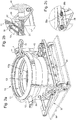
- the invention relates to a marine chronometer comprising a watch 10 mounted tilting on a support 30 via a cardan suspension.
- the watch 10 comprises a housing 11 in the form of a sphere portion in which is housed the clock movement M of the watch, the driving means of which are formed by a barrel B.
- the casing 11 is closed in a sealed manner by an ice under which are positioned the dial C, the hands A, as well as the watch movement as it is visible in the figure 1a .
- the cardan suspension of the watch 10, known per se, is simply represented by a ring 12 of suspension; the mechanical connections between the ring 12 and the support 30 are not shown for the sake of clarity of the figures.
- the chronometer according to the invention is characterized in that the support also comprises a cradle 20 movable in translation between a rest position ( Fig. 1 ) where the watch is free of movement on the cardan suspension, and a holding position ( Fig. 2a , 3 where the watch is resting on the cradle.
- the cradle has an intermediate position between the rest position and the holding position, an intermediate position in which the magnetic means of the cradle are adapted to cooperate with the associated magnetic means of the watch to orient the watch in the cradle.
- the cradle is here movable in translation in a direction substantially perpendicular to the support.
- the lifting mechanism comprises lever 33 and two pairs of rods 34, 35 (cf. Fig. 1 , 2a, 2c in particular), each pair of connecting rods comprising two connecting rods 34, 35 associated in scissors and each pair of connecting rod being coupled to a holding pin 31 in the following manner.
- a pair of connecting rods includes two connecting rods 34, 35 made in the following manner.
- a connecting rod 34 comprises a foot articulated by a pivot connection with the support 30 and a free end of the connecting rod 34 is mechanically articulated with a bracket 31 of the cradle.
- the connecting rod 34 comprises an elastic blade 34b which makes it possible to pinch the lugs of the stator 31a and guarantees a good locking of the housing.
- a connecting rod 35 comprises a foot hinged by a pivot connection with the support 30 and a free end of the connecting rod 35 has an oblong opening 36 extending along a longitudinal axis of the connecting rod 35.
- the two connecting rods 34, 35 are associated together by a pivot link axis 35a passing between the two ends of the connecting rod 24 and between the foot and the oblong opening 36 of the rod 35 to form a scissors effect.
- the free ends of the two rods 35 are rigidly connected together so that the movement of one of the rods 35 mechanically drives an identical movement of the other rod 35.
- the lever 33 has two sides with a substantially L-shape or in "1"; a free end of a large side of the lever forms a grip handle 37; a free end of a small side 38 of the lever is slidably mounted in the oblong opening 36 of the rod 35; two notches 36a, 36b in the oblong opening make it possible to immobilize the free end of the short side of the lever in predefined positions; finally an intersection between the short side and the long side of the lever 33 is articulated with the support 30 by a pivot connection.
- a pair of rods 34, 35 form a closed chisel, the free end of the small side 38 of the lever being positioned in the oblong opening on the side of the axis 35a of the scissors.
- a traction / rotation on the handle 37 of the lever causes a displacement of the free end of the short side 38 of the lever in the oblong opening 36 towards the free end of the rod 35, displacement which in turn causes an elevation of the axis 35a of the scissors and by ricochet an elevation of the free end of the connecting rod 34 and the fixing lug 31a of the cradle along the holding axis 31.
- a traction / rotation of the lever 33 thus causes a translation movement of the cradle 20 along the holding pins.
- the cradle 20 comprises magnetic means 22 capable of cooperating with associated magnetic means 14 of the watch 10 to immobilize the watch in the cradle when the cradle is in the holding position.
- the cradle has in the example shown an annular shape and its magnetic means are distributed on an inner periphery of the cradle.
- the magnetic means 14 of the watch comprise a plurality of magnetic devices distributed around the periphery of the watch case 11, preferably inside the case tight, in a plane substantially parallel to the ice plane of the watch.
- the magnetic coupling between the magnetic means of the cradle and the magnetic means of the watch makes it possible to orient the watch with respect to the cradle to balance the weight of the watch when it rests on the cradle.
- the cradle 20 of the support 30 allows the winding of the watch mechanical clock movement of the watch, in addition to its immobilization.
- the watch 10 comprises a mechanism comprising a winding rotor 13, and the magnetic means 14 comprise a plurality of magnetic devices distributed over an outer periphery of the rotor to form the magnetic means of the watch adapted to cooperate with the magnetic means the cradle when the cradle is in the holding position or in the intermediate position.
- the rotor 13 is associated with a gear 13a coupled in known manner to the usual elements of the winding gears of the barrel.
- the cradle 20 comprises meanwhile an annular stator 21, here in the form of a toothed wheel ( Fig. 3 ) and rotatably mounted relative to the support.
- the stator of the cradle comprises a plurality of magnetic devices 22 distributed over a inner rim of the stator to form the magnetic means of the cradle.
- the cradle also comprises a housing 23 to protect the outer circumference of the stator (toothed wheel).
- magnets permanent or not, or magnetic parts capable of being magnetically coupled to magnets.
- magnets can be used to make the magnetic devices 22 of the cradle and magnetic parts are used to make the magnetic devices 14 of the watch, or vice versa, or magnets are chosen to make the magnetic devices of the cradle. and those of the watch.
- the choice of the magnetic devices, their dimensions, their magnetic force, their number, their distribution on the periphery of the cradle and on the circumference of the watch are chosen according to the magnetic force sought to immobilize the watch on the cradle and / or to drive the winding rotor 13 in rotation.
- the cradle according to the embodiment shown in the figures is used in the following manner.
- the rest position Figs. 5b, 5c
- the cradle rests on the stand and is away from the watch;
- the magnetic means 22 of the cradle and the magnetic means 14 of the watch are spaced from each other so that there is no magnetic coupling between them; the watch is thus free of movement on the cardan suspension.
- the cradle 20 When the user pulls on the handle 37 of the lever 33, the cradle is raised by the mechanism 32 to the intermediate position (corresponding to the notch 36a): the cradle 20 is close to the case 11 of the watch without being in contact and where the magnetic means 22 of the cradle are magnetically coupled with the magnetic means 14 of the watch ( Fig. 5d ).
- the magnetic devices 22 of the stator attract the magnetic devices 14 of the watch until the axis of the stator of the cradle and the axis of the rotor of the watch are aligned, the watch being mounted movably on the cardan suspension . Brought into this position, the watch is kept still and balanced (in terms of weight) above the cradle by magnetic coupling.
- the cradle When the user lowers the lever 33 a little more, the cradle is raised by the mechanism 32 to the holding position (notch 36b): the cradle is in contact with the case 11 of the watch so that the weight of the watch rests on the cradle, the blades 34b contributing to press the stator against the housing 11.
- the magnetic coupling between the magnetic devices 22 of the cradle and the magnetic means 14 of the watch is then maximal.
- the watch is immobilized on the cradle so that the cardan suspension is relieved of the weight of the watch.
- the winding pinion 40 meshes with the stator 21 of the cradle.
- a rotation of the key 41 rotates the winding pinion, which in turn drives the stator 21 in turn.
- the stator rotates the rotor 13 by magnetic coupling, which makes it possible to raise the cylinder of the watch.
- the pallets are supported on the casing 23 of the cradle and are rotated when the cradle 20 is moved in translation.
- a counterweight 52 may be provided on each pallet to hold the pallet in abutment against the casing 23 during movements of the cradle 20.
- the mechanism is of the scissor type, to realize the movement of raising and lowering of the stator but it is understood that according to variants of other types of lifting mechanisms can be envisaged, for example one could provide a mechanism of the knee-type single or two connecting rods or a mechanism of the knee press type or a jack system for example telescopic screw jacks or not.
- Such mechanisms are described in particular in pages 144 and 145 of the book entitled “Elementary Mechanisms" edited by Decoopman, ISBN 97823650027 which are incorporated herein by reference.
Landscapes
- Physics & Mathematics (AREA)
- General Physics & Mathematics (AREA)
- Electric Clocks (AREA)
- Electromechanical Clocks (AREA)
Priority Applications (6)
| Application Number | Priority Date | Filing Date | Title |
|---|---|---|---|
| CH01463/16A CH713106A2 (fr) | 2016-11-02 | 2016-11-02 | Dispositif pour immobiliser et/ou remonter un chronomètre de marine. |
| EP16196926.6A EP3318933B1 (de) | 2016-11-02 | 2016-11-02 | Vorrichtung zum anhalten und/oder aufziehen eines marinechronometers |
| US15/730,900 US10401797B2 (en) | 2016-11-02 | 2017-10-12 | Device for immobilising and/or winding a marine chronometer |
| JP2017204997A JP6483217B2 (ja) | 2016-11-02 | 2017-10-24 | 海洋クロノメータを不動にし、かつ/または巻き上げる装置 |
| CN201711057817.2A CN108021016B (zh) | 2016-11-02 | 2017-11-01 | 用于将航海时计固定不动和/或上条的设备 |
| HK18113084.0A HK1253935B (zh) | 2016-11-02 | 2018-10-12 | 用於将航海时计固定不动和/或上条的设备 |
Applications Claiming Priority (1)
| Application Number | Priority Date | Filing Date | Title |
|---|---|---|---|
| EP16196926.6A EP3318933B1 (de) | 2016-11-02 | 2016-11-02 | Vorrichtung zum anhalten und/oder aufziehen eines marinechronometers |
Publications (2)
| Publication Number | Publication Date |
|---|---|
| EP3318933A1 true EP3318933A1 (de) | 2018-05-09 |
| EP3318933B1 EP3318933B1 (de) | 2020-03-25 |
Family
ID=57223575
Family Applications (1)
| Application Number | Title | Priority Date | Filing Date |
|---|---|---|---|
| EP16196926.6A Active EP3318933B1 (de) | 2016-11-02 | 2016-11-02 | Vorrichtung zum anhalten und/oder aufziehen eines marinechronometers |
Country Status (5)
| Country | Link |
|---|---|
| US (1) | US10401797B2 (de) |
| EP (1) | EP3318933B1 (de) |
| JP (1) | JP6483217B2 (de) |
| CN (1) | CN108021016B (de) |
| CH (1) | CH713106A2 (de) |
Families Citing this family (2)
| Publication number | Priority date | Publication date | Assignee | Title |
|---|---|---|---|---|
| CH714171B1 (fr) * | 2017-09-22 | 2019-08-30 | Montres Breguet Sa | Dispositif pour remonter et/ou immobiliser un chronomètre de marine. |
| USD881058S1 (en) * | 2018-03-05 | 2020-04-14 | Montres Breguet S.A. | Escapement wheel |
Citations (5)
| Publication number | Priority date | Publication date | Assignee | Title |
|---|---|---|---|---|
| US227972A (en) * | 1880-05-25 | oafieis | ||
| CH2960A (fr) * | 1890-12-20 | 1891-04-30 | Nardin Paul D | Perfectionnement apporté à la construction des chronomètres de marine |
| US2425602A (en) * | 1945-01-13 | 1947-08-12 | Hamilton Watch Co | Cantilever support for gimbal carried instruments |
| CH700958A2 (fr) * | 2009-05-06 | 2010-11-15 | Emilia Lacote | Montre a mouvement mobile. |
| CH706352A2 (fr) * | 2012-04-13 | 2013-10-15 | Montres Breguet Sa | Transfert de couple sans contact pour pièce d'horlogerie. |
Family Cites Families (11)
| Publication number | Priority date | Publication date | Assignee | Title |
|---|---|---|---|---|
| US3191901A (en) * | 1962-11-05 | 1965-06-29 | James W Green | Ornamental watch, portrait and plaque stand |
| DE2929372C2 (de) * | 1979-07-20 | 1982-06-09 | Vdo Adolf Schindling Ag, 6000 Frankfurt | Gehäuse für eine Uhr mit einer Halterung |
| USD388001S (en) * | 1995-02-20 | 1997-12-23 | Severin Montres AG (Severin Montres SA) (Severin Montres Ltd) | Watch |
| DE60123403T2 (de) * | 2000-08-11 | 2007-08-23 | Seiko Epson Corp. | Elektronisches gerät und verfahren zu dessen kontrolle |
| CH705244B1 (fr) * | 2011-07-07 | 2016-06-30 | Gfpi S A | Pièce d'horlogerie. |
| EP2560054B1 (de) * | 2011-08-17 | 2017-11-15 | ETA SA Manufacture Horlogère Suisse | Aufzug eines Uhrwerks durch Druck oder Zug |
| EP2787400B1 (de) * | 2013-04-03 | 2016-08-03 | Chopard Technologies SA | Uhrwerk mit Tourbillon und mit Unruhsperrenmechanismus |
| WO2014166719A2 (fr) * | 2013-04-10 | 2014-10-16 | The Swatch Group Research And Development Ltd | Dispositif de remontage de montre à remontage automatique |
| EP2990885B1 (de) * | 2013-12-23 | 2017-07-26 | ETA SA Manufacture Horlogère Suisse | Mechanisches Uhrwerk mit magnetischem Hemmungsmechanismus |
| JP6547379B2 (ja) * | 2015-04-10 | 2019-07-24 | セイコーエプソン株式会社 | 通信システム、電子時計および通信装置 |
| US10324487B2 (en) * | 2016-10-27 | 2019-06-18 | Fluidity Technologies, Inc. | Multi-axis gimbal mounting for controller providing tactile feedback for the null command |
-
2016
- 2016-11-02 EP EP16196926.6A patent/EP3318933B1/de active Active
- 2016-11-02 CH CH01463/16A patent/CH713106A2/fr not_active Application Discontinuation
-
2017
- 2017-10-12 US US15/730,900 patent/US10401797B2/en active Active
- 2017-10-24 JP JP2017204997A patent/JP6483217B2/ja active Active
- 2017-11-01 CN CN201711057817.2A patent/CN108021016B/zh active Active
Patent Citations (5)
| Publication number | Priority date | Publication date | Assignee | Title |
|---|---|---|---|---|
| US227972A (en) * | 1880-05-25 | oafieis | ||
| CH2960A (fr) * | 1890-12-20 | 1891-04-30 | Nardin Paul D | Perfectionnement apporté à la construction des chronomètres de marine |
| US2425602A (en) * | 1945-01-13 | 1947-08-12 | Hamilton Watch Co | Cantilever support for gimbal carried instruments |
| CH700958A2 (fr) * | 2009-05-06 | 2010-11-15 | Emilia Lacote | Montre a mouvement mobile. |
| CH706352A2 (fr) * | 2012-04-13 | 2013-10-15 | Montres Breguet Sa | Transfert de couple sans contact pour pièce d'horlogerie. |
Non-Patent Citations (1)
| Title |
|---|
| "Des Mécanismes Elémentaires", pages: 144,145 |
Also Published As
| Publication number | Publication date |
|---|---|
| CH713106A2 (fr) | 2018-05-15 |
| EP3318933B1 (de) | 2020-03-25 |
| JP2018072338A (ja) | 2018-05-10 |
| HK1253935A1 (zh) | 2019-07-05 |
| US20180120772A1 (en) | 2018-05-03 |
| JP6483217B2 (ja) | 2019-03-13 |
| CN108021016A (zh) | 2018-05-11 |
| CN108021016B (zh) | 2021-01-01 |
| US10401797B2 (en) | 2019-09-03 |
Similar Documents
| Publication | Publication Date | Title |
|---|---|---|
| EP2365407B1 (de) | Vorrichtung zum Aufziehen und zur Zeiteinstellung für ein Uhrwerk | |
| EP1843225A1 (de) | Mechanischer Wechsler zum Drehantreiben eines Rades aus einer einzelnen Richtung | |
| EP2487548B1 (de) | Umkehrmechanismus der Drehbewegung eines Gehäuses | |
| EP2897000B1 (de) | Wendegetriebe für Uhr | |
| FR2688856A1 (fr) | Dispositif de surveillance de la position d'une vanne. | |
| CH709654B1 (fr) | Bascule d'horlogerie et mécanisme de correction rapide comportant une telle bacule. | |
| EP3318933B1 (de) | Vorrichtung zum anhalten und/oder aufziehen eines marinechronometers | |
| BE1000023A7 (fr) | Dispositif de montage d'un accessoire sur un chariot. | |
| EP0401160A1 (de) | Mechanisches Uhrwerk mit Schwungmassen-Selbstaufzug | |
| EP2313812B1 (de) | Uhrwerk mit integrierter automatischer aufzugvorrichtung | |
| CH704783B1 (fr) | Mouvement de pièce d'horlogerie. | |
| EP3333637B1 (de) | Mechanisches uhrwerk mit erfassung der gangreserve | |
| EP3460586B1 (de) | Vorrichtung zum aufziehen und/oder anhalten eines marinechronometers | |
| EP3048043B1 (de) | Vorrichtung zum drehantrieb eines luftfahrzeugrads | |
| EP0008258A1 (de) | Verbesserungen an Tachometern mit Kilometerzähler | |
| EP3881160A1 (de) | Steuerknüppel | |
| WO2011077033A2 (fr) | Dispositif d'obturation et ensemble correspondant | |
| EP1973012B1 (de) | Uhr mit Kinematik zum Ausgleich des Spiels des Aufziehkranzes, der in die Ruhe- oder Aufziehposition versetzt wird | |
| CH715052A2 (fr) | Mécanisme à couple constant, mouvement de pièce d'horlogerie, et pièce d'horlogerie. | |
| EP2761379B1 (de) | Uhrwerk mit tourbillon | |
| CH716476B1 (fr) | Dispositif pour immobiliser un chronomètre de marine. | |
| EP4432018A1 (de) | Uhrwerk, das einen automatischen aufzugsmechanismus umfasst | |
| CH700088A2 (fr) | Différentiel sphérique. | |
| CH343963A (fr) | Mécanisme | |
| EP1582326A1 (de) | Mechanismus für einen Fördertragarm und Tragarmvorrichtung mit solchem Mechanismus |
Legal Events
| Date | Code | Title | Description |
|---|---|---|---|
| PUAI | Public reference made under article 153(3) epc to a published international application that has entered the european phase |
Free format text: ORIGINAL CODE: 0009012 |
|
| STAA | Information on the status of an ep patent application or granted ep patent |
Free format text: STATUS: THE APPLICATION HAS BEEN PUBLISHED |
|
| AK | Designated contracting states |
Kind code of ref document: A1 Designated state(s): AL AT BE BG CH CY CZ DE DK EE ES FI FR GB GR HR HU IE IS IT LI LT LU LV MC MK MT NL NO PL PT RO RS SE SI SK SM TR |
|
| AX | Request for extension of the european patent |
Extension state: BA ME |
|
| STAA | Information on the status of an ep patent application or granted ep patent |
Free format text: STATUS: REQUEST FOR EXAMINATION WAS MADE |
|
| 17P | Request for examination filed |
Effective date: 20181109 |
|
| RBV | Designated contracting states (corrected) |
Designated state(s): AL AT BE BG CH CY CZ DE DK EE ES FI FR GB GR HR HU IE IS IT LI LT LU LV MC MK MT NL NO PL PT RO RS SE SI SK SM TR |
|
| REG | Reference to a national code |
Ref country code: DE Ref legal event code: R079 Ref document number: 602016032432 Country of ref document: DE Free format text: PREVIOUS MAIN CLASS: G04B0041000000 Ipc: G04B0003020000 |
|
| GRAP | Despatch of communication of intention to grant a patent |
Free format text: ORIGINAL CODE: EPIDOSNIGR1 |
|
| RIC1 | Information provided on ipc code assigned before grant |
Ipc: G04B 3/02 20060101AFI20191106BHEP Ipc: G04B 17/28 20060101ALN20191106BHEP Ipc: G04B 37/14 20060101ALI20191106BHEP Ipc: G04B 41/00 20060101ALI20191106BHEP |
|
| STAA | Information on the status of an ep patent application or granted ep patent |
Free format text: STATUS: GRANT OF PATENT IS INTENDED |
|
| RIC1 | Information provided on ipc code assigned before grant |
Ipc: G04B 17/28 20060101ALN20191111BHEP Ipc: G04B 3/02 20060101AFI20191111BHEP Ipc: G04B 37/14 20060101ALI20191111BHEP Ipc: G04B 41/00 20060101ALI20191111BHEP |
|
| INTG | Intention to grant announced |
Effective date: 20191212 |
|
| RIN1 | Information on inventor provided before grant (corrected) |
Inventor name: MACE, JEROME |
|
| GRAS | Grant fee paid |
Free format text: ORIGINAL CODE: EPIDOSNIGR3 |
|
| GRAA | (expected) grant |
Free format text: ORIGINAL CODE: 0009210 |
|
| STAA | Information on the status of an ep patent application or granted ep patent |
Free format text: STATUS: THE PATENT HAS BEEN GRANTED |
|
| AK | Designated contracting states |
Kind code of ref document: B1 Designated state(s): AL AT BE BG CH CY CZ DE DK EE ES FI FR GB GR HR HU IE IS IT LI LT LU LV MC MK MT NL NO PL PT RO RS SE SI SK SM TR |
|
| REG | Reference to a national code |
Ref country code: GB Ref legal event code: FG4D Free format text: NOT ENGLISH |
|
| REG | Reference to a national code |
Ref country code: CH Ref legal event code: NV Representative=s name: ICB INGENIEURS CONSEILS EN BREVETS SA, CH Ref country code: AT Ref legal event code: REF Ref document number: 1249251 Country of ref document: AT Kind code of ref document: T Effective date: 20200415 Ref country code: IE Ref legal event code: FG4D Free format text: LANGUAGE OF EP DOCUMENT: FRENCH |
|
| REG | Reference to a national code |
Ref country code: DE Ref legal event code: R096 Ref document number: 602016032432 Country of ref document: DE |
|
| PG25 | Lapsed in a contracting state [announced via postgrant information from national office to epo] |
Ref country code: NO Free format text: LAPSE BECAUSE OF FAILURE TO SUBMIT A TRANSLATION OF THE DESCRIPTION OR TO PAY THE FEE WITHIN THE PRESCRIBED TIME-LIMIT Effective date: 20200625 Ref country code: RS Free format text: LAPSE BECAUSE OF FAILURE TO SUBMIT A TRANSLATION OF THE DESCRIPTION OR TO PAY THE FEE WITHIN THE PRESCRIBED TIME-LIMIT Effective date: 20200325 Ref country code: FI Free format text: LAPSE BECAUSE OF FAILURE TO SUBMIT A TRANSLATION OF THE DESCRIPTION OR TO PAY THE FEE WITHIN THE PRESCRIBED TIME-LIMIT Effective date: 20200325 |
|
| PG25 | Lapsed in a contracting state [announced via postgrant information from national office to epo] |
Ref country code: BG Free format text: LAPSE BECAUSE OF FAILURE TO SUBMIT A TRANSLATION OF THE DESCRIPTION OR TO PAY THE FEE WITHIN THE PRESCRIBED TIME-LIMIT Effective date: 20200625 Ref country code: GR Free format text: LAPSE BECAUSE OF FAILURE TO SUBMIT A TRANSLATION OF THE DESCRIPTION OR TO PAY THE FEE WITHIN THE PRESCRIBED TIME-LIMIT Effective date: 20200626 Ref country code: LV Free format text: LAPSE BECAUSE OF FAILURE TO SUBMIT A TRANSLATION OF THE DESCRIPTION OR TO PAY THE FEE WITHIN THE PRESCRIBED TIME-LIMIT Effective date: 20200325 Ref country code: SE Free format text: LAPSE BECAUSE OF FAILURE TO SUBMIT A TRANSLATION OF THE DESCRIPTION OR TO PAY THE FEE WITHIN THE PRESCRIBED TIME-LIMIT Effective date: 20200325 Ref country code: HR Free format text: LAPSE BECAUSE OF FAILURE TO SUBMIT A TRANSLATION OF THE DESCRIPTION OR TO PAY THE FEE WITHIN THE PRESCRIBED TIME-LIMIT Effective date: 20200325 |
|
| REG | Reference to a national code |
Ref country code: NL Ref legal event code: MP Effective date: 20200325 |
|
| REG | Reference to a national code |
Ref country code: LT Ref legal event code: MG4D |
|
| PG25 | Lapsed in a contracting state [announced via postgrant information from national office to epo] |
Ref country code: NL Free format text: LAPSE BECAUSE OF FAILURE TO SUBMIT A TRANSLATION OF THE DESCRIPTION OR TO PAY THE FEE WITHIN THE PRESCRIBED TIME-LIMIT Effective date: 20200325 |
|
| PG25 | Lapsed in a contracting state [announced via postgrant information from national office to epo] |
Ref country code: PT Free format text: LAPSE BECAUSE OF FAILURE TO SUBMIT A TRANSLATION OF THE DESCRIPTION OR TO PAY THE FEE WITHIN THE PRESCRIBED TIME-LIMIT Effective date: 20200818 Ref country code: IS Free format text: LAPSE BECAUSE OF FAILURE TO SUBMIT A TRANSLATION OF THE DESCRIPTION OR TO PAY THE FEE WITHIN THE PRESCRIBED TIME-LIMIT Effective date: 20200725 Ref country code: SK Free format text: LAPSE BECAUSE OF FAILURE TO SUBMIT A TRANSLATION OF THE DESCRIPTION OR TO PAY THE FEE WITHIN THE PRESCRIBED TIME-LIMIT Effective date: 20200325 Ref country code: LT Free format text: LAPSE BECAUSE OF FAILURE TO SUBMIT A TRANSLATION OF THE DESCRIPTION OR TO PAY THE FEE WITHIN THE PRESCRIBED TIME-LIMIT Effective date: 20200325 Ref country code: CZ Free format text: LAPSE BECAUSE OF FAILURE TO SUBMIT A TRANSLATION OF THE DESCRIPTION OR TO PAY THE FEE WITHIN THE PRESCRIBED TIME-LIMIT Effective date: 20200325 Ref country code: SM Free format text: LAPSE BECAUSE OF FAILURE TO SUBMIT A TRANSLATION OF THE DESCRIPTION OR TO PAY THE FEE WITHIN THE PRESCRIBED TIME-LIMIT Effective date: 20200325 Ref country code: RO Free format text: LAPSE BECAUSE OF FAILURE TO SUBMIT A TRANSLATION OF THE DESCRIPTION OR TO PAY THE FEE WITHIN THE PRESCRIBED TIME-LIMIT Effective date: 20200325 Ref country code: EE Free format text: LAPSE BECAUSE OF FAILURE TO SUBMIT A TRANSLATION OF THE DESCRIPTION OR TO PAY THE FEE WITHIN THE PRESCRIBED TIME-LIMIT Effective date: 20200325 |
|
| REG | Reference to a national code |
Ref country code: AT Ref legal event code: MK05 Ref document number: 1249251 Country of ref document: AT Kind code of ref document: T Effective date: 20200325 |
|
| REG | Reference to a national code |
Ref country code: DE Ref legal event code: R097 Ref document number: 602016032432 Country of ref document: DE |
|
| PG25 | Lapsed in a contracting state [announced via postgrant information from national office to epo] |
Ref country code: IT Free format text: LAPSE BECAUSE OF FAILURE TO SUBMIT A TRANSLATION OF THE DESCRIPTION OR TO PAY THE FEE WITHIN THE PRESCRIBED TIME-LIMIT Effective date: 20200325 Ref country code: ES Free format text: LAPSE BECAUSE OF FAILURE TO SUBMIT A TRANSLATION OF THE DESCRIPTION OR TO PAY THE FEE WITHIN THE PRESCRIBED TIME-LIMIT Effective date: 20200325 Ref country code: DK Free format text: LAPSE BECAUSE OF FAILURE TO SUBMIT A TRANSLATION OF THE DESCRIPTION OR TO PAY THE FEE WITHIN THE PRESCRIBED TIME-LIMIT Effective date: 20200325 Ref country code: AT Free format text: LAPSE BECAUSE OF FAILURE TO SUBMIT A TRANSLATION OF THE DESCRIPTION OR TO PAY THE FEE WITHIN THE PRESCRIBED TIME-LIMIT Effective date: 20200325 |
|
| PLBE | No opposition filed within time limit |
Free format text: ORIGINAL CODE: 0009261 |
|
| STAA | Information on the status of an ep patent application or granted ep patent |
Free format text: STATUS: NO OPPOSITION FILED WITHIN TIME LIMIT |
|
| PG25 | Lapsed in a contracting state [announced via postgrant information from national office to epo] |
Ref country code: PL Free format text: LAPSE BECAUSE OF FAILURE TO SUBMIT A TRANSLATION OF THE DESCRIPTION OR TO PAY THE FEE WITHIN THE PRESCRIBED TIME-LIMIT Effective date: 20200325 |
|
| 26N | No opposition filed |
Effective date: 20210112 |
|
| PG25 | Lapsed in a contracting state [announced via postgrant information from national office to epo] |
Ref country code: SI Free format text: LAPSE BECAUSE OF FAILURE TO SUBMIT A TRANSLATION OF THE DESCRIPTION OR TO PAY THE FEE WITHIN THE PRESCRIBED TIME-LIMIT Effective date: 20200325 |
|
| PG25 | Lapsed in a contracting state [announced via postgrant information from national office to epo] |
Ref country code: MC Free format text: LAPSE BECAUSE OF FAILURE TO SUBMIT A TRANSLATION OF THE DESCRIPTION OR TO PAY THE FEE WITHIN THE PRESCRIBED TIME-LIMIT Effective date: 20200325 |
|
| PG25 | Lapsed in a contracting state [announced via postgrant information from national office to epo] |
Ref country code: LU Free format text: LAPSE BECAUSE OF NON-PAYMENT OF DUE FEES Effective date: 20201102 |
|
| REG | Reference to a national code |
Ref country code: BE Ref legal event code: MM Effective date: 20201130 |
|
| PG25 | Lapsed in a contracting state [announced via postgrant information from national office to epo] |
Ref country code: IE Free format text: LAPSE BECAUSE OF NON-PAYMENT OF DUE FEES Effective date: 20201102 |
|
| PG25 | Lapsed in a contracting state [announced via postgrant information from national office to epo] |
Ref country code: TR Free format text: LAPSE BECAUSE OF FAILURE TO SUBMIT A TRANSLATION OF THE DESCRIPTION OR TO PAY THE FEE WITHIN THE PRESCRIBED TIME-LIMIT Effective date: 20200325 Ref country code: MT Free format text: LAPSE BECAUSE OF FAILURE TO SUBMIT A TRANSLATION OF THE DESCRIPTION OR TO PAY THE FEE WITHIN THE PRESCRIBED TIME-LIMIT Effective date: 20200325 Ref country code: CY Free format text: LAPSE BECAUSE OF FAILURE TO SUBMIT A TRANSLATION OF THE DESCRIPTION OR TO PAY THE FEE WITHIN THE PRESCRIBED TIME-LIMIT Effective date: 20200325 |
|
| PG25 | Lapsed in a contracting state [announced via postgrant information from national office to epo] |
Ref country code: MK Free format text: LAPSE BECAUSE OF FAILURE TO SUBMIT A TRANSLATION OF THE DESCRIPTION OR TO PAY THE FEE WITHIN THE PRESCRIBED TIME-LIMIT Effective date: 20200325 Ref country code: AL Free format text: LAPSE BECAUSE OF FAILURE TO SUBMIT A TRANSLATION OF THE DESCRIPTION OR TO PAY THE FEE WITHIN THE PRESCRIBED TIME-LIMIT Effective date: 20200325 |
|
| PG25 | Lapsed in a contracting state [announced via postgrant information from national office to epo] |
Ref country code: BE Free format text: LAPSE BECAUSE OF NON-PAYMENT OF DUE FEES Effective date: 20201130 |
|
| P01 | Opt-out of the competence of the unified patent court (upc) registered |
Effective date: 20230611 |
|
| REG | Reference to a national code |
Ref country code: CH Ref legal event code: U11 Free format text: ST27 STATUS EVENT CODE: U-0-0-U10-U11 (AS PROVIDED BY THE NATIONAL OFFICE) Effective date: 20251201 |
|
| PGFP | Annual fee paid to national office [announced via postgrant information from national office to epo] |
Ref country code: DE Payment date: 20251022 Year of fee payment: 10 |
|
| PGFP | Annual fee paid to national office [announced via postgrant information from national office to epo] |
Ref country code: GB Payment date: 20251023 Year of fee payment: 10 |
|
| PGFP | Annual fee paid to national office [announced via postgrant information from national office to epo] |
Ref country code: FR Payment date: 20251022 Year of fee payment: 10 |
|
| PGFP | Annual fee paid to national office [announced via postgrant information from national office to epo] |
Ref country code: CH Payment date: 20251201 Year of fee payment: 10 |