EP3318504A2 - Abdeckkappe mit eingebauter dichtung zur abdichtung einer metallischen flasche - Google Patents
Abdeckkappe mit eingebauter dichtung zur abdichtung einer metallischen flasche Download PDFInfo
- Publication number
- EP3318504A2 EP3318504A2 EP16821701.6A EP16821701A EP3318504A2 EP 3318504 A2 EP3318504 A2 EP 3318504A2 EP 16821701 A EP16821701 A EP 16821701A EP 3318504 A2 EP3318504 A2 EP 3318504A2
- Authority
- EP
- European Patent Office
- Prior art keywords
- cover cap
- metallic
- metallic cover
- flat
- rim
- Prior art date
- Legal status (The legal status is an assumption and is not a legal conclusion. Google has not performed a legal analysis and makes no representation as to the accuracy of the status listed.)
- Granted
Links
Images

Classifications
-
- B—PERFORMING OPERATIONS; TRANSPORTING
- B65—CONVEYING; PACKING; STORING; HANDLING THIN OR FILAMENTARY MATERIAL
- B65D—CONTAINERS FOR STORAGE OR TRANSPORT OF ARTICLES OR MATERIALS, e.g. BAGS, BARRELS, BOTTLES, BOXES, CANS, CARTONS, CRATES, DRUMS, JARS, TANKS, HOPPERS, FORWARDING CONTAINERS; ACCESSORIES, CLOSURES, OR FITTINGS THEREFOR; PACKAGING ELEMENTS; PACKAGES
- B65D41/00—Caps, e.g. crown caps or crown seals, i.e. members having parts arranged for engagement with the external periphery of a neck or wall defining a pouring opening or discharge aperture; Protective cap-like covers for closure members, e.g. decorative covers of metal foil or paper
- B65D41/32—Caps or cap-like covers with lines of weakness, tearing-strips, tags, or like opening or removal devices, e.g. to facilitate formation of pouring openings
- B65D41/325—Caps or cap-like covers with lines of weakness, tearing-strips, tags, or like opening or removal devices, e.g. to facilitate formation of pouring openings with integral internal sealing means
-
- B—PERFORMING OPERATIONS; TRANSPORTING
- B65—CONVEYING; PACKING; STORING; HANDLING THIN OR FILAMENTARY MATERIAL
- B65D—CONTAINERS FOR STORAGE OR TRANSPORT OF ARTICLES OR MATERIALS, e.g. BAGS, BARRELS, BOTTLES, BOXES, CANS, CARTONS, CRATES, DRUMS, JARS, TANKS, HOPPERS, FORWARDING CONTAINERS; ACCESSORIES, CLOSURES, OR FITTINGS THEREFOR; PACKAGING ELEMENTS; PACKAGES
- B65D41/00—Caps, e.g. crown caps or crown seals, i.e. members having parts arranged for engagement with the external periphery of a neck or wall defining a pouring opening or discharge aperture; Protective cap-like covers for closure members, e.g. decorative covers of metal foil or paper
- B65D41/02—Caps or cap-like covers without lines of weakness, tearing strips, tags, or like opening or removal devices
- B65D41/04—Threaded or like caps or cap-like covers secured by rotation
- B65D41/0435—Threaded or like caps or cap-like covers secured by rotation with separate sealing elements
- B65D41/045—Discs
-
- B—PERFORMING OPERATIONS; TRANSPORTING
- B65—CONVEYING; PACKING; STORING; HANDLING THIN OR FILAMENTARY MATERIAL
- B65D—CONTAINERS FOR STORAGE OR TRANSPORT OF ARTICLES OR MATERIALS, e.g. BAGS, BARRELS, BOTTLES, BOXES, CANS, CARTONS, CRATES, DRUMS, JARS, TANKS, HOPPERS, FORWARDING CONTAINERS; ACCESSORIES, CLOSURES, OR FITTINGS THEREFOR; PACKAGING ELEMENTS; PACKAGES
- B65D41/00—Caps, e.g. crown caps or crown seals, i.e. members having parts arranged for engagement with the external periphery of a neck or wall defining a pouring opening or discharge aperture; Protective cap-like covers for closure members, e.g. decorative covers of metal foil or paper
- B65D41/32—Caps or cap-like covers with lines of weakness, tearing-strips, tags, or like opening or removal devices, e.g. to facilitate formation of pouring openings
- B65D41/34—Threaded or like caps or cap-like covers provided with tamper elements formed in, or attached to, the closure skirt
- B65D41/3423—Threaded or like caps or cap-like covers provided with tamper elements formed in, or attached to, the closure skirt with flexible tabs, or elements rotated from a non-engaging to an engaging position, formed on the tamper element or in the closure skirt
- B65D41/3428—Threaded or like caps or cap-like covers provided with tamper elements formed in, or attached to, the closure skirt with flexible tabs, or elements rotated from a non-engaging to an engaging position, formed on the tamper element or in the closure skirt the tamper element being integrally connected to the closure by means of bridges
-
- B—PERFORMING OPERATIONS; TRANSPORTING
- B65—CONVEYING; PACKING; STORING; HANDLING THIN OR FILAMENTARY MATERIAL
- B65D—CONTAINERS FOR STORAGE OR TRANSPORT OF ARTICLES OR MATERIALS, e.g. BAGS, BARRELS, BOTTLES, BOXES, CANS, CARTONS, CRATES, DRUMS, JARS, TANKS, HOPPERS, FORWARDING CONTAINERS; ACCESSORIES, CLOSURES, OR FITTINGS THEREFOR; PACKAGING ELEMENTS; PACKAGES
- B65D41/00—Caps, e.g. crown caps or crown seals, i.e. members having parts arranged for engagement with the external periphery of a neck or wall defining a pouring opening or discharge aperture; Protective cap-like covers for closure members, e.g. decorative covers of metal foil or paper
- B65D41/32—Caps or cap-like covers with lines of weakness, tearing-strips, tags, or like opening or removal devices, e.g. to facilitate formation of pouring openings
- B65D41/34—Threaded or like caps or cap-like covers provided with tamper elements formed in, or attached to, the closure skirt
- B65D41/348—Threaded or like caps or cap-like covers provided with tamper elements formed in, or attached to, the closure skirt the tamper element being rolled or pressed to conform to the shape of the container, e.g. metallic closures
Definitions
- the present invention relates to cover-type metallic caps for sealing bottles; in particular, it refers to a cover cap with fitted gasket designed for sealing a threaded opening of a metallic bottle.
- cover-type metallic caps are formed by a laminated piece with a circular inner- and outer-face layout, from whose edge a peripheral skirt extends in a descending manner and to which a safety ring is attached by a series of bridges, and a gasket attached to the inner face of the circular layout and provided with a flat central zone and an annular zone, including an outer rim and an inner rim separated by a notch.
- These metallic cover caps are used to seal a threaded opening of a glass bottle containing a beverage, whether pressurized or not, since the thread that is formed on the skirt of the cover cap serves to engage with the outer thread of the opening of the glass bottle, while the safety ring attached to the skirt is an indicator of improper tampering with the bottle.
- the skirt and the safety ring are formed by means of a rolling process, in such a way that the skirt acquires a threading that interengages with the outer thread of the opening of the glass bottle, while the safety ring is deformed inwardly by gripping the lower surface of the gripping ring of the opening of the glass bottle, allowing a splice coupling between the sealing surface of the opening of the glass bottle and the gasket.
- the sealing surface of the opening of the glass bottle is housed in the notch of the annular zone of the gasket; at this point, the outer edge of the sealing surface of the opening of the glass bottle engages the inner surface of the outer rim of the annular zone of the gasket, while the inner edge of the sealing surface of the mouth of the glass bottle engages with the inner surface from the inner rim of the annular zone of the gasket, thus ensuring a lateral seal on both sides of the notch, so that the plastic material of the gasket is deformed by the pressure exerted inside the glass bottle.
- the engagement of the notch and of the outer and inner rims over the sealing surface of the mouth of the glass bottle prevents the beverage contained within the glass bottle from escaping.
- the current metallic cover cap that is used to seal the mouth of a glass bottle is not fit for sealing a mouth of a metal bottle, because the mouth of a metallic bottle has a different configuration to the configuration of a mouth of a glass bottle, as observed in Figures 1, 2, and 3 .
- the opening 10 of a glass bottle has a sealing surface 11 with an outer diameter D1 and an inner diameter D2 , an outer thread 12 , and a gripping ring 15.
- the sealing surface 11 has an outer edge 13 and an inner edge 14 where the outer rim and the inner rim of the annular region of the metallic cover cap are respectively seated by the proper obstruction and sealing of the mouth once the metallic cover cap is screwed on.
- the threaded opening 20 of a metallic bottle has a contoured sealing surface 21 with an outer diameter D1 and an inner diameter D2 , an outer thread 22 , and a gripping ring 25 .
- the sealing surface 21 has an outer edge 23 and an inner edge 24 .
- the outer diameter D3 is generally equal to the inner diameter D1 of the sealing surface 11 of the glass bottle 10
- the inner diameter D4 is greater than the outer diameter D2 of the sealing surface 11 of the glass bottle 10.
- the threaded mouth of the glass bottle has a constant diameter and its material has a resistance that does not allow deformation of the mouth during storage, transportation, filling, and sealing of the glass bottle, which favors the proper seating and airtight closing of the metallic crown-type cap.
- the configuration of the mouth of the glass bottle is standardized by the "Glass Packaging Institute.”
- the threaded mouth of the metallic bottle in particular the sealing surface, tends to deform in its own manufacturing process, as well as in the storage, transportation, filling, and sealing of the metallic bottle. This implies that the diameter of the threaded mouth of the metallic bottle has variations or irregularities that can cause a non-airtight closing of the traditional metallic crown-type cap.
- the metallic cover cap currently used to seal glass bottles is not at all suitable for sealing metal bottles, as the current cover cap gasket is not fit to compensate for the variations present in the finish and the diameter of the sealing surface of the threaded mouth of the metal bottle; so, providing a metallic cover cap with a gasket whose design compensates for said imperfections in the threaded mouth of the metal bottle is required.
- the object of the invention is to offer a metallic cover cap for sealing a metallic bottle, the cover cap being formed by a laminated piece with a circular inner- and outer-face layout, from whose edge a peripheral skirt extends in a descending manner and to which a safety ring is attached by a series of bridges, and a gasket attached to the inner face of the circular layout and provided with a flat central zone and an annular zone, including an outer rim and an inner rim separated by a notch, such that the outer rim extends axially and circumferentially continuous and adjacent to the skirt and includes a first flat surface adjacent to the skirt, a second surface with a flat portion and a concave portion facing radially toward the notch, and a third flat surface that extends between the first and second surfaces; the inner rim extends axially and circumferentially continuous and spaced radially inward from the first rim and includes a first flat
- Another object of the present invention is a metallic cover cap in use in combination with a metallic bottle with an opening with an outer thread, a sealing surface and a gripping ring, the cover cap being formed by a laminated piece with a circular inner- and outer-face layout, from whose edge a peripheral skirt extends in a descending manner with an inner thread interengaged to the outer thread of the opening of the metallic bottle, a safety ring attached to the skirt by a series of bridges and grasped to the gripping ring of the opening of the metallic bottle, and a gasket attached to the inner face of the circular layout and coupled to the sealing surface of the opening of the metallic bottle, the gasket being provided with a flat central zone and an annular zone including an outer rim and an inner rim separated by a notch, such that the outer rim extends axially and circumferentially continuous and adjacent to the skirt and includes a first flat surface adjacent to the skirt, a second surface with a flat portion and a concave portion facing radially toward the notch, and
- the present invention relates to a metallic cover cap for sealing a threaded opening of a metallic bottle, this metallic bottle being made of aluminum or any other metal fit for containing a pressurized or unpressurized beverage.
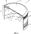
- FIG. 4 shows a longitudinal cross-section view of a metallic cover cap according to the invention.
- the metallic cover cap 30 is shown in its pre-closing condition to seal a threaded opening of a metallic bottle.
- the metallic cover cap 30 is formed by a laminated piece with a circular layout with an outer 40 and an inner face 50 , provided with a peripheral skirt 60 , a safety ring 70 , and a gasket 80.
- the metallic cover cap 30 of the invention is made from metallic sheets, preferably steel or aluminum, having a thickness ranging from approximately 0.160 mm to approximately 0.251 mm.
- the outer face 40 is optionally covered with a pigmented or non-pigmented coating and on which the advertising is printed by means of lithography, for example, the brand of beverage or the bottler.
- the inner face 50 could be covered with a pigmented or non-pigmented coating that could give the metallic cover cap 30 a distinctive character that allows this face to be distinguished and/or be identified at a glance from this perspective versus other metallic cover caps, either during its manufacture, storage, distribution, marketing once such cover has been discarded.
- the peripheral skirt 60 has a knurled band 61 , a labile section 62 , and alternatively a second knurled band (not shown).
- the knurled band 61 allows a better manual grip of the metallic cover cap 30 so that it can be more easily unscrewed from the metallic bottle once in place.
- the labile section 62 is the section that will take a threaded shape by means of a rolling process at the moment when the metallic cover cap 30 is placed on the threaded opening of the metallic bottle.
- a safety ring 70 also known as tamper-proof or tamper-evident ring, is attached to the peripheral skirt 60 by a series of bridges 71 which act as a frangible means.
- the lower edge of the safety ring 70 is collapsible by rolling inwardly to engage and secure the retaining cord of the threaded opening of the metallic bottle once the metallic cover cap 30 is placed over the threaded opening of the metallic bottle, so that when the metallic cover cap 30 is unscrewed from the metallic bottle, then the bridges 71 fracture, causing separation of the safety ring 70 from the skirt 60 , thereby indicating that the metallic bottle has been unduly opened or tampered with.
- the gasket 80 has a circular layout and is positioned on the inner face 50 , either in an adhered manner or formed on the metallic substrate or on the pigmented or non-pigmented coating placed on the inner face 50.
- the gasket 80 is provided with a flat central zone 81 and an annular zone 82 which includes an outer rim 83 and an inner rim 84 separated by a notch 85.
- the notch 85 has a depth of 1.097 mm by 1.562 mm, the flat central zone 81 has a thickness of 0.198 mm to 0.282 mm.
- the gasket 80 is made of a thermoformable material, either PVC, free of PVC, or any other substitute material of PVC and requires a thermoformable material droplet weight of 0.350 grams to 0.440 grams for its elaboration.
- This droplet weight quantity is much lower compared to the droplet weight of thermoformable material required to make the gaskets of the metallic cover caps of the state of the art, hovering around 0.530 grams.
- This smaller quantity of droplet weight makes it possible to obtain a gasket 80 with a lower thickness in the flat central zone 81 and the annular zone 82 , and therefore smaller dimensions in its different elements can be achieved as described below.
- the metallic cover cap 30 of the present invention when being placed in use on a threaded opening of a metallic bottle (see Figure 6 ) is further lowered on the threaded opening to such an extent that the safety ring 70 has a greater contact area with the gripping ring of the threaded opening of the metallic bottle and thus giving rise to a better grip and sealing in comparison with the metallic cover caps of the state of the art.
- the gasket 80 has an inner diameter of approximately 17.5 mm to approximately 18.5 mm measured at the inner edge of the annular zone 82 and an outer diameter of approximately 25 mm to approximately 26.5 mm, measured at the outer edge of the annular zone 82.
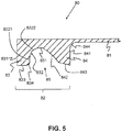
- FIG. 5 a sectional view of one embodiment of the gasket of the metallic cover cap type according to the invention is shown.
- the gasket 80 that is provided with the flat central zone 81 and the annular zone 82 which in turn has the outer rim 83 and the inner rim 84 separated by the notch 85 are adapted to seal the sealing surface of the threaded opening of the metallic bottle.
- the outer rim 83 extends axially and circumferentially continuous and adjacent to the skirt (not shown) and includes a first flat surface 831 adjacent to the skirt (not shown), a second surface 832 with a flat portion 8321 and a concave portion 8322 facing radially toward the notch 85 , and a third flat surface 833 extending between the first flat surface 831 and the second surface 8 32.
- the first flat surface 831 of the outer rim 83 has a height of 1.65 mm to 2.35 mm.
- the concave portion 8322 of the second surface 832 of the outer rim 83 has a radius of 0.589 mm to 0.838 mm.
- the third flat surface 833 measures from 0.80 mm to 1.139 mm.
- the second surface 832 and third flat surface 833 of the outer rim 83 are attached by a convex surface 834 facing radially toward the notch 85.
- the convex surface 834 has a radius of 0.247 mm to 0.352 mm.
- the inner rim 84 extends axially and circumferentially continuous and spaced radially inward from the outer rim 83 and includes a first flat surface 841 facing and perpendicular to the flat central zone 81 , a second concave surface 842 facing radially toward the notch 85 , and a third flat surface 843 inclined toward the notch 85 between the first flat surface 841 and the second concave surface 8 42.
- the inner rim 84 has a base 843 of greater thickness than the thickness of the base 835 of the outer rim 83.
- the base 843 measures from 1.683 mm to 2.397 mm.
- the first flat surface 841 of the inner rim 84 has a height of 1.15 mm to 1.85 mm.
- the second concave surface 842 of the inner rim 84 has a radius of 3.3 mm to 4.7 mm.
- the third flat surface 843 of the inner rim 84 has an angle of inclination of 9.9 degrees to 14.1 degrees and measures from 0.65 mm to 0.95 mm.
- the first flat surface 841 of the inner rim 84 is attached to the flat central zone 81 by a concave surface 844 facing radially toward the flat central zone 81.
- the concave surface 844 has a radius of 1.965 degrees to 2.035 degrees.
- the concave portion 8322 of the second surface 832 of the outer rim 83 is attached to the second concave surface 842 of the inner rim 84 by a flat surface 851 , which represents the deepest part of the notch 85.
- the metallic cover cap can be made in the following stages: first, the laminated piece of circular inner- 40 and outer-face 50 layout can be provided, from whose edge a peripheral skirt 60 extends in a descending manner and to which the safety ring 70 is attached by a series of bridges 71 , and afterwards a droplet of plastic material is molded by in situ pressing on the inner face 40 of the circular layout to configure the gasket 80 provided with the flat central zone 81 and the annular zone 82 , including an outer rim 83 and the inner rim 84 separated by a notch 85 , wherein the outer rim 83 extends axially and circumferentially continuous and adjacent to the peripheral skirt 60 and includes the first flat surface 831 adjacent to the skirt 60 , the second surface 832 with the flat portion 8321 and the concave portion 8322 facing radially toward the notch 85 , and the third flat surface 833 that extends between the first flat surface 831 and the second surface 832 ; the inner rim 84 extends axially and circumfer
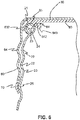
- Figure 6 illustrates a detail view in section of the coupling of a metallic cover cap in use on a threaded opening of a metallic bottle according to the invention.
- the notch 85 of the gasket 80 in particular the second concave surface 842 of the inner rim 84 of the gasket 80 , is seated on the inner edge 24 of the sealing surface 21 of the threaded opening 20 of the metallic bottle, which causes the metallic cover cap 30 to be automatically aligned concentrically to the threaded opening 20 , thus compensating for any irregularity that the threaded opening 20 could have in its circular form.
- This concentric alignment of the metallic cover cap 30 is facilitated by the inclination of the third flat surface 843 and curvature by the second concave surface 842 of the inner rim 84 upon contacting the curvature of the inner edge 24 of the sealing surface 21 of the threaded opening 20 of the metal bottle.
- the peripheral skirt 60 and the safety ring 70 are worked by means of a rolling process, in such a way that the peripheral skirt 60 acquires a thread 64 that is interengaged with the outer thread 22 of the threaded opening 20 of the metallic bottle, while the safety ring 70 deforms inwardly by gripping the lower surface of the gripping ring 25 of the threaded opening 20 of the metallic bottle, which in turn allows a splice coupling between the sealing surface 21 of the threaded opening 20 and the gasket 80 of the metallic cover cap 30 ; in particular, the sealing surface 21 of the threaded opening 20 is housed in the notch 85 of the annular zone 82 of the gasket 80 ; at this point, the outer edge 23 of the sealing surface 21 engages with the second surface 832 of the outer rim 83 of the gasket 80 , while the inner edge 24 of the sealing surface 21 of [sic] engages with the second concave surface 842 of the inner rim
- the outer rim 83 of the gasket 80 undergoes a crush deformation between the outer edge 23 of the sealing surface 21 of the threaded opening 20 of the metallic bottle and the peripheral skirt 60 of the metallic cover cap 30 , thereby allowing a grip between the metallic cover cap 30 and the threaded opening 20 of the metallic bottle; meanwhile, the second rim 24 , because it contains a greater thickness and therefore a higher content of thermoformable material, remains in firm contact with the inner edge 24 of the sealing surface 21 of the threaded opening 20 of the metallic bottle; i.e., the second surface 832 of the outer rim 83 and the second concave surface 842 of the inner rim 84 of the gasket 80 are deformed in such a way that it adopts the curvature of the sealing surface 21 of the threaded opening 20 , even with imperfections in it, thus tightly sealing the threaded opening 20 of the metallic bottle 20.
Landscapes
- Engineering & Computer Science (AREA)
- Mechanical Engineering (AREA)
- Closures For Containers (AREA)
- Gasket Seals (AREA)
Applications Claiming Priority (2)
| Application Number | Priority Date | Filing Date | Title |
|---|---|---|---|
| MX2015008677A MX381077B (es) | 2015-07-03 | 2015-07-03 | Tapa-casquillo con junta adaptada para obturar una botella metálica. |
| PCT/MX2016/000067 WO2017007297A2 (es) | 2015-07-03 | 2016-06-30 | Tapa-casquillo con junta adaptada para obturar una botella metálica |
Publications (4)
| Publication Number | Publication Date |
|---|---|
| EP3318504A2 true EP3318504A2 (de) | 2018-05-09 |
| EP3318504A4 EP3318504A4 (de) | 2019-03-06 |
| EP3318504B1 EP3318504B1 (de) | 2023-11-15 |
| EP3318504C0 EP3318504C0 (de) | 2023-11-15 |
Family
ID=57685941
Family Applications (1)
| Application Number | Title | Priority Date | Filing Date |
|---|---|---|---|
| EP16821701.6A Active EP3318504B1 (de) | 2015-07-03 | 2016-06-30 | Abdeckkappe mit eingebauter dichtung zur abdichtung einer metallischen flasche |
Country Status (11)
| Country | Link |
|---|---|
| US (1) | US10669075B2 (de) |
| EP (1) | EP3318504B1 (de) |
| JP (1) | JP6855474B2 (de) |
| CN (1) | CN108025839B (de) |
| BR (1) | BR112018000117B1 (de) |
| CA (1) | CA2992111C (de) |
| CO (1) | CO2017013478A2 (de) |
| ES (1) | ES2967742T3 (de) |
| MX (1) | MX381077B (de) |
| PL (1) | PL3318504T3 (de) |
| WO (1) | WO2017007297A2 (de) |
Families Citing this family (8)
| Publication number | Priority date | Publication date | Assignee | Title |
|---|---|---|---|---|
| CN110615174B (zh) * | 2018-06-19 | 2022-05-06 | 义乌市易开盖实业公司 | 具有安全提醒结构的包装容器 |
| CN111038837B (zh) * | 2018-10-12 | 2021-09-07 | 义乌市易开盖实业公司 | 适应性强的高密封性扭开盖 |
| JP7203570B2 (ja) * | 2018-10-31 | 2023-01-13 | 大和製罐株式会社 | キャップ |
| GB2579839B (en) * | 2018-12-17 | 2021-09-15 | Crown Packaging Tech | Low migration container |
| USD946405S1 (en) | 2019-03-20 | 2022-03-22 | Ball Corporation | Metal food container |
| USD982458S1 (en) | 2019-10-24 | 2023-04-04 | Ball Corporation | Metal food container |
| US12168551B2 (en) | 2021-03-01 | 2024-12-17 | Ball Corporation | Metal container and end closure with seal |
| US12325559B2 (en) * | 2023-01-03 | 2025-06-10 | Uab Baltic Caps | Closure device |
Family Cites Families (34)
| Publication number | Priority date | Publication date | Assignee | Title |
|---|---|---|---|---|
| US2158683A (en) | 1935-06-17 | 1939-05-16 | White Cap Co | Closure cap |
| GB521860A (en) | 1938-11-28 | 1940-06-03 | Metal Closures Ltd | Improvements in or relating to closures for bottles and like containers |
| GB605292A (en) | 1945-12-19 | 1948-07-20 | Leonard Faviell Gee | Improvements in or relating to the opening of sealed bottles and like containers |
| NL127574C (de) | 1965-01-20 | |||
| GB1226245A (de) | 1968-07-17 | 1971-03-24 | ||
| DE1944346A1 (de) | 1968-09-04 | 1970-03-12 | Armando Podesta | Verfahren und Vorrichtung zur Herstellung von Verschlusskapseln und nach diesem Verfahren hergestellten Verschlusskapseln |
| US3503534A (en) | 1968-11-26 | 1970-03-31 | Continental Can Co | Bottle cap having protective skirt edge |
| FR2230555A2 (en) | 1973-05-25 | 1974-12-20 | Scal Gp Condit Aluminium | Sheet metal screw top for bottle - has tear off strip between locking deformations engaging deformation in bottle |
| US3887100A (en) | 1973-10-25 | 1975-06-03 | Monarch Wine Co Inc | Anti strip overcap for metal screw caps for bottles or containers |
| FR2339540A1 (fr) | 1976-01-28 | 1977-08-26 | Bouchons Plastiques | Perfectionnements aux bouchons a vis |
| GB1552713A (en) | 1976-03-11 | 1979-09-19 | Crown Cork Japan | Cap and sealing method |
| US4165009A (en) * | 1978-01-12 | 1979-08-21 | Japan Crown Cork Co., Ltd. | Bottle closure for sales promotion |
| FR2449611B1 (fr) | 1979-02-23 | 1986-03-21 | Alca Sa | Bouchon inviolable en une seule piece moulee en matiere thermoplastique |
| JPS5695856A (en) * | 1979-12-19 | 1981-08-03 | Crown Cork Japan | Vessel cover provided with liner* ashesive characteristic thereof to shell is improved |
| JPS5746766A (en) | 1980-09-02 | 1982-03-17 | Crown Cork Japan | Vessel cover with improved liner |
| JPS56151517A (en) * | 1980-04-28 | 1981-11-24 | Japan Crown Cork Co Ltd | Embossing tool for embossing liner onto inside of crown cap shell |
| US4632265A (en) | 1983-06-24 | 1986-12-30 | Cochrane Benjamin A | Press-on cap and seal |
| JP2964359B2 (ja) | 1991-04-18 | 1999-10-18 | 日本クラウンコルク株式会社 | 金属製容器蓋及びその弱化ライン形成装置 |
| EP0931728A1 (de) | 1998-01-27 | 1999-07-28 | Rical | Schraubkappe zum Schliessen eines Behälterhalses |
| FR2779702B1 (fr) | 1998-06-10 | 2000-08-18 | Crown Cork & Seal Tech Corp | Dispositif de bouchage a vis de type inviolable |
| US6276543B1 (en) | 1999-05-19 | 2001-08-21 | Crown Cork & Seal Technologies Corporation | Vented composite closure |
| JP4301534B2 (ja) | 1999-11-11 | 2009-07-22 | 大和製罐株式会社 | ネジ付き缶用キャップの密封ライナー構造 |
| JP4683603B2 (ja) | 2001-08-31 | 2011-05-18 | 大和製罐株式会社 | 密封用ライナー付きロールオンキャップ |
| US20030102278A1 (en) | 2001-12-04 | 2003-06-05 | Thomas Chupak | Aluminum receptacle with threaded outsert |
| EP1604910B1 (de) * | 2003-02-28 | 2011-03-02 | Daiwa Can Company | Diebstahlsicherer metallverschluss |
| JP4699742B2 (ja) * | 2004-11-25 | 2011-06-15 | 東洋製罐株式会社 | 金属薄板製シェルと合成樹脂製パッキンとから構成された容器蓋 |
| US8608006B2 (en) | 2006-01-14 | 2013-12-17 | World Bottling Cap, LLC | Bottle crown |
| KR100992831B1 (ko) * | 2006-04-21 | 2010-11-08 | 다이와 세칸 가부시키가이샤 | 캔용기 |
| KR101020030B1 (ko) | 2006-08-22 | 2011-03-09 | 주식회사 에코웰스텍 | 병 및 병마개 |
| JP5046320B2 (ja) * | 2006-09-21 | 2012-10-10 | 日本クラウンコルク株式会社 | 金属製包装体 |
| US20100072163A1 (en) | 2008-09-23 | 2010-03-25 | Bio Clinical Development, Inc. | Bottle cap |
| JP5890993B2 (ja) * | 2011-10-06 | 2016-03-22 | 日本クロージャー株式会社 | 金属製容器と容器蓋の組み合わせ |
| CN103359377A (zh) | 2012-04-08 | 2013-10-23 | 刘国琳 | 防止瓶和盖被再次利用的瓶盖 |
| CN106428973B (zh) | 2016-12-06 | 2019-01-18 | 赵烈 | 瓶盖、瓶子以及瓶盖的模具装置和制造装配方法 |
-
2015
- 2015-07-03 MX MX2015008677A patent/MX381077B/es unknown
-
2016
- 2016-06-30 WO PCT/MX2016/000067 patent/WO2017007297A2/es not_active Ceased
- 2016-06-30 EP EP16821701.6A patent/EP3318504B1/de active Active
- 2016-06-30 US US15/738,661 patent/US10669075B2/en active Active
- 2016-06-30 ES ES16821701T patent/ES2967742T3/es active Active
- 2016-06-30 CA CA2992111A patent/CA2992111C/en active Active
- 2016-06-30 PL PL16821701.6T patent/PL3318504T3/pl unknown
- 2016-06-30 JP JP2018521167A patent/JP6855474B2/ja active Active
- 2016-06-30 BR BR112018000117-1A patent/BR112018000117B1/pt active IP Right Grant
- 2016-06-30 CN CN201680050989.4A patent/CN108025839B/zh active Active
-
2017
- 2017-12-27 CO CONC2017/0013478A patent/CO2017013478A2/es unknown
Also Published As
| Publication number | Publication date |
|---|---|
| MX2015008677A (es) | 2017-01-02 |
| CA2992111A1 (en) | 2017-01-12 |
| US10669075B2 (en) | 2020-06-02 |
| ES2967742T3 (es) | 2024-05-03 |
| EP3318504A4 (de) | 2019-03-06 |
| BR112018000117B1 (pt) | 2022-10-04 |
| WO2017007297A2 (es) | 2017-01-12 |
| MX381077B (es) | 2025-03-12 |
| CN108025839B (zh) | 2020-12-08 |
| WO2017007297A3 (es) | 2017-05-11 |
| US20180282027A1 (en) | 2018-10-04 |
| CA2992111C (en) | 2023-09-12 |
| JP6855474B2 (ja) | 2021-04-07 |
| PL3318504T3 (pl) | 2024-02-19 |
| BR112018000117A2 (pt) | 2018-09-04 |
| CN108025839A (zh) | 2018-05-11 |
| EP3318504B1 (de) | 2023-11-15 |
| JP2018522790A (ja) | 2018-08-16 |
| EP3318504C0 (de) | 2023-11-15 |
| CO2017013478A2 (es) | 2018-01-05 |
Similar Documents
| Publication | Publication Date | Title |
|---|---|---|
| CA2992111C (en) | Cover cap with fitted gasket designed for sealing a metallic bottle | |
| US20190337691A1 (en) | Venting Closure | |
| US20200290780A1 (en) | Lug closure | |
| US3460701A (en) | Composite closure | |
| US20020162818A1 (en) | Beverage container closure | |
| CN108025840B (zh) | 带有盖帽装置的容器闭合件 | |
| US7874441B2 (en) | Closure and package for high-temperature applications | |
| UA118977C2 (uk) | Металевий контейнер, що має шийку, на яку може закручуватись ущільнюючий елемент у вигляді ковпачка з різьбою | |
| US20180370694A1 (en) | Method of forming a metal closure and closure for container | |
| TWI566994B (zh) | 具有開瓶器組件的非金屬混合式瓶蓋 | |
| IT201900011052A1 (it) | Bottiglia in materiale plastico per bevande e relativo metodo di funzionamento | |
| TW201726504A (zh) | 具有開瓶器組件的非金屬混合式醫藥用瓶蓋 | |
| US20200115116A1 (en) | Reclosable lid for a food or beverage container and having a vacuum or pressure release button | |
| US8646635B2 (en) | Scallop cap closures | |
| WO2010099566A1 (en) | A sealing member for a closure | |
| US20060043053A1 (en) | Tamper-evident plug seal closure | |
| EP2899134B1 (de) | Kronenartige metallkappe zum verschliessen einer metallflaschekronenartige metallkappe in kombination mit einer metallflasche | |
| JP4716490B2 (ja) | ネジ付き缶用キャップの密封ライナー構造 | |
| EP4028329B1 (de) | Glasbehälter mit ringzugkappenrand | |
| US9499312B1 (en) | Crown cap system | |
| US9457938B1 (en) | Crown cap system | |
| RU146054U1 (ru) | Укупорочное устройство для бутылки | |
| RU146046U1 (ru) | Укупорочное устройство для емкости | |
| US20120285963A1 (en) | Press-On Closure with Top Sealing Rib | |
| ITPD20080342A1 (it) | Struttura di tappo a vite per contenitori per liquidi |
Legal Events
| Date | Code | Title | Description |
|---|---|---|---|
| STAA | Information on the status of an ep patent application or granted ep patent |
Free format text: STATUS: THE INTERNATIONAL PUBLICATION HAS BEEN MADE |
|
| PUAI | Public reference made under article 153(3) epc to a published international application that has entered the european phase |
Free format text: ORIGINAL CODE: 0009012 |
|
| STAA | Information on the status of an ep patent application or granted ep patent |
Free format text: STATUS: REQUEST FOR EXAMINATION WAS MADE |
|
| 17P | Request for examination filed |
Effective date: 20180131 |
|
| AK | Designated contracting states |
Kind code of ref document: A2 Designated state(s): AL AT BE BG CH CY CZ DE DK EE ES FI FR GB GR HR HU IE IS IT LI LT LU LV MC MK MT NL NO PL PT RO RS SE SI SK SM TR |
|
| AX | Request for extension of the european patent |
Extension state: BA ME |
|
| DAV | Request for validation of the european patent (deleted) | ||
| DAX | Request for extension of the european patent (deleted) | ||
| A4 | Supplementary search report drawn up and despatched |
Effective date: 20190131 |
|
| RIC1 | Information provided on ipc code assigned before grant |
Ipc: B65D 41/34 20060101ALI20190125BHEP Ipc: B65D 41/04 20060101ALI20190125BHEP Ipc: B65D 41/38 20060101AFI20190125BHEP |
|
| STAA | Information on the status of an ep patent application or granted ep patent |
Free format text: STATUS: EXAMINATION IS IN PROGRESS |
|
| 17Q | First examination report despatched |
Effective date: 20211111 |
|
| GRAP | Despatch of communication of intention to grant a patent |
Free format text: ORIGINAL CODE: EPIDOSNIGR1 |
|
| STAA | Information on the status of an ep patent application or granted ep patent |
Free format text: STATUS: GRANT OF PATENT IS INTENDED |
|
| INTG | Intention to grant announced |
Effective date: 20220623 |
|
| GRAJ | Information related to disapproval of communication of intention to grant by the applicant or resumption of examination proceedings by the epo deleted |
Free format text: ORIGINAL CODE: EPIDOSDIGR1 |
|
| STAA | Information on the status of an ep patent application or granted ep patent |
Free format text: STATUS: EXAMINATION IS IN PROGRESS |
|
| GRAP | Despatch of communication of intention to grant a patent |
Free format text: ORIGINAL CODE: EPIDOSNIGR1 |
|
| STAA | Information on the status of an ep patent application or granted ep patent |
Free format text: STATUS: GRANT OF PATENT IS INTENDED |
|
| INTC | Intention to grant announced (deleted) | ||
| INTG | Intention to grant announced |
Effective date: 20221124 |
|
| GRAS | Grant fee paid |
Free format text: ORIGINAL CODE: EPIDOSNIGR3 |
|
| GRAJ | Information related to disapproval of communication of intention to grant by the applicant or resumption of examination proceedings by the epo deleted |
Free format text: ORIGINAL CODE: EPIDOSDIGR1 |
|
| GRAL | Information related to payment of fee for publishing/printing deleted |
Free format text: ORIGINAL CODE: EPIDOSDIGR3 |
|
| STAA | Information on the status of an ep patent application or granted ep patent |
Free format text: STATUS: EXAMINATION IS IN PROGRESS |
|
| INTC | Intention to grant announced (deleted) | ||
| GRAP | Despatch of communication of intention to grant a patent |
Free format text: ORIGINAL CODE: EPIDOSNIGR1 |
|
| STAA | Information on the status of an ep patent application or granted ep patent |
Free format text: STATUS: GRANT OF PATENT IS INTENDED |
|
| INTG | Intention to grant announced |
Effective date: 20230526 |
|
| P01 | Opt-out of the competence of the unified patent court (upc) registered |
Effective date: 20230524 |
|
| GRAA | (expected) grant |
Free format text: ORIGINAL CODE: 0009210 |
|
| STAA | Information on the status of an ep patent application or granted ep patent |
Free format text: STATUS: THE PATENT HAS BEEN GRANTED |
|
| AK | Designated contracting states |
Kind code of ref document: B1 Designated state(s): AL AT BE BG CH CY CZ DE DK EE ES FI FR GB GR HR HU IE IS IT LI LT LU LV MC MK MT NL NO PL PT RO RS SE SI SK SM TR |
|
| REG | Reference to a national code |
Ref country code: CH Ref legal event code: EP Ref country code: GB Ref legal event code: FG4D |
|
| REG | Reference to a national code |
Ref country code: DE Ref legal event code: R096 Ref document number: 602016084168 Country of ref document: DE |
|
| REG | Reference to a national code |
Ref country code: IE Ref legal event code: FG4D |
|
| REG | Reference to a national code |
Ref country code: NO Ref legal event code: T2 Effective date: 20231115 |
|
| P04 | Withdrawal of opt-out of the competence of the unified patent court (upc) registered |
Effective date: 20231218 |
|
| U01 | Request for unitary effect filed |
Effective date: 20231215 |
|
| U07 | Unitary effect registered |
Designated state(s): AT BE BG DE DK EE FI FR IT LT LU LV MT NL PT SE SI Effective date: 20231221 |
|
| PG25 | Lapsed in a contracting state [announced via postgrant information from national office to epo] |
Ref country code: IS Free format text: LAPSE BECAUSE OF FAILURE TO SUBMIT A TRANSLATION OF THE DESCRIPTION OR TO PAY THE FEE WITHIN THE PRESCRIBED TIME-LIMIT Effective date: 20240315 |
|
| PG25 | Lapsed in a contracting state [announced via postgrant information from national office to epo] |
Ref country code: IS Free format text: LAPSE BECAUSE OF FAILURE TO SUBMIT A TRANSLATION OF THE DESCRIPTION OR TO PAY THE FEE WITHIN THE PRESCRIBED TIME-LIMIT Effective date: 20240315 |
|
| REG | Reference to a national code |
Ref country code: ES Ref legal event code: FG2A Ref document number: 2967742 Country of ref document: ES Kind code of ref document: T3 Effective date: 20240503 |
|
| PG25 | Lapsed in a contracting state [announced via postgrant information from national office to epo] |
Ref country code: RS Free format text: LAPSE BECAUSE OF FAILURE TO SUBMIT A TRANSLATION OF THE DESCRIPTION OR TO PAY THE FEE WITHIN THE PRESCRIBED TIME-LIMIT Effective date: 20231115 Ref country code: HR Free format text: LAPSE BECAUSE OF FAILURE TO SUBMIT A TRANSLATION OF THE DESCRIPTION OR TO PAY THE FEE WITHIN THE PRESCRIBED TIME-LIMIT Effective date: 20231115 |
|
| PG25 | Lapsed in a contracting state [announced via postgrant information from national office to epo] |
Ref country code: CZ Free format text: LAPSE BECAUSE OF FAILURE TO SUBMIT A TRANSLATION OF THE DESCRIPTION OR TO PAY THE FEE WITHIN THE PRESCRIBED TIME-LIMIT Effective date: 20231115 |
|
| PG25 | Lapsed in a contracting state [announced via postgrant information from national office to epo] |
Ref country code: SK Free format text: LAPSE BECAUSE OF FAILURE TO SUBMIT A TRANSLATION OF THE DESCRIPTION OR TO PAY THE FEE WITHIN THE PRESCRIBED TIME-LIMIT Effective date: 20231115 |
|
| PG25 | Lapsed in a contracting state [announced via postgrant information from national office to epo] |
Ref country code: SM Free format text: LAPSE BECAUSE OF FAILURE TO SUBMIT A TRANSLATION OF THE DESCRIPTION OR TO PAY THE FEE WITHIN THE PRESCRIBED TIME-LIMIT Effective date: 20231115 Ref country code: SK Free format text: LAPSE BECAUSE OF FAILURE TO SUBMIT A TRANSLATION OF THE DESCRIPTION OR TO PAY THE FEE WITHIN THE PRESCRIBED TIME-LIMIT Effective date: 20231115 Ref country code: RO Free format text: LAPSE BECAUSE OF FAILURE TO SUBMIT A TRANSLATION OF THE DESCRIPTION OR TO PAY THE FEE WITHIN THE PRESCRIBED TIME-LIMIT Effective date: 20231115 Ref country code: CZ Free format text: LAPSE BECAUSE OF FAILURE TO SUBMIT A TRANSLATION OF THE DESCRIPTION OR TO PAY THE FEE WITHIN THE PRESCRIBED TIME-LIMIT Effective date: 20231115 |
|
| U20 | Renewal fee for the european patent with unitary effect paid |
Year of fee payment: 9 Effective date: 20240625 |
|
| REG | Reference to a national code |
Ref country code: DE Ref legal event code: R097 Ref document number: 602016084168 Country of ref document: DE |
|
| PLBE | No opposition filed within time limit |
Free format text: ORIGINAL CODE: 0009261 |
|
| STAA | Information on the status of an ep patent application or granted ep patent |
Free format text: STATUS: NO OPPOSITION FILED WITHIN TIME LIMIT |
|
| 26N | No opposition filed |
Effective date: 20240819 |
|
| P05 | Withdrawal of opt-out of the competence of the unified patent court (upc) changed |
Free format text: CASE NUMBER: APP_595801/2023 Effective date: 20231221 |
|
| PG25 | Lapsed in a contracting state [announced via postgrant information from national office to epo] |
Ref country code: MC Free format text: LAPSE BECAUSE OF FAILURE TO SUBMIT A TRANSLATION OF THE DESCRIPTION OR TO PAY THE FEE WITHIN THE PRESCRIBED TIME-LIMIT Effective date: 20231115 |
|
| REG | Reference to a national code |
Ref country code: CH Ref legal event code: PL |
|
| PG25 | Lapsed in a contracting state [announced via postgrant information from national office to epo] |
Ref country code: IE Free format text: LAPSE BECAUSE OF NON-PAYMENT OF DUE FEES Effective date: 20240630 |
|
| PG25 | Lapsed in a contracting state [announced via postgrant information from national office to epo] |
Ref country code: CH Free format text: LAPSE BECAUSE OF NON-PAYMENT OF DUE FEES Effective date: 20240630 |
|
| PGFP | Annual fee paid to national office [announced via postgrant information from national office to epo] |
Ref country code: PL Payment date: 20250521 Year of fee payment: 10 |
|
| PGFP | Annual fee paid to national office [announced via postgrant information from national office to epo] |
Ref country code: GB Payment date: 20250618 Year of fee payment: 10 |
|
| PGFP | Annual fee paid to national office [announced via postgrant information from national office to epo] |
Ref country code: NO Payment date: 20250624 Year of fee payment: 10 |
|
| U20 | Renewal fee for the european patent with unitary effect paid |
Year of fee payment: 10 Effective date: 20250627 |
|
| PGFP | Annual fee paid to national office [announced via postgrant information from national office to epo] |
Ref country code: ES Payment date: 20250728 Year of fee payment: 10 |
|
| PG25 | Lapsed in a contracting state [announced via postgrant information from national office to epo] |
Ref country code: CY Free format text: LAPSE BECAUSE OF FAILURE TO SUBMIT A TRANSLATION OF THE DESCRIPTION OR TO PAY THE FEE WITHIN THE PRESCRIBED TIME-LIMIT; INVALID AB INITIO Effective date: 20160630 |