EP3318445A1 - Sitzauslösungssystem - Google Patents
Sitzauslösungssystem Download PDFInfo
- Publication number
- EP3318445A1 EP3318445A1 EP16275161.4A EP16275161A EP3318445A1 EP 3318445 A1 EP3318445 A1 EP 3318445A1 EP 16275161 A EP16275161 A EP 16275161A EP 3318445 A1 EP3318445 A1 EP 3318445A1
- Authority
- EP
- European Patent Office
- Prior art keywords
- quick release
- clamp
- clamping
- release lever
- vehicle
- Prior art date
- Legal status (The legal status is an assumption and is not a legal conclusion. Google has not performed a legal analysis and makes no representation as to the accuracy of the status listed.)
- Ceased
Links
Images


Classifications
-
- B—PERFORMING OPERATIONS; TRANSPORTING
- B60—VEHICLES IN GENERAL
- B60N—SEATS SPECIALLY ADAPTED FOR VEHICLES; VEHICLE PASSENGER ACCOMMODATION NOT OTHERWISE PROVIDED FOR
- B60N2/00—Seats specially adapted for vehicles; Arrangement or mounting of seats in vehicles
- B60N2/68—Seat frames
- B60N2/682—Joining means
-
- A—HUMAN NECESSITIES
- A47—FURNITURE; DOMESTIC ARTICLES OR APPLIANCES; COFFEE MILLS; SPICE MILLS; SUCTION CLEANERS IN GENERAL
- A47C—CHAIRS; SOFAS; BEDS
- A47C7/00—Parts, details, or accessories of chairs or stools
- A47C7/36—Support for the head or the back
- A47C7/40—Support for the head or the back for the back
- A47C7/42—Support for the head or the back for the back of detachable or loose type
-
- B—PERFORMING OPERATIONS; TRANSPORTING
- B60—VEHICLES IN GENERAL
- B60N—SEATS SPECIALLY ADAPTED FOR VEHICLES; VEHICLE PASSENGER ACCOMMODATION NOT OTHERWISE PROVIDED FOR
- B60N2/00—Seats specially adapted for vehicles; Arrangement or mounting of seats in vehicles
- B60N2/68—Seat frames
- B60N2/682—Joining means
- B60N2002/684—Joining means the back rest being mounted or joined with an easy attachment system to the seat
Definitions
- the following invention relates to a seat release system for occupant recovery from an armoured land vehicle, and more particularly to a retrofitable quick release seat to aid occupant recovery.
- a quick release seat system suitable for a vehicle, comprising a base element operably attached to a floor pan, said floor pan being rigidly affixed to the vehicle, a back element for supporting an occupant, wherein said base element and back element are rigidly clamped by at least one quick release mechanical clamp, such as to allow removal of said back element from the base element during an evacuation of the vehicle.
- said base element comprises a first structural member
- said back element comprises a second structural member
- said quick release mechanical clamp releasably clamps said first structural member and said second structural member
- the first and second structural members may be rigidly attached to the base and back elements, respectively.
- the structural members may be integral parts of the seat system or additional members securely fastened to the seat system
- the seat element may comprise a support and with padded or resilient regions for comfort.
- the floor pan may be a mounting arrangement that is capable of accepting a seat element.
- the seat element may be slideably engaged with the floor pan to allow movement of the seat, or is may be rigidly fixed.
- the seat element and floor pan may be operably connected by a blast attenuation device, such as springs dampers pistons etc to reduce the shock impulse between the vehicle and the operative or occupant in the seat system.
- the back element maybe a spine or frame work, with padded or resilient regions for comfort.
- the framework may typically be formed from welded plates, forged, or cast and then further fitted with padded or resilient portions to form the rear support (back rest) of the seat system.
- the back element may be mechanically linked to the base element, such as via a T-Joint, or connection at the mechanism which controls the angle between the back element and the base element.
- the base element and back element are secured together in a robust fashion to ensure the seat retains its integrity.
- the back element may need to be cut in more than one location, such that wherein the base element comprises at least two first structural members and the back element comprises at least two second structural members, wherein said at least two first structural members are each rigidly affixed to the base element, and said at least two second structural members are rigidly affixed to said back element, wherein at least two quick release mechanical clamps releasably clamp said at least two first structural members and said at least two second structural members; such that a first of the at least two quick release mechanical clamps is arranged to clamp a first arrangement of a first structural member and second structural member, and a second of the at least two quick release mechanical clamps is arranged to clamp a second arrangement of a first structural member and second structural member.
- the at least two quick release mechanical clamps may be rigidly connected by an elongate support, to provide torsional stiffness between the at least two clamps.
- Occupant recovery from a commercial vehicle may be greatly facilitated by the use of hydraulic cutting devices to remove pillars, roof panels, doors seats and portions of seats such as the back elements/backrests of seats.
- an armoured vehicle even after a hazard event, a significant proportion of the hull, cockpit and interior will be structurally intact, and the use of traditional hydraulic cutting tools may be ineffective or may take too long to recover an occupant from an armoured vehicle.
- the armoured vehicle may further be in a hostile environment and so the time frame of several hours to cut away panels, and indeed to cut through armoured support structures in seat systems, may not be possible, and may attract unwanted attention to the situation.
- Armoured land vehicles often have limited access portals and doors, as the armoured vehicle is required to withstand severe forces, and so access may be restricted to one major access portal. Further, armoured land vehicles are often cramped and comprise at least one, typically a plurality of protruding features, such as for example, hardware and kit to carry out complex missions. Therefore entering and exiting the vehicle typically comprises manoeuvring via a labyrinthine or tortuous path to avoid the at least one, typically a plurality of protruding features, such as, for example over seats, storage boxes, equipment, further occupants.
- the protruding features may be rigidly affixed, such as, for example to the walls, roof and/or floor of the vehicle, so cannot be readily removed, during an emergency evacuation. Therefore the ability to quickly remove the back element of the seat, will remove one of the protruding features, and allow more facile removal of the occupant.
- the back element may be cut to provide the feature of removal, wherein the back element comprises a third structural member, wherein said third structural member is mounted to the back element, and a fourth structural member, wherein said fourth structural member is mounted to said seat element, wherein said quick release mechanical clamp releasably clamps said third structural member and said fourth structural member.
- This arrangement may only require one quick release mechanical clamp.
- a quick release mechanical clamp which comprises at least two clamping surfaces suitable for providing a releasable clamping engagement with said first and second structural members, a hinge member interconnecting a first clamping surface and a second clamping surface, a clamp bar engaged with said first clamping surface and said second clamping surface, a release lever, wherein said release lever is releasably secured to a second clamping surface, a tensioner configured to apply tension to allow the clamp bar to releasably secure the first clamping surface and second clamping surface on the first and second members.
- the release lever is pivotally attached to the clamp bar, wherein said release lever comprises a cam arrangement, such that rotation of the release lever about the clamp bar moves from a first tensioned position which provides a releasable clamping engagement to a second reduced tension position, which allows quick release of the clamp bar from the engagement between said at least two clamping surfaces.
- the first and/or second structural members of the base element may be operatively attached to further mechanisms of the seat system, such as for example the recline mechanism.
- the first and or second clamping surfaces may be substantially the same size as the first and second structural members, so as to provide an effective clamp.
- the quick release mechanical clamp and said first and/or second structural members may comprise one or more co-operative voids and lugs.
- the co-operative voids and lugs may be pins or elongate protrusions and cooperative holes or groove, which provide locking engagement and may prevent movement of the first and second clamping surfaces.
- the clamping action may be further improved such as, for example increasing the friction therebetween, such as for example, roughened surfaces, polymer fillers, may be used to increase the friction between the clamping surfaces and the first and/or second structural members.
- the release lever may be temporarily secured to the at least one second clamping surface by a retaining pin such as a sprung pin or split pin, such that the leaver is stowed away, but can be readily activated and deployed by removal of a simple retaining means, such as the sprung pin.
- a retaining pin such as a sprung pin or split pin
- a further aspect of the invention is a method of converting a conventional rigid seat system in an armoured land vehicle, to a quick release seat system, wherein said rigid seat systems comprises a base element operably attached to a floor pan, said floor pan being rigidly affixed to the vehicle, a back element for supporting an occupant, wherein said base element and back element are rigidly affixed by at least one quick release mechanical clamp, as defined herein comprising the steps of cutting the conventional rigid seat system at at least one location, to provide a severed seat system, to allow the removal of the back element from the base element, re-attaching said severed seat system with the at least one quick release mechanical clamp.
- a method of removing an occupant to be extracted from an armoured land vehicle comprising a quick release seat system as defined herein, comprising the steps of:
- a seat system 1 comprising a base element 8 which has a cushion for an occupant.
- the base element 8 is welded to the back element 9, at a welded joint 6.
- the seat as shown, in use, is slidably engaged with the floor pan 7.
- the seat 1 is rigidly attached by bracket 10a on the base element 8 to a mount point 10b on the floor pan 7. In an emergency the seat 1 cannot be removed from the floor pan 7.
- the indicated cut line 5 on the back support 2 would provide a third support element 2b which remains attached to the base element 8, ie via the weld joint 6, and the fourth support element 2b, which remains attached to the back element 9.
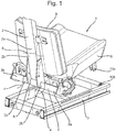
- FIG 2 there is shown a seat 11, with a quick release clamp 15, which clamps first supports 13a to second supports 13b.
- the first supports 13a form a part of a structural support 13, which is part of the base element 18.
- the second supports 13b form part of the back element 12, such that when the quick release clamp is removed, the back element 12 may be removed in its entirety, to allow facile removal of an occupant (not shown) in the seat 11.
- FIG. 3a-c shows a dual quick release mechanical clamp 30, the clamps being linked by an elongate support 35.
- the quick release mechanical clamp 30 comprises at least two clamping surfaces 40, 41 suitable for engagement with structural members(not shown).
- the clamping surfaces 40 and 41 are connected by a hinge member 42.
- a clamp bar 39 has a generally T-shaped profile and protrusions 37 engage with a recess 38 on the outer surface of the first clamping surface 40.
- a release lever 31 impinges upon the outer surface of the second clamp surface 41, and the release lever is temporarily secured to at least one second clamping surface typically using a sprung pin (not shown).
- a tensioner 33 which is in the form of a threaded nut, cooperatively engages with a threaded portion on the clamp bar 39, so as to apply tension to the clamp bar to secure the at least two clamping surfaces 40 and 41, such that they secure fasten to the structural members( figure 2 ).
- the clamp bar 39 comprises a trunion 34, to which is pivotally connected the release lever 31.
- the release lever comprises a cam outer surface 36, such that in the first position as shown tightening of the tensioner 33 pulls the first clamping surface 40 and second clamping surfaces 41 together.
- the release lever Upon removal of the sprung pin the release lever is moved away from the clamp surface by rotating about the trunion 34, to a second position (not shown), which moved the cam to a lower position and removes the tension in the clamp bar 39, thereby allowing the first clamping surface 40 and second clamping surfaces 41 to be removed from the structural members ( figure 2 )
Priority Applications (5)
| Application Number | Priority Date | Filing Date | Title |
|---|---|---|---|
| EP16275161.4A EP3318445A1 (de) | 2016-11-08 | 2016-11-08 | Sitzauslösungssystem |
| PCT/GB2017/053208 WO2018087518A1 (en) | 2016-11-08 | 2017-10-25 | Seat release system |
| EP17791446.2A EP3538397A1 (de) | 2016-11-08 | 2017-10-25 | Sitzauslösungssystem |
| AU2017359552A AU2017359552A1 (en) | 2016-11-08 | 2017-10-25 | Seat release system |
| US16/348,366 US20200062144A1 (en) | 2016-11-08 | 2017-10-25 | Seat release system |
Applications Claiming Priority (1)
| Application Number | Priority Date | Filing Date | Title |
|---|---|---|---|
| EP16275161.4A EP3318445A1 (de) | 2016-11-08 | 2016-11-08 | Sitzauslösungssystem |
Publications (1)
| Publication Number | Publication Date |
|---|---|
| EP3318445A1 true EP3318445A1 (de) | 2018-05-09 |
Family
ID=57326334
Family Applications (1)
| Application Number | Title | Priority Date | Filing Date |
|---|---|---|---|
| EP16275161.4A Ceased EP3318445A1 (de) | 2016-11-08 | 2016-11-08 | Sitzauslösungssystem |
Country Status (1)
| Country | Link |
|---|---|
| EP (1) | EP3318445A1 (de) |
Citations (4)
| Publication number | Priority date | Publication date | Assignee | Title |
|---|---|---|---|---|
| US5269589A (en) * | 1991-01-25 | 1993-12-14 | Bertrand Faure Ltd. | Snap lock fitting for automotive seat backs |
| DE19942976A1 (de) * | 1999-09-09 | 2001-03-22 | Keiper Gmbh & Co | Fahrzeugsitz mit Schnellmontageverbindung |
| DE102007042285A1 (de) * | 2007-02-19 | 2008-08-21 | Johnson Controls Gmbh | Fahrzeugsitz und Montageverfahren |
| GB2462706A (en) * | 2008-08-22 | 2010-02-24 | Mountway Ltd | A detachable seat arrangement with a guide to facilitate correct connection |
-
2016
- 2016-11-08 EP EP16275161.4A patent/EP3318445A1/de not_active Ceased
Patent Citations (4)
| Publication number | Priority date | Publication date | Assignee | Title |
|---|---|---|---|---|
| US5269589A (en) * | 1991-01-25 | 1993-12-14 | Bertrand Faure Ltd. | Snap lock fitting for automotive seat backs |
| DE19942976A1 (de) * | 1999-09-09 | 2001-03-22 | Keiper Gmbh & Co | Fahrzeugsitz mit Schnellmontageverbindung |
| DE102007042285A1 (de) * | 2007-02-19 | 2008-08-21 | Johnson Controls Gmbh | Fahrzeugsitz und Montageverfahren |
| GB2462706A (en) * | 2008-08-22 | 2010-02-24 | Mountway Ltd | A detachable seat arrangement with a guide to facilitate correct connection |
Similar Documents
| Publication | Publication Date | Title |
|---|---|---|
| US7806452B2 (en) | Adjustable security partition for a vehicle | |
| RU2571970C2 (ru) | Кронштейн для крепления периферийных устройств к транспортному средству (варианты) | |
| EP1728930A3 (de) | Lasttragestruktur für die Kabine einer Baumaschine | |
| US10543760B2 (en) | Vehicle seat | |
| AU2016254656A1 (en) | Winch mounting apparatus | |
| CN105291897A (zh) | 用于车辆的锁定座椅的折叠状态的装置 | |
| JP2019038459A (ja) | スライド装置 | |
| EP1787857A3 (de) | Feststellvorrichtung für eine abklappbare Fahrzeugrücksitzrückenlehne, Struktur einer abklappbaren Rücksitzrückenlehne und Feststell- und Entsperrsystem einer abklappbaren Rücksitzrückenlehne | |
| EP3318445A1 (de) | Sitzauslösungssystem | |
| US20200062144A1 (en) | Seat release system | |
| DK2373519T3 (en) | MINES-SECURE INTEGRATION OF COMMERCIAL AVAILABLE SEATS | |
| GB2555789A (en) | Seat release system | |
| US10569676B1 (en) | Fixed seat dampener | |
| WO2006005965A1 (en) | Seating apparatus for use on a vehicle having a flat carrying area | |
| US9079544B2 (en) | Accessory mounting apparatus for a vehicle | |
| US8251410B1 (en) | Armor hold-down assembly | |
| US5692778A (en) | Motor vehicle steering column | |
| CN111372814B (zh) | 具有位置约束的飞行器乘客座椅腿防振件 | |
| FR2945027A1 (fr) | Cloison d'arret pour aeronef et procede d'installation d'une telle cloison | |
| JP2018154325A (ja) | 物品取付器具、移動体装置、物品取付方法及び物品取付器具装着方法 | |
| JP5430953B2 (ja) | 斜張ワイヤーを備えた車両用シートのバックシートフレーム構造および該バックシートフレーム構造を備えた車両用シート | |
| JP5355027B2 (ja) | ヘッドレスト作動装置及びその取付方法 | |
| KR20190141897A (ko) | 탈착시트의 록킹 장치 및 탈착 방법 | |
| JP4773229B2 (ja) | 跳ね上げ式収納シートの取付構造 | |
| DE202015008385U1 (de) | Kamerahalterung für PKW, die an der Kopfstütze befestigt wird. |
Legal Events
| Date | Code | Title | Description |
|---|---|---|---|
| PUAI | Public reference made under article 153(3) epc to a published international application that has entered the european phase |
Free format text: ORIGINAL CODE: 0009012 |
|
| AK | Designated contracting states |
Kind code of ref document: A1 Designated state(s): AL AT BE BG CH CY CZ DE DK EE ES FI FR GB GR HR HU IE IS IT LI LT LU LV MC MK MT NL NO PL PT RO RS SE SI SK SM TR |
|
| AX | Request for extension of the european patent |
Extension state: BA ME |
|
| STAA | Information on the status of an ep patent application or granted ep patent |
Free format text: STATUS: THE APPLICATION HAS BEEN REFUSED |
|
| 18R | Application refused |
Effective date: 20180610 |