EP3318238B1 - Stationswagen - Google Patents
Stationswagen Download PDFInfo
- Publication number
- EP3318238B1 EP3318238B1 EP17200187.7A EP17200187A EP3318238B1 EP 3318238 B1 EP3318238 B1 EP 3318238B1 EP 17200187 A EP17200187 A EP 17200187A EP 3318238 B1 EP3318238 B1 EP 3318238B1
- Authority
- EP
- European Patent Office
- Prior art keywords
- plate
- cabinet
- support
- frame construction
- roller
- Prior art date
- Legal status (The legal status is an assumption and is not a legal conclusion. Google has not performed a legal analysis and makes no representation as to the accuracy of the status listed.)
- Active
Links
Images

Classifications
-
- A—HUMAN NECESSITIES
- A61—MEDICAL OR VETERINARY SCIENCE; HYGIENE
- A61G—TRANSPORT, PERSONAL CONVEYANCES, OR ACCOMMODATION SPECIALLY ADAPTED FOR PATIENTS OR DISABLED PERSONS; OPERATING TABLES OR CHAIRS; CHAIRS FOR DENTISTRY; FUNERAL DEVICES
- A61G12/00—Accommodation for nursing, e.g. in hospitals, not covered by groups A61G1/00 - A61G11/00, e.g. trolleys for transport of medicaments or food; Prescription lists
- A61G12/001—Trolleys for transport of medicaments, food, linen, nursing supplies
-
- A—HUMAN NECESSITIES
- A61—MEDICAL OR VETERINARY SCIENCE; HYGIENE
- A61B—DIAGNOSIS; SURGERY; IDENTIFICATION
- A61B50/00—Containers, covers, furniture or holders specially adapted for surgical or diagnostic appliances or instruments, e.g. sterile covers
- A61B50/10—Furniture specially adapted for surgical or diagnostic appliances or instruments
- A61B50/13—Trolleys, e.g. carts
Definitions
- the invention relates to a station wagon, in particular a visit car for hospitals, nursing homes and other health care facilities with a movable by means of support rollers Schrankunterteil that serves to accommodate utensils, and a cabinet shell, which is relatively movable in height direction formed to Schrankunterteil.
- Station wagon in general and in the special embodiment as a visiting and / or nursing car are well known in the art, such.
- a generic station wagon discloses the DE 20 2012 104 323 U1 ,
- the DE 196 42 523 A1 also relates to a generic station wagon with a cabinet body, which has a covering tray at the top.
- the cabinet body consists of side walls, which have an elongated profile at the corners, in which roles are inserted.
- the DE 202 15 370 U1 shows a carriage for surgical purposes, the rollers are arranged for the movement on a base plate.
- station wagon of the type mentioned in everyday use have proven useful, there is a constant effort to simplify the handling of such cars by design further. It is therefore the object of the invention to develop a generic station wagon to the effect that the design is a user-side simplification in handling is achieved.
- a station wagon of the type mentioned is proposed with the invention, which is characterized in that the Schrankunterteil has a support frame construction with vertically extending struts, wherein each support strut one profile element is arranged, which provides a cavity in the one Spigot of a supporting role is used, wherein a supporting frame construction supporting roller side covering plate is provided, between the support roller side ends of the profile elements and a roller block of the respective on the profile element arranged carrying roller is arranged.
- the cabinet door has a support frame construction, which serves as a self-supporting chassis. In the intended use case occurring loads are derived on this support frame construction and thus standing in operative connection support rollers in the ground on which the station wagon stands.
- the support frame construction has support struts which extend vertically in the intended application of the station trolley according to the invention. These support struts are preferably designed to extend along the corner edges of the cabinet core part. In the final assembled state side wall parts are attached to the support struts, which limit the space provided by the cabinet part receiving space.
- Each support strut a profile element is provided, which is arranged on the associated support strut.
- the profile element is formed for example as a round profile, at least circumferentially sections.
- the profile element provides a cavity into which a journal of a carrying roller is inserted in the final assembled state of the station wagon.
- the support roller preferably has a roller block on which on the one hand the pin and on the other hand wheel discs are rotatably arranged.
- the station wagon is movable on the arranged at the cabinet door part carrying rollers.
- the power dissipation via the support frame construction in the associated profile elements and the support rollers arranged thereon.
- the station wagon according to the invention has a plate which covers the supporting frame construction supporting roller side. By means of this plate, the support frame construction is formed closed at the bottom.
- the special feature according to the invention consists, inter alia, in the fact that this plate, which covers the supporting frame construction, is arranged between the supporting roller-side ends of the profiled elements on the one hand and the roller blocks of the supporting rollers arranged on the profiled elements.
- the support frame construction is designed as a self-supporting chassis, which dissipates forces occurring in the load case on the profile elements arranged thereon and the support rollers directly.
- the arranged between the profile elements and the support rollers plate so neither contributes to the stiffening of the overall construction, nor is it used in the intended use of the recording and derivation of loading forces.
- the construction according to the invention proves to be advantageous in terms of the manufacturer in that a simplified assembly is achieved.
- a non-load-bearing and non-permissive in the intended use case component requires no special fixation and / or assembly steps in the production.
- the plate has through holes through which in the final assembled state engaging in the profile elements pins of the support rollers are guided.
- the construction according to the invention also makes it possible to easily replace the plate if necessary. This may be necessary, for example, because the plate is damaged or so contaminated as a result of intended use during the period of use, that a visually appealing cleaning result can not be achieved.
- the construction according to the invention is particularly advantageous insofar as the carrying rollers are readily accessible from the outside, for example for achieving a parking brake which is typically foot-operated.
- the volume space provided for accommodating utensils on the cabinet side is maximized, since the carrying rollers are arranged on the profile elements which, in the final assembled state of the station cart, are designed so as to extend, as it were, outside the cabinet part.
- Another advantage in this context is the robust overall construction, which ensures a long service life.
- the arrangement of the support rollers on the profile elements ensures that a permanently secure and durable connection is created.
- the plate projects beyond the support frame construction at least partially laterally to form supernatants.
- the plate in plan is greater than the support frame construction. In the final assembled state, the plate thus protrudes laterally beyond the support frame construction.
- This embodiment has the advantage that the station cart can be operated on the user side with the foot during movement.
- the overhanging plate serves the user as a secure Aufsetzkant, which facilitates an operation by means of a user-side foot.
- the plate projection is preferably provided in the region of each support roller according to a further feature of the invention.
- the plate overhang acts in the area of a carrying roller as a roller, and thus as a ramming protection. Additional Rammschutz wornen therefore does not need according to this particular embodiment of the invention.
- a synergistic effect is achieved inasmuch as the plate not only serves to cover the support frame construction on the underside, but at the same time serves as a ramming protection.
- the support frame construction carries on the plate side spaced from the plate arranged inner bottom.
- the inner bottom is preferably connected to the support frame construction, preferably screwed, whereby an additional stiffening of the support frame construction is achieved.
- the inner bottom serves to provide the actual receiving surface for receiving items to be accommodated by the cabinet part.
- the inner bottom is the user-visually perceptible bottom surface.
- the inner bottom is arranged at a distance from the plate covering the supporting frame structure on the underside, so that a cavity is formed between the inner bottom and the plate.
- This cavity serves according to a further feature of the invention to accommodate cables or cable strands, as is typically the case with equipment the station wagon to be laid or to be accommodated with a computer system.
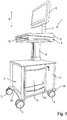
- FIG. 1 shows the station cart 1 according to the invention in a perspective view.
- This has a cabinet door part 2 and a cabinet shell 4.
- the cabinet top 4 is supported by a telescoping column 6, which allows the cabinet top 4 in the vertical direction 5 relative to the cabinet part 2 to move.
- the station cart 1 is designed to be movable, for which purpose support rollers 3 are provided, which are arranged on the underside of the cabinet door part 2.
- the station cart 1 is equipped with a computer system not shown in detail.
- the cabinet part 2 has a storage compartment 11 which can be closed by means of a door. Furthermore, the cabinet part 2 has two drawers 12 and 13. In this case, the drawer 12 provides such a size which is suitable for accommodating so-called findings collection pockets.
- the storage compartment 11, however, serves to accommodate a computer unit.
- a column 7 is arranged, which carries a monitor 8 end.
- This is communication technology connected to the hosted by the storage compartment 11 computer unit.
- peripherals such. B. a mouse or keyboard connected, which are in the non-use case in a provided by the cabinet top 4 storage compartment 10, from which they are in the use case can be out.
- the cabinet part 2 has a self-supporting support frame construction 14, as they are purely schematic in FIG. 2 is shown.
- This support frame construction 14 has four support struts 15, 16, 17 and 18 which each form a corner edge of the cabinet core part 2.
- the support struts 15, 16, 17 and 18 disposed thereon side plates, as the final assembled state of the station cart 1 after FIG. 1 lets recognize.
- Each of the support struts 15 to 18 is associated with a profile element 19, wherein the better overview because of FIG. 2 only the support strut 15 associated profile element 19 can be seen.
- This profile element 19 is formed in the circumferential direction at least partially circular. It is bolted to the respective associated support strut in the final assembled state, so that a firm and secure arrangement of the profile element is given to the associated support strut.
- a support roller 3 is arranged.
- a support roller 3 has a roller block 20, which on the one hand rotatably receives wheel disks and on the other hand provides a pin 21.
- the pin 21 of each support roller 3 is inserted into a cavity provided by the respective profile element 19.
- To secure the position of the pin 21 is screwed by means of a transverse to the pin 21 aligned screw with the profile element 19. It is created as a durable safe and stable and thus overall robust overall construction.
- the support frame construction 14 is covered on the underside by means of a plate 22.
- the plate 22 is arranged in the final assembled state between the support roller-side ends of the profile elements 19 on the one hand and the roller blocks 20 of the respective support rollers 3 arranged on the profile elements 19.
- the plate 22 has holes 23 through which the respectively associated pins 21 of the support rollers 3 are guided.
- FIG. 1 results in the plate 22 on the support frame construction 14 at least partially over and forms in particular in the region of each support roller 3 projections 24.
- These supernatants 24 serve as Bumper.
- FIG. 1 results, are the front access to the cabinet part 2 and the viewing direction of the monitor 8 at a 90 ° angle. This makes it easier for a user to work because it is not necessary to access the cabinet upper part 2 to leave the working position in front of the cabinet top 4.
- the drawers can be opened and closed as intended, with respect to the viewing direction of the monitor 8 for opening to the right or for closing to the left.
- the plate 22 is formed waisted between the two support rollers 3. In the same way, the plate 22 opposite and the support frame construction 14 top closing cover plate is also formed waisted.
- FIG. 1 On the one hand, thanks to the entrained computer unit, it is designed to be used in purely digital mode. On the other hand, the cabinet part 2 provides sufficient volume space to be able to also carry paper documents, for example patient files.
- the station cart 1 according to the invention is therefore suitable both for analog and for digital operation.
Landscapes
- Health & Medical Sciences (AREA)
- Life Sciences & Earth Sciences (AREA)
- Veterinary Medicine (AREA)
- Animal Behavior & Ethology (AREA)
- Engineering & Computer Science (AREA)
- Biomedical Technology (AREA)
- Surgery (AREA)
- Public Health (AREA)
- General Health & Medical Sciences (AREA)
- Heart & Thoracic Surgery (AREA)
- Molecular Biology (AREA)
- Medical Informatics (AREA)
- Nuclear Medicine, Radiotherapy & Molecular Imaging (AREA)
- Nursing (AREA)
- Handcart (AREA)
- Accommodation For Nursing Or Treatment Tables (AREA)
Description
- Die Erfindung betrifft einen Stationswagen, insbesondere einen Visitenwagen für Krankenhäuser, Pflegeheime und sonstige Einrichtungen des Gesundheitswesens mit einem mittels Tragrollen fahrbar ausgebildeten Schrankunterteil, das der Aufnahme von Utensilien dient, und einem Schrankoberteil, das in Höhenrichtung relativ verfahrbar zum Schrankunterteil ausgebildet ist.
- Stationswagen im Allgemeinen sowie in der speziellen Ausgestaltungsform als Visiten- und/oder Pflegewagen sind aus dem Stand der Technik an sich gut bekannt, so z. B. aus der
DE 20 2013 104 564 U1 und derDE 20 2015 106 146 U1 . Einen gattungsgemäßen Stationswagen offenbart dieDE 20 2012 104 323 U1 . - Die
DE 196 42 523 A1 betrifft ebenfalls einen gattungsgemäßen Stationswagen mit einem Schrankkorpus, welcher nach oben hin eine abdeckende Ablage aufweist. Der Schrankkorpus besteht aus Seitenwänden, welche an den Ecken ein langgestrecktes Profil aufweisen, in welche Rollen eingesteckt sind. - Die
DE 202 15 370 U1 zeigt einen Wagen für chirurgische Zwecke, dessen Rollen für die Verfahrbewegung an einer Bodenplatte angeordnet sind. - Obgleich sich Stationswagen der eingangs genannten Art im alltäglichen Praxiseinsatz bewährt haben, besteht das ständige Bestreben, die Handhabung derartiger Wagen konstruktionsbedingt weiter zu vereinfachen. Es ist deshalb die Aufgabe der Erfindung, einen gattungsgemäßen Stationswagen dahingehend weiterzuentwickeln, dass konstruktionsbedingt eine verwenderseitige Vereinfachung in der Handhabung erreicht ist.
- Zur Lösung dieser Aufgabe wird mit der Erfindung ein Stationswagen der eingangs genannten Art vorgeschlagen, der sich dadurch auszeichnet, dass das Schrankunterteil eine Tragrahmenkonstruktion mit vertikal verlaufenden Stützstreben aufweist, wobei an jeder Stützstrebe jeweils ein Profilelement angeordnet ist, das einen Hohlraum bereitstellt, in den ein Zapfen einer Tragrolle eingesetzt ist, wobei eine die Tragrahmenkonstruktion tragrollenseitig abdeckende Platte vorgesehen ist, die zwischen den tragrollenseitigen Enden der Profilelemente und einem Rollenbock der jeweiligen an dem Profilelement angeordneten Tragrolle angeordnet ist.
- Das Schrankunterteil verfügt über eine Tragrahmenkonstruktion, die quasi als selbsttragendes Chassis dient. Im bestimmungsgemäßen Verwendungsfall auftretenden Belastungen werden über diese Tragrahmenkonstruktion und die damit in Wirkverbindung stehenden Tragrollen in den Untergrund abgeleitet, auf dem der Stationswagen steht.
- Die Tragrahmenkonstruktion verfügt über Stützstreben, die im bestimmungsgemäßen Anwendungsfall des erfindungsgemäßen Stationswagens vertikal verlaufen. Diese Stützstreben sind bevorzugterweise entlang der Eckkanten des Schrankunterteils verlaufend ausgebildet. Im endmontierten Zustand sind an den Stützstreben Seitenwandteile angebracht, die den vom Schrankunterteil bereitgestellten Aufnahmeraum begrenzen.
- Je Stützstrebe ist ein Profilelement vorgesehen, das an der zugehörigen Stützstrebe angeordnet ist. Das Profilelement ist beispielsweise als Rundprofil ausgebildet, zumindest umfangsabschnittsweise. Das Profilelement stellt einen Hohlraum bereit, in den im endmontierten Zustand des Stationswagens ein Zapfen einer Tragrolle eingesetzt ist. Dabei weist die Tragrolle bevorzugterweise einen Rollenbock auf, an dem einerseits der Zapfen und andererseits Radscheiben verdrehbar angeordnet sind.
- Im bestimmungsgemäßen Verwendungsfall steht der Stationswagen verfahrbar auf den am Schrankunterteil angeordneten Tragrollen. Dabei erfolgt im Belastungsfall die Kraftableitung über die Tragrahmenkonstruktion in die damit verbundenen Profilelemente und die daran angeordneten Tragrollen.
- Der Stationswagen verfügt erfindungsgemäß über eine Platte, die die Tragrahmenkonstruktion tragrollenseitig abdeckt. Mittels dieser Platte ist die Tragrahmenkonstruktion nach unten hin verschlossen ausgebildet.
- Die erfindungsgemäße Besonderheit besteht unter anderem darin, dass diese die Tragrahmenkonstruktion unterseitig abdeckende Platte zwischen den tragrollenseitigen Enden der Profilelemente einerseits und den Rollenböcken der an den Profilelementen angeordneten Tragrollen angeordnet ist.
- Aufgrund der Zwischenordnung der Platte zwischen den Profilelementen einerseits und den Tragrollen andererseits ist sichergestellt, dass die Platte selbst kein die Konstruktion stützendes Element ist. Die Tragrahmenkonstruktion ist als selbsttragendes Chassis ausgebildet, das im Belastungsfall auftretende Kräfte über die daran angeordneten Profilelemente und die Tragrollen direkt ableitet. Die zwischen den Profilelementen und den Tragrollen angeordnete Platte trägt also weder zur Aussteifung der Gesamtkonstruktion bei, noch dient sie im bestimmungsgemäßen Verwendungsfall der Aufnahme und Ableitung von Belastungskräften.
- Die erfindungsgemäße Konstruktion erweist sich herstellerseitig insofern von Vorteil, als dass eine vereinfachte Montage erreicht ist. Als nicht tragendes und im bestimmungsgemäßen Verwendungsfalle nicht kraftableitendes Bauteil bedarf es keiner besonderen Fixierung und/oder Montageschritte bei der Herstellung. Im einfachsten Fall verfügt die Platte über Durchgangsbohrungen, durch die hindurch im endmontierten Zustand die in die Profilelemente eingreifenden Zapfen der Tragrollen geführt sind. Die erfindungsgemäße Konstruktion gestattet es auch, die Platte im Bedarfsfall einfach austauschen zu können. Dies kann beispielsweise deshalb erforderlich sein, weil die Platte infolge einer bestimmungsgemäßen Benutzung im Laufe der Benutzungszeit beschädigt oder derart verschmutzt wird, dass ein optisch ansprechendes Reinigungsergebnis nicht mehr erreicht werden kann.
- Verwenderseitig ist die erfindungsgemäße Konstruktion insbesondere insofern von Vorteil, als dass die Tragrollen von außen gut zugänglich sind, beispielsweise für ein Erreichen einer typischerweise fußbetätigbaren Feststellbremse. Darüber hinaus ist der zur Aufnahme von Utensilien schrankunterteilseitig bereitgestellte Volumenraum maximiert, da die Tragrollen an den Profilelementen angeordnet sind, die im endmontierten Zustand des Stationswagens quasi außerhalb des Schrankunterteils verlaufend ausgebildet sind. Von weiterem Vorteil ist in diesem Zusammenhang die robuste Gesamtkonstruktion, womit eine lange Lebensdauer gewährleistet ist. Insbesondere sorgt die Anordnung der Tragrollen an den Profilelementen dafür, dass eine dauerhaft sichere und haltbare Verbindung geschaffen ist. Eine solch sichere und haltbare Verbindung wird bei aus dem Stand der Technik bekannten Konstruktionen, gemäß welcher die untere Platte als tragendes Element dient, an dem die Tragrollen direkt angeordnet sind, nicht erreicht. Denn im Belastungsfall können die Tragrollen aus der Platte ausreißen, was bei der erfindungsgemäßen Konstruktion dank der Anordnung der Tragrollen an den Profilelementen nicht möglich ist.
- Es ist gemäß einem weiteren Merkmal der Erfindung vorgesehen, dass die Platte die Tragrahmenkonstruktion unter Ausbildung von Überständen seitlich zumindest abschnittsweise überragt. Gemäß diesem Vorschlag der Erfindung ist also vorgesehen, dass die Platte im Grundriss größer als die Tragrahmenkonstruktion ist. Im endmontierten Zustand steht die Platte also über die Tragrahmenkonstruktion seitlich vor. Diese Ausgestaltung hat den Vorteil, dass der Stationswagen im Verfahrfall verwenderseitig mit dem Fuß betätigt werden kann. Die überstehende Platte dient dem Verwender als sicherer Aufsetzkant, was eine Betätigung mittels eines verwenderseitigen Fußes erleichtert.
- Der Plattenüberstand ist gemäß einem weiteren Merkmal der Erfindung vorzugsweise im Bereich einer jeden Tragrolle bereitgestellt. Der Plattenüberstand wirkt im Bereich einer Tragrolle als Rollen-, mithin als Rammschutz. Zusätzliche Rammschutzeinrichtungen bedarf es gemäß dieser besonderen Ausgestaltung der Erfindung also nicht. Mit dieser Weiterbildung der Erfindung wird insofern auch ein synergetischer Effekt erreicht, da die Platte nicht nur dazu dient, die Tragrahmenkonstruktion unterseitig abzudecken, sondern sie dient gleichzeitig auch als Rammschutz.
- Es ist gemäß einem weiteren Merkmal der Erfindung vorgesehen, dass die Tragrahmenkonstruktion plattenseitig einen zur Platte beabstandet angeordneten Innenboden trägt. Der Innenboden ist bevorzugterweise mit der Tragrahmenkonstruktion verbunden, vorzugsweise verschraubt, wodurch eine zusätzliche Aussteifung der Tragrahmenkonstruktion erreicht ist. Im bestimmungsgemäßen Verwendungsfall dient der Innenboden zur Bereitstellung der eigentlichen Aufnahmefläche zur Aufnahme von vom Schrankunterteil zu beherbergenden Utensilien. Damit stellt der Innenboden die verwenderseitig optisch wahrnehmbare Bodenfläche dar.
- Der Innenboden ist zu der die Tragrahmenkonstruktion unterseitig abdeckenden Platte beabstandet angeordnet, so dass zwischen dem Innenboden und der Platte ein Hohlraum ausgebildet ist. Dieser Hohlraum dient gemäß einem weiteren Merkmal der Erfindung dazu, Kabel oder Kabelstränge aufzunehmen, wie sie typischerweise bei einer Ausstattung des Stationswagens mit einer Rechneranlage zu verlegen bzw. unterzubringen sind.
- Weitere Merkmale und Vorteile der Erfindung ergeben sich aus der nachfolgenden Beschreibung anhand der Figuren. Dabei zeigen:
- Figur 1
- in schematisch perspektivischer Darstellung einen erfindungsgemäßen Stationswagen und
- Figur 2
- in schematisch perspektivischer Explosionsdarstellung ausschnittsweise Einzelteile des Schrankunterteils.
-
Figur 1 lässt den erfindungsgemäßen Stationswagen 1 in einer perspektivischen Ansicht erkennen. Dieser verfügt über ein Schrankunterteil 2 und ein Schrankoberteil 4. Das Schrankoberteil 4 ist von einer teleskopierbaren Säule 6 getragen, was es gestattet, das Schrankoberteil 4 in Höhenrichtung 5 relativ gegenüber dem Schrankunterteil 2 zu verfahren. - Der Stationswagen 1 ist verfahrbar ausgebildet, zu welchem Zweck Tragrollen 3 vorgesehen sind, die unterseitig am Schrankunterteil 2 angeordnet sind.
- Im dargestellten Ausführungsbeispiel ist der Stationswagen 1 mit einer im Detail nicht näher dargestellten Computeranlage ausgerüstet.
- Das Schrankunterteil 2 verfügt über ein Staufach 11, das mittels einer Tür verschließbar ist. Ferner verfügt das Schrankunterteil 2 über zwei Schubladen 12 und 13. Dabei stellt die Schublade 12 eine solche Größe bereit, die dafür geeignet ist, sogenannte Befundsammeltaschen aufnehmen zu können. Das Staufach 11 dient indes der Aufnahme einer Rechnereinheit.
- Am Schrankoberteil 4 ist eine Säule 7 angeordnet, die endseitig einen Monitor 8 trägt. Dieser ist kommunikationstechnisch an die vom Staufach 11 beherbergte Rechnereinheit angeschlossen. An die Rechnereinheit sind ferner Peripheriegeräte, wie z. B. eine Maus oder eine Tastatur angeschlossen, die sich im Nicht-Verwendungsfall in einem vom Schrankoberteil 4 bereitgestellten Staufach 10 befinden, aus dem sie im Verwendungsfall herausverfahren werden können.
- Das Schrankunterteil 2 verfügt über eine selbsttragende Tragrahmenkonstruktion 14, wie sie rein schematisch in
Figur 2 dargestellt ist. Diese Tragrahmenkonstruktion 14 verfügt über vier Stützstreben 15, 16, 17 und 18, die jeweils eine Eckkante des Schrankunterteils 2 bilden. Im endmontierten Zustand nehmen die Stützstreben 15, 16, 17 und 18 daran angeordnete Seitenplatten auf, wie dies der endmontierte Zustand des Stationswagens 1 nachFigur 1 erkennen lässt. - Jeder der Stützstreben 15 bis 18 ist ein Profilelement 19 zugeordnet, wobei der besseren Übersicht wegen in
Figur 2 nur das der Stützstrebe 15 zugeordnete Profilelement 19 zu erkennen ist. Dieses Profilelement 19 ist in Umfangsrichtung zumindest abschnittsweise kreisförmig ausgebildet. Es ist mit der jeweils zugehörigen Stützstrebe im endmontierten Zustand verschraubt, so dass eine feste und sichere Anordnung des Profilelements an der zugehörigen Stützstrebe gegeben ist. - Endseitig eines jeden Profilelements 19 ist eine Tragrolle 3 angeordnet. Eine Tragrolle 3 verfügt über einen Rollenbock 20, der einerseits verdrehbar Radscheiben aufnimmt sowie andererseits einen Zapfen 21 bereitstellt. Im endmontierten Zustand ist der Zapfen 21 einer jeden Tragrolle 3 in einen vom jeweiligen Profilelement 19 bereitgestellten Hohlraum eingesteckt. Zur Lagesicherung ist der Zapfen 21 mittels einer quer zum Zapfen 21 ausgerichteten Schraube mit dem Profilelement 19 verschraubt. Es ist so eine dauerhafte sichere und stabile und damit insgesamt robuste Gesamtkonstruktion geschaffen.
- Die Tragrahmenkonstruktion 14 ist unterseitig mittels einer Platte 22 abgedeckt. Dabei ist die Platte 22 im endmontierten Zustand zwischen den tragrollenseitigen Enden der Profilelemente 19 einerseits und den Rollenböcken 20 der jeweiligen an den Profilelementen 19 angeordneten Tragrollen 3 angeordnet. Zu diesem Zweck verfügt die Platte 22 über Bohrungen 23, durch die hindurch die jeweils zugehörigen Zapfen 21 der Tragrollen 3 geführt sind.
- Wie sich insbesondere aus der Darstellung nach
Figur 1 ergibt, steht die Platte 22 über die Tragrahmenkonstruktion 14 zumindest abschnittsweise über und bildet insbesondere im Bereich einer jeden Tragrolle 3 Überstände 24 aus. Diese Überstände 24 dienen als Rammschutz. - Wie sich insbesondere aus der Darstellung nach
Figur 1 ergibt, stehen der frontseitige Zugang zum Schrankunterteil 2 und die Blickrichtung auf den Monitor 8 unter einem 90° Winkel. Dies erleichtert einem Verwender die Arbeitsweise, denn es ist für einen Zugriff auf das Schrankunterteil 2 nicht erforderlich, die Arbeitsstellung vor dem Schrankoberteil 4 zu verlassen. In der typischen Arbeitsposition vor dem Monitor 8 können die Schubladen bestimmungsgemäß geöffnet und geschlossen werden, und zwar mit Bezug auf die Blickrichtung auf den Monitor 8 für ein Öffnen nach rechts bzw. für ein Schließen nach links. - Um insbesondere ein Bedienen der Rechneranlage im Sitzen zu erleichtern, ist die Platte 22 zwischen den beiden Tragrollen 3 tailliert ausgebildet. In gleicher Weise ist auch die der Platte 22 gegenüberliegend und die Tragrahmenkonstruktion 14 oberseitig verschließende Abdeckplatte ebenfalls tailliert ausgebildet.
- Der in
Figur 1 dargestellte Stationswagen stellt eine sogenannte Mischlösung dar. Einerseits ist er dank der mitgeführten Rechnereinheit dafür ausgelegt, im rein digitalen Betrieb verwendet zu werden. Andererseits bietet das Schrankunterteil 2 hinreichend Volumenraum, um auch noch Papierdokumente, beispielsweise Patientenakten mitführen zu können. Der erfindungsgemäße Stationswagen 1 eignet sich deshalb sowohl für den analogen als auch für den digitalen Betrieb. -
- 1
- Stationswagen
- 2
- Schrankunterteil
- 3
- Tragrolle
- 4
- Schrankoberteil
- 5
- Höhenrichtung
- 6
- Säule
- 7
- Säule
- 8
- Monitor
- 9
- Abdeckplatte
- 10
- Staufach
- 11
- Staufach
- 12
- Schublade
- 13
- Schublade
- 14
- Tragrahmenkonstruktion
- 15
- Stützstreben
- 16
- Stützstreben
- 17
- Stützstreben
- 18
- Stützstreben
- 19
- Profilelement
- 20
- Rollenbock
- 21
- Zapfen
- 22
- Platte
- 23
- Bohrungen
- 24
- Überstände
Claims (5)
- Stationswagen, insbesondere Visitenwagen für Krankenhäuser, Pflegeheime und sonstige Einrichtungen des Gesundheitswesens, mit einem mittels Tragrollen (3) fahrbar ausgebildeten Schrankunterteil (2), das der Aufnahme von Utensilien dient, und einem Schrankoberteil (3), das in Höhenrichtung (5) relativ verfahrbar zum Schrankunterteil (2) ausgebildet ist, dadurch gekennzeichnet, dass das Schrankunterteil (2) eine Tragrahmenkonstruktion (14) mit vertikal verlaufenden Stützstreben (15, 16, 17, 18) aufweist, wobei an jeder Stützstrebe (15, 16, 17, 18) jeweils ein Profilelement (19) angeordnet ist, das einen Volumenraum bereitstellt, in den ein Zapfen (21) einer Tragrolle (3) eingesteckt ist, wobei eine die Tragrahmenkonstruktion (14) tragrollenseitig abdeckende Platte (22) vorgesehen ist, die zwischen den tragrollenseitigen Enden der Profilelemente (19) und einem Rollenbock (20) der jeweiligen an dem Profilelement (19) angeordneten Tragrolle (3) angeordnet ist.
- Stationswagen nach Anspruch 1, dadurch gekennzeichnet, dass die Platte (22) die Tragrahmenkonstruktion (14) unter Ausbildung von Überständen (24) seitlich zumindest abschnittsweise überragt.
- Stationswagen nach Anspruch 2, dadurch gekennzeichnet, dass die Platte (22) im Bereich einer jeden Tragrolle (3) jeweils einen Überstand (24) bereitstellt.
- Stationswagen nach einem der vorhergehenden Ansprüche, dadurch gekennzeichnet, dass die Tragrahmenkonstruktion plattenseitig einen zur Platte (22) beabstandet angeordneten Innenboden trägt.
- Stationswagen nach Anspruch 4, dadurch gekennzeichnet, dass der zwischen Platte (22) und Innenboden befindliche Hohlraum der Kabelverlegung dient.
Priority Applications (1)
| Application Number | Priority Date | Filing Date | Title |
|---|---|---|---|
| SI201730044T SI3318238T1 (sl) | 2016-11-08 | 2017-11-06 | Ambulantni voziček |
Applications Claiming Priority (1)
| Application Number | Priority Date | Filing Date | Title |
|---|---|---|---|
| DE202016106241.1U DE202016106241U1 (de) | 2016-11-08 | 2016-11-08 | Stationswagen |
Publications (2)
| Publication Number | Publication Date |
|---|---|
| EP3318238A1 EP3318238A1 (de) | 2018-05-09 |
| EP3318238B1 true EP3318238B1 (de) | 2019-02-13 |
Family
ID=57795296
Family Applications (1)
| Application Number | Title | Priority Date | Filing Date |
|---|---|---|---|
| EP17200187.7A Active EP3318238B1 (de) | 2016-11-08 | 2017-11-06 | Stationswagen |
Country Status (3)
| Country | Link |
|---|---|
| EP (1) | EP3318238B1 (de) |
| DE (1) | DE202016106241U1 (de) |
| SI (1) | SI3318238T1 (de) |
Families Citing this family (3)
| Publication number | Priority date | Publication date | Assignee | Title |
|---|---|---|---|---|
| DE202021102227U1 (de) | 2021-04-26 | 2022-07-29 | Optiplan Gesellschaft für optische Planungsgeräte mit beschränkter Haftung | Stationswagen, insbesondere Visiten- und/oder Pflegewagen |
| DE102021125800A1 (de) | 2021-10-05 | 2023-04-06 | Optiplan Gesellschaft für optische Planungsgeräte mit beschränkter Haftung | Verfahren zum Betrieb eines digitalen Visitenwagens |
| DE202022102614U1 (de) | 2022-05-12 | 2022-05-25 | Optiplan Gesellschaft für optische Planungsgeräte mit beschränkter Haftung | Stationswagen |
Family Cites Families (8)
| Publication number | Priority date | Publication date | Assignee | Title |
|---|---|---|---|---|
| GB2106455A (en) * | 1981-08-25 | 1983-04-13 | Doherty And Sons Limited Edwar | Dismantlable trolley |
| DE29518479U1 (de) | 1995-11-21 | 1996-01-18 | Wagner, Herbert, 40489 Düsseldorf | Pflegewagen |
| US6663202B2 (en) * | 2001-01-25 | 2003-12-16 | Promedica, Inc. | Transportable medical cart and methods of assembly and use thereof |
| DE20215370U1 (de) | 2002-04-05 | 2003-04-03 | Ohio Medical Instrument Co., Inc., Cincinnati, Ohio | Wagen für chirurgische Zwecke |
| DE202011051973U1 (de) | 2011-11-15 | 2011-11-29 | Optiplan Gesellschaft für optische Planungsgeräte mbH | Stationswagen, insbesondere Visiten- und Pflegewagen |
| DE202013104564U1 (de) | 2013-10-09 | 2013-10-17 | Optiplan Gesellschaft für optische Planungsgeräte mbH | Stationswagen, insbesondere Visiten- und Pflegewagen |
| CN203844795U (zh) * | 2014-05-30 | 2014-09-24 | 丽水市人民医院 | 快速刹车的医用推车 |
| DE202015106146U1 (de) | 2015-11-13 | 2015-12-18 | Optiplan Gesellschaft für optische Planungsgeräte mit beschränkter Haftung | Stationswagen |
-
2016
- 2016-11-08 DE DE202016106241.1U patent/DE202016106241U1/de active Active
-
2017
- 2017-11-06 SI SI201730044T patent/SI3318238T1/sl unknown
- 2017-11-06 EP EP17200187.7A patent/EP3318238B1/de active Active
Non-Patent Citations (1)
| Title |
|---|
| None * |
Also Published As
| Publication number | Publication date |
|---|---|
| SI3318238T1 (sl) | 2019-05-31 |
| EP3318238A1 (de) | 2018-05-09 |
| DE202016106241U1 (de) | 2016-12-22 |
Similar Documents
| Publication | Publication Date | Title |
|---|---|---|
| DE202012104323U1 (de) | Stationswagen, insbesondere Visiten- und Pflegewagen | |
| DE202010003310U1 (de) | Zusammenlegbarer Verkaufsbehälter in Form eines Gittertisches | |
| EP3318238A1 (de) | Stationswagen | |
| EP2666452A1 (de) | Stationswagen, insbesondere Visiten- und Pflegewagen | |
| EP2314497B1 (de) | Transportwagen für Reinigungsutensilien | |
| DE102012012882A1 (de) | Mobiles Informations- und Unterhaltungsgerät für Krankenhauspatienten | |
| DE202013104565U1 (de) | Stationswagen, insbesondere Visiten- und Pflegewagen | |
| DE202016009233U1 (de) | Schublade mit absenkbarem Boden und hiermit ausgestattetes Möbelstück, insbesondere Schrank | |
| DE102011016165A1 (de) | Möbel mit wenigstens einer Schiebetür | |
| DE202015106146U1 (de) | Stationswagen | |
| EP3880924B1 (de) | Möbel mit einer anordnung zur führung wenigstens einer falt-schiebe-tür | |
| DE202005013115U1 (de) | Pflegewagen | |
| DE102013102281A1 (de) | Dialysemaschine mit selbsttragendem Maschinengehäuse | |
| EP1676500B1 (de) | Bodenseitiger Schubkasten für ein Stellmöbel | |
| DE202015101357U1 (de) | Höhenverstellbares Bett | |
| EP3804562B1 (de) | Unterbauschublade | |
| DE202013104564U1 (de) | Stationswagen, insbesondere Visiten- und Pflegewagen | |
| DE202010006859U1 (de) | Transportwagen und darauf abgestimmte Transporteinrichtung für Sterilgut | |
| DE202022102614U1 (de) | Stationswagen | |
| DE202014105229U1 (de) | Stationswagen mit ausziehbarem Plattenelement | |
| EP4122438B1 (de) | Stationswagen, insbesondere visiten- und/oder pflegewagen | |
| DE202019101848U1 (de) | Stationswagen mit austauschbaren Schubladen | |
| EP2939565A1 (de) | In einem schrank aufgenommener auszug | |
| DE102014207572A1 (de) | Materialträger für eine Werkstatt oder Fertigungsstätte | |
| EP3144203A1 (de) | Transportwagen für reinigungsutensilien |
Legal Events
| Date | Code | Title | Description |
|---|---|---|---|
| PUAI | Public reference made under article 153(3) epc to a published international application that has entered the european phase |
Free format text: ORIGINAL CODE: 0009012 |
|
| STAA | Information on the status of an ep patent application or granted ep patent |
Free format text: STATUS: REQUEST FOR EXAMINATION WAS MADE |
|
| 17P | Request for examination filed |
Effective date: 20180305 |
|
| AK | Designated contracting states |
Kind code of ref document: A1 Designated state(s): AL AT BE BG CH CY CZ DE DK EE ES FI FR GB GR HR HU IE IS IT LI LT LU LV MC MK MT NL NO PL PT RO RS SE SI SK SM TR |
|
| AX | Request for extension of the european patent |
Extension state: BA ME |
|
| GRAP | Despatch of communication of intention to grant a patent |
Free format text: ORIGINAL CODE: EPIDOSNIGR1 |
|
| STAA | Information on the status of an ep patent application or granted ep patent |
Free format text: STATUS: GRANT OF PATENT IS INTENDED |
|
| INTG | Intention to grant announced |
Effective date: 20181002 |
|
| GRAS | Grant fee paid |
Free format text: ORIGINAL CODE: EPIDOSNIGR3 |
|
| GRAA | (expected) grant |
Free format text: ORIGINAL CODE: 0009210 |
|
| STAA | Information on the status of an ep patent application or granted ep patent |
Free format text: STATUS: THE PATENT HAS BEEN GRANTED |
|
| AK | Designated contracting states |
Kind code of ref document: B1 Designated state(s): AL AT BE BG CH CY CZ DE DK EE ES FI FR GB GR HR HU IE IS IT LI LT LU LV MC MK MT NL NO PL PT RO RS SE SI SK SM TR |
|
| REG | Reference to a national code |
Ref country code: GB Ref legal event code: FG4D Free format text: NOT ENGLISH |
|
| REG | Reference to a national code |
Ref country code: CH Ref legal event code: EP Ref country code: AT Ref legal event code: REF Ref document number: 1095786 Country of ref document: AT Kind code of ref document: T Effective date: 20190215 |
|
| REG | Reference to a national code |
Ref country code: IE Ref legal event code: FG4D Free format text: LANGUAGE OF EP DOCUMENT: GERMAN |
|
| REG | Reference to a national code |
Ref country code: DE Ref legal event code: R096 Ref document number: 502017000751 Country of ref document: DE |
|
| REG | Reference to a national code |
Ref country code: NL Ref legal event code: FP |
|
| REG | Reference to a national code |
Ref country code: LT Ref legal event code: MG4D |
|
| PG25 | Lapsed in a contracting state [announced via postgrant information from national office to epo] |
Ref country code: LT Free format text: LAPSE BECAUSE OF FAILURE TO SUBMIT A TRANSLATION OF THE DESCRIPTION OR TO PAY THE FEE WITHIN THE PRESCRIBED TIME-LIMIT Effective date: 20190213 Ref country code: PT Free format text: LAPSE BECAUSE OF FAILURE TO SUBMIT A TRANSLATION OF THE DESCRIPTION OR TO PAY THE FEE WITHIN THE PRESCRIBED TIME-LIMIT Effective date: 20190613 Ref country code: SE Free format text: LAPSE BECAUSE OF FAILURE TO SUBMIT A TRANSLATION OF THE DESCRIPTION OR TO PAY THE FEE WITHIN THE PRESCRIBED TIME-LIMIT Effective date: 20190213 Ref country code: NO Free format text: LAPSE BECAUSE OF FAILURE TO SUBMIT A TRANSLATION OF THE DESCRIPTION OR TO PAY THE FEE WITHIN THE PRESCRIBED TIME-LIMIT Effective date: 20190513 Ref country code: FI Free format text: LAPSE BECAUSE OF FAILURE TO SUBMIT A TRANSLATION OF THE DESCRIPTION OR TO PAY THE FEE WITHIN THE PRESCRIBED TIME-LIMIT Effective date: 20190213 |
|
| PG25 | Lapsed in a contracting state [announced via postgrant information from national office to epo] |
Ref country code: GR Free format text: LAPSE BECAUSE OF FAILURE TO SUBMIT A TRANSLATION OF THE DESCRIPTION OR TO PAY THE FEE WITHIN THE PRESCRIBED TIME-LIMIT Effective date: 20190514 Ref country code: RS Free format text: LAPSE BECAUSE OF FAILURE TO SUBMIT A TRANSLATION OF THE DESCRIPTION OR TO PAY THE FEE WITHIN THE PRESCRIBED TIME-LIMIT Effective date: 20190213 Ref country code: BG Free format text: LAPSE BECAUSE OF FAILURE TO SUBMIT A TRANSLATION OF THE DESCRIPTION OR TO PAY THE FEE WITHIN THE PRESCRIBED TIME-LIMIT Effective date: 20190513 Ref country code: LV Free format text: LAPSE BECAUSE OF FAILURE TO SUBMIT A TRANSLATION OF THE DESCRIPTION OR TO PAY THE FEE WITHIN THE PRESCRIBED TIME-LIMIT Effective date: 20190213 Ref country code: IS Free format text: LAPSE BECAUSE OF FAILURE TO SUBMIT A TRANSLATION OF THE DESCRIPTION OR TO PAY THE FEE WITHIN THE PRESCRIBED TIME-LIMIT Effective date: 20190613 Ref country code: HR Free format text: LAPSE BECAUSE OF FAILURE TO SUBMIT A TRANSLATION OF THE DESCRIPTION OR TO PAY THE FEE WITHIN THE PRESCRIBED TIME-LIMIT Effective date: 20190213 |
|
| PG25 | Lapsed in a contracting state [announced via postgrant information from national office to epo] |
Ref country code: SK Free format text: LAPSE BECAUSE OF FAILURE TO SUBMIT A TRANSLATION OF THE DESCRIPTION OR TO PAY THE FEE WITHIN THE PRESCRIBED TIME-LIMIT Effective date: 20190213 Ref country code: ES Free format text: LAPSE BECAUSE OF FAILURE TO SUBMIT A TRANSLATION OF THE DESCRIPTION OR TO PAY THE FEE WITHIN THE PRESCRIBED TIME-LIMIT Effective date: 20190213 Ref country code: AL Free format text: LAPSE BECAUSE OF FAILURE TO SUBMIT A TRANSLATION OF THE DESCRIPTION OR TO PAY THE FEE WITHIN THE PRESCRIBED TIME-LIMIT Effective date: 20190213 Ref country code: DK Free format text: LAPSE BECAUSE OF FAILURE TO SUBMIT A TRANSLATION OF THE DESCRIPTION OR TO PAY THE FEE WITHIN THE PRESCRIBED TIME-LIMIT Effective date: 20190213 Ref country code: EE Free format text: LAPSE BECAUSE OF FAILURE TO SUBMIT A TRANSLATION OF THE DESCRIPTION OR TO PAY THE FEE WITHIN THE PRESCRIBED TIME-LIMIT Effective date: 20190213 Ref country code: CZ Free format text: LAPSE BECAUSE OF FAILURE TO SUBMIT A TRANSLATION OF THE DESCRIPTION OR TO PAY THE FEE WITHIN THE PRESCRIBED TIME-LIMIT Effective date: 20190213 Ref country code: RO Free format text: LAPSE BECAUSE OF FAILURE TO SUBMIT A TRANSLATION OF THE DESCRIPTION OR TO PAY THE FEE WITHIN THE PRESCRIBED TIME-LIMIT Effective date: 20190213 |
|
| REG | Reference to a national code |
Ref country code: DE Ref legal event code: R097 Ref document number: 502017000751 Country of ref document: DE |
|
| PG25 | Lapsed in a contracting state [announced via postgrant information from national office to epo] |
Ref country code: SM Free format text: LAPSE BECAUSE OF FAILURE TO SUBMIT A TRANSLATION OF THE DESCRIPTION OR TO PAY THE FEE WITHIN THE PRESCRIBED TIME-LIMIT Effective date: 20190213 Ref country code: PL Free format text: LAPSE BECAUSE OF FAILURE TO SUBMIT A TRANSLATION OF THE DESCRIPTION OR TO PAY THE FEE WITHIN THE PRESCRIBED TIME-LIMIT Effective date: 20190213 |
|
| PLBE | No opposition filed within time limit |
Free format text: ORIGINAL CODE: 0009261 |
|
| STAA | Information on the status of an ep patent application or granted ep patent |
Free format text: STATUS: NO OPPOSITION FILED WITHIN TIME LIMIT |
|
| 26N | No opposition filed |
Effective date: 20191114 |
|
| PG25 | Lapsed in a contracting state [announced via postgrant information from national office to epo] |
Ref country code: TR Free format text: LAPSE BECAUSE OF FAILURE TO SUBMIT A TRANSLATION OF THE DESCRIPTION OR TO PAY THE FEE WITHIN THE PRESCRIBED TIME-LIMIT Effective date: 20190213 |
|
| PG25 | Lapsed in a contracting state [announced via postgrant information from national office to epo] |
Ref country code: LU Free format text: LAPSE BECAUSE OF NON-PAYMENT OF DUE FEES Effective date: 20191106 Ref country code: MC Free format text: LAPSE BECAUSE OF FAILURE TO SUBMIT A TRANSLATION OF THE DESCRIPTION OR TO PAY THE FEE WITHIN THE PRESCRIBED TIME-LIMIT Effective date: 20190213 |
|
| PG25 | Lapsed in a contracting state [announced via postgrant information from national office to epo] |
Ref country code: IE Free format text: LAPSE BECAUSE OF NON-PAYMENT OF DUE FEES Effective date: 20191106 |
|
| PG25 | Lapsed in a contracting state [announced via postgrant information from national office to epo] |
Ref country code: CY Free format text: LAPSE BECAUSE OF FAILURE TO SUBMIT A TRANSLATION OF THE DESCRIPTION OR TO PAY THE FEE WITHIN THE PRESCRIBED TIME-LIMIT Effective date: 20190213 |
|
| PG25 | Lapsed in a contracting state [announced via postgrant information from national office to epo] |
Ref country code: LI Free format text: LAPSE BECAUSE OF FAILURE TO SUBMIT A TRANSLATION OF THE DESCRIPTION OR TO PAY THE FEE WITHIN THE PRESCRIBED TIME-LIMIT Effective date: 20201130 Ref country code: CH Free format text: LAPSE BECAUSE OF FAILURE TO SUBMIT A TRANSLATION OF THE DESCRIPTION OR TO PAY THE FEE WITHIN THE PRESCRIBED TIME-LIMIT Effective date: 20201130 |
|
| REG | Reference to a national code |
Ref country code: CH Ref legal event code: PL |
|
| PG25 | Lapsed in a contracting state [announced via postgrant information from national office to epo] |
Ref country code: HU Free format text: LAPSE BECAUSE OF FAILURE TO SUBMIT A TRANSLATION OF THE DESCRIPTION OR TO PAY THE FEE WITHIN THE PRESCRIBED TIME-LIMIT; INVALID AB INITIO Effective date: 20171106 Ref country code: MT Free format text: LAPSE BECAUSE OF FAILURE TO SUBMIT A TRANSLATION OF THE DESCRIPTION OR TO PAY THE FEE WITHIN THE PRESCRIBED TIME-LIMIT Effective date: 20190213 |
|
| PG25 | Lapsed in a contracting state [announced via postgrant information from national office to epo] |
Ref country code: MK Free format text: LAPSE BECAUSE OF FAILURE TO SUBMIT A TRANSLATION OF THE DESCRIPTION OR TO PAY THE FEE WITHIN THE PRESCRIBED TIME-LIMIT Effective date: 20190213 |
|
| GBPC | Gb: european patent ceased through non-payment of renewal fee |
Effective date: 20211106 |
|
| PG25 | Lapsed in a contracting state [announced via postgrant information from national office to epo] |
Ref country code: GB Free format text: LAPSE BECAUSE OF NON-PAYMENT OF DUE FEES Effective date: 20211106 |
|
| P01 | Opt-out of the competence of the unified patent court (upc) registered |
Effective date: 20230517 |
|
| PGFP | Annual fee paid to national office [announced via postgrant information from national office to epo] |
Ref country code: BE Payment date: 20241120 Year of fee payment: 8 |
|
| PGFP | Annual fee paid to national office [announced via postgrant information from national office to epo] |
Ref country code: FR Payment date: 20241128 Year of fee payment: 8 |
|
| PGFP | Annual fee paid to national office [announced via postgrant information from national office to epo] |
Ref country code: IT Payment date: 20241126 Year of fee payment: 8 |
|
| PGFP | Annual fee paid to national office [announced via postgrant information from national office to epo] |
Ref country code: NL Payment date: 20251119 Year of fee payment: 9 |
|
| PGFP | Annual fee paid to national office [announced via postgrant information from national office to epo] |
Ref country code: AT Payment date: 20251120 Year of fee payment: 9 |
|
| PGFP | Annual fee paid to national office [announced via postgrant information from national office to epo] |
Ref country code: SI Payment date: 20251023 Year of fee payment: 9 |
|
| PGFP | Annual fee paid to national office [announced via postgrant information from national office to epo] |
Ref country code: DE Payment date: 20260129 Year of fee payment: 9 |