EP3317552B1 - Collier d'attache de tuyau muni de vis de serrage ayant un capuchon de limitation de couple - Google Patents
Collier d'attache de tuyau muni de vis de serrage ayant un capuchon de limitation de couple Download PDFInfo
- Publication number
- EP3317552B1 EP3317552B1 EP16745525.2A EP16745525A EP3317552B1 EP 3317552 B1 EP3317552 B1 EP 3317552B1 EP 16745525 A EP16745525 A EP 16745525A EP 3317552 B1 EP3317552 B1 EP 3317552B1
- Authority
- EP
- European Patent Office
- Prior art keywords
- screw
- cap
- screw head
- pipe clip
- torque
- Prior art date
- Legal status (The legal status is an assumption and is not a legal conclusion. Google has not performed a legal analysis and makes no representation as to the accuracy of the status listed.)
- Active
Links
Images


Classifications
-
- F—MECHANICAL ENGINEERING; LIGHTING; HEATING; WEAPONS; BLASTING
- F16—ENGINEERING ELEMENTS AND UNITS; GENERAL MEASURES FOR PRODUCING AND MAINTAINING EFFECTIVE FUNCTIONING OF MACHINES OR INSTALLATIONS; THERMAL INSULATION IN GENERAL
- F16B—DEVICES FOR FASTENING OR SECURING CONSTRUCTIONAL ELEMENTS OR MACHINE PARTS TOGETHER, e.g. NAILS, BOLTS, CIRCLIPS, CLAMPS, CLIPS OR WEDGES; JOINTS OR JOINTING
- F16B31/00—Screwed connections specially modified in view of tensile load; Break-bolts
- F16B31/02—Screwed connections specially modified in view of tensile load; Break-bolts for indicating the attainment of a particular tensile load or limiting tensile load
- F16B31/027—Screwed connections specially modified in view of tensile load; Break-bolts for indicating the attainment of a particular tensile load or limiting tensile load with a bolt head causing the fastening or the unfastening tool to lose the grip when a specified torque is exceeded
-
- F—MECHANICAL ENGINEERING; LIGHTING; HEATING; WEAPONS; BLASTING
- F16—ENGINEERING ELEMENTS AND UNITS; GENERAL MEASURES FOR PRODUCING AND MAINTAINING EFFECTIVE FUNCTIONING OF MACHINES OR INSTALLATIONS; THERMAL INSULATION IN GENERAL
- F16B—DEVICES FOR FASTENING OR SECURING CONSTRUCTIONAL ELEMENTS OR MACHINE PARTS TOGETHER, e.g. NAILS, BOLTS, CIRCLIPS, CLAMPS, CLIPS OR WEDGES; JOINTS OR JOINTING
- F16B31/00—Screwed connections specially modified in view of tensile load; Break-bolts
- F16B31/02—Screwed connections specially modified in view of tensile load; Break-bolts for indicating the attainment of a particular tensile load or limiting tensile load
-
- F—MECHANICAL ENGINEERING; LIGHTING; HEATING; WEAPONS; BLASTING
- F16—ENGINEERING ELEMENTS AND UNITS; GENERAL MEASURES FOR PRODUCING AND MAINTAINING EFFECTIVE FUNCTIONING OF MACHINES OR INSTALLATIONS; THERMAL INSULATION IN GENERAL
- F16L—PIPES; JOINTS OR FITTINGS FOR PIPES; SUPPORTS FOR PIPES, CABLES OR PROTECTIVE TUBING; MEANS FOR THERMAL INSULATION IN GENERAL
- F16L3/00—Supports for pipes, cables or protective tubing, e.g. hangers, holders, clamps, cleats, clips, brackets
- F16L3/08—Supports for pipes, cables or protective tubing, e.g. hangers, holders, clamps, cleats, clips, brackets substantially surrounding the pipe, cable or protective tubing
- F16L3/10—Supports for pipes, cables or protective tubing, e.g. hangers, holders, clamps, cleats, clips, brackets substantially surrounding the pipe, cable or protective tubing divided, i.e. with two members engaging the pipe, cable or protective tubing
- F16L3/1033—Supports for pipes, cables or protective tubing, e.g. hangers, holders, clamps, cleats, clips, brackets substantially surrounding the pipe, cable or protective tubing divided, i.e. with two members engaging the pipe, cable or protective tubing with two members engaging the pipe, cable or tubing, the two members being joined only on one side of the pipe
-
- F—MECHANICAL ENGINEERING; LIGHTING; HEATING; WEAPONS; BLASTING
- F16—ENGINEERING ELEMENTS AND UNITS; GENERAL MEASURES FOR PRODUCING AND MAINTAINING EFFECTIVE FUNCTIONING OF MACHINES OR INSTALLATIONS; THERMAL INSULATION IN GENERAL
- F16L—PIPES; JOINTS OR FITTINGS FOR PIPES; SUPPORTS FOR PIPES, CABLES OR PROTECTIVE TUBING; MEANS FOR THERMAL INSULATION IN GENERAL
- F16L55/00—Devices or appurtenances for use in, or in connection with, pipes or pipe systems
- F16L55/02—Energy absorbers; Noise absorbers
- F16L55/033—Noise absorbers
- F16L55/0336—Noise absorbers by means of sound-absorbing materials
Definitions
- the invention relates to a pipe clip comprising a metal annular clip body having at least two opposing radial flanges defining an opening adapted to arrange the pipe clip body around a pipe, wherein the pipe clip body has at one of the radial flanges a female fastening means and wherein the pipe clip comprises a tightening screw having a screw head and a screw shank, said screw shank being provided with a male thread adapted to cooperate with the female fastening means, and wherein the screw head engages the other of the radial flanges so as to tighten the flanges towards each other and tighten the pipe clip around the pipe, and wherein the pipe clip has a vibration insulating lining provided on the inner side of the annular clip body.
- DE4039260A1 and DE8806714U1 disclose a pipe clip according to the pre-amble of claim 1.
- the invention has for an object to provide an improved pipe clip that removes or at least mitigates the problem of a reduced vibration insulating effect.
- a pipe clip of the type described at the outset wherein a torque limiting cap is arranged on the screw head of the tightening screw, said torque limiting cap including at least one torque transferring feature that couples the cap to the screw head in a rotational direction.
- the torque limiting cap During fitting of the pipe clip the torque limiting cap is engaged by a screw driver.
- the torque limiting cap transfers the torque applied by the screw driver to the screw head and warrants that the tightening screw cannot be tightened beyond a predetermined maximum torque. Hence, the flanges of the pipe clip cannot be tightened towards each other excessively.
- the torque limiting cap By the selection of the specific structure and/or material of the torque limiting cap, it can be designed for a certain optimal vibration insulating function.
- the torque limiting cap according to the invention may have different embodiments.
- the torque limiting cap is made of plastic and has on an inner side a protrusion that mates with a recess in the screw head such that a torque can be transferred from the cap to the screw head, and which plastic cap has on an outer side a recess which is able to mate with a screw driver, wherein the plastic cap is adapted and arranged to be destructed at the recess by the screw driver when the torque applied by a screw driver to the cap exceeds a predetermined value so as to limit the torque to be applied to the screw.
- the choice of the specific plastic material used influences the maximum torque that the cap can transfer to the screw before the recess that mates with the screw driver is destructed.
- the selection of a specific plastic material may advantageously be used to provide different caps with the same design for the same screw, but with a different torque limit.
- the recess in the screw head may be a socket, preferably a hexagonal socket (hex socket).
- the socket, and in particular the hex socket can receive a mating tool tip, which is common tool tip shape.
- the torque limiting cap can be removed and the socket in the screw head can be used to unscrew the tightening screw.
- the recess in the cap has a cruciform shape. This has the advantage that the pipe clip can be tightened with the most common cruciform screw driver heads.
- the torque limiting cap comprises a dome that receives the screw head.
- the dome covers the screw head and prevents that the screw head is directly engaged with a tool or otherwise, whereby the torque limiting function might be circumvented.
- the cap comprises an extension part on top of the dome, wherein the recess, which is able to mate with the screw driver, is arranged in said extension part.
- the peripheral surface of the extension part may have a cylindrical shape or a hexagonal shape.
- the hexagonal outer shape of the extension part provides the option to tighten the combination screw/torque limiting cap by means of a spanner, wrench or other suitable tool.
- the recess in the extension part is not used and will not be destroyed when a certain torque limit is exceeded.
- the cap is designed such that the protrusion located on the inner side of the cap and mating with the socket in the screw head is destroyed when a certain torque limit is exceeded.
- the torque limit determined by the recess in the extension part and the torque limit determined by the protrusion on the inner side of the cap may be different, in particular the latter will be higher than the former. To provide this a hexagonal shape of the protrusion and the socket is advantageous.
- the torque limiting cap is retained on the screw head in the axial direction of the screw and is coupled in a direction of rotation to the screw head by a ratchet mechanism which allows rotation of the cap relative to the screw head in a tightening direction if the torque applied to the cap exceeds a predetermined threshold value and blocks rotation relative to the screw head in an opposite direction.
- the torque transferring feature comprises the ratchet mechanism.
- this torque limiting cap is made of metal, preferably spring steel.
- the torque limiting cap is not destroyed when the torque limit is exceeded.
- the tightening screw with the torque limiting cap can be used and re-used if for some reason the screw has been released and has to be tightened again.
- the screw head has a peripheral surface, a shaft-sided surface and a top surface opposite the shaft sided surface
- the torque limiting cap comprises a top plate that is located at the side of the top surface of the screw head and is provided with a cut-out or recess which is able to mate with a screw driver, and retaining arms that run from the top plate along the peripheral surface of the screw head towards the shaft sided surface, said retaining arms having a hook end that grips behind the edge between the peripheral surface and the shaft sided surface of the screw head, and wherein ramp shaped lugs are formed on the peripheral surface of the head, wherein the ramp shaped lugs and the retaining arms form part of said ratchet mechanism wherein the retaining arms are able to run onto and beyond the ramp shaped lugs in a tightening direction when a predetermined torque is applied to the torque limiting cap and wherein the retaining arms are blocked by the ramp shaped lugs in an untightening direction.
- the screw head is a polygonal head, preferably a hexagonal head, and the ramp shaped lugs are located adjacent the axially extending edges of the polygonal head.
- the screw head has a blind central hole in a top surface, wherein the cut-out or recess in the top plate of the torque limiting cap is aligned with said blind central hole in the screw head.
- the torque limiting cap is retained on the screw head in the axial direction of the screw and in the direction of rotation, wherein the torque limiting cap has a base plate that is arranged on a top side of the screw head, and wings extending from the peripheral edge and are folded over such that they have end portions that extend substantially parallel to the base plate, wherein the peripheral edges of the end portions of the folded wings are spaced apart in such a way that essentially crosswise slots are formed adapted to mate with a screw driver, and wherein the folded wings are adapted and arranged to be elastically deformed by the screw driver when the torque applied by the screw driver to the cap exceeds a predetermined value, such that the screw driver shifts out of the slot(s), so as to limit the torque to be applied to the screw.
- This torque limiting cap is preferably formed from sheet metal, in particular from a spring steel sheet.
- the torque limiting cap is not destroyed when the torque limit is exceeded.
- the tightening screw with the torque limiting cap can be used and re-used if for some reason the screw has been released and has to be tightened again.
- the torque transferring feature comprises a weld or screw connection fixing the torque limiting cap to the screw head.
- the cap has retaining arms that extend from the base plate to an opposite side as the folded wings extend to, which arms extend along the peripheral surface of the screw head, said arms being connected to the screw head, e.g. by welding or screwing.
- the screw head may be cylindrical and provided with a male thread and the arms may be formed as cylinder sections which on their inner side are provided with a female thread able to cooperate with said male thread.
- Fig. 1 shows a pipe clip 1 comprising a metal annular clip body 2.
- the pipe clip 1 has a vibration insulating lining 8 provided on the inner side of the annular clip body 2.
- the clip body 2 has on one side two opposing radial flanges 3, 4 defining an opening 5 adapted to arrange the pipe clip body 2 around a pipe 6. It is possible that the clip body has opposing flanges on both sides which can be tightened together, but this is not essential to the invention.
- the pipe clip body 2 has at the radial flange 4 a female fastening means, in this case formed as a threaded hole in the flange 4.
- the pipe clip 1 comprises a tightening screw 7 having a screw head 7A and a screw shank 7B.
- the screw shank 7B is provided with a male thread adapted to cooperate with the female thread of the hole in the flange 4.
- the screw head 7A engages the other radial flange 3 so as to tighten the flanges 3, 4 towards each other and tighten the pipe clip 1 around the pipe 6.
- a torque limiting cap 9 is arranged on the screw head 7A of the tightening screw 7.
- different tightening screws are described which will be indicated by reference numerals 17, 27 and 37 respectively and the corresponding caps are indicated by reference numerals 19, 29, 39 respectively.
- Figs. 2 - 5 is illustrated an embodiment of a tightening screw 17 with a torque limiting cap 19 made of plastic.
- the torque limiting cap 19 comprises a dome 191 that is positioned over the screw head 17A.
- the screw head 17A has a recess formed as a socket, in particular a hex socket 171.
- a torque transferring protrusion 192 is formed (cf. Fig. 5 ) that mates with a socket 171 in the screw head 17A.
- the protrusion 192 has a hexagonal shape.
- the protrusion 192 mating with the socket 171 forms a torque transferring feature that couples the cap 19 to the screw head 17A in a rotational direction of the screw.
- the cap 19 comprises on an outer side, i.e. the convex side of the dome 191 an extension part 192 on top of the dome 191.
- a recess 193 which is able to mate with a screw driver is formed in the extension part 192.
- the recess has a cruciform shape as can be seen in Figs 2 and 4 .
- the peripheral surface of the extension part 192 has a cylindrical shape as can be seen in Figs 2 and 4 ..
- the plastic cap 19 is formed such that it is destructed at the recess 193 by the screw driver when the torque applied by a screw driver to the cap 19 exceeds a predetermined value so as to limit the torque to be applied to the screw 17.
- a similar screw 17 is shown provided with an alternative cap 19'.
- the only difference with the previous cap 19 is the outer contour of the extension part 192' which is polygonal, in this particular example hexagonal.
- the other features are the same as the cap 19 shown in Figs 2- 5 and are indicated with the same reference numerals.
- the hexagonal outer shape of the extension part 192' provides the option to tighten the combination of the screw 17 and the torque limiting cap 19' by means of a spanner, wrench or other suitable tool.
- the recess in the extension part is not used and will not be destroyed when a certain torque limit is exceeded.
- the cap 19' is designed such that the protrusion 192 located on the inner side of the cap 19' and mating with the socket 171 in the screw head 17A is destroyed when a certain torque limit is exceeded.
- the torque limit determined by the recess 193 in the extension part 192' will be lower than the torque limit determined by the protrusion 192 on the inner side of the cap.
- Fig. 8 - 10 is shown a different embodiment of a tightening screw 27 with torque limiting cap 29.
- the torque limiting cap 29 is retained on the screw head 27A in the axial direction of the screw 27 and is coupled in a direction of rotation to the screw head 27A by a ratchet mechanism which allows rotation of the cap 29 relative to the screw head 27A in a tightening direction 20 if the torque applied to the cap exceeds a predetermined threshold value and blocks rotation relative to the screw head 27A in an opposite direction 21.
- the torque limiting cap 29 in this embodiment is made of metal, preferably spring steel.
- the screw head 27A has a peripheral surface 271, a shaft sided surface 272 and a top surface 273 opposite the shaft sided surface 272.
- the torque limiting cap 29 comprises a top plate 291 that is located at the side of the top surface 273 of the screw head 27 and is provided with a cut-out 292 which is able to mate with a screw driver.
- the cut-out has a cruciform shape in this example.
- the cap 29 has retaining arms 293 that run from the top plate 291 along the peripheral surface 271 of the screw head 27A towards the shaft sided surface 272. In this example the cap has two radially opposing retaining arms, but the cap could have more retaining arms.
- the retaining arms 293 each have a hook end 294 that grips behind the edge 274 between the peripheral surface 271 and the shaft sided surface 272 of the screw head 27A.
- Ramp shaped lugs 273 are formed on the peripheral surface of the screw head 27A.
- the ramp shaped lugs 273 and the retaining arms 293 form part of the mentioned ratchet mechanism wherein the retaining arms 293 are able to run onto and beyond the ramp shaped lugs 273 in a tightening direction (indicated by arrow 20 in Fig. 8 ) when a predetermined torque is applied to the torque limiting cap 29.
- the retaining arms 293 are blocked by a stop surface 273A of the ramp shaped lugs 273 in an untightening direction (indicated by arrow 21 in Fig. 8 ).
- the screw head 27A is a polygonal head, in this particular example a hexagonal head.
- the ramp shaped lugs 273 are located adjacent axially extending edges 275 of the polygonal head 27A.
- the screw head 27A has a blind central hole 276 in the top surface 273.
- the cut-out 292 in the top plate 291 of the torque limiting cap 29 is aligned with said blind central hole 276 in the screw head 27A. This allows that a screw driver tip can be inserted far enough in the cut-out such that the engagement is not the limiting factor on what torque can be applied to the cap 29 and the head 27A.
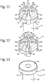
- Fig. 11 - 13 is shown yet another different embodiment of a tightening screw 37 with torque limiting cap 39.
- the screw 37 has a head 37A and a shaft 37B.
- the torque limiting cap 39 is formed from sheet metal, in particular from a spring steel sheet.
- the torque limiting cap 39 in this embodiment is retained on the screw head 37A in the axial direction of the screw 37 and in the direction of rotation.
- the torque limiting cap 39 has a base plate 391 that is arranged on a top side 373 of the screw head 37.
- the cap 39 has wings 394 extending from the peripheral edge of the base plate 391 and are folded over such that they have end portions 395 that extend substantially parallel to the base plate 391.
- the peripheral edges 396 of the end portions of the folded wings 394 are spaced apart in such a way that essentially crosswise slots 397 are formed adapted to mate with a screw driver.
- the folded wings 394 are adapted and arranged to be deformed by the screw driver when the torque applied by the screw driver to the cap 39 exceeds a predetermined value, such that the screw driver shifts out of the slot(s) 397, so as to limit the torque to be applied to the screw 37.
- the cap 39 has arms 393 that extend from the base plate 391 to an opposite side as the folded wings 394 extend to.
- the arms 393 extend along a peripheral surface 371 of the screw head 37A.
- the arms 393 are connected to the screw head 37A.
- the arms 393 may for example be welded to the screw head 37A.
- the peripheral surface 371 of the screw head may be threaded, and the arms 393 may be provided with female thread sections able to cooperate with the male thread on the peripheral surface 371. Thereby the cap 39 can be screwed onto the screw head 37A.
Landscapes
- Engineering & Computer Science (AREA)
- General Engineering & Computer Science (AREA)
- Mechanical Engineering (AREA)
- Connection Of Plates (AREA)
- Clamps And Clips (AREA)
Claims (15)
- Collier d'attache (1) de tuyau comprenant un corps de collier d'attache (2) annulaire métallique ayant au moins deux brides (3, 4) radiales opposées définissant une ouverture (5) adaptée pour agencer le corps de collier d'attache (2) autour d'un tuyau (6), dans lequel le corps de collier d'attache (2) présente à l'une des brides (4) radiales un moyen de fixation femelle et dans lequel le collier d'attache (1) comprend une vis de serrage (7, 17, 27, 37) ayant une tête de vis (7A, 17A, 27A, 37A) et une tige de vis (7B, 17B, 27B, 37B), ladite tige de vis (7B, 17B, 27B, 37B) étant pourvue d'un filetage male apte à coopérer avec le moyen de fixation femelle, et dans lequel la tête de vis (7A, 17A, 27A, 37A) vient en prise avec l'autre des brides (3) radiales de manière à serrer les brides (3, 4) l'une vers l'autre et à serrer le collier d'attache (1) autour du tuyau (6), et dans lequel le collier d'attache (1) présente un revêtement (8) d'isolation vis-à-vis des vibrations prévu sur le côté interne du corps de collier d'attache (2) annulaire, caractérisé en ce que
un capuchon (9, 19, 19', 29, 39) de limitation de couple est disposé sur la tête de vis (7A, 17A, 27A, 37A) de la vis de serrage (7, 17, 27, 37), ledit capuchon de limitation de couple comprenant au moins un élément de transfert de couple (192, 192', 293, 393) qui accouple le capuchon (9, 19, 19', 29, 39) à la tête de vis (7A, 17A, 27A, 37A) dans une direction de rotation. - Collier d'attache (1) de tuyau selon la revendication 1, dans lequel le capuchon (9, 19, 19') de limitation de couple est réalisé en matière plastique et présente sur un côté interne une saillie de transfert de couple (192, 192') qui coopère avec un évidement (171) dans la tête de vis (7A, 17A) de telle sorte qu'un couple peut être transféré du capuchon (9, 19, 19') à la tête de vis (7A, 17A), et lequel capuchon (9, 19, 19') en matière plastique présente sur un côté externe un évidement (193) qui est apte à coopérer avec un tournevis, dans lequel le capuchon (9, 19, 19') en matière plastique est adapté et agencé pour être détruit au niveau de l'évidement (193) par le tournevis lorsque le couple appliqué par un tournevis au capuchon (9, 19, 19') dépasse une valeur prédéterminée de manière à limiter le couple à appliquer à la vis (7, 17).
- Collier d'attache (1) de tuyau selon la revendication 2, dans lequel l'évidement (171) dans la tête de vis (7A, 17A) est une douille, de préférence une douille hexagonale (hex).
- Collier d'attache (1) de tuyau selon la revendication 2, dans lequel l'évidement (193) dans le capuchon (9, 19, 19') a une forme de cruciforme.
- Collier d'attache (1) de tuyau selon l'une quelconque des revendications 2 à 4, dans lequel le capuchon (9, 19, 19') de limitation de couple comprend un dôme (191) qui reçoit la tête de vis (7A, 17A).
- Collier d'attache (1) de tuyau selon la revendication 5, dans lequel le capuchon (9, 19, 19') comprend une partie d'extension (192, 192') au-dessus du dôme (191), dans lequel l'évidement (193), qui est apte à coopérer avec le tournevis, est disposé dans ladite partie d'extension (192, 192'), dans lequel de préférence la surface périphérique de la partie d'extension a une forme cylindrique ou une forme hexagonale.
- Collier d'attache (1) de tuyau selon la revendication 1, dans lequel le capuchon (9, 29) de limitation de couple est retenu sur la tête de vis (7A, 27A) dans la direction axiale de la vis (7, 27) et est couplé dans une direction de rotation à la tête de vis (7A, 27A) par un mécanisme d'encliquetage qui permet la rotation du capuchon (9, 29) par rapport à la tête de vis (7A, 27A) dans une direction de serrage si le couple appliqué au capuchon (9, 29) dépasse une valeur de seuil prédéterminée et bloque la rotation relative de la tête de vis (7A, 27A) dans une direction opposée.
- Collier d'attache (1) de tuyau selon la revendication 7, dans lequel le capuchon (9, 29) de limitation de couple est réalisé en métal, de préférence en acier ressort.
- Collier d'attache de tuyau selon la revendication 7 ou 8, dans lequel la tête de vis (7A, 27A) présente une surface périphérique (271), une surface côté tige (272) et une surface supérieure (273) opposée à la surface côté tige (272), et dans lequel le capuchon (9, 29) de limitation de couple comprend une plaque supérieure (291) qui est située au niveau du côté de la surface supérieure (273) de la tête de vis (7A, 27A) et est pourvue d'une découpe ou un évidement (292) qui est apte à coopérer avec un tournevis, et des bras de retenue (293) qui s'étendent à partir de la plaque supérieure (273) le long de la surface périphérique (271) de la tête de vis (7A, 27A) vers la surface côté tige (272), lesdits bras de retenue (293) ayant une extrémité de crochet (294) qui s'accroche derrière le bord (274) entre la surface périphérique (271) et la surface côté tige (272) de la tête de vis (7A, 27A), et dans lequel des pattes en forme de rampe (273) sont formées sur la surface périphérique (271) de la tête (7A, 27A), dans lequel les pattes en forme de rampe (273) et les bras de retenue (293) forment une partie dudit mécanisme d'encliquetage, dans lequel les bras de retenue (293) sont capables de fonctionner sur et au-delà des pattes en forme de rampe (273) dans une direction de serrage quand un couple prédéterminé est appliqué sur le capuchon (9, 29) de limitation de couple et dans lequel les bras de retenue (293) sont bloqués par les pattes en forme de rampe (273) dans la direction de desserrage.
- Collier d'attache (1) de tuyau selon la revendication 9, dans lequel la tête de vis (7A, 27A) est une tête polygonale, de préférence une tête hexagonale, et dans lequel les pattes en forme de rampe (273) sont situées au voisinage des bords à extension axiale (275) de la tête (7A, 27A) polygonale.
- Collier d'attache (1) de tuyau selon la revendication 9 ou 10, dans lequel la tête de vis (7A, 27A) présente un trou central borgne (276) sur une surface supérieure (273), dans lequel la découpe ou l'évidement (292) dans la plaque supérieure (291) du capuchon (9, 29) de limitation de couple est aligné avec ledit trou central borgne (276) dans la tête de vis (7A, 27A).
- Collier d'attache (1) de tuyau selon la revendication 1, dans lequel le capuchon (9, 39) de limitation de couple est retenu sur la tête de vis (7A, 37A) dans la direction axiale de la vis (7, 37) et dans la direction de rotation, dans lequel le capuchon (9, 39) de limitation de couple comporte une plaque de base (391) qui est disposée sur un côté supérieure (373) de la tête de vis (7A, 37A) et des ailes (394) s'étendant à partir du bord périphérique et qui sont repliées de telle sorte qu'elles présentent des parties d'extrémité (395) qui s'étendent sensiblement parallèlement à la plaque de base (391), dans lequel les bords périphériques (396) des parties d'extrémité (395) des ailes (394) repliées sont espacées de telle sorte que des fentes (397) essentiellement transversales sont formées et adaptés pour coopérer avec un tournevis, et dans lequel les ailes (394) repliées sont adaptées et agencées pour être déformées par le tournevis lorsque le couple appliqué par le tournevis sur le capuchon (9, 39) dépasse une valeur prédéterminée, de telle sorte que le tournevis se décale hors de la (des) fente (s) (397), de manière à limiter le couple à appliquer à la vis (7, 37).
- Collier d'attache de tuyau selon la revendication 12, dans lequel le capuchon (9, 39) de limitation de couple est fixé à la tête de vis (7A, 37A), par soudage ou par assemblage par vis.
- Collier d'attache de tuyau selon la revendication 12 ou 13, dans lequel le capuchon (9, 39) comporte des bras de retenue (393) qui s'étendent à partir de la plaque de base (391) vers un côté opposé, comme s'étendent les ailes (394) repliées, lesquels bras (393) s'étendent le long de la surface périphérique (371) de la tête de vis (7A, 37A), lesdits bras (393) étant reliés à la tête de vis (7A, 37A).
- Collier d'attache de tuyau selon l'une quelconque des revendications 12 à 14, dans lequel le capuchon (9, 39) de limitation de couple est formé à partir de métal en feuille, en particulier à partir d'une feuille en acier ressort.
Priority Applications (1)
| Application Number | Priority Date | Filing Date | Title |
|---|---|---|---|
| PL16745525T PL3317552T3 (pl) | 2015-07-02 | 2016-06-30 | Zacisk rury ze śrubą dociskową mającą nakrętkę ograniczającą moment obrotowy |
Applications Claiming Priority (2)
| Application Number | Priority Date | Filing Date | Title |
|---|---|---|---|
| NL2015075A NL2015075B1 (en) | 2015-07-02 | 2015-07-02 | Pipe clip with tightening screw having torque limiting cap. |
| PCT/NL2016/050463 WO2017003287A1 (fr) | 2015-07-02 | 2016-06-30 | Collier d'attache de tuyau muni de vis de serrage ayant un capuchon de limitation de couple |
Publications (2)
| Publication Number | Publication Date |
|---|---|
| EP3317552A1 EP3317552A1 (fr) | 2018-05-09 |
| EP3317552B1 true EP3317552B1 (fr) | 2020-05-27 |
Family
ID=53783875
Family Applications (1)
| Application Number | Title | Priority Date | Filing Date |
|---|---|---|---|
| EP16745525.2A Active EP3317552B1 (fr) | 2015-07-02 | 2016-06-30 | Collier d'attache de tuyau muni de vis de serrage ayant un capuchon de limitation de couple |
Country Status (7)
| Country | Link |
|---|---|
| US (1) | US10584735B2 (fr) |
| EP (1) | EP3317552B1 (fr) |
| CN (1) | CN107810339B (fr) |
| ES (1) | ES2797106T3 (fr) |
| NL (1) | NL2015075B1 (fr) |
| PL (1) | PL3317552T3 (fr) |
| WO (1) | WO2017003287A1 (fr) |
Families Citing this family (3)
| Publication number | Priority date | Publication date | Assignee | Title |
|---|---|---|---|---|
| CN109469669A (zh) * | 2018-11-27 | 2019-03-15 | 江苏润杨汽车零部件制造有限公司 | 一种分体式卡箍 |
| MX2021014140A (es) * | 2019-05-21 | 2022-01-04 | Penn Eng & Mfg Corp | Tornillo limitante de par torsional. |
| CN113188606A (zh) * | 2021-05-13 | 2021-07-30 | 扬州熙源电子科技有限公司 | 一种多功能传感器 |
Family Cites Families (12)
| Publication number | Priority date | Publication date | Assignee | Title |
|---|---|---|---|---|
| US3856245A (en) * | 1973-03-14 | 1974-12-24 | Viking Industries | Pipe mounting clamp |
| DE8806714U1 (de) * | 1988-05-21 | 1988-08-25 | Flamco B.V., Gouda | Befestigungsbügel |
| DE4039260A1 (de) * | 1990-12-08 | 1992-06-11 | Hilti Ag | Rohrschelle mit gegeneinander radial verschiebbaren schellenbuegeln |
| NL1006726C2 (nl) | 1997-08-05 | 1999-02-08 | Walraven J Van Bv | Pijpbeugel. |
| NL1021220C2 (nl) * | 2002-08-06 | 2004-02-10 | Walraven J Van Bv | Trillingisolerende pijpbeugel. |
| FR2852067B1 (fr) * | 2003-03-07 | 2005-04-15 | Schneider Electric Ind Sas | Borne a vis debrayable |
| US6732982B1 (en) * | 2003-04-09 | 2004-05-11 | Bell Helicopter Textron, Inc. | Laterally adjustable clamp |
| FR2928429B1 (fr) * | 2008-03-06 | 2012-01-13 | Lisi Automotive Former | Dispositif de vis de serrage a limitation de couple |
| CN103032643A (zh) * | 2011-09-30 | 2013-04-10 | (株)东亚金属 | 用于软管夹的扭矩控制帽 |
| KR101180308B1 (ko) * | 2012-04-18 | 2012-09-07 | (주)동아금속 | 호스클램프용 토크 컨트롤 볼트 |
| NL2011194C2 (en) * | 2013-07-18 | 2015-01-21 | Walraven Holding Bv J Van | Pipe clip with locking feature. |
| AU2015327843A1 (en) * | 2014-10-03 | 2017-04-20 | Adelwiggings Group | Tucked cushion clamp and process of making a tucked cushion clamp |
-
2015
- 2015-07-02 NL NL2015075A patent/NL2015075B1/en not_active IP Right Cessation
-
2016
- 2016-06-30 PL PL16745525T patent/PL3317552T3/pl unknown
- 2016-06-30 WO PCT/NL2016/050463 patent/WO2017003287A1/fr not_active Ceased
- 2016-06-30 EP EP16745525.2A patent/EP3317552B1/fr active Active
- 2016-06-30 ES ES16745525T patent/ES2797106T3/es active Active
- 2016-06-30 US US15/736,567 patent/US10584735B2/en active Active
- 2016-06-30 CN CN201680036147.3A patent/CN107810339B/zh active Active
Non-Patent Citations (1)
| Title |
|---|
| None * |
Also Published As
| Publication number | Publication date |
|---|---|
| US20190055978A1 (en) | 2019-02-21 |
| NL2015075B1 (en) | 2017-01-30 |
| ES2797106T3 (es) | 2020-12-01 |
| CN107810339A (zh) | 2018-03-16 |
| WO2017003287A1 (fr) | 2017-01-05 |
| EP3317552A1 (fr) | 2018-05-09 |
| PL3317552T3 (pl) | 2021-02-08 |
| CN107810339B (zh) | 2020-08-25 |
| US10584735B2 (en) | 2020-03-10 |
Similar Documents
| Publication | Publication Date | Title |
|---|---|---|
| JP6279075B2 (ja) | 非対称ファスナの窪み部及びキー | |
| EP3317551B1 (fr) | Vis de serrage ayant un capuchon de limitation de couple | |
| US6227782B1 (en) | Self-locking threaded fastener assembly | |
| US9929477B2 (en) | Torque limited screw for electrical connector | |
| EP3885072B1 (fr) | Tournevis pour prise filetée et dispositif de serrage | |
| US6609867B2 (en) | Anti-loosening nut assembly | |
| US5584626A (en) | Torque-limiting fastening element | |
| EP3317552B1 (fr) | Collier d'attache de tuyau muni de vis de serrage ayant un capuchon de limitation de couple | |
| US9702393B2 (en) | Pressure pad for screw and breakaway pressure screw | |
| WO1996012114A1 (fr) | Dispositif de fixation | |
| US8690504B2 (en) | Torque-limited and removable fastener for one-time use | |
| EP3388694B1 (fr) | Fixation à trois points | |
| US6840139B2 (en) | Tapered installation tool | |
| JP4094818B2 (ja) | 締結具、締結具システム及び締結具システムにおいて使用されるための工具 | |
| WO2002090056A2 (fr) | Dispositif pour ecrou | |
| JP4205781B2 (ja) | トルク制限式回転締付け装置 | |
| US20030110903A1 (en) | Insert for socket wrench | |
| KR20080114601A (ko) | 헛돌림 방지수단이 구비된 체결부재 및 체결공구 | |
| RU2762174C2 (ru) | Управляющий крутящим моментом затяжки инструмент и комбинация управляющего крутящим моментом затяжки инструмента и крепежного изделия | |
| JP3149822U (ja) | 締結金具 | |
| JP3532180B2 (ja) | シャートルクナット | |
| EP3690262B1 (fr) | Agencement de fixation pour établir une connexion de vis | |
| CN114382768A (zh) | 具有附接元件和固定元件的功能单元 |
Legal Events
| Date | Code | Title | Description |
|---|---|---|---|
| STAA | Information on the status of an ep patent application or granted ep patent |
Free format text: STATUS: THE INTERNATIONAL PUBLICATION HAS BEEN MADE |
|
| PUAI | Public reference made under article 153(3) epc to a published international application that has entered the european phase |
Free format text: ORIGINAL CODE: 0009012 |
|
| STAA | Information on the status of an ep patent application or granted ep patent |
Free format text: STATUS: REQUEST FOR EXAMINATION WAS MADE |
|
| 17P | Request for examination filed |
Effective date: 20180118 |
|
| AK | Designated contracting states |
Kind code of ref document: A1 Designated state(s): AL AT BE BG CH CY CZ DE DK EE ES FI FR GB GR HR HU IE IS IT LI LT LU LV MC MK MT NL NO PL PT RO RS SE SI SK SM TR |
|
| AX | Request for extension of the european patent |
Extension state: BA ME |
|
| DAV | Request for validation of the european patent (deleted) | ||
| DAX | Request for extension of the european patent (deleted) | ||
| GRAP | Despatch of communication of intention to grant a patent |
Free format text: ORIGINAL CODE: EPIDOSNIGR1 |
|
| STAA | Information on the status of an ep patent application or granted ep patent |
Free format text: STATUS: GRANT OF PATENT IS INTENDED |
|
| INTG | Intention to grant announced |
Effective date: 20200213 |
|
| GRAJ | Information related to disapproval of communication of intention to grant by the applicant or resumption of examination proceedings by the epo deleted |
Free format text: ORIGINAL CODE: EPIDOSDIGR1 |
|
| STAA | Information on the status of an ep patent application or granted ep patent |
Free format text: STATUS: REQUEST FOR EXAMINATION WAS MADE |
|
| GRAP | Despatch of communication of intention to grant a patent |
Free format text: ORIGINAL CODE: EPIDOSNIGR1 |
|
| STAA | Information on the status of an ep patent application or granted ep patent |
Free format text: STATUS: GRANT OF PATENT IS INTENDED |
|
| GRAS | Grant fee paid |
Free format text: ORIGINAL CODE: EPIDOSNIGR3 |
|
| INTC | Intention to grant announced (deleted) | ||
| GRAA | (expected) grant |
Free format text: ORIGINAL CODE: 0009210 |
|
| STAA | Information on the status of an ep patent application or granted ep patent |
Free format text: STATUS: THE PATENT HAS BEEN GRANTED |
|
| INTG | Intention to grant announced |
Effective date: 20200407 |
|
| AK | Designated contracting states |
Kind code of ref document: B1 Designated state(s): AL AT BE BG CH CY CZ DE DK EE ES FI FR GB GR HR HU IE IS IT LI LT LU LV MC MK MT NL NO PL PT RO RS SE SI SK SM TR |
|
| REG | Reference to a national code |
Ref country code: GB Ref legal event code: FG4D |
|
| REG | Reference to a national code |
Ref country code: CH Ref legal event code: EP |
|
| REG | Reference to a national code |
Ref country code: NL Ref legal event code: FP |
|
| REG | Reference to a national code |
Ref country code: AT Ref legal event code: REF Ref document number: 1274846 Country of ref document: AT Kind code of ref document: T Effective date: 20200615 |
|
| REG | Reference to a national code |
Ref country code: DE Ref legal event code: R096 Ref document number: 602016037058 Country of ref document: DE |
|
| REG | Reference to a national code |
Ref country code: LT Ref legal event code: MG4D |
|
| PG25 | Lapsed in a contracting state [announced via postgrant information from national office to epo] |
Ref country code: SE Free format text: LAPSE BECAUSE OF FAILURE TO SUBMIT A TRANSLATION OF THE DESCRIPTION OR TO PAY THE FEE WITHIN THE PRESCRIBED TIME-LIMIT Effective date: 20200527 Ref country code: LT Free format text: LAPSE BECAUSE OF FAILURE TO SUBMIT A TRANSLATION OF THE DESCRIPTION OR TO PAY THE FEE WITHIN THE PRESCRIBED TIME-LIMIT Effective date: 20200527 Ref country code: GR Free format text: LAPSE BECAUSE OF FAILURE TO SUBMIT A TRANSLATION OF THE DESCRIPTION OR TO PAY THE FEE WITHIN THE PRESCRIBED TIME-LIMIT Effective date: 20200828 Ref country code: IS Free format text: LAPSE BECAUSE OF FAILURE TO SUBMIT A TRANSLATION OF THE DESCRIPTION OR TO PAY THE FEE WITHIN THE PRESCRIBED TIME-LIMIT Effective date: 20200927 Ref country code: NO Free format text: LAPSE BECAUSE OF FAILURE TO SUBMIT A TRANSLATION OF THE DESCRIPTION OR TO PAY THE FEE WITHIN THE PRESCRIBED TIME-LIMIT Effective date: 20200827 Ref country code: FI Free format text: LAPSE BECAUSE OF FAILURE TO SUBMIT A TRANSLATION OF THE DESCRIPTION OR TO PAY THE FEE WITHIN THE PRESCRIBED TIME-LIMIT Effective date: 20200527 Ref country code: PT Free format text: LAPSE BECAUSE OF FAILURE TO SUBMIT A TRANSLATION OF THE DESCRIPTION OR TO PAY THE FEE WITHIN THE PRESCRIBED TIME-LIMIT Effective date: 20200928 |
|
| PG25 | Lapsed in a contracting state [announced via postgrant information from national office to epo] |
Ref country code: RS Free format text: LAPSE BECAUSE OF FAILURE TO SUBMIT A TRANSLATION OF THE DESCRIPTION OR TO PAY THE FEE WITHIN THE PRESCRIBED TIME-LIMIT Effective date: 20200527 Ref country code: HR Free format text: LAPSE BECAUSE OF FAILURE TO SUBMIT A TRANSLATION OF THE DESCRIPTION OR TO PAY THE FEE WITHIN THE PRESCRIBED TIME-LIMIT Effective date: 20200527 Ref country code: LV Free format text: LAPSE BECAUSE OF FAILURE TO SUBMIT A TRANSLATION OF THE DESCRIPTION OR TO PAY THE FEE WITHIN THE PRESCRIBED TIME-LIMIT Effective date: 20200527 Ref country code: BG Free format text: LAPSE BECAUSE OF FAILURE TO SUBMIT A TRANSLATION OF THE DESCRIPTION OR TO PAY THE FEE WITHIN THE PRESCRIBED TIME-LIMIT Effective date: 20200827 |
|
| REG | Reference to a national code |
Ref country code: ES Ref legal event code: FG2A Ref document number: 2797106 Country of ref document: ES Kind code of ref document: T3 Effective date: 20201201 |
|
| REG | Reference to a national code |
Ref country code: AT Ref legal event code: MK05 Ref document number: 1274846 Country of ref document: AT Kind code of ref document: T Effective date: 20200527 |
|
| PG25 | Lapsed in a contracting state [announced via postgrant information from national office to epo] |
Ref country code: AL Free format text: LAPSE BECAUSE OF FAILURE TO SUBMIT A TRANSLATION OF THE DESCRIPTION OR TO PAY THE FEE WITHIN THE PRESCRIBED TIME-LIMIT Effective date: 20200527 |
|
| PG25 | Lapsed in a contracting state [announced via postgrant information from national office to epo] |
Ref country code: AT Free format text: LAPSE BECAUSE OF FAILURE TO SUBMIT A TRANSLATION OF THE DESCRIPTION OR TO PAY THE FEE WITHIN THE PRESCRIBED TIME-LIMIT Effective date: 20200527 Ref country code: DK Free format text: LAPSE BECAUSE OF FAILURE TO SUBMIT A TRANSLATION OF THE DESCRIPTION OR TO PAY THE FEE WITHIN THE PRESCRIBED TIME-LIMIT Effective date: 20200527 Ref country code: SM Free format text: LAPSE BECAUSE OF FAILURE TO SUBMIT A TRANSLATION OF THE DESCRIPTION OR TO PAY THE FEE WITHIN THE PRESCRIBED TIME-LIMIT Effective date: 20200527 Ref country code: EE Free format text: LAPSE BECAUSE OF FAILURE TO SUBMIT A TRANSLATION OF THE DESCRIPTION OR TO PAY THE FEE WITHIN THE PRESCRIBED TIME-LIMIT Effective date: 20200527 Ref country code: CZ Free format text: LAPSE BECAUSE OF FAILURE TO SUBMIT A TRANSLATION OF THE DESCRIPTION OR TO PAY THE FEE WITHIN THE PRESCRIBED TIME-LIMIT Effective date: 20200527 Ref country code: RO Free format text: LAPSE BECAUSE OF FAILURE TO SUBMIT A TRANSLATION OF THE DESCRIPTION OR TO PAY THE FEE WITHIN THE PRESCRIBED TIME-LIMIT Effective date: 20200527 |
|
| REG | Reference to a national code |
Ref country code: CH Ref legal event code: PL |
|
| PG25 | Lapsed in a contracting state [announced via postgrant information from national office to epo] |
Ref country code: SK Free format text: LAPSE BECAUSE OF FAILURE TO SUBMIT A TRANSLATION OF THE DESCRIPTION OR TO PAY THE FEE WITHIN THE PRESCRIBED TIME-LIMIT Effective date: 20200527 Ref country code: MC Free format text: LAPSE BECAUSE OF FAILURE TO SUBMIT A TRANSLATION OF THE DESCRIPTION OR TO PAY THE FEE WITHIN THE PRESCRIBED TIME-LIMIT Effective date: 20200527 |
|
| REG | Reference to a national code |
Ref country code: DE Ref legal event code: R097 Ref document number: 602016037058 Country of ref document: DE |
|
| PG25 | Lapsed in a contracting state [announced via postgrant information from national office to epo] |
Ref country code: LU Free format text: LAPSE BECAUSE OF NON-PAYMENT OF DUE FEES Effective date: 20200630 |
|
| PLBE | No opposition filed within time limit |
Free format text: ORIGINAL CODE: 0009261 |
|
| STAA | Information on the status of an ep patent application or granted ep patent |
Free format text: STATUS: NO OPPOSITION FILED WITHIN TIME LIMIT |
|
| REG | Reference to a national code |
Ref country code: BE Ref legal event code: MM Effective date: 20200630 |
|
| PG25 | Lapsed in a contracting state [announced via postgrant information from national office to epo] |
Ref country code: CH Free format text: LAPSE BECAUSE OF NON-PAYMENT OF DUE FEES Effective date: 20200630 Ref country code: LI Free format text: LAPSE BECAUSE OF NON-PAYMENT OF DUE FEES Effective date: 20200630 Ref country code: IE Free format text: LAPSE BECAUSE OF NON-PAYMENT OF DUE FEES Effective date: 20200630 |
|
| 26N | No opposition filed |
Effective date: 20210302 |
|
| PG25 | Lapsed in a contracting state [announced via postgrant information from national office to epo] |
Ref country code: BE Free format text: LAPSE BECAUSE OF NON-PAYMENT OF DUE FEES Effective date: 20200630 Ref country code: SI Free format text: LAPSE BECAUSE OF FAILURE TO SUBMIT A TRANSLATION OF THE DESCRIPTION OR TO PAY THE FEE WITHIN THE PRESCRIBED TIME-LIMIT Effective date: 20200527 |
|
| PG25 | Lapsed in a contracting state [announced via postgrant information from national office to epo] |
Ref country code: TR Free format text: LAPSE BECAUSE OF FAILURE TO SUBMIT A TRANSLATION OF THE DESCRIPTION OR TO PAY THE FEE WITHIN THE PRESCRIBED TIME-LIMIT Effective date: 20200527 Ref country code: MT Free format text: LAPSE BECAUSE OF FAILURE TO SUBMIT A TRANSLATION OF THE DESCRIPTION OR TO PAY THE FEE WITHIN THE PRESCRIBED TIME-LIMIT Effective date: 20200527 Ref country code: CY Free format text: LAPSE BECAUSE OF FAILURE TO SUBMIT A TRANSLATION OF THE DESCRIPTION OR TO PAY THE FEE WITHIN THE PRESCRIBED TIME-LIMIT Effective date: 20200527 |
|
| PG25 | Lapsed in a contracting state [announced via postgrant information from national office to epo] |
Ref country code: MK Free format text: LAPSE BECAUSE OF FAILURE TO SUBMIT A TRANSLATION OF THE DESCRIPTION OR TO PAY THE FEE WITHIN THE PRESCRIBED TIME-LIMIT Effective date: 20200527 |
|
| PGFP | Annual fee paid to national office [announced via postgrant information from national office to epo] |
Ref country code: GB Payment date: 20240620 Year of fee payment: 9 |
|
| PGFP | Annual fee paid to national office [announced via postgrant information from national office to epo] |
Ref country code: DE Payment date: 20240617 Year of fee payment: 9 |
|
| PGFP | Annual fee paid to national office [announced via postgrant information from national office to epo] |
Ref country code: NL Payment date: 20240624 Year of fee payment: 9 |
|
| PGFP | Annual fee paid to national office [announced via postgrant information from national office to epo] |
Ref country code: FR Payment date: 20240621 Year of fee payment: 9 |
|
| PGFP | Annual fee paid to national office [announced via postgrant information from national office to epo] |
Ref country code: PL Payment date: 20240621 Year of fee payment: 9 |
|
| PGFP | Annual fee paid to national office [announced via postgrant information from national office to epo] |
Ref country code: IT Payment date: 20240628 Year of fee payment: 9 |
|
| PGFP | Annual fee paid to national office [announced via postgrant information from national office to epo] |
Ref country code: ES Payment date: 20240718 Year of fee payment: 9 |
|
| REG | Reference to a national code |
Ref country code: DE Ref legal event code: R119 Ref document number: 602016037058 Country of ref document: DE |
|
| REG | Reference to a national code |
Ref country code: NL Ref legal event code: MM Effective date: 20250701 |
|
| GBPC | Gb: european patent ceased through non-payment of renewal fee |
Effective date: 20250630 |
|
| PG25 | Lapsed in a contracting state [announced via postgrant information from national office to epo] |
Ref country code: NL Free format text: LAPSE BECAUSE OF NON-PAYMENT OF DUE FEES Effective date: 20250701 |
|
| PG25 | Lapsed in a contracting state [announced via postgrant information from national office to epo] |
Ref country code: GB Free format text: LAPSE BECAUSE OF NON-PAYMENT OF DUE FEES Effective date: 20250630 |
|
| PG25 | Lapsed in a contracting state [announced via postgrant information from national office to epo] |
Ref country code: DE Free format text: LAPSE BECAUSE OF NON-PAYMENT OF DUE FEES Effective date: 20260101 |
|
| PG25 | Lapsed in a contracting state [announced via postgrant information from national office to epo] |
Ref country code: IT Free format text: LAPSE BECAUSE OF NON-PAYMENT OF DUE FEES Effective date: 20250630 |
|
| PG25 | Lapsed in a contracting state [announced via postgrant information from national office to epo] |
Ref country code: FR Free format text: LAPSE BECAUSE OF NON-PAYMENT OF DUE FEES Effective date: 20250630 |