EP3388694B1 - Fixation à trois points - Google Patents
Fixation à trois points Download PDFInfo
- Publication number
- EP3388694B1 EP3388694B1 EP18165826.1A EP18165826A EP3388694B1 EP 3388694 B1 EP3388694 B1 EP 3388694B1 EP 18165826 A EP18165826 A EP 18165826A EP 3388694 B1 EP3388694 B1 EP 3388694B1
- Authority
- EP
- European Patent Office
- Prior art keywords
- fastener
- bearing surfaces
- cap
- bearing
- torque
- Prior art date
- Legal status (The legal status is an assumption and is not a legal conclusion. Google has not performed a legal analysis and makes no representation as to the accuracy of the status listed.)
- Active
Links
Images


Classifications
-
- F—MECHANICAL ENGINEERING; LIGHTING; HEATING; WEAPONS; BLASTING
- F16—ENGINEERING ELEMENTS AND UNITS; GENERAL MEASURES FOR PRODUCING AND MAINTAINING EFFECTIVE FUNCTIONING OF MACHINES OR INSTALLATIONS; THERMAL INSULATION IN GENERAL
- F16B—DEVICES FOR FASTENING OR SECURING CONSTRUCTIONAL ELEMENTS OR MACHINE PARTS TOGETHER, e.g. NAILS, BOLTS, CIRCLIPS, CLAMPS, CLIPS OR WEDGES; JOINTS OR JOINTING
- F16B23/00—Specially shaped nuts or heads of bolts or screws for rotations by a tool
- F16B23/0061—Specially shaped nuts or heads of bolts or screws for rotations by a tool with grooves, notches or splines on the external peripheral surface designed for tools engaging in radial direction
-
- F—MECHANICAL ENGINEERING; LIGHTING; HEATING; WEAPONS; BLASTING
- F16—ENGINEERING ELEMENTS AND UNITS; GENERAL MEASURES FOR PRODUCING AND MAINTAINING EFFECTIVE FUNCTIONING OF MACHINES OR INSTALLATIONS; THERMAL INSULATION IN GENERAL
- F16B—DEVICES FOR FASTENING OR SECURING CONSTRUCTIONAL ELEMENTS OR MACHINE PARTS TOGETHER, e.g. NAILS, BOLTS, CIRCLIPS, CLAMPS, CLIPS OR WEDGES; JOINTS OR JOINTING
- F16B23/00—Specially shaped nuts or heads of bolts or screws for rotations by a tool
- F16B23/0007—Specially shaped nuts or heads of bolts or screws for rotations by a tool characterised by the shape of the recess or the protrusion engaging the tool
- F16B23/0038—Specially shaped nuts or heads of bolts or screws for rotations by a tool characterised by the shape of the recess or the protrusion engaging the tool substantially prismatic with up to six edges, e.g. triangular, square, pentagonal, Allen-type cross-sections
-
- F—MECHANICAL ENGINEERING; LIGHTING; HEATING; WEAPONS; BLASTING
- F16—ENGINEERING ELEMENTS AND UNITS; GENERAL MEASURES FOR PRODUCING AND MAINTAINING EFFECTIVE FUNCTIONING OF MACHINES OR INSTALLATIONS; THERMAL INSULATION IN GENERAL
- F16B—DEVICES FOR FASTENING OR SECURING CONSTRUCTIONAL ELEMENTS OR MACHINE PARTS TOGETHER, e.g. NAILS, BOLTS, CIRCLIPS, CLAMPS, CLIPS OR WEDGES; JOINTS OR JOINTING
- F16B23/00—Specially shaped nuts or heads of bolts or screws for rotations by a tool
- F16B23/0007—Specially shaped nuts or heads of bolts or screws for rotations by a tool characterised by the shape of the recess or the protrusion engaging the tool
- F16B23/0046—Specially shaped nuts or heads of bolts or screws for rotations by a tool characterised by the shape of the recess or the protrusion engaging the tool having one eccentric circular or polygonal recess or protrusion
-
- F—MECHANICAL ENGINEERING; LIGHTING; HEATING; WEAPONS; BLASTING
- F16—ENGINEERING ELEMENTS AND UNITS; GENERAL MEASURES FOR PRODUCING AND MAINTAINING EFFECTIVE FUNCTIONING OF MACHINES OR INSTALLATIONS; THERMAL INSULATION IN GENERAL
- F16B—DEVICES FOR FASTENING OR SECURING CONSTRUCTIONAL ELEMENTS OR MACHINE PARTS TOGETHER, e.g. NAILS, BOLTS, CIRCLIPS, CLAMPS, CLIPS OR WEDGES; JOINTS OR JOINTING
- F16B23/00—Specially shaped nuts or heads of bolts or screws for rotations by a tool
- F16B23/0092—Specially shaped nuts or heads of bolts or screws for rotations by a tool with a head engageable by two or more different tools
-
- F—MECHANICAL ENGINEERING; LIGHTING; HEATING; WEAPONS; BLASTING
- F16—ENGINEERING ELEMENTS AND UNITS; GENERAL MEASURES FOR PRODUCING AND MAINTAINING EFFECTIVE FUNCTIONING OF MACHINES OR INSTALLATIONS; THERMAL INSULATION IN GENERAL
- F16B—DEVICES FOR FASTENING OR SECURING CONSTRUCTIONAL ELEMENTS OR MACHINE PARTS TOGETHER, e.g. NAILS, BOLTS, CIRCLIPS, CLAMPS, CLIPS OR WEDGES; JOINTS OR JOINTING
- F16B33/00—Features common to bolt and nut
- F16B33/004—Sealing; Insulation
-
- F—MECHANICAL ENGINEERING; LIGHTING; HEATING; WEAPONS; BLASTING
- F16—ENGINEERING ELEMENTS AND UNITS; GENERAL MEASURES FOR PRODUCING AND MAINTAINING EFFECTIVE FUNCTIONING OF MACHINES OR INSTALLATIONS; THERMAL INSULATION IN GENERAL
- F16B—DEVICES FOR FASTENING OR SECURING CONSTRUCTIONAL ELEMENTS OR MACHINE PARTS TOGETHER, e.g. NAILS, BOLTS, CIRCLIPS, CLAMPS, CLIPS OR WEDGES; JOINTS OR JOINTING
- F16B35/00—Screw-bolts; Stay-bolts; Screw-threaded studs; Screws; Set screws
- F16B35/04—Screw-bolts; Stay-bolts; Screw-threaded studs; Screws; Set screws with specially-shaped head or shaft in order to fix the bolt on or in an object
- F16B35/06—Specially-shaped heads
-
- F—MECHANICAL ENGINEERING; LIGHTING; HEATING; WEAPONS; BLASTING
- F16—ENGINEERING ELEMENTS AND UNITS; GENERAL MEASURES FOR PRODUCING AND MAINTAINING EFFECTIVE FUNCTIONING OF MACHINES OR INSTALLATIONS; THERMAL INSULATION IN GENERAL
- F16B—DEVICES FOR FASTENING OR SECURING CONSTRUCTIONAL ELEMENTS OR MACHINE PARTS TOGETHER, e.g. NAILS, BOLTS, CIRCLIPS, CLAMPS, CLIPS OR WEDGES; JOINTS OR JOINTING
- F16B37/00—Nuts or like thread-engaging members
- F16B37/14—Cap nuts; Nut caps or bolt caps
Definitions
- the present invention relates generally to fasteners and more particularly to a three-point fastener for transmitting torque from a tool to the fastener.
- Fasteners are used in numerous applications to attach various components together.
- a fastener has at least a threaded portion and one or more bearing surfaces attached thereto.
- the bearing surfaces are designed to receive torque from a tool, such as a socket or wrench, which is used to tighten or loosen the fastener.
- a tool such as a socket or wrench
- the fastener may have internal threads and six bearing surfaces oriented in a hexagon shape around the internal threads.
- other fasteners may have external threads, such as bolts and screws.
- Document WO2010/014881A discloses an assembly improving, lower mass fastener head that is easier to handle and reduces the amount of material that is required in manufacturing the fastener comprises three lugs at multiples of 60 degrees around an axis of a threaded body. Those portions of a hex head that are not necessary for application and transmission of torque, nor necessary to resist axial loading, nor necessary to axially stabilize the fastener head within current driving tooling may be removed. Compatibility with existing hex head tools is maintained while improving handling of the fastener by an assembler and reducing material used in the fastener head.
- the most common shape of a tool to apply torque to threaded fasteners is a hexagon or hexagon-like geometry socket. Accordingly, many fasteners have a hexagon shape. Applying torque with a hexagon or hexagon-like geometry socket to fasteners creates contact between the socket and fastener at six places, namely, at or near each corner of the hexagon fastener. In contrast, a standard open-end wrench applies torque to fasteners at two places, namely, at opposite corners of the hexagon fastener. This common usage of open-end wrenches with hexagon fasteners demonstrates the strength that exists in hexagon fasteners at the torque bearing surfaces.
- a standard hexagon shaped fastener includes a torque bearing surface with six sides that intersect at the six corners of the hexagon to create six edges between the six sides. The angle at each corner is approximately 120 degrees.
- FIG. 1 shows an embodiment of an improved fastener.
- Fastener 100 has a threaded portion 102.
- Threaded portion 102 may surround an opening extending along the axial length of fastener 100 (into the page of FIG. 1 ).
- Fastener 100 may be a nut or any other fastener with internal threads.
- fastener 100 may be a bolt or any other fastener with external threads (not shown).
- Threaded portion 102 may include internal threads with a major diameter 104 shown with a dotted line.
- Fastener 100 may include a torque bearing portion 106.
- the torque bearing portion 106 may extend the entire axial length of fastener 100 or may only extend along part of the axial length of fastener 100.
- Bearing portion 106 may include three torque bearing surfaces 108, 110, 112 that may be designed to receive torque from a tool, such as a socket or wrench, and transmit torque to the threaded portion 102.
- Each torque bearing surface 108, 110, 112 may include two torque bearing sides with an edge 114, 116, 118 between the sides.
- Torque bearing surface 108 may include torque bearing sides 108a and 108b with edge 114 between the sides.
- Torque bearing surface 110 may include torque bearing sides 110a and 110b with edge 116 between the sides.
- Torque bearing surface 112 may include torque bearing sides 112a and 112b with edge 118 between the sides.
- the height of each torque bearing side 108a, 108b, 110a, 110b, 112a, 112b may be the height of the bearing portion 106 in an axial direction.
- Each torque bearing side 108a, 108b, 110a, 110b, 112a, 112b may be designed to receive torque from a tool, such as a socket or wrench, and transmit torque to the threaded portion 102 depending if the tool is tightening or loosening fastener 100.
- a tool such as a socket or wrench
- torque bearing sides 108a, 110a, 112a may receive torque from the tool and transfer the torque to the threaded portion 102.
- torque bearing sides 108b, 110b, 112b may receive torque from the tool and transfer the torque to the threaded portion 102.
- the torque bearing side that receives and transfers torque when fastener 100 is being tightened or loosened may be switched depending on the direction of the threads in threaded portion 102.
- Edges 114, 116, 118 may extend the entire axial length of bearing portion 106. Edges 114, 116, 118 may be located at the mid-point of torque bearing surface 108, 110, 112, respectively, such that the widths of each corresponding torque bearing side 108a, 108b, 110a, 110b, 112a, 112b are the same. For example, the widths of torque bearing sides 108a and 108b may be the same. Alternatively, the widths of any or all of the torque bearing sides may be different than any or all of the other torque bearing sides.
- Fastener 100 may be designed and shaped to be driven by standard socket tools, such as a hexagon socket or a 12 point configuration socket. Accordingly, the angle at edges 114, 116, 118 where the torque bearing sides intersect may be approximately 120 degrees to match the angle of a standard hexagon shaped socket. Additionally, the edges 114, 116, 118 may be equally spaced around the longitudinal axis of fastener 100 to match a standard hexagon shaped socket.
- Bearing portion 106 may also include three non-torque bearing surfaces 120, 122, 124.
- the non-torque bearing surfaces 120, 122, 124 may not be intended to receive and transfer torque from a tool to the threaded portion 102.
- the non-torque bearing surfaces 120, 122, 124 may, however, incidentally receive and transfer torque from a tool to the threaded portion 102 even if the non-torque bearing surfaces 120, 122, 124 are not intended to do so.
- the non-torque bearing surfaces 120, 122, 124 may be located adjacent to and between the torque bearing surface 108, 110, 112 such that torque bearing surface 108, 110, 112 are not adjacent to each other.
- the non-torque bearing surfaces 120, 122, 124 may be flat.
- the non-torque bearing surfaces 120, 122, 124 may extend the entire axial length of bearing portion 106.
- Fastener 100 may have a reduced mass compared to a standard fastener of similar size designed for the same application as fastener 100.
- the reduce mass of fastener 100 may be due to the presence of the non-torque bearing surfaces 120, 122, 124 in place of torque bearing corners that would be located on standard fasteners.
- the mass reduction of fastener 100 over an M12 x 1.75 thread x 19.0mm across flats x 12.0mm high standard hexagon nut would be between 9-11%, and preferable approximately 11% plus or minus 0.5%. In grams mass, this is a reduction from 18.3 to 16.9 grams.
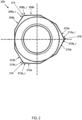
- FIG. 2 shows another embodiment of an improved fastener.
- Fastener 200 may have the same features and components as fastener 100.
- Fastener 200 may include angles at edges 214, 216, 218 that are different than 120 degrees, but fastener 200 may still be driven by standard socket tools, such as a hexagon socket or a 12 point configuration socket.
- the angles at edges 214, 216, 218 of fastener 200 may be 126 to 130 degrees.
- the increased angles at edges 214, 216, 218 of fastener 200 may be caused by recessed regions 208a_r, 208b_r, 210a_r, 210b_r, 212a_r, 212b_r of the torque bearing sides 208a, 208b, 210a, 210b, 212a, 212b adjacent to edges 214, 216, 218, as shown by the space within the dotted line in FIG. 2 .
- the recessed regions 208a_r, 208b_r, 210a_r, 210b_r, 212a_r, 212b_r of the torque bearing sides are disposed inwardly from an imaginary plane defined by the remainder of the torque bearing sides 208a, 208b, 210a, 210b, 212a, 212b.
- the recessed bearing surfaces and increased angle at edges 214, 216, 218 may reduce deformation of the torque bearing surface 208, 210, 212 at edges 214, 216, 218 compared to fastener 100 because the initial contact between a standard socket tool and the recessed regions 208a_r, 208b_r, 210a_r, 210b_r, 212a_r, 212b_r of the torque bearing sides occurs along a generally parallel plane to the initial contact area, which is significantly larger than the initial contact area with fastener 100. As a result, the initial pressure generated by the applied torque is less and may cause less deformation of the fastener 200.
- the recessed bearing surfaces and increased angle at edges 214, 216, 218 are described in U.S. Patent 8,491,247 .
- FIG. 3 shows another embodiment of an improved fastener.
- Fastener 300 may have the same features and components as fasteners 100 and 200.
- Fastener 300 may include modified torque bearing surfaces 308, 310, 312 and modified non-torque bearing surfaces 320, 322, 324, as compared to fasteners 100 and 200.
- Fastener 300 may still be driven by standard socket tools, such as a hexagon socket or a 12 point configuration socket.
- torque bearing surfaces 308, 310, 312 and non-torque bearing surfaces 320, 322, 324 are curved and are smoothly contoured into each other in order to reduce the mass of fastener 300. As shown in FIG.
- the torque bearing surfaces 308, 310, 312 adjacent to non-torque bearing surfaces 320, 322, 324 have been reduced in size such that there is a smooth transition to the non-torque bearing surfaces 320, 322, 324 instead of a sharp corner, as in FIG. 1 .
- non-torque bearing surfaces 320, 322, 324 have been curved to smoothly transition to the torque bearing surfaces 308, 310, 312.
- Fastener 300 may have a reduced mass compared to a standard fastener of similar size due to the modified torque bearing surfaces 308, 310, 312 and modified non-torque bearing surfaces 320, 322, 324.
- the mass reduction of fastener 300 may be approximately 17% compared to a standard fastener of similar size designed for the same application as fastener 300.
- the size reduction and/or curvature of torque bearing surfaces 308, 310, 312 and non-torque bearing surfaces 320, 322, 324 may be adjusted to increase or decrease the mass reduction of fastener 300.
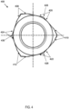
- FIG. 4 shows another embodiment of an improved fastener.
- Fastener 400 may have the same features and components as fasteners 100, 200, and 300. Similar to fastener 300, fastener 400 may include modified torque bearing surfaces 408, 410, 412 and modified non-torque bearing surfaces 420, 422, 424, as compared to fasteners 100 and 200. Fastener 400 may still be driven by standard socket tools, such as a hexagon socket or a 12 point configuration socket. In fastener 400, torque bearing surfaces 408, 410, 412 and non-torque bearing surfaces 420, 422, 424 may be angled toward each other in order to reduce the mass of fastener 400. As shown in FIG.
- the torque bearing surfaces 408, 410, 412 adjacent to non-torque bearing surfaces 420, 422, 424 have been reduced in size and angled such that there is a smooth transition to the non-torque bearing surfaces 420, 422, 424 instead of a sharp corner, as in FIG. 1 .
- non-torque bearing surfaces 420, 422, 424 have been angled to smoothly transition to the torque bearing surfaces 408, 410, 412.
- Non-torque bearing surfaces 420, 422, 424 may include edges 426, 428, 430 as a result of the angles of non-torque bearing surfaces 420, 422, 424.
- Fastener 400 may have a reduced mass compared to a standard fastener of similar size due to the modified torque bearing surfaces 408, 410, 412 and modified non-torque bearing surfaces 420, 422, 424.
- the mass reduction of fastener 400 may be less than the mass reduction of fastener 300 due to the angles of torque bearing surfaces 408, 410, 412 and non-torque bearing surfaces 420, 422, 424.
- the angles of torque bearing surfaces 408, 410, 412 and non-torque bearing surfaces 420, 422, 424 may be adjusted to increase or decrease the mass reduction of fastener 400.
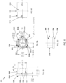
- FIG. 5 shows another embodiment of an improved fastener.
- FIG. 5 includes different views of fastener 500.
- FIG. 5A is a top view of fastener 500.
- FIG. 5B and 5C are side views of fastener 500.
- FIG. 5D is an elevation view of fastener 500.
- Fastener 500 may have the same features and components as fasteners 100, 200, and 300. The dimensions shown in FIG. 5 are exemplary and may be adjusted to meet the design requirements of the application of fastener 500.
- Fastener 500 may include a threaded portion 502 with internal threads with a major diameter 504 shown with a dotted line in FIG. 5A .
- Fastener 500 may include a bearing portion 506 with three torque bearing surfaces 508, 510, 512 that may be designed to receive torque from a tool, such as a socket or wrench, and transmit torque to the threaded portion 502. Similar to fastener 300, fastener 500 may include modified torque bearing surfaces 508, 510, 512 and modified non-torque bearing surfaces 520, 522, 524, as compared to fasteners 100 and 200.
- each torque bearing surface 508, 510, 512 may include two torque bearing sides with an edge 514, 516, 518 between the sides.
- Fastener 500 may be designed and shaped to be driven by standard socket tools, such as a hexagon socket or a 12 point configuration socket. Accordingly, the angle at edges 514, 516, 518 where the torque bearing sides intersect may be approximately 120 degrees to match the angle of a standard hexagon shaped socket. Additionally, the edges 514, 516, 518 may be equally spaced around the longitudinal axis of fastener 500 to match a standard hexagon shaped socket.
- Fastener 500 may have a reduced mass compared to a standard fastener of similar size due to the presence of the non-torque bearing surfaces 520, 522, 524 in place of torque bearing corners that would be located on standard fasteners.
- mass reduction of fastener 500 over an M12 x 1.75 thread x 18.0mm across flats x 12.0mm high standard hexagon nut would be approximately 36%. In grams mass, this is a reduction from 17.5 to 11.1 grams.
- FIG. 5B shows opening 532 extending through the axial length of fastener 500.
- FIG. 5B shows threaded portion 502 with internal threads with a major diameter 504 shown with a dotted line.
- FIGS. 5B and 5C show that fastener 500 may include an abutment portion 534 with an abutment surface 536 designed to make contact with the surface of another component to be fastened, such as a washer or a wheel, depending on the application of fastener 500.
- FIG. 5D shows edges 516, 518 on bearing portion 506.
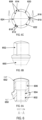
- FIG. 6 shows another embodiment of an improved fastener.
- Fastener 600 includes nut 650 and cap 652.
- Nut 650 may have the same features and components as fasteners 100, 200, and 300.
- Nut 650 may include a threaded portion 602 with internal threads with a major diameter 604 shown with a dotted line in FIG. 6A .
- Nut 650 may include a bearing portion 606 with three torque bearing surfaces 608, 610, 612, as shown in FIG. 6C , that may be designed to receive torque from a tool, such as a socket or wrench, and transmit torque to the threaded portion 602.
- Nut 650 may also include three non-torque bearing surfaces 620, 622, 624.
- the non-torque bearing surfaces 620, 622, 624 may be located adjacent to and between the torque bearing surface 608, 610, 612 such that torque bearing surface 608, 610, 612 are not adjacent to each other. Similar to fastener 300, nut 650 may include modified torque bearing surfaces 608, 610, 612 and modified non-torque bearing surfaces 620, 622, 624, as compared to fasteners 100 and 200.
- Cap 652 may surround the upper portion of nut 650, including bearing portion 606 and the torque bearing surface 608, 610, 612 and the non-torque bearing surfaces 620, 622, 624. Cap 652 may fit tightly around nut 650. Accordingly, cap 652 may include similar torque bearing surfaces and non-torque bearing surfaces. Cap 652 may be crimped around nut 650. Cap 652 and its attachment to nut 650 is described in U.S. Patent Application 14/976,190 .
- fastener 600 may be driven by standard socket tools, such as a hexagon socket or a 12 point configuration socket.
- Fastener 600 may have a reduced mass compared to a standard fastener of similar size due to the presence of the non-torque bearing surfaces 620, 622, 624 in place of torque bearing corners that would be located on standard fasteners.
Landscapes
- Engineering & Computer Science (AREA)
- General Engineering & Computer Science (AREA)
- Mechanical Engineering (AREA)
- Rolling Contact Bearings (AREA)
- Connection Of Plates (AREA)
Claims (14)
- Fixation comprenant une partie filetée ; et une partie portante, la partie portante comprenant :
exactement trois surfaces portantes conçues pour recevoir un couple provenant d'un outil et transmettre un couple à la partie filetée, dans laquelle chaque surface portante comporte deux côtés adjacents dotés d'un bord disposé entre eux, les deux côtés adjacents étant sensiblement planaires et se coupant au niveau du bord selon un angle pour former un point au niveau de chacune des trois surfaces portantes ; et trois surfaces non portantes (320, 322, 324), dans laquelle chacune des trois surfaces non portantes (320, 322, 324) présente une courbe convexe s'étendant de manière continue entre deux des trois surfaces portantes. - Fixation selon la revendication 1, dans laquelle les surfaces portantes sont configurées pour recevoir un couple provenant d'un outil à douille standard et transférer un couple à la partie filetée.
- Fixation selon la revendication 1, dans laquelle chaque bord de la surface portante est disposé à l'opposé de l'une des surfaces non portantes.
- Fixation selon la revendication 1, dans laquelle les côtés adjacents de chaque surface portante sont disposés symétriquement autour du bord de la surface portante.
- Fixation selon la revendication 1, dans laquelle l'un des côtés de chaque surface portante est parallèle à seulement un autre côté d'une autre surface portante.
- Fixation selon la revendication 1, dans laquelle chaque surface portante épouse doucement le contour d'une surface non portante adjacente.
- Fixation selon la revendication 1, dans laquelle les bords des surfaces portantes sont également espacés autour d'un axe longitudinal de la fixation.
- Fixation selon la revendication 1, dans laquelle chaque bord des surfaces portantes est espacé d'environ 120 degrés de chaque autre bord.
- Fixation selon la revendication 1, dans laquelle la partie filetée comprend des filetages internes.
- Fixation selon la revendication 1, dans laquelle la partie filetée comprend des filetages externes.
- Fixation selon la revendication 1, dans laquelle chacun des côtés de chaque surface portante comporte une surface portante en retrait disposée de manière adjacente au bord de la surface portante.
- Fixation selon la revendication 1, comprenant en outre un capuchon disposé autour de la partie portante, dans laquelle le capuchon comprend :
trois surfaces portantes de capuchon conçues pour recevoir un couple provenant d'un outil et transmettre un couple à la partie filetée, dans laquelle chaque surface portante de capuchon comporte deux côtés de capuchon adjacents dotés d'un bord de capuchon disposé entre eux ; et trois surfaces non portantes de capuchon ; dans laquelle une surface non portante de capuchon est disposée entre chacune des surfaces portantes de capuchon, dans laquelle chacune des surfaces portantes de capuchon recouvre l'une des surfaces portantes, et dans laquelle chacune des surfaces non portantes de capuchon recouvre l'une des surfaces non portantes. - Fixation selon la revendication 12, dans laquelle la fixation comprend une partie de bride, le capuchon étant pressé autour de la partie de bride pour retenir le capuchon sur la partie portante sans souder le capuchon.
- Fixation selon la revendication 1, dans laquelle la fixation comprend approximativement 11 pour cent de masse en moins qu'une fixation standard dimensionnée pour la même application.
Applications Claiming Priority (1)
| Application Number | Priority Date | Filing Date | Title |
|---|---|---|---|
| US15/487,805 US10690168B2 (en) | 2017-04-14 | 2017-04-14 | Three-point fastener |
Publications (3)
| Publication Number | Publication Date |
|---|---|
| EP3388694A1 EP3388694A1 (fr) | 2018-10-17 |
| EP3388694C0 EP3388694C0 (fr) | 2024-12-04 |
| EP3388694B1 true EP3388694B1 (fr) | 2024-12-04 |
Family
ID=61906728
Family Applications (1)
| Application Number | Title | Priority Date | Filing Date |
|---|---|---|---|
| EP18165826.1A Active EP3388694B1 (fr) | 2017-04-14 | 2018-04-05 | Fixation à trois points |
Country Status (5)
| Country | Link |
|---|---|
| US (2) | US10690168B2 (fr) |
| EP (1) | EP3388694B1 (fr) |
| JP (1) | JP2018185043A (fr) |
| KR (1) | KR20180116158A (fr) |
| CN (1) | CN108730298B (fr) |
Families Citing this family (4)
| Publication number | Priority date | Publication date | Assignee | Title |
|---|---|---|---|---|
| US10690168B2 (en) | 2017-04-14 | 2020-06-23 | Maclean-Fogg Company | Three-point fastener |
| US11028870B2 (en) | 2018-01-16 | 2021-06-08 | Maclean-Fogg Company | Hybrid three-point drive fastener |
| US20240367306A1 (en) * | 2023-05-01 | 2024-11-07 | Snap-On Incorporated | Tool Handle |
| WO2025104463A1 (fr) * | 2023-11-16 | 2025-05-22 | Howmet Aerospace Inc. | Écrous, éléments de fixation multi-pièces et leurs procédés de fabrication |
Family Cites Families (64)
| Publication number | Priority date | Publication date | Assignee | Title |
|---|---|---|---|---|
| BE433317A (fr) | 1938-03-17 | |||
| US2248696A (en) | 1940-08-03 | 1941-07-08 | Interchem Corp | Method of coloring textile fabrics |
| US3003379A (en) * | 1958-04-24 | 1961-10-10 | Pribitzer Hans | Open end spanner wrench |
| US2969250A (en) | 1959-01-05 | 1961-01-24 | Standard Pressed Steel Co | Socket drive |
| FR1309208A (fr) | 1961-07-29 | 1962-11-16 | Boulon perfectionné par pourtour à crans | |
| US3584667A (en) | 1966-09-19 | 1971-06-15 | Textron Inc | Coupling arrangement and tools for same |
| US3396765A (en) | 1966-10-03 | 1968-08-13 | Gen Motors Corp | Screw and driver |
| US3456548A (en) | 1967-11-22 | 1969-07-22 | Ideal Corp | Screw with hexagonal-collared slotted head |
| US4006660A (en) | 1973-09-08 | 1977-02-08 | Yamamoto Byora Co., Ltd. | Fastener element |
| US3885480A (en) | 1973-12-07 | 1975-05-27 | Res Eng & Mfg | Torque-transmitting arrangement for fasteners and the like |
| FR2321069A1 (fr) * | 1975-08-14 | 1977-03-11 | Cefilac | Accouplement a haute performance |
| FR2361568A1 (fr) | 1976-08-13 | 1978-03-10 | Berner Albert | Vis a tete |
| CA1066542A (fr) | 1977-03-07 | 1979-11-20 | Bernard F. Reiland | Fixation a douille lobulaire pourvue d'une fente |
| US4260005A (en) | 1977-11-09 | 1981-04-07 | Vsi Corporation | Self-locking fastener, fastener system, and process |
| US4361412A (en) * | 1979-12-07 | 1982-11-30 | Gregory Stolarczyk | Fastener with improved torque transfer surfaces |
| US4459074A (en) | 1981-12-15 | 1984-07-10 | Russell, Burdsall & Ward Corporation | Socket drive |
| US4938731A (en) | 1989-02-07 | 1990-07-03 | Barry Wright Corporation | Rotatable, self-aligning lobe coupling |
| US5019080A (en) | 1990-02-13 | 1991-05-28 | Trextron Inc. | Drive system for prosthetic fasteners |
| US5378101A (en) | 1992-12-22 | 1995-01-03 | Textron Inc. | Tamper-proof drive system based upon multi-lobular configuration |
| US5324149A (en) * | 1993-06-16 | 1994-06-28 | Mcgard, Inc. | Lightweight lug nut |
| CN2182295Y (zh) * | 1993-12-04 | 1994-11-09 | 陈军 | 十字通槽螺钉 |
| IT1273374B (it) | 1994-03-04 | 1997-07-08 | Assistenza Tecnica Srl | Vite per serraggi di precisione |
| US5674036A (en) | 1995-12-20 | 1997-10-07 | Hsieh; Chih-Ching | Screw |
| US5628602A (en) * | 1996-01-18 | 1997-05-13 | Kyo-Ei Sangyo Kabushiki Kaisha | Anti-theft hub nut for vehicle wheels |
| US5772377A (en) | 1997-05-08 | 1998-06-30 | Maclean-Fogg Company | Capped wheel fastener |
| DE29709124U1 (de) | 1997-05-23 | 1997-07-24 | Hsieh, Chih-Ching, Fong Yuan, Taichung | Schraube |
| US6269716B1 (en) | 1998-11-18 | 2001-08-07 | Macropore, Inc. | High-torque resorbable screws |
| EP0926362A1 (fr) | 1997-12-16 | 1999-06-30 | Lucent Technologies Inc. | Dispositif à tête d'entraínement multiple et procédé de fabrication |
| ITMI981204A1 (it) | 1998-05-29 | 1999-11-29 | Mauri Flli Srl | Testa per dispositivi rotanti su comando di relativi utensili di manovra con sede interna per l'accoppiamento con gli utensili |
| FR2809781B1 (fr) | 2000-06-06 | 2003-01-03 | Gfi Aerospace | Organe de fixation a empreinte d'extremite dans une partie terminale filetee |
| DE10046562C2 (de) | 2000-09-19 | 2002-11-14 | Eska Saechsische Schraubenwerk | Verfahren zur Herstellung einer Außensechsrundschraube und damit hergestellte Außensechsrundschraube |
| US6655888B2 (en) | 2002-01-16 | 2003-12-02 | Hi-Shear Corporation | Lobed drive for hi-lite fastener |
| US6736580B2 (en) | 2002-01-16 | 2004-05-18 | Hi-Shear Corporation | Lobed drive for hi-lite fastener |
| US20030158555A1 (en) | 2002-02-15 | 2003-08-21 | Roy Sanders | Surgical screw and tool for its insertion |
| GB2390408B (en) | 2002-07-04 | 2005-11-23 | Eric Walker | Screw and driver therefor |
| DE20321249U1 (de) | 2003-05-13 | 2006-09-07 | Richard Bergner Verbindungstechnik Gmbh & Co. Kg | Schraube mit einem gelappten Mehrkantkopf und Werkzeug zum Betätigen einer Schraube mit einem gelappten Mehrkantkopf |
| US7207248B2 (en) | 2003-10-09 | 2007-04-24 | Illinois Tool Works Inc. | Threaded screw fastener characterized by high pull-out resistance, reduced installation torque, and unique head structure and drive socket implement or tool therefor |
| DE102004009788A1 (de) | 2004-02-28 | 2005-09-29 | Daimlerchrysler Ag | Befestigungssystem zur Befestigung von Rädern an Radträgern |
| US7108510B2 (en) | 2004-06-25 | 2006-09-19 | Niznick Gerald A | Endosseous dental implant |
| US7073416B2 (en) | 2004-09-02 | 2006-07-11 | Eazypower Corporation | 3-point/5-point fastener, 3-point/5-point bit |
| US20060062650A1 (en) | 2004-09-20 | 2006-03-23 | The Boeing Company | Hybrid fastener apparatus and method for fastening |
| US7225710B2 (en) | 2005-05-27 | 2007-06-05 | Synthes Gmbh | Combination driver and combination fastener |
| WO2007100906A2 (fr) | 2006-02-28 | 2007-09-07 | Monogram Aerospace Fasteners, Inc. | Attache de boulon aveugle a verrouillage mecanique |
| EP2022992A1 (fr) | 2007-08-10 | 2009-02-11 | Dietmar Houben | Liaison de boulon et d'écrou sans filetage |
| US20090220321A1 (en) | 2008-02-28 | 2009-09-03 | Sakamura Machine Co., Ltd. | Fastening metal fitting |
| JP5658150B2 (ja) | 2008-07-31 | 2015-01-21 | マスリード インコーポレイテッド | 少質量締結具頭部を改良するアセンブリ |
| US8429875B2 (en) | 2009-09-09 | 2013-04-30 | Dameon Bartlett | Concrete foundation form screw and method of use |
| TWM372901U (en) * | 2009-09-18 | 2010-01-21 | Gourmet Equipment Taiwan Corp | Lock element |
| WO2011063099A1 (fr) * | 2009-11-19 | 2011-05-26 | Maclean-Fogg Company | Dispositif de fixation avec surface de support de couple amélioré |
| US8291795B2 (en) | 2010-03-02 | 2012-10-23 | Phillips Screw Company | Fastener system with stable engagement and stick fit |
| DE102011012994A1 (de) | 2011-03-04 | 2012-09-06 | Langmatz Gmbh | Schraube |
| CN103375780B (zh) | 2012-04-26 | 2015-07-29 | 东芝照明技术株式会社 | 螺旋装置以及照明器具 |
| US8997608B2 (en) | 2013-02-14 | 2015-04-07 | ToolTech, LLC | Stud removal tool |
| US9278434B2 (en) | 2013-02-14 | 2016-03-08 | ToolTech, LLC | Socket fastener removal tool |
| US9138873B2 (en) | 2013-02-14 | 2015-09-22 | ToolTech, LLC | Flip socket nut removal tool |
| DE102013105812A1 (de) | 2013-06-05 | 2014-12-11 | Ejot Gmbh & Co. Kg | Schraubenantrieb |
| DE102013021238A1 (de) * | 2013-12-14 | 2015-06-18 | Daimler Ag | Schraubelement mit einem Werkzeugangriff |
| US9957993B2 (en) | 2014-12-17 | 2018-05-01 | Research Engineering & Manufacturing Inc | Recessed head fastener and driver combination |
| US10302119B2 (en) | 2015-02-26 | 2019-05-28 | Cold Heading Company | Lightweight fastener design |
| US10788077B2 (en) | 2015-03-19 | 2020-09-29 | Acument Intellectual Properties, Llc | Drive system with full surface drive contact |
| US10697499B2 (en) | 2015-03-19 | 2020-06-30 | Acument Intellectual Properties, Llc | Drive system with full surface drive contact |
| EP3115153A1 (fr) | 2015-07-07 | 2017-01-11 | IPP Industries Sarl | Outil de vissage et vis correspondante |
| US10195723B2 (en) | 2015-08-18 | 2019-02-05 | Infastech Intellectual Properties Pte. Ltd | Tapered lobular driver and fastener |
| US10690168B2 (en) | 2017-04-14 | 2020-06-23 | Maclean-Fogg Company | Three-point fastener |
-
2017
- 2017-04-14 US US15/487,805 patent/US10690168B2/en active Active
-
2018
- 2018-04-05 EP EP18165826.1A patent/EP3388694B1/fr active Active
- 2018-04-11 CN CN201810318962.XA patent/CN108730298B/zh active Active
- 2018-04-13 KR KR1020180043281A patent/KR20180116158A/ko not_active Ceased
- 2018-04-13 JP JP2018077532A patent/JP2018185043A/ja active Pending
-
2020
- 2020-06-22 US US16/908,140 patent/US20210010504A1/en not_active Abandoned
Also Published As
| Publication number | Publication date |
|---|---|
| EP3388694C0 (fr) | 2024-12-04 |
| EP3388694A1 (fr) | 2018-10-17 |
| CN108730298B (zh) | 2022-02-25 |
| US20210010504A1 (en) | 2021-01-14 |
| US20180298933A1 (en) | 2018-10-18 |
| US10690168B2 (en) | 2020-06-23 |
| CN108730298A (zh) | 2018-11-02 |
| KR20180116158A (ko) | 2018-10-24 |
| JP2018185043A (ja) | 2018-11-22 |
Similar Documents
| Publication | Publication Date | Title |
|---|---|---|
| US4581957A (en) | Tightening tool for nuts or bolts | |
| EP3388694B1 (fr) | Fixation à trois points | |
| US3495485A (en) | Wrench sockets,socket drives and similar couplers | |
| US5358367A (en) | Screw or nut packing micro-adjustment | |
| US5772377A (en) | Capped wheel fastener | |
| US11028870B2 (en) | Hybrid three-point drive fastener | |
| US8491247B2 (en) | Fastener with improved torque bearing surface | |
| US10816024B2 (en) | Lightweight fastener design | |
| US20230083975A1 (en) | Socket drive improvement | |
| US5092203A (en) | Wrench openings | |
| US7270032B1 (en) | Fitting hole of a hand tool | |
| JPH09210038A5 (fr) | ||
| EP3317551B1 (fr) | Vis de serrage ayant un capuchon de limitation de couple | |
| JPH04244612A (ja) | 自動係止ファスナ | |
| US10584735B2 (en) | Pipe clip with tightening screw having torque limiting cap | |
| JP3532180B2 (ja) | シャートルクナット | |
| US20250290581A1 (en) | Clip with clamping screw and torque limiter | |
| JP7652464B1 (ja) | 高トルク伝達ナット及びその締め付け工具 | |
| WO1999002870A1 (fr) | Limiteur de couple | |
| EP3670939A1 (fr) | Dispositif de fixation équipé d'une rondelle rotative | |
| HK40019405A (en) | Socket drive improvement | |
| JP2005188564A (ja) | 多角ボルト |
Legal Events
| Date | Code | Title | Description |
|---|---|---|---|
| PUAI | Public reference made under article 153(3) epc to a published international application that has entered the european phase |
Free format text: ORIGINAL CODE: 0009012 |
|
| STAA | Information on the status of an ep patent application or granted ep patent |
Free format text: STATUS: THE APPLICATION HAS BEEN PUBLISHED |
|
| AK | Designated contracting states |
Kind code of ref document: A1 Designated state(s): AL AT BE BG CH CY CZ DE DK EE ES FI FR GB GR HR HU IE IS IT LI LT LU LV MC MK MT NL NO PL PT RO RS SE SI SK SM TR |
|
| AX | Request for extension of the european patent |
Extension state: BA ME |
|
| STAA | Information on the status of an ep patent application or granted ep patent |
Free format text: STATUS: REQUEST FOR EXAMINATION WAS MADE |
|
| 17P | Request for examination filed |
Effective date: 20190415 |
|
| RBV | Designated contracting states (corrected) |
Designated state(s): AL AT BE BG CH CY CZ DE DK EE ES FI FR GB GR HR HU IE IS IT LI LT LU LV MC MK MT NL NO PL PT RO RS SE SI SK SM TR |
|
| STAA | Information on the status of an ep patent application or granted ep patent |
Free format text: STATUS: EXAMINATION IS IN PROGRESS |
|
| 17Q | First examination report despatched |
Effective date: 20210520 |
|
| GRAP | Despatch of communication of intention to grant a patent |
Free format text: ORIGINAL CODE: EPIDOSNIGR1 |
|
| STAA | Information on the status of an ep patent application or granted ep patent |
Free format text: STATUS: GRANT OF PATENT IS INTENDED |
|
| RIC1 | Information provided on ipc code assigned before grant |
Ipc: F16B 37/14 20060101ALN20230509BHEP Ipc: B60B 3/16 20060101ALI20230509BHEP Ipc: F16B 23/00 20060101AFI20230509BHEP |
|
| INTG | Intention to grant announced |
Effective date: 20230605 |
|
| GRAJ | Information related to disapproval of communication of intention to grant by the applicant or resumption of examination proceedings by the epo deleted |
Free format text: ORIGINAL CODE: EPIDOSDIGR1 |
|
| STAA | Information on the status of an ep patent application or granted ep patent |
Free format text: STATUS: EXAMINATION IS IN PROGRESS |
|
| INTC | Intention to grant announced (deleted) | ||
| RIC1 | Information provided on ipc code assigned before grant |
Ipc: F16B 37/14 20060101ALN20231016BHEP Ipc: B60B 3/16 20060101ALI20231016BHEP Ipc: F16B 23/00 20060101AFI20231016BHEP |
|
| GRAP | Despatch of communication of intention to grant a patent |
Free format text: ORIGINAL CODE: EPIDOSNIGR1 |
|
| STAA | Information on the status of an ep patent application or granted ep patent |
Free format text: STATUS: GRANT OF PATENT IS INTENDED |
|
| RIC1 | Information provided on ipc code assigned before grant |
Ipc: F16B 37/14 20060101ALN20231109BHEP Ipc: B60B 3/16 20060101ALI20231109BHEP Ipc: F16B 23/00 20060101AFI20231109BHEP |
|
| INTG | Intention to grant announced |
Effective date: 20231128 |
|
| GRAS | Grant fee paid |
Free format text: ORIGINAL CODE: EPIDOSNIGR3 |
|
| GRAA | (expected) grant |
Free format text: ORIGINAL CODE: 0009210 |
|
| STAA | Information on the status of an ep patent application or granted ep patent |
Free format text: STATUS: THE PATENT HAS BEEN GRANTED |
|
| AK | Designated contracting states |
Kind code of ref document: B1 Designated state(s): AL AT BE BG CH CY CZ DE DK EE ES FI FR GB GR HR HU IE IS IT LI LT LU LV MC MK MT NL NO PL PT RO RS SE SI SK SM TR |
|
| REG | Reference to a national code |
Ref country code: GB Ref legal event code: FG4D |
|
| REG | Reference to a national code |
Ref country code: CH Ref legal event code: EP |
|
| REG | Reference to a national code |
Ref country code: DE Ref legal event code: R096 Ref document number: 602018077166 Country of ref document: DE |
|
| REG | Reference to a national code |
Ref country code: IE Ref legal event code: FG4D |
|
| U01 | Request for unitary effect filed |
Effective date: 20241217 |
|
| U07 | Unitary effect registered |
Designated state(s): AT BE BG DE DK EE FI FR IT LT LU LV MT NL PT RO SE SI Effective date: 20250110 |
|
| PG25 | Lapsed in a contracting state [announced via postgrant information from national office to epo] |
Ref country code: HR Free format text: LAPSE BECAUSE OF FAILURE TO SUBMIT A TRANSLATION OF THE DESCRIPTION OR TO PAY THE FEE WITHIN THE PRESCRIBED TIME-LIMIT Effective date: 20241204 |
|
| PG25 | Lapsed in a contracting state [announced via postgrant information from national office to epo] |
Ref country code: ES Free format text: LAPSE BECAUSE OF FAILURE TO SUBMIT A TRANSLATION OF THE DESCRIPTION OR TO PAY THE FEE WITHIN THE PRESCRIBED TIME-LIMIT Effective date: 20241204 |
|
| PG25 | Lapsed in a contracting state [announced via postgrant information from national office to epo] |
Ref country code: NO Free format text: LAPSE BECAUSE OF FAILURE TO SUBMIT A TRANSLATION OF THE DESCRIPTION OR TO PAY THE FEE WITHIN THE PRESCRIBED TIME-LIMIT Effective date: 20250304 |
|
| PG25 | Lapsed in a contracting state [announced via postgrant information from national office to epo] |
Ref country code: GR Free format text: LAPSE BECAUSE OF FAILURE TO SUBMIT A TRANSLATION OF THE DESCRIPTION OR TO PAY THE FEE WITHIN THE PRESCRIBED TIME-LIMIT Effective date: 20250305 |
|
| PG25 | Lapsed in a contracting state [announced via postgrant information from national office to epo] |
Ref country code: RS Free format text: LAPSE BECAUSE OF FAILURE TO SUBMIT A TRANSLATION OF THE DESCRIPTION OR TO PAY THE FEE WITHIN THE PRESCRIBED TIME-LIMIT Effective date: 20250304 |
|
| U20 | Renewal fee for the european patent with unitary effect paid |
Year of fee payment: 8 Effective date: 20250428 |
|
| PG25 | Lapsed in a contracting state [announced via postgrant information from national office to epo] |
Ref country code: SM Free format text: LAPSE BECAUSE OF FAILURE TO SUBMIT A TRANSLATION OF THE DESCRIPTION OR TO PAY THE FEE WITHIN THE PRESCRIBED TIME-LIMIT Effective date: 20241204 |
|
| PG25 | Lapsed in a contracting state [announced via postgrant information from national office to epo] |
Ref country code: PL Free format text: LAPSE BECAUSE OF FAILURE TO SUBMIT A TRANSLATION OF THE DESCRIPTION OR TO PAY THE FEE WITHIN THE PRESCRIBED TIME-LIMIT Effective date: 20241204 |
|
| PGFP | Annual fee paid to national office [announced via postgrant information from national office to epo] |
Ref country code: GB Payment date: 20250428 Year of fee payment: 8 |
|
| PG25 | Lapsed in a contracting state [announced via postgrant information from national office to epo] |
Ref country code: IS Free format text: LAPSE BECAUSE OF FAILURE TO SUBMIT A TRANSLATION OF THE DESCRIPTION OR TO PAY THE FEE WITHIN THE PRESCRIBED TIME-LIMIT Effective date: 20250404 |
|
| PG25 | Lapsed in a contracting state [announced via postgrant information from national office to epo] |
Ref country code: SK Free format text: LAPSE BECAUSE OF FAILURE TO SUBMIT A TRANSLATION OF THE DESCRIPTION OR TO PAY THE FEE WITHIN THE PRESCRIBED TIME-LIMIT Effective date: 20241204 |
|
| PG25 | Lapsed in a contracting state [announced via postgrant information from national office to epo] |
Ref country code: CZ Free format text: LAPSE BECAUSE OF FAILURE TO SUBMIT A TRANSLATION OF THE DESCRIPTION OR TO PAY THE FEE WITHIN THE PRESCRIBED TIME-LIMIT Effective date: 20241204 |
|
| PLBE | No opposition filed within time limit |
Free format text: ORIGINAL CODE: 0009261 |
|
| STAA | Information on the status of an ep patent application or granted ep patent |
Free format text: STATUS: NO OPPOSITION FILED WITHIN TIME LIMIT |
|
| REG | Reference to a national code |
Ref country code: CH Ref legal event code: L10 Free format text: ST27 STATUS EVENT CODE: U-0-0-L10-L00 (AS PROVIDED BY THE NATIONAL OFFICE) Effective date: 20251015 |
|
| 26N | No opposition filed |
Effective date: 20250905 |
|
| REG | Reference to a national code |
Ref country code: CH Ref legal event code: H13 Free format text: ST27 STATUS EVENT CODE: U-0-0-H10-H13 (AS PROVIDED BY THE NATIONAL OFFICE) Effective date: 20251125 |
|
| PG25 | Lapsed in a contracting state [announced via postgrant information from national office to epo] |
Ref country code: MC Free format text: LAPSE BECAUSE OF FAILURE TO SUBMIT A TRANSLATION OF THE DESCRIPTION OR TO PAY THE FEE WITHIN THE PRESCRIBED TIME-LIMIT Effective date: 20241204 |
|
| PG25 | Lapsed in a contracting state [announced via postgrant information from national office to epo] |
Ref country code: CH Free format text: LAPSE BECAUSE OF NON-PAYMENT OF DUE FEES Effective date: 20250430 |