EP3317546B1 - Fluidic component - Google Patents
Fluidic component Download PDFInfo
- Publication number
- EP3317546B1 EP3317546B1 EP16798135.6A EP16798135A EP3317546B1 EP 3317546 B1 EP3317546 B1 EP 3317546B1 EP 16798135 A EP16798135 A EP 16798135A EP 3317546 B1 EP3317546 B1 EP 3317546B1
- Authority
- EP
- European Patent Office
- Prior art keywords
- component
- outlet
- flow
- outlet opening
- fluidic component
- Prior art date
- Legal status (The legal status is an assumption and is not a legal conclusion. Google has not performed a legal analysis and makes no representation as to the accuracy of the status listed.)
- Active
Links
- 239000012530 fluid Substances 0.000 claims description 221
- 230000010355 oscillation Effects 0.000 claims description 41
- 238000004140 cleaning Methods 0.000 claims description 16
- 238000011144 upstream manufacturing Methods 0.000 claims description 9
- 230000007423 decrease Effects 0.000 claims description 8
- 238000002485 combustion reaction Methods 0.000 claims description 3
- 238000002347 injection Methods 0.000 claims description 3
- 239000007924 injection Substances 0.000 claims description 3
- 238000005406 washing Methods 0.000 claims description 3
- 239000000446 fuel Substances 0.000 claims description 2
- 230000008859 change Effects 0.000 description 15
- XLYOFNOQVPJJNP-UHFFFAOYSA-N water Substances O XLYOFNOQVPJJNP-UHFFFAOYSA-N 0.000 description 8
- 238000007373 indentation Methods 0.000 description 7
- 230000009172 bursting Effects 0.000 description 4
- 238000009826 distribution Methods 0.000 description 4
- 230000000694 effects Effects 0.000 description 4
- 239000007788 liquid Substances 0.000 description 4
- 238000004519 manufacturing process Methods 0.000 description 4
- 230000007246 mechanism Effects 0.000 description 4
- 230000007704 transition Effects 0.000 description 4
- 238000005520 cutting process Methods 0.000 description 3
- 230000009467 reduction Effects 0.000 description 3
- 239000007921 spray Substances 0.000 description 3
- 238000009827 uniform distribution Methods 0.000 description 3
- 230000015572 biosynthetic process Effects 0.000 description 2
- 230000003247 decreasing effect Effects 0.000 description 2
- 238000012423 maintenance Methods 0.000 description 2
- 238000000926 separation method Methods 0.000 description 2
- 238000004088 simulation Methods 0.000 description 2
- 235000008733 Citrus aurantifolia Nutrition 0.000 description 1
- 241000589248 Legionella Species 0.000 description 1
- 208000007764 Legionnaires' Disease Diseases 0.000 description 1
- 235000011941 Tilia x europaea Nutrition 0.000 description 1
- 238000005266 casting Methods 0.000 description 1
- 230000003111 delayed effect Effects 0.000 description 1
- 239000013013 elastic material Substances 0.000 description 1
- 230000001771 impaired effect Effects 0.000 description 1
- 230000003993 interaction Effects 0.000 description 1
- 239000004571 lime Substances 0.000 description 1
- 238000000034 method Methods 0.000 description 1
- 244000052769 pathogen Species 0.000 description 1
- 230000002093 peripheral effect Effects 0.000 description 1
- 230000008569 process Effects 0.000 description 1
- 230000000717 retained effect Effects 0.000 description 1
- 230000002441 reversible effect Effects 0.000 description 1
- 239000011265 semifinished product Substances 0.000 description 1
- 238000005245 sintering Methods 0.000 description 1
- 239000000344 soap Substances 0.000 description 1
- 239000007787 solid Substances 0.000 description 1
- 230000000087 stabilizing effect Effects 0.000 description 1
- 239000000126 substance Substances 0.000 description 1
- 239000000758 substrate Substances 0.000 description 1
- 230000001052 transient effect Effects 0.000 description 1
- 238000009736 wetting Methods 0.000 description 1
Images


Classifications
-
- B—PERFORMING OPERATIONS; TRANSPORTING
- B05—SPRAYING OR ATOMISING IN GENERAL; APPLYING FLUENT MATERIALS TO SURFACES, IN GENERAL
- B05B—SPRAYING APPARATUS; ATOMISING APPARATUS; NOZZLES
- B05B1/00—Nozzles, spray heads or other outlets, with or without auxiliary devices such as valves, heating means
- B05B1/02—Nozzles, spray heads or other outlets, with or without auxiliary devices such as valves, heating means designed to produce a jet, spray, or other discharge of particular shape or nature, e.g. in single drops, or having an outlet of particular shape
- B05B1/08—Nozzles, spray heads or other outlets, with or without auxiliary devices such as valves, heating means designed to produce a jet, spray, or other discharge of particular shape or nature, e.g. in single drops, or having an outlet of particular shape of pulsating nature, e.g. delivering liquid in successive separate quantities ; Fluidic oscillators
-
- B—PERFORMING OPERATIONS; TRANSPORTING
- B05—SPRAYING OR ATOMISING IN GENERAL; APPLYING FLUENT MATERIALS TO SURFACES, IN GENERAL
- B05B—SPRAYING APPARATUS; ATOMISING APPARATUS; NOZZLES
- B05B1/00—Nozzles, spray heads or other outlets, with or without auxiliary devices such as valves, heating means
- B05B1/34—Nozzles, spray heads or other outlets, with or without auxiliary devices such as valves, heating means designed to influence the nature of flow of the liquid or other fluent material, e.g. to produce swirl
-
- B—PERFORMING OPERATIONS; TRANSPORTING
- B05—SPRAYING OR ATOMISING IN GENERAL; APPLYING FLUENT MATERIALS TO SURFACES, IN GENERAL
- B05B—SPRAYING APPARATUS; ATOMISING APPARATUS; NOZZLES
- B05B1/00—Nozzles, spray heads or other outlets, with or without auxiliary devices such as valves, heating means
- B05B1/02—Nozzles, spray heads or other outlets, with or without auxiliary devices such as valves, heating means designed to produce a jet, spray, or other discharge of particular shape or nature, e.g. in single drops, or having an outlet of particular shape
-
- B—PERFORMING OPERATIONS; TRANSPORTING
- B05—SPRAYING OR ATOMISING IN GENERAL; APPLYING FLUENT MATERIALS TO SURFACES, IN GENERAL
- B05B—SPRAYING APPARATUS; ATOMISING APPARATUS; NOZZLES
- B05B7/00—Spraying apparatus for discharge of liquids or other fluent materials from two or more sources, e.g. of liquid and air, of powder and gas
- B05B7/02—Spray pistols; Apparatus for discharge
- B05B7/04—Spray pistols; Apparatus for discharge with arrangements for mixing liquids or other fluent materials before discharge
-
- B—PERFORMING OPERATIONS; TRANSPORTING
- B08—CLEANING
- B08B—CLEANING IN GENERAL; PREVENTION OF FOULING IN GENERAL
- B08B3/00—Cleaning by methods involving the use or presence of liquid or steam
- B08B3/02—Cleaning by the force of jets or sprays
-
- F—MECHANICAL ENGINEERING; LIGHTING; HEATING; WEAPONS; BLASTING
- F02—COMBUSTION ENGINES; HOT-GAS OR COMBUSTION-PRODUCT ENGINE PLANTS
- F02M—SUPPLYING COMBUSTION ENGINES IN GENERAL WITH COMBUSTIBLE MIXTURES OR CONSTITUENTS THEREOF
- F02M61/00—Fuel-injectors not provided for in groups F02M39/00 - F02M57/00 or F02M67/00
- F02M61/16—Details not provided for in, or of interest apart from, the apparatus of groups F02M61/02 - F02M61/14
- F02M61/18—Injection nozzles, e.g. having valve seats; Details of valve member seated ends, not otherwise provided for
- F02M61/1806—Injection nozzles, e.g. having valve seats; Details of valve member seated ends, not otherwise provided for characterised by the arrangement of discharge orifices, e.g. orientation or size
- F02M61/1846—Dimensional characteristics of discharge orifices
-
- F—MECHANICAL ENGINEERING; LIGHTING; HEATING; WEAPONS; BLASTING
- F15—FLUID-PRESSURE ACTUATORS; HYDRAULICS OR PNEUMATICS IN GENERAL
- F15B—SYSTEMS ACTING BY MEANS OF FLUIDS IN GENERAL; FLUID-PRESSURE ACTUATORS, e.g. SERVOMOTORS; DETAILS OF FLUID-PRESSURE SYSTEMS, NOT OTHERWISE PROVIDED FOR
- F15B21/00—Common features of fluid actuator systems; Fluid-pressure actuator systems or details thereof, not covered by any other group of this subclass
- F15B21/12—Fluid oscillators or pulse generators
-
- B—PERFORMING OPERATIONS; TRANSPORTING
- B05—SPRAYING OR ATOMISING IN GENERAL; APPLYING FLUENT MATERIALS TO SURFACES, IN GENERAL
- B05B—SPRAYING APPARATUS; ATOMISING APPARATUS; NOZZLES
- B05B1/00—Nozzles, spray heads or other outlets, with or without auxiliary devices such as valves, heating means
- B05B1/02—Nozzles, spray heads or other outlets, with or without auxiliary devices such as valves, heating means designed to produce a jet, spray, or other discharge of particular shape or nature, e.g. in single drops, or having an outlet of particular shape
- B05B1/10—Nozzles, spray heads or other outlets, with or without auxiliary devices such as valves, heating means designed to produce a jet, spray, or other discharge of particular shape or nature, e.g. in single drops, or having an outlet of particular shape in the form of a fine jet, e.g. for use in wind-screen washers
Definitions
- the invention relates to a fluidic component according to the preamble of claim 1 and to a cleaning device which comprises such a fluidic component.
- the fluidic component is provided for generating a moving fluid jet.
- Exemplary fluidic components are, for example, from US 2013/240644 A1 , EP 1 472 966 A2 , US 2007/295840 A1 and US 2004/251315 A1 known.
- nozzles For generating a fluid jet at high speed or high impulse, nozzles are known from the prior art which are designed to apply a pressure to the fluid jet which is higher than the ambient pressure.
- the fluid is accelerated and / or directed or bundled by means of the nozzle.
- the nozzle In order to generate a movement of a fluid jet, the nozzle is usually moved by means of a device.
- an additional device is required in addition to the nozzle. This additional device includes moving components that can easily wear out. The costs associated with production and maintenance are correspondingly high.
- Another disadvantage is that, due to the movable components, a relatively large overall space is required.
- Fluidic components are also known for generating a movable fluid flow (or fluid jet).
- the fluidic components do not include any movable components that are used to generate a movable fluid flow.
- a strong pressure gradient occurs regularly, so that cavitation, i.e. the formation of cavities (bubbles), can occur when a liquid fluid flow flows through the fluidic components. This can massively reduce the service life of the components or cause the fluidic components to fail.
- the known fluidic components are also more suitable for wetting surfaces than for generating a fluid jet at high speed or with high momentum. For example, a fluid flow emerging from a known fluidic component has the spray characteristics of a flat jet nozzle which generates a finely atomized jet.
- the present invention is based on the object of creating a fluidic component that is designed to provide a moving fluid jet at high speed or high pressure, the fluidic component having a high level of failure safety and correspondingly lower maintenance costs.
- the fluidic component comprises a flow chamber through which a fluid flow can flow.
- the fluid flow can be a liquid flow or a gas flow.
- the flow chamber comprises an inlet opening and an outlet opening through which the fluid flow enters the flow chamber or exits the flow chamber again.
- the fluidic component further comprises at least one means for the targeted change of direction of the fluid flow at the outlet opening, the means being designed in particular to form a spatial oscillation of the fluid flow at the outlet opening.
- the flow chamber has a main flow channel which connects the inlet opening and the outlet opening to one another, and at least one secondary flow channel as the at least one means for the targeted change in direction of the fluid flow at the outlet opening.
- the fluidic component is characterized in that the inlet opening has a larger cross-sectional area than the outlet opening or that the inlet opening and the outlet opening have the same cross-sectional area.
- the cross-sectional areas of the inlet opening and the outlet opening are to be understood to mean the smallest cross-sectional areas of the fluidic component that the fluid flow passes when it enters the flow chamber or exits the flow chamber again.
- Movable components for generating an oscillating beam can be dispensed with in the arrangement according to the invention, so that costs and expenditures caused by this do not arise.
- the development of vibration and noise in the fluidic component according to the invention is relatively low.
- the spatially oscillating fluid jet which emerges from the fluidic component according to the invention has a high removal and cleaning capacity due to its compactness and high speed when it is directed onto a surface.
- the fluidic component according to the invention can therefore be used, for example, in cleaning technology.
- the fluidic component according to the invention is also of interest for mixing technology (in which two or more different fluids are to be mixed with one another) and production technology (for example water jet cutting). For example, the effectiveness of water jet cutting can be increased with a pulsating fluid jet emerging from the fluidic component according to the invention.
- the cross-sectional area of the inlet opening can be the same size as or larger than the cross-sectional area of the outlet opening.
- the size ratio can be selected depending on the desired characteristics (speed or pulse, compactness, oscillation frequency) of the emerging beam. However, other parameters, such as the size (for example the volume and / or the component depth, component width, component length) of the fluidic component, the shape of the fluidic component, the type of fluid (gas, liquid with low viscosity, liquid with high Viscosity), the size of the pressure with which the fluid flow enters the fluidic component, the input speed of the fluid and the volume flow influence the choice of the size ratio.
- the oscillation frequency can be between 0.5 Hz and 30 kHz.
- a preferred frequency range is between 3 Hz and 400 Hz.
- the inlet pressure can be between 0.01 bar and 6000 bar above ambient pressure.
- the inlet pressure is typically between 0.01 bar and 12 bar above the ambient pressure.
- high pressure applications such as cleaning (of vehicles, semi-finished products, machines or stables) or the mixing of two different fluids, the inlet pressure is typically between 5 bar and 300 bar.
- the cross-sectional area of the inlet opening can be larger by a factor of up to 2.5 than the cross-sectional area of the outlet opening. According to a particularly preferred embodiment, the cross-sectional area of the inlet opening can be a factor of up to 1.5 larger than the cross-sectional area of the outlet opening.
- the cross-sectional area of the outlet opening can have any shape, such as square, rectangular, polygonal, round, oval, etc., for example. The same applies to the cross-sectional area of the inlet opening.
- the shape of the inlet opening can correspond to the shape of the outlet opening or differ from the latter.
- a round cross-sectional area of the outlet opening can be selected, for example, in order to generate a particularly compact / bundled fluid jet. Such a fluid jet can be used in particular in high-pressure cleaning technology or in water jet cutting.
- both the inlet opening and the outlet opening have a rectangular cross section.
- the inlet opening can have a greater width than the outlet opening.
- the width of the inlet and outlet opening is defined in relation to the geometry of the fluidic component.
- the fluidic component can, for example, be essentially cuboid and accordingly have a component length, a component width and a component depth, the component length determining the distance between the inlet opening and the outlet opening and the component width and the component depth being defined perpendicular to each other and to the component length and where the component width is greater than the component depth.
- the component length thus extends essentially parallel to the main direction of propagation of the fluid flow, which is intended to move from the inlet opening to the outlet opening. If the inlet and outlet openings lie on an axis that extends parallel to the component length, the distance between the inlet and outlet openings corresponds to the component length.
- the inlet and outlet openings are arranged offset from one another, said opening extends If the axis is at an angle not equal to 0 ° to the component length, the component length and the offset of the inlet and outlet openings determine the distance between the inlet and outlet openings along the axis.
- the ratio of component length to component width can be 1/3 to 5. The ratio is preferably in the range from 1/1 to 4/1.
- the component width can be in the range between 0.15 mm and 2.5 m. In a preferred embodiment, the component width is between 1.5 mm and 200 mm. The dimensions mentioned depend in particular on the application for which the fluidic component is to be used.
- a substantially cuboid fluidic component can have a rectangular outlet opening with a width that corresponds to 1/3 to 1/50 of the component width, and a rectangular inlet opening with a width that corresponds to 1/3 to 1/20 of the component width.
- the width of the outlet opening can correspond to 1/5 to 1/15 of the component width and the width of the inlet opening 1/5 to 1/10 of the component width.
- the ratio of the component depth to the width of the inlet opening can be 1/20 to 5. This ratio is also known as the aspect ratio.
- a preferred aspect ratio is between 1/6 and 2.
- the size ratios mentioned also depend in particular on the application for which the fluidic component is to be used.
- the fluidic component has a component depth that is constant over the entire component length.
- the component depth can decrease (steadily (with or without constant increase) or abruptly) from the inlet opening towards the outlet opening. Due to the decreasing component depth, the fluid jet is pre-bundled within the fluidic component, so that a compact fluid jet emerges from the fluidic component. A widening or bursting of the fluid jet can thus be delayed and thus does not take place directly at the outlet opening, but only further downstream. This measure is advantageous, for example, in cleaning technology or in water jet technology.
- the component depth can increase from the inlet opening to the outlet opening, the component width decreasing such that the cross-sectional area of the outlet opening is smaller than or equal to the cross-sectional area of the inlet opening.
- the flow chamber has at least one secondary flow channel as a means for the targeted change in direction of the fluid flow at the outlet opening.
- the secondary flow channel can be flowed through by part of the fluid flow, the secondary flow.
- the part of the fluid flow which does not enter the secondary flow channel but exits the fluidic component is referred to as the main flow.
- the at least one bypass duct can have an inlet that is located in the vicinity of the outlet opening and an outlet that is located in the vicinity of the inlet opening.
- the at least one secondary flow channel can be arranged next to (not behind or in front of) the main flow channel when viewed in the fluid flow direction (from the inlet opening to the outlet opening).
- two secondary flow channels can be provided which (viewed in the main flow direction) extend laterally next to the main flow channel, the main flow channel being arranged between the two secondary flow channels.
- the secondary flow channels and the main flow channel are arranged in a row along the width of the component and each extend along the length of the component.
- the secondary flow ducts and the main flow duct can be arranged in a row along the component depth and each extend along the component length.
- the at least one secondary flow channel is preferably separated from the main flow channel by a block.
- This block can have different shapes.
- the cross section of the block can taper in the direction of the fluid flow (from the inlet opening to the outlet opening).
- the cross section of the block can taper or increase in the middle between its end facing the inlet opening and its end facing the outlet opening. It is also possible to enlarge the cross section of the block as the distance from the inlet opening increases.
- the block can have rounded edges. Sharp edges can be provided on the block in particular in the vicinity of the inlet opening and / or the outlet opening.
- the at least one secondary flow channel can have a greater or smaller depth than the main flow channel.
- the oscillation frequency of the exiting fluid jet can also be influenced.
- the oscillation frequency drops if the other parameters remain essentially unchanged.
- the oscillation frequency increases accordingly if the component depth in the area of the at least one secondary flow channel is increased (compared to the main flow channel) and the other parameters remain essentially unchanged.
- a separator is to be understood as an element projecting into the flow chamber (transversely to the flow direction prevailing in the bypass duct) at the inlet of the at least one bypass duct.
- the separator can be provided as a deformation (in particular an indentation) of the secondary flow duct wall or as a projection formed in some other way.
- the separator (circle) can be conical or pyramidal. The use of such a separator makes it possible not only to influence the oscillation frequency but also to vary the so-called oscillation angle.
- the angle of oscillation is the angle that the oscillating fluid jet sweeps (between its two maximum deflections). If several secondary flow channels are provided, a separator can be provided for each of the secondary flow channels or only for some of the secondary flow channels.
- an outlet channel can be provided directly upstream of the outlet opening.
- the outlet channel can have a cross-sectional shape which is constant over the entire length of the outlet channel and which corresponds to the shape of the cross-sectional area of the outlet opening (square, rectangular, polygonal, round, etc.).
- the shape of the cross-sectional area of the outlet channel can change over the length of the outlet channel.
- the size of the cross-sectional area of the outlet opening can remain constant (that is then also the size of the outlet opening) or change. In particular, the size of the cross-sectional area of the outlet channel in the fluid flow direction from the inlet opening to the outlet opening can be reduced.
- the shape and / or size of the cross-sectional area of the main flow channel can change from the inlet opening to the outlet opening.
- the shape of the cross-sectional area (of the outlet channel or of the main flow channel) can change from rectangular to round (in the fluid flow direction from the inlet opening to the outlet opening).
- the fluid jet can already be pre-bundled in the fluidic component, so that the compactness of the exiting fluid jet can be increased.
- the size of the cross-sectional area of the outlet channel can change, in particular decrease in the fluid flow direction from the inlet opening to the outlet opening.
- the shape of the outlet channel influences the angle of oscillation of the exiting fluid jet and can be selected so that a desired angle of oscillation is established.
- the outlet channel can be designed as a further feature to be straight or curved.
- the parameters of the fluidic component can be set in a variety of ways. These parameters are preferably selected in such a way that the pressure with which the fluid flow is acted upon and enters the fluidic component via the inlet opening is substantially reduced at the outlet opening. A slight pressure reduction that occurs at the outlet opening can already take place in the fluidic component (upstream of the outlet opening).
- the fluidic component has two or more outlet openings. These outlet openings can be formed by arranging a flow divider immediately upstream of the outlet openings.
- the flow divider is a means for splitting the fluid flow into two or more sub-flows.
- each outlet opening can each have a smaller cross-sectional area than the inlet opening or all outlet openings and the inlet opening can each have an equally large cross-sectional area.
- only one of the two / more outlet openings can also have a smaller / equal cross-sectional area than / like the inlet opening.
- a fluidic component with two or more outlet openings is suitable for generating two or more fluid jets which emerge from the fluidic component in a pulsating manner over time. A (minimal) local oscillation can occur within a pulse.
- the flow divider can have different shapes, but they all have in common that they widen downstream in the plane in which the exiting fluid jet oscillates and transversely to the longitudinal axis of the fluidic component.
- the flow divider can be arranged in the outlet channel (if present).
- the flow divider can extend deeper into the fluidic component, for example into the main flow channel.
- the flow divider can be arranged symmetrically (with respect to an axis that extends parallel to the component length) in such a way that the outlet openings are identical in shape and size.
- other positions are also possible, which can be selected as a function of the desired pulse characteristics of the exiting fluid jets.
- the fluidic component comprises a fluid flow guide which is arranged downstream in connection with the outlet opening.
- the fluid flow guide is essentially tubular (for example with a constant large cross-sectional area and constant cross-sectional area shape) and is movable by the fluid flow changing its direction.
- the cross-sectional area of the fluid flow guide can correspond to the cross-sectional area of the outlet opening.
- the movement of the fluid flow guide has no influence on the direction of the exiting fluid flow.
- the fluid flow guide merely represents a means (passive component) for the additional bundling of the oscillating exiting fluid jet.
- the fluid flow bundled in this way fans out or bursts further downstream than a fluid flow emerging from a fluid component without fluid flow guide. This property can be particularly desirable in cleaning technology.
- a bearing can be provided, for example, via which the fluid flow guide is movably attached to the outlet opening.
- Different joint designs are known from practice, which can be used in principle.
- a ball joint or a solid body joint is possible.
- the fluid flow guide and / or the mounting can be made of an elastic material.
- the cross-sectional area of the outlet opening of the fluid flow guide can also be implemented differently.
- the outlet opening of the fluid flow guide is the opening from which the fluid flow exits from the fluid flow guide (and thus from the fluidic component). Shapes for the cross-sectional area of the outlet opening of the fluid flow guide, which were described in connection with the outlet opening of the fluidic component without a fluid flow guide, are thus possible.
- the shape of the cross-sectional area of the fluid flow guide can also change over the length of the fluid flow guide.
- a rectangular cross-sectional area can be provided in the area of the bearing (that is to say at the inlet of the fluid flow guide), which merges into a round cross-sectional area downstream.
- the fluidic component has an outlet widening which adjoins the outlet opening downstream of the outlet opening.
- the outlet widening connects directly (directly) to the outlet opening downstream of the outlet opening.
- the outlet widening can, for example, be funnel-shaped.
- the outlet widening can have a cross-sectional area (perpendicular to the fluid flow direction) have, the size of which increases from the outlet opening downstream.
- the outlet opening can form the point with the smallest cross-sectional area between the flow chamber and the outlet widening.
- the outlet widening can serve to bundle a fluid jet which experiences a high pressure reduction at the outlet opening and thus bursts open at the outlet opening.
- the outlet widening can thus (at least partially) counteract the bursting of the fluid jet.
- the outlet widening can have a width which increases (steadily) downstream from the outlet opening.
- the width is that extension of the outlet widening that lies in the plane in which the exiting fluid flow oscillates.
- the depth of the outlet expansion can be constant.
- the depth of the outlet widening is that extension of the outlet widening which is directed substantially perpendicular to the plane in which the exiting fluid flow oscillates.
- the depth of the outlet widening can increase or decrease downstream (compared to the component depth that is present at the outlet opening).
- a further focusing of the exiting fluid jet can be achieved by reducing the component depth in the area of the outlet widening in a downstream direction.
- the outlet widening can be delimited by a wall which encloses an angle in the plane in which the exiting fluid jet oscillates within an oscillation angle, the angle of the outlet widening by 0 ° to 15 °, preferably by 0 ° to 10 °, is larger than the oscillation angle.
- the outlet widening thus does not affect the size of the oscillation angle, but only the bursting of the exiting fluid jet.
- This angular size is useful, for example, for fluidic components that produce a uniform distribution of the fluid on the surface to be sprayed without widening the outlet.
- the angle of the outlet widening can also be selected to be smaller than the oscillation angle, for example if the fluidic component without the outlet widening produces an uneven distribution of the fluid on the surface to be sprayed or if the oscillation angle is to be reduced.
- An outlet channel can be provided upstream of the outlet opening, the delimiting walls of which enclose an angle in the plane in which the exiting fluid jet oscillates, wherein the angle of the outlet channel can be greater than the oscillation angle and also greater than the angle of the outlet widening.
- the angle of the The outlet channel is preferably at least 1.1 times larger than the angle of the outlet widening. According to a particularly preferred embodiment, the angle of the outlet channel lies in a range which extends from 1.1 times the angle of the outlet expansion to 3.5 times the angle of the outlet expansion.
- the invention also relates to an injection system and a cleaning device, each of which includes the fluidic component according to the invention.
- the injection system is provided for injecting a fuel into an internal combustion engine, such as an internal combustion engine or a gas turbine, which is used, for example, in motor vehicles.
- the cleaning device is in particular a dishwasher, a washing machine, an industrial cleaning system or a high-pressure cleaner.
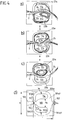
- a fluidic component 1 according to an embodiment of the invention is shown schematically.
- the Figures 2 and 3 show a sectional view of this fluidic component 1 along the lines A'-A "and B'-B".
- the fluidic component 1 comprises a flow chamber 10 through which a fluid flow 2 can flow ( Figure 4 ).
- the flow chamber 10 is also referred to as an interaction chamber.
- the flow chamber 10 comprises an inlet opening 101 via which the fluid flow 2 enters the flow chamber 10, and an outlet opening 102 via which the fluid flow 2 exits the flow chamber 10.
- the inlet opening 101 and the outlet opening 102 are arranged on two opposite sides of the fluidic component 1.
- the fluid flow 2 moves in the flow chamber 10 essentially along a longitudinal axis A of the fluidic component 1 (which connects the inlet opening 101 and the outlet opening 102 to one another) from the inlet opening 101 to the outlet opening 102.
- the longitudinal axis A forms an axis of symmetry of the fluidic component 1.
- the longitudinal axis A lies in two mutually perpendicular planes of symmetry S1 and S2, with respect to which the fluidic component 1 is mirror-symmetrical.
- the fluidic component 1 can not be constructed (mirror) symmetrically.
- the flow chamber 10 comprises a main flow channel 103, two secondary flow channels 104a, 104b, the main flow channel 103 (viewed transversely to the longitudinal axis A) being arranged between the two secondary flow channels 104a, 104b.
- the flow chamber 10 divides into the main flow channel 103 and the two secondary flow channels 104a, 104b, which are then brought together again immediately in front of the outlet opening 102.
- the two secondary flow channels 104a, 104b are arranged symmetrically with respect to the axis of symmetry S2 ( Figure 3 ). According to an alternative not shown, the secondary flow channels are not arranged symmetrically.
- the main flow channel 103 connects the inlet opening 101 and the outlet opening 102 with one another essentially in a straight line, so that the fluid flow 2 flows essentially along the longitudinal axis A of the fluidic component 1.
- the secondary flow channels 104a, 104b extend, starting from the inlet opening 101 in a first section, each initially at an angle of essentially 90 ° to the longitudinal axis A in opposite directions.
- the secondary flow ducts 104a, 104b then bend off so that they each extend essentially parallel to the longitudinal axis A (in the direction of the outlet opening 102) (second section).
- the secondary flow channels 104a, 104b change their direction again at the end of the second section so that they are each directed essentially in the direction of the longitudinal axis A (third section).
- the direction of the secondary flow channels 104a, 104b changes at the transition from the second to the third section by an angle of approximately 120 °.
- angles other than those mentioned here can also be selected.
- the secondary flow channels 104a, 104b are a means for influencing the direction of the fluid flow 2 which flows through the flow chamber 10.
- the bypass flow channels 104a, 104b each have an inlet 104a1, 104b1, which is essentially formed by the end of the bypass flow channels 104a, 104b facing the outlet opening 102, and each have an outlet 104a2, 104b2 which is essentially formed by the end of the bypass flow channels 104a, 104b2 facing the inlet opening 101 End of the bypass channels 104a, 104b is formed.
- a small part of the fluid flow 2 flows through the inlets 104a1, 104b1, the secondary flows 23a, 23b ( Figure 4 ), into the secondary flow channels 104a, 104b.
- the remaining part of the fluid flow 2 emerges from the fluidic component 1 via the outlet opening 102 ( Figure 4 ).
- the secondary flows 23a, 23b emerge from the secondary flow channels 104a, 104b at the outlets 104a2, 104b2, where they can exert a lateral (transverse to the longitudinal axis A) impulse on the fluid flow 2 entering through the inlet opening 101.
- the direction of the fluid flow 2 is influenced in such a way that the main flow 24 exiting at the outlet opening 102 oscillates spatially, specifically in a plane in which the main flow channel 103 and the secondary flow channels 104a, 104b are arranged.
- the plane in which the main flow 24 oscillates corresponds to the plane of symmetry S1 or is parallel to the plane of symmetry S1.
- Figure 4 which represents the oscillating fluid flow 2
- the secondary flow channels 104a, 104b each have a cross-sectional area which is almost constant over the entire length (from the inlet 104a1, 104b1 to the outlet 104a2, 104b2) of the secondary flow channels 104a, 104b.
- the size and / or shape of the cross-sectional area can change over the length of the secondary flow channels.
- the size of the cross-sectional area of the main flow channel 103 increases steadily in the flow direction of the main flow 23 (i.e. in the direction from the inlet opening 101 to the outlet opening 102), the shape of the main flow channel 103 being mirror-symmetrical to the planes of symmetry S1 and S2.
- the main flow channel 103 is separated from each secondary flow channel 104a, 104b by a block 11a, 11b.
- the two blocks 11a, 11b are in the embodiment from Figure 1 Identical in shape and size and arranged symmetrically with respect to the mirror plane S2. In principle, however, they can also be designed differently and not oriented symmetrically. If the alignment is not symmetrical, the shape of the main flow channel 103 is also not symmetrical with respect to the mirror plane S2.
- the shape of the brackets 11a, 11b shown in Figure 1 is shown is only exemplary and can be varied. Blocks 11a, 11b from Figure 1 have rounded edges.
- Separators 105a, 105b in the form of indentations are also provided at the inlet 104a1, 104b1 of the bypass flow channels 104a, 104b.
- an indentation 105a, 105b protrudes over a section of the peripheral edge of the secondary flow channel 104a, 104b into the respective secondary flow channel 104a, 104b and changes its cross-sectional shape at this point, reducing the cross-sectional area.
- each indentation 105a, 105b (among other things also) is directed towards the inlet opening 101 (oriented essentially parallel to the longitudinal axis A).
- the separators 105a, 105b can be oriented differently.
- the separation of the secondary streams 23a, 23b from the main stream 24 is influenced and controlled by the separators 105a, 105b.
- the shape, size and orientation of the separators 105a, 105b can influence the amount that flows from the fluid flow 2 into the secondary flow channels 104a, 104b, and the direction of the secondary flows 23a, 23b.
- the profile of the emerging at the outlet opening 102 can be targeted Main stream 24 are influenced.
- a separator can also be provided only at the inlet of one of the two bypass ducts.
- the separators 105a, 105b each have a shape which describes an arc in the plane of symmetry S1.
- this circular arc merges tangentially into the (linear) boundary wall of the outlet channel 107.
- this circular arc merges tangentially into a further circular arc 104a3, 104b3, which delimits the inlet 104a1, 104b1 of the secondary flow channel 104a, 104b.
- the circular arc of the separator 105a, 105b has a smaller radius than the circular arc 104a3, 104b3 of the inlet 104a1, 104b1 of the secondary flow channel 104a, 104b.
- the circular arc 104a3, 104b3 of the inlet 104a1, 104b1 of the secondary flow channel 104a, 104b also merges tangentially into the delimiting wall 104a4, 104b4 of the secondary flow channel 104a, 104b.
- the transition between the separators 105a, 105b and the secondary flow channels 104a, 104b on the one hand and the outlet channel 107 on the other hand is continuous, without jumps.
- the separators 105a, 105b are formed essentially opposite the end of the blocks 11a, 11b facing the outlet opening 102 in the boundary wall of the flow chamber 10.
- the separators 105a, 105b can be arranged at a distance from the plane of symmetry S2 which lies within the mean width of the blocks 11a, 11b.
- the mean width of a block 11a, 11b is the width which the block 11a, 11b (viewed in the direction of flow) has over half its length.
- the inlet opening 101 of the flow chamber 10 is preceded upstream by a funnel-shaped projection 106 which tapers in the direction of the inlet opening 101 (downstream).
- the length (along the direction of fluid flow) of the funnel-shaped extension 106 may be larger by a factor of at least 1.5 than the width b in the inlet port 101.
- the funnel-shaped extension 106 may be larger by a factor of at least 3 than the width b IN of the inlet opening 101.
- the flow chamber 10 also tapers, specifically in the area of the outlet opening 102.
- the tapering is formed by an outlet channel 107 which extends between the separators 105a, 105b and the outlet opening 102.
- the funnel-shaped extension 106 and the outlet channel 107 are tapered in such a way that only their width, that is to say their extension in the plane of symmetry S1 perpendicular to the longitudinal axis A, respectively decreases downstream.
- the taper does not affect the depth, that is, the expansion in the plane of symmetry S2 perpendicular to the longitudinal axis A, the extension 106 and the outlet channel 107 ( Figure 2 ).
- the extension 106 and the outlet channel 107 can each also be in taper in breadth and depth.
- only the extension 106 can taper in depth or in width, while the outlet channel 107 tapers in both width and depth, and vice versa.
- the extent of the tapering of the outlet channel 107 influences the directional characteristic of the fluid flow 2 emerging from the outlet opening 102 and thus its angle of oscillation.
- the shape of the funnel-shaped extension 106 and the outlet channel 107 are shown in FIG Figure 1 shown only as an example. Here, their width decreases linearly downstream. Other forms of taper are possible.
- the inlet opening 101 and the outlet opening 102 each have a rectangular cross-sectional area. These each have the same depth (extent in the plane of symmetry S2 perpendicular to the longitudinal axis A, Figure 2 ), but differ in their width b IN , b EX (extent in the plane of symmetry S1 perpendicular to the longitudinal axis A, Figure 1 ).
- the outlet opening 102 is less wide than the inlet opening 101.
- the cross-sectional area of the outlet opening 102 is smaller than the cross-sectional area of the inlet opening 101.
- the outlet opening 102 can be less deep than the inlet opening 101
- both the width and the depth of the outlet opening 102 can each be smaller than the width or the depth of the inlet opening 101.
- the dimensions of width and depth are to be selected so that the cross-sectional area of the outlet opening 102 is smaller than or the same size as the cross-sectional area of the inlet opening 101.
- the fluidic component 1 can have an outlet width b EX of 0.01 mm to 18 mm.
- the outlet width b EX is preferably between 0.1 mm and 8 mm.
- the ratio of the width b IN of the inlet opening 101 to the width b EX of the outlet opening 102 can be 1 to 6, preferably between 1 and 2.2.
- the dimensions of the component depth in the area of the inlet opening 101 and the outlet opening 102 are to be selected so that the cross-sectional area of the outlet opening 102 is smaller than or equal to the cross-sectional area of the inlet opening 101.
- the component width b can be at least a factor of 4 larger than the outlet width b EX .
- the component width b is preferably greater than the outlet width b EX by a factor of 6 to 21.
- the component length I can be at least a factor of 6 greater than the outlet width b EX .
- the component length I is preferably larger by a factor of 8 to 38 than the outlet width b EX .
- the widest part of the main flow channel (the greatest distance between the blocks 11a, 11b along the width of the fluidic component 1 considered) can be larger by a factor of 2 to 18 than the outlet width b EX . This factor is preferably between 3 and 12.
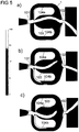
- FIG 4 three snapshots of a fluid flow 2 are shown to illustrate the flow direction (streamlines) of the fluid flow 2 in a fluidic component 1 during an oscillation cycle ( Figures a) to c)).
- the fluidic component 1 from Figure 4 differs from the fluidic component 1 from Figures 1 to 3 in particular in that no separators are provided and that the ends of the blocks 11 facing the inlet opening 101 are less rounded.
- the component length I of the fluidic component 1 from Figure 4 is 18 mm and the component width b is 20 mm ( Figure d)).
- the width b IN of the inlet opening 101 and the width b N of the secondary flow channels 104a, 104b are the same size and are each 2 mm.
- the outlet width b EX is 0.9 mm.
- the component depth is constant in this exemplary embodiment and is 0.9 mm.
- the main flow channel 103 has a maximum width b H between the blocks 11a, 11b of 8 mm.
- the fluid flowing through the fluidic component 1 has a pressure of 56 bar at the inlet opening 101, the fluid being water.
- the fluidic component 1 shown is basically also suitable for gaseous fluids.
- Figures a) and c) show the flow lines for two deflections of the exiting main flow 24, which approximately correspond to the maximum deflections.
- the angle that the exiting main stream 24 sweeps between these two maxima is the oscillation angle ⁇ ( Figure 7 ).
- Figure b) shows the flow lines for a position of the exiting main flow 24 which lies approximately in the middle between the two maxima from Figures a) and c). The flows within the fluidic component 1 during an oscillation cycle are described below.
- the fluid flow 2 is passed into the fluidic component 1 via the inlet opening 101 with an inlet pressure of 56 bar.
- the fluid flow 2 experiences hardly any pressure loss in the area of the inlet opening 101, since it can flow undisturbed into the main flow channel 103.
- the fluid flow 2 initially flows along the longitudinal axis A in the direction of the outlet opening 102.
- the fluid flow 2 is deflected laterally in the direction of the side wall of the one block 11a facing the main flow channel 103, so that the direction of the fluid flow 2 increasingly deviates from the longitudinal axis A until the fluid flow is maximally deflected.
- the major part of the fluid flow 2 the so-called main flow 24
- a recirculation area 25b is formed in the area between the main flow 24 and the other block 11b. The recirculation area 25b grows the more the main flow 24 is applied to the side wall of one block 11a.
- the main flow 24 emerges from the outlet opening 102 at an angle that changes over time with respect to the longitudinal axis A.
- the main flow 24 is on the side wall of the one block 11a and the recirculation area 25b has its maximum size.
- the main flow 24 emerges from the outlet opening 102 with approximately the greatest possible deflection.
- the main flow 24 is thus pressed against the side wall of the block 11a by the impulse (of the secondary flow 23b).
- the recirculation region 25b moves in the direction of the inlet 104b1 of the secondary flow channel 104b, as a result of which the supply of fluid into the secondary flow channel 104b is disturbed.
- the pulse component resulting from the bypass flow 23b thus decreases.
- the recirculation area 25b is reduced in size, while a further (growing) recirculation area 25a is formed between the main flow 24 and the side wall of the block 11a.
- the supply of fluid into the bypass duct 104a also increases.
- the pulse component resulting from the bypass flow 23a thus increases.
- the supply of fluid into the secondary flow channel 104a continues to increase, so that the pulse component resulting from the secondary flow 23a exceeds the pulse component resulting from the secondary flow 23b.
- the main flow 24 is thereby pushed further and further away from the side wall of the block 11a until it rests against the side wall of the opposite block 11b due to the Coanda effect ( Figure 4c )).
- the recirculation area 25b dissolves, while the recirculation area 25a grows to its maximum size.
- the main flow 24 now exits with maximum deflection, which is in comparison to the situation Figure 4a ) has an opposite sign, from the outlet opening 102.
- the recirculation area 25a will then migrate and block the inlet 104a1 of the secondary flow channel 104a, so that the supply of fluid here drops again.
- the secondary flow 23b will deliver the dominant pulse component, so that the main flow 24 is again pushed away from the side wall of the block 11b.
- the main flow 24 exiting at the outlet opening 102 oscillates about the longitudinal axis A in a plane in which the main flow channel 103 and the secondary flow channels 104a, 104b are arranged, so that a fluid jet wandering back and forth is generated.
- a symmetrical structure of the fluidic component 1 is not absolutely necessary.
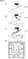
- Figure 5 shows for each of the three snapshots a), b) and c) Figure 4 a corresponding transient flow simulation in order to visualize the velocity field of the fluid flow 2 inside and outside the fluidic component 1.
- Figure 5a of the snapshot Figure 4a ) etc.
- the in Figure 5 The scale shown translates the gray levels in which the fluid flow 2 is mapped into a velocity in m / s of the fluid flow.
- the speed is logarithmically coded with a color code. According to this, black corresponds to a fluid velocity of 0 m / s, while white corresponds to a fluid velocity of 150 m / s. The lighter the fluid is displayed at one point, the higher its speed at that point.
- Figures a) to c) show that the main flow 24 at the outlet opening 102 with a Exits speed which is always higher than the speed at which the fluid flow 2 enters at the inlet opening 101. This is due to the fact that the outlet opening 102 has a smaller cross-sectional area than the inlet opening 101.
- the speed of the exiting main stream 24 is around 150 m / s.
- a fluid jet is thus generated at high speed or high momentum. Despite the high speed of the exiting fluid jet, the oscillation mechanism is retained.
- Figure 6 shows off for the snapshot Figure 4b ) ( Figure 5b )) the corresponding pressure field of the fluid flow 2.
- the pressure is logarithmically coded with a color code. The scale shown ranges from 1 bar (white) to 60 bar (black). Upstream of the inlet opening 101, the pressure of the fluid is 56 bar. The ambient pressure is 1 bar (white).
- Figure 6 clearly shows that the pressure of the fluid in the entire fluidic component 1 is high and essentially corresponds to the pressure before entry into the fluidic component 1 through the inlet opening 101. Only at the outlet opening 102 does the pressure of the fluid drop abruptly to the ambient pressure. In connection with Figure 5b ) it can be seen that the fluid is accelerated at this point of the pressure drop.
- the Figures 7a ) to c) show three individual recordings of a fluid jet emerging from a fluidic component 1 to illustrate the spray characteristics.
- the fluidic component 1 has a component length I of 22 mm, a component width of 23 mm and a component depth of 3 mm.
- the inlet opening 101 has a width b IN of 3 mm, and the outlet opening 102 has a width b EX of 2.5 mm.
- Separators 105a, 105b are provided at the inlets of the bypass ducts 104a, 104b.
- the secondary flow channels 104a, 104b each have a constant width b N of 4 mm.
- the main flow channel 103 is 9 mm wide at its widest point (b H ).
- the fluidic component 1 is flowed through with water as a fluid, wherein in Figure 7a ) the pressure of the water at the inlet port 101 0.5 bar, in Figure 7b ) 2.5 bar and in Figure 7c ) Is 7 bar. As the pressure of the water at the inlet opening 101 rises, the oscillation frequency f of the exiting fluid jet increases, the oscillation angle ⁇ essentially remaining the same.
- FIG. 8 and 9 cross-sections of two further embodiments of the fluidic component 1 are shown.
- the sectional view of the Figures 8 and 9 corresponds to that of Figure 3 .
- the Figures 8 and 9 thus each show a section through the fluidic component 1 transversely to the longitudinal axis A and thus a section through the main flow duct 103 and the secondary flow ducts 104a, 104b transversely to the flow direction.
- the fluidic components from the Figures 8 and 9 correspond to the fluidic component 1 from characters 1 to 3 and differ from the latter only in the cross-sectional shapes of the main flow channel 103 and the secondary flow channels 104a, 104b.
- the Figures 10 and 11 show two further embodiments of the fluidic component 1. These two embodiments differ from that one Figure 1 in particular in that a flow divider 108 is provided in the outlet channel 107, but no separator at the inlets 104a1, 104b1 of the bypass channels 104a, 104b.
- the shape of the blocks 11a, 11b is also different. The fundamental geometric properties of these two embodiments, however, agree with those of the fluidic component 1 Figure 1 match.
- the flow divider 108 each has the shape of a triangular wedge.
- the wedge has a depth which corresponds to the component depth t. (The component depth t is constant over the entire fluidic component 1.)
- the flow divider 108 thus divides the outlet channel 107 into two sub-channels with two outlet openings 102 and the fluid flow 2 into two sub-flows that exit from the fluidic component 1.
- the oscillation mechanism described above the two substrate streams emerge from the two outlet openings 102 in a pulsed manner.
- the two outlet openings 102 each have a smaller width b EX than the inlet opening 101.
- the flow divider 108 extends essentially in the outlet channel 107, while in the embodiment it extends Figure 11 extends into the main flow channel 103.
- the shape and size of the flow divider 108 can in principle be freely selected depending on the desired application.
- a plurality of flow dividers can also be provided (next to one another along the width of the component) in order to subdivide the exiting fluid jet into more than two sub-flows.
- the Figures 10 and 11 also show two further embodiments for the blocks 11a, 11b. However, these shapes are only to be provided by way of example and not exclusively in connection with the flow divider 108. Likewise, the blocks 11a, 11b can be designed differently when using a flow divider 108.
- the blocks out Figure 10 have an essentially trapezoidal basic shape which tapers downstream (in width) and from the ends of which a triangular projection protrudes into the main flow channel 103. Blocks 11a, 11b from Figure 11 resemble those from Figure 1 , but do not have rounded corners.
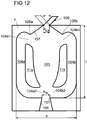
- Figure 12 shows the fluidic component 1 from Figure 1 , which additionally has a fluid flow guide 109.
- the fluid flow guide 109 is a tubular extension which is arranged at the outlet opening 102 and extends downstream from the outlet opening 102.
- the fluid flow guide 109 serves to bundle the exiting fluid flow without affecting the oscillation mechanism.
- the fluid flow guide 109 is movably arranged on the outlet opening 102 and is moved along by the movement of the exiting fluid flow. This is in Figure 12 illustrated by the double arrow.
- one of the two maximum deflections of the fluid flow guide 109 is shown as a continuous line and the other of the two maximum deflections of the fluid flow guide 109 is shown as a dotted line.
- FIG. 11 shows a further embodiment for the fluidic component 1 with the fluid flow guide 109 Figure 12 shown.
- the fluidic component 1 additionally has a flow guide body 110, which is connected to the fluid flow guide 109 by means of a holder 111.
- the flow guide body 110 serves to support the deflection of the fluid flow emerging from the outlet opening 102 and thus also the movement of the fluid flow guide 109 utilizing the fluid dynamics in the flow chamber 10.
- the holder 111 is designed in such a way that it does not interfere with the oscillation mechanism of the emerging fluid flow. In particular, the holder has a small cross section and thus a negligible flow resistance.
- the holder 111 produces a rigid connection between the flow guide body 110 and the fluid flow guide 109.
- the flow guide body 110 is therefore not movable with respect to the fluid flow guide 109, but rather only together with the fluid flow guide 109.
- the shape of the flow guide body 110 can be designed differently. In particular, the flow guide body 110 can be streamlined. In the Figure 13 The rectangular shape of the flow guide body 110 shown is only a schematic illustration.
- Flow guide body 110 described is not based on that in Figure 13
- the fluidic component 1 shown is limited, but can also be used in other fluidic components 1 with a fluid flow guide 109.
- the fluid flow guide 109 can also be used in other fluidic components besides those from the Figures 12 and 13 can be used.
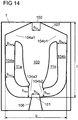
- Figure 14 shows a fluidic component 1, which is essentially the fluidic component 1 from Figure 1 corresponds.
- the fluidic component 1 from Figure 14 differs from that Figure 1 in that the cross-sectional area of the secondary flow channels 104a, 104b is not constant over their length.
- the component depth of the fluidic component 1 from Figure 14 is constant over the entire fluidic component 1.
- the cross-sectional area of the secondary flow channels 104a, 104b is accordingly achieved by changing their width.
- the secondary flow channel 104a thus has a greater width at its inlet 104a1 and at its outlet 104a2 than in a section between inlet 104a1 and outlet 104a2.
- the widths b Na1 , b Na2 , b Na3 of the secondary flow channel 104a shown are b Na1 > b Na2 and b Na3 > b Na2 .
- b Na3 > b Na1 , but b Na3 b Na1 or b Na3 ⁇ b Na1 can also apply.
- the secondary flow channel 104b has a greater width at its inlet 104b1 than at its outlet 104b2.
- the widths b Nb1 , b Nb2 of the secondary flow channel 104b shown are b Nb1 > b Nb2 .
- the entrance width can be smaller than the exit width.
- the width of the bypass channels 104a, 104b changes differently over their length. This is achieved in that the two blocks 11a, 11b are designed differently in shape and size and are not aligned symmetrically with respect to the mirror plane S2. As a result, the shape of the main flow channel 103 is also not symmetrical to the mirror plane S2. However, both secondary flow channels 104a, 104b can behave the same with regard to their change in width.
- the manufacturing process (casting, sintering) of the fluidic component 1 can be simplified, since foreign substances can easily be removed from the fluidic component during manufacture.
- the finished fluidic component can be cleaned more easily, which plays a role, for example, when the fluidic component is used with a foreign substance-laden (particle-laden) fluid.
- the variant in which If the cross-section from the outlet of the bypass duct to the inlet of the bypass duct increases, the fluidic component flushes itself free during operation.
- the fluid runs completely out of the fluidic component when the fluidic component is switched off (i.e. when no more fluid is passed into the fluidic component). It can thus be avoided that fluid collects in the fluidic component after switching off and that pathogens (for example Legionella) in the fluid multiply or mold, soap residues, lime or other dirt build up.
- pathogens for example Legionella
- An emptying of the fluidic component after switching off can be supported by dispensing with separators.
- variable width of the secondary flow channels 104a, 104b described is not limited to the in Figure 14 shown fluidic component 1 limited. Rather, the variable width of the secondary flow channels / of the secondary flow channel can also be applied to other forms of fluidic components with one or more secondary flow channels.
- a fluidic component 1 which has a cavity 112 downstream of the outlet opening 102. Otherwise it corresponds to the fluidic component Figure 4d ).
- the cavity 112 is an annular widening of the outlet channel 107 adjoining the outlet opening 102, which (viewed in the flow direction of the exiting fluid flow) extends over a section of the outlet channel 107.
- An annular widening is to be understood as a widening that has a round, angular, oval or otherwise shaped, closed contour.
- the cavity is arranged directly at the outlet opening 102. However, it can also be arranged further downstream.
- the cavity 112 reduces the boundary layer height of the fluid flow emerging from the outlet opening 102.
- the cavity 112 can be provided for the most varied of embodiments of a fluidic component 1 and is not aimed at the fluidic component 1 Figure 15 limited.
- FIG 16 a fluidic component 1 according to a further embodiment of the invention is shown schematically.
- the Figures 17 and 18 show a sectional view of this fluidic component 1 along the lines A'-A "and B'-B".
- the fluidic component 1 from the Figures 16 to 18 corresponds essentially to the fluidic component from the Figures 1 to 3 .
- the fluidic component 1 from the Figures 16 to 18 differs from the fluidic component from the Figures 1 to 3 in particular that an outlet widening 12 is provided.
- the outlet widening 12 adjoins the outlet opening 102 downstream.
- the fluid flow 2 thus moves from the outlet opening 102 through the outlet widening 12 before the fluid flow 2 emerges from the fluidic component 1.
- the pressure within the fluidic component 1 can increase and thus reduce the inclination of the cavity.
- the inlet pressure which is, for example, higher than 14 bar (compared to the ambient pressure), but can also be above 1000 bar, and is preferably between 20 bar and 500 bar, is essentially only reduced at the outlet opening 102. Due to the high pressure reduction directly at the outlet opening 102, the exiting fluid jet can tend to burst (in all directions). This bursting can be counteracted (at least partially) by the outlet widening 12.
- the exiting fluid jet can be bundled (perpendicular to the planes of symmetry S1 and S2). By bundling the fluid jet in this way, an increase in the removal or cleaning performance of the fluidic component 1 can be achieved.
- the outlet widening 12 is funnel-shaped and has a cross-sectional area which, starting from the outlet opening 102, increases in the fluid flow direction (from the inlet opening 101 to the outlet opening 102).
- the depth of the outlet expansion 12 is constant, while the width of the outlet expansion 12 increases in the direction of the fluid flow. According to Figure 16 the width increases linearly. However, a steady increase other than the linear increase in width is also possible.
- the outlet opening 102 forms the point with the smallest cross-sectional area between the flow chamber 10 and the outlet expansion 12.
- the walls delimiting the outlet expansion 12 enclose an angle ⁇ in the plane in which the exiting fluid jet oscillates.
- the angle ⁇ corresponds in the embodiment from Figure 16 the oscillation angle ⁇ of the exiting fluid jet, which would be formed without the outlet widening 12.
- the angle ⁇ can also be greater than the corresponding oscillation angle ⁇ be formed.
- a fluidic component 1 that generates a uniform distribution of the fluid on the surface to be sprayed (also known as a histogram) without an outlet expansion 12
- a fluidic component 1 without an outlet widening 12 generates an uneven distribution of the fluid on the surface to be sprayed (for example more fluid in the center than in the edge areas) or in the event that a smaller spray angle or oscillation angle ⁇ is desired
- An outlet widening 12 can be provided, the angle ⁇ of which corresponds to the desired reduced oscillation angle ⁇ . In this way, on the one hand, a smaller oscillation angle ⁇ is generated and, on the other hand, a more uniform distribution of the fluid on the surface to be sprayed or in the histogram is generated.
- the walls delimiting the outlet channel 107 enclose an angle ⁇ in the plane in which the exiting fluid jet oscillates.
- the angle ⁇ of the outlet channel 107 can be larger than the oscillation angle ⁇ and also larger than the angle ⁇ of the outlet widening 12.
- the angle ⁇ of the outlet channel 107 is preferably at least 1.1 times greater than the angle ⁇ of the outlet widening 12. According to a particularly preferred embodiment, 1.1 * ⁇ ⁇ 3.5 * ⁇ applies.
- the outlet widening 12 has a length I out which adjoins the component length I.
- the length I out of the outlet expansion 12 can correspond at least to the width b EX of the outlet opening 102.
- the length I out of the outlet widening 12 can preferably be greater than the width b EX of the outlet opening 102 by at least a factor of 1.25.
- the length I out of the outlet extension 12 can preferably be a factor of 1 to 32 greater than the outlet width b EX , particularly preferably a factor of 4 to 16. With this ratio, a fluid jet with high jet quality can be generated.
- the separators 105a, 105b are formed by an indentation in the wall of the secondary flow channels 104a, 104b.
- the indentation has a shape that describes an arc in the plane of symmetry S1.
- the radius of the circular arc can be of different strengths.
- the radius of the circular arc can be 0.0075 to 2.6 times, preferably 0.015 to 1.8 times, and particularly preferably 0.055 to 1.7 times the outlet width b EX .
- the component depth t is constant over the entire outlet widening 12 and corresponds to the component depth at the outlet opening 102 exists.
- the depth t of the outlet widening 12 can increase or decrease downstream (compared to the component depth that is present at the outlet opening 102).
- a further focusing of the exiting fluid jet can be achieved by reducing the component depth in the area of the outlet widening 12 in a downstream direction.
- a fluidic component 1 according to a further embodiment of the invention is shown schematically.
- This fluidic component like the fluidic component 1 from FIG Figure 16 an outlet expansion 12.
- the shapes of the secondary flow channels 104a, 104b, the blocks 11a, 11b and the separators 105a, 105b are similar to the shapes of the fluidic component 1 Figure 7d ).
- the basic shape of the fluidic component 1 from Figure 19 is essentially rectangular.
- the blocks 11a and 11b have an essentially rectangular basic shape, at whose end facing the inlet opening 101 a triangular projection adjoins, which protrudes into the main flow channel.
- the blocks 11a and 11b can be sharp-edged or slightly rounded at the meeting points of the straight sections, as in FIG Figure 19 shown.
- the secondary flow channels 104a, 104b extend, starting from the inlet opening 101 in a first section, each initially at an angle of essentially 90 ° to the longitudinal axis A in opposite directions. Subsequently, the secondary flow channels 104a, 104b bend (essentially at right angles) so that they each extend essentially parallel to the longitudinal axis A (in the direction of the outlet opening 102) (second section). The second section is followed by a third section. The change in direction during the transition from the second to the third section is essentially 90 °.
- the separators 105a, 105b are made of Figure 16 not formed by an indentation in the wall of the bypass ducts 104a, 104b, but rather by the transition of the straight third section of the bypass ducts 104a, 104b (which extends essentially perpendicular to the longitudinal axis A and the plane of symmetry S2) into the wall of the outlet duct 107, which forms an angle smaller than 90 ° with the longitudinal axis A (and the plane of symmetry S2).
- the separators 105a, 105b are accordingly formed by an edge.
- the separators 105a, 105b (as in the embodiment from FIGS Figures 16 to 18 ) have a shape that describes an arc in the plane of symmetry S1.
- the third section of the secondary flow channels 104a, 104b extends essentially perpendicular to the plane of symmetry S2, but the angle can also deviate from 90 °.
- the separators 105a, 105b can preferably be arranged at a distance from the plane of symmetry S2 which lies within the mean width of the blocks 11a, 11b.
- FIG Figures 16 to 19 The shape of the fluidic components 1 with an outlet expansion 12 is shown in FIG Figures 16 to 19 shown only as an example.
- the outlet widening 12 can also be provided in connection with other embodiments of the fluidic component 1 according to the invention.
Landscapes
- Engineering & Computer Science (AREA)
- Chemical & Material Sciences (AREA)
- Mechanical Engineering (AREA)
- General Engineering & Computer Science (AREA)
- Combustion & Propulsion (AREA)
- Analytical Chemistry (AREA)
- Physics & Mathematics (AREA)
- Fluid Mechanics (AREA)
- Nozzles (AREA)
- Measuring Volume Flow (AREA)
- Jet Pumps And Other Pumps (AREA)
- Physical Or Chemical Processes And Apparatus (AREA)
Description
Die Erfindung betrifft ein fluidisches Bauteil nach dem Oberbegriff des Anspruchs 1 und ein Reinigungsgerät, das ein solches fluidisches Bauteil umfasst. Das fluidische Bauteil ist zur Erzeugung eines sich bewegenden Fluidstrahls vorgesehen. Beispielhafte fluidische Bauteile sind z.B. aus
Aus dem Stand der Technik sind zur Erzeugung eines Fluidstrahls mit hoher Geschwindigkeit beziehungsweise hohem Impuls Düsen bekannt, die ausgebildet sind, den Fluidstrahl mit einem Druck zu beaufschlagen, der höher ist als der Umgebungsdruck. Mittels der Düse wird das Fluid beschleunigt und / oder gerichtet beziehungsweise gebündelt. Um eine Bewegung eines Fluidstrahls zu erzeugen, wird die Düse in der Regel mittels einer Vorrichtung bewegt. Zur Erzeugung eines beweglichen Fluidstrahls ist somit neben der Düse eine zusätzliche Vorrichtung erforderlich. Diese zusätzliche Vorrichtung umfasst bewegliche Komponenten, die einfach verschleißen können. Die mit der Herstellung und Wartung verbundenen Kosten sind entsprechend hoch. Nachteilig ist ferner, dass aufgrund der beweglichen Komponenten insgesamt ein relativ großer Bauraum erforderlich ist.For generating a fluid jet at high speed or high impulse, nozzles are known from the prior art which are designed to apply a pressure to the fluid jet which is higher than the ambient pressure. The fluid is accelerated and / or directed or bundled by means of the nozzle. In order to generate a movement of a fluid jet, the nozzle is usually moved by means of a device. In order to generate a movable fluid jet, an additional device is required in addition to the nozzle. This additional device includes moving components that can easily wear out. The costs associated with production and maintenance are correspondingly high. Another disadvantage is that, due to the movable components, a relatively large overall space is required.
Zur Erzeugung eines beweglichen Fluidstroms (oder Fluidstrahls) sind ferner fluidische Bauteile bekannt. Die fluidischen Bauteile umfassen keine beweglichen Komponenten, die der Erzeugung eines beweglichen Fluidstroms dienen. Dadurch weisen sie im Vergleich zu den eingangs erwähnten Düsen nicht die aus den beweglichen Komponenten resultierenden Nachteile auf. Jedoch tritt bei den bekannten fluidischen Bauteilen innerhalb der fluidischen Bauteile regelmäßig ein starker Druckgradient auf, so dass es beim Durchströmen der fluidischen Bauteile mit einem flüssigen Fluidstrom innerhalb der Bauteile zu Kavitation, also zur Ausbildung von Hohlräumen (Blasen), kommen kann. Hierdurch kann sich die Lebensdauer der Bauteile massiv reduzieren oder ein Ausfall der fluidischen Bauteile herbeigeführt werden. Auch sind die bekannten fluidischen Bauteile eher zur Benetzung von Oberflächen geeignet als zur Erzeugung eines Fluidstrahls mit hoher Geschwindigkeit beziehungsweise mit hohem Impuls. So weist ein aus einem bekannten fluidischen Bauteil austretender Fluidstrom die Spraycharakteristik einer Flachstrahldüse auf, die einen fein zerstäubten Strahl erzeugt.Fluidic components are also known for generating a movable fluid flow (or fluid jet). The fluidic components do not include any movable components that are used to generate a movable fluid flow. As a result, compared to the nozzles mentioned at the beginning, they do not have the disadvantages resulting from the movable components. However, with the known fluidic components within the fluidic components, a strong pressure gradient occurs regularly, so that cavitation, i.e. the formation of cavities (bubbles), can occur when a liquid fluid flow flows through the fluidic components. This can massively reduce the service life of the components or cause the fluidic components to fail. The known fluidic components are also more suitable for wetting surfaces than for generating a fluid jet at high speed or with high momentum. For example, a fluid flow emerging from a known fluidic component has the spray characteristics of a flat jet nozzle which generates a finely atomized jet.
Der vorliegenden Erfindung liegt die Aufgabe zugrunde, ein fluidisches Bauteil zu schaffen, das ausgebildet ist, einen sich beweglichen Fluidstrahl mit hoher Geschwindigkeit beziehungsweise hohem Druck zur Verfügung zu stellen, wobei das fluidische Bauteil eine hohe Ausfallsicherheit und einen entsprechend geringeren Wartungsaufwand aufweist.The present invention is based on the object of creating a fluidic component that is designed to provide a moving fluid jet at high speed or high pressure, the fluidic component having a high level of failure safety and correspondingly lower maintenance costs.
Diese Aufgabe wird erfindungsgemäß durch ein fluidisches Bauteil mit den Merkmalen des Anspruchs 1 gelöst. Ausgestaltungen der Erfindung sind in den Unteransprüchen angegeben.According to the invention, this object is achieved by a fluidic component having the features of
Danach umfasst das fluidische Bauteil eine Strömungskammer, die von einem Fluidstrom durchströmbar ist. Der Fluidstrom kann ein Flüssigkeitsstrom oder ein Gasstrom sein. Die Strömungskammer umfasst eine Einlassöffnung und eine Auslassöffnung, durch die der Fluidstrom in die Strömungskammer eintritt beziehungsweise aus der Strömungskammer wieder austritt. Das fluidische Bauteil umfasst ferner mindestens ein Mittel zur gezielten Richtungsänderung des Fluidstroms an der Auslassöffnung, wobei das Mittel insbesondere zur Ausbildung einer räumlichen Oszillation des Fluidstroms an der Auslassöffnung ausgebildet ist. Die Strömungskammer weist einen Hauptstromkanal, der die Einlassöffnung und die Auslassöffnung miteinander verbindet, und mindestens einen Nebenstromkanal als das mindestens eine Mittel zur gezielten Richtungsänderung des Fluidstroms an der Auslassöffnung auf.According to this, the fluidic component comprises a flow chamber through which a fluid flow can flow. The fluid flow can be a liquid flow or a gas flow. The flow chamber comprises an inlet opening and an outlet opening through which the fluid flow enters the flow chamber or exits the flow chamber again. The fluidic component further comprises at least one means for the targeted change of direction of the fluid flow at the outlet opening, the means being designed in particular to form a spatial oscillation of the fluid flow at the outlet opening. The flow chamber has a main flow channel which connects the inlet opening and the outlet opening to one another, and at least one secondary flow channel as the at least one means for the targeted change in direction of the fluid flow at the outlet opening.
Das fluidische Bauteil zeichnet sich dadurch aus, dass die Einlassöffnung eine größere Querschnittsfläche als die Auslassöffnung aufweist oder dass die Einlassöffnung und die Auslassöffnung eine gleich große Querschnittsfläche aufweisen. Hierbei sind unter den Querschnittsflächen der Einlassöffnung und der Auslassöffnung jeweils die kleinsten Querschnittsflächen des fluidischen Bauteils zu verstehen, die der Fluidstrom passiert, wenn er in die Strömungskammer eintritt beziehungsweise aus der Strömungskammer wieder austritt.The fluidic component is characterized in that the inlet opening has a larger cross-sectional area than the outlet opening or that the inlet opening and the outlet opening have the same cross-sectional area. Here, the cross-sectional areas of the inlet opening and the outlet opening are to be understood to mean the smallest cross-sectional areas of the fluidic component that the fluid flow passes when it enters the flow chamber or exits the flow chamber again.
Hierdurch wird erreicht, dass ein räumlich (und zeitlich) oszillierender Fluidstrahl aus dem fluidischen Bauteil austritt, der eine hohe Geschwindigkeit beziehungsweise einen hohen Impuls aufweist. Dabei ist der austretende Fluidstrahl zudem kompakt, das heißt, dass der Fluidstrahl erst spät (weit stromabwärts) und nicht unmittelbar an der Auslassöffnung räumlich auffächert oder aufplatzt.This ensures that a spatially (and temporally) oscillating fluid jet emerges from the fluidic component, which jet has a high speed or a high impulse. The exiting fluid jet is also compact, which means that the fluid jet only fanned out or bursts spatially late (far downstream) and not directly at the outlet opening.
Auf bewegliche Komponenten zur Erzeugung eines oszillierenden Strahls kann in der erfindungsgemäßen Anordnung verzichtet werden, so dass hierdurch bedingte Kosten und Aufwendungen nicht anfallen. Zudem ist durch den Verzicht auf bewegliche Komponenten die Vibrations- und Geräuschentwicklung des erfindungsgemäßen fluidischen Bauteils relativ gering.Movable components for generating an oscillating beam can be dispensed with in the arrangement according to the invention, so that costs and expenditures caused by this do not arise. In addition, by dispensing with moving components, the development of vibration and noise in the fluidic component according to the invention is relatively low.
Auch wird das Auftreten einer Kavitation innerhalb des fluidischen Bauteils (und die daraus resultierenden Nachteile) durch die erfindungsgemäße Wahl des Größenverhältnisses von Einlassöffnung zu Auslassöffnung vermieden. Entgegen der vorherrschenden Meinung wird die Ausbildung des oszillierenden Fluidstrahls nicht dadurch beeinträchtigt, dass die Auslassöffnung eine kleinere Querschnittsfläche als die Einlassöffnung hat.The occurrence of cavitation within the fluidic component (and the disadvantages resulting therefrom) is also avoided by the inventive choice of the size ratio of inlet opening to outlet opening. Contrary to the prevailing opinion, the formation of the oscillating fluid jet is not impaired by the fact that the outlet opening has a smaller cross-sectional area than the inlet opening.
Der räumlich oszillierende Fluidstrahl, der aus dem erfindungsgemäßen fluidischen Bauteil austritt, weist aufgrund seiner Kompaktheit und hohen Geschwindigkeit eine hohe Abtragungs- und Reinigungsleistung auf, wenn er auf eine Oberfläche gerichtet wird. Daher kann das erfindungsgemäße fluidische Bauteil beispielsweise in der Reinigungstechnik angewandt werden. Auch für die Mischungstechnik (bei der zwei oder mehr unterschiedliche Fluide miteinander gemischt werden sollen) und die Fertigungstechnik (zum Beispiel Wasserstrahlschneiden) ist das erfindungsgemäße fluidische Bauteil interessant. So kann beispielsweise die Effektivität des Wasserstrahlschneidens mit einem aus dem erfindungsgemäßen fluidischen Bauteil austretenden pulsierenden Fluidstrahl erhöht werden.The spatially oscillating fluid jet which emerges from the fluidic component according to the invention has a high removal and cleaning capacity due to its compactness and high speed when it is directed onto a surface. The fluidic component according to the invention can therefore be used, for example, in cleaning technology. The fluidic component according to the invention is also of interest for mixing technology (in which two or more different fluids are to be mixed with one another) and production technology (for example water jet cutting). For example, the effectiveness of water jet cutting can be increased with a pulsating fluid jet emerging from the fluidic component according to the invention.
Prinzipiell kann die Querschnittsfläche der Einlassöffnung gleich groß wie oder größer als die Querschnittsfläche der Auslassöffnung sein. Das Größenverhältnis kann je nach den gewünschten Charakteristiken (Geschwindigkeit beziehungsweise Impuls, Kompaktheit, Oszillationsfrequenz) des austretenden Strahls gewählt werden. Jedoch können auch andere Parameter, wie beispielsweise die Größe (zum Beispiel das Volumen und/oder die Bauteiltiefe, Bauteilbreite, Bauteillänge) des fluidischen Bauteils, die Form des fluidischen Bauteils, die Art des Fluids (Gas, Flüssigkeit mit niedriger Viskosität, Flüssigkeit mit hoher Viskosität), die Größe des Drucks, mit dem der Fluidstrom beaufschlagt in das fluidische Bauteil eintritt, die Eingangsgeschwindigkeit des Fluids und der Volumendurchfluss die Wahl des Größenverhältnisses beeinflussen. Die Oszillationsfrequenz kann zwischen 0,5 Hz und 30 kHz liegen. Ein bevorzugter Frequenzbereich befindet sich zwischen 3 Hz und 400 Hz. Der Eingangsdruck kann zwischen 0,01 bar und 6000 bar über dem Umgebungsdruck liegen. Für einige Anwendungen (sogenannte) Niederdruckanwendungen, wie beispielsweise für Waschmaschinen oder Geschirrspüler, liegt der Eingangsdruck typischerweise zwischen 0,01 bar und 12 bar über dem Umgebungsdruck. Für andere Anwendungen (sogenannte Hochdruckanwendungen), wie beispielsweise für die Reinigung (von Fahrzeugen, Halbzeugen, Maschinen oder Ställen) oder die Mischung von zwei unterschiedlichen Fluiden, liegt der Eingangsdruck typischerweise zwischen 5 bar und 300 bar.In principle, the cross-sectional area of the inlet opening can be the same size as or larger than the cross-sectional area of the outlet opening. The size ratio can be selected depending on the desired characteristics (speed or pulse, compactness, oscillation frequency) of the emerging beam. However, other parameters, such as the size (for example the volume and / or the component depth, component width, component length) of the fluidic component, the shape of the fluidic component, the type of fluid (gas, liquid with low viscosity, liquid with high Viscosity), the size of the pressure with which the fluid flow enters the fluidic component, the input speed of the fluid and the volume flow influence the choice of the size ratio. The oscillation frequency can be between 0.5 Hz and 30 kHz. A preferred frequency range is between 3 Hz and 400 Hz. The inlet pressure can be between 0.01 bar and 6000 bar above ambient pressure. For some applications (so-called) low pressure applications, such as washing machines or dishwashers, the inlet pressure is typically between 0.01 bar and 12 bar above the ambient pressure. For other applications (so-called high pressure applications), such as cleaning (of vehicles, semi-finished products, machines or stables) or the mixing of two different fluids, the inlet pressure is typically between 5 bar and 300 bar.
Gemäß einer bevorzugten Ausführungsform kann die Querschnittsfläche der Einlassöffnung um einen Faktor von bis zu 2,5 größer sein als die Querschnittsfläche der Auslassöffnung. Gemäß einer besonders bevorzugten Ausführungsform kann die Querschnittsfläche der Einlassöffnung um einen Faktor von bis zu 1,5 größer sein als die Querschnittsfläche der Auslassöffnung.According to a preferred embodiment, the cross-sectional area of the inlet opening can be larger by a factor of up to 2.5 than the cross-sectional area of the outlet opening. According to a particularly preferred embodiment, the cross-sectional area of the inlet opening can be a factor of up to 1.5 larger than the cross-sectional area of the outlet opening.
Zudem kann die Querschnittsfläche der Auslassöffnung eine beliebige Form, wie beispielsweise quadratisch, rechteckig, polygonal, rund, oval usw. haben. Entsprechendes gilt für die Querschnittsfläche der Einlassöffnung. Dabei kann die Form der Einlassöffnung der Form der Auslassöffnung entsprechen oder sich von letzterer unterscheiden. Eine runde Querschnittsfläche der Auslassöffnung kann beispielsweise gewählt werden, um einen besonders kompakten / gebündelten Fluidstrahl zu erzeugen. Ein solcher Fluidstrahl kann insbesondere in der Hochdruckreinigungstechnik oder beim Wasserstrahlschneiden zum Einsatz kommen.In addition, the cross-sectional area of the outlet opening can have any shape, such as square, rectangular, polygonal, round, oval, etc., for example. The same applies to the cross-sectional area of the inlet opening. The shape of the inlet opening can correspond to the shape of the outlet opening or differ from the latter. A round cross-sectional area of the outlet opening can be selected, for example, in order to generate a particularly compact / bundled fluid jet. Such a fluid jet can be used in particular in high-pressure cleaning technology or in water jet cutting.
Gemäß einer Ausführungsform weisen sowohl die Einlassöffnung als auch die Auslassöffnung einen rechteckigen Querschnitt auf. Dabei kann die Einlassöffnung eine größere Breite als die Auslassöffnung aufweisen.According to one embodiment, both the inlet opening and the outlet opening have a rectangular cross section. The inlet opening can have a greater width than the outlet opening.
Die Breite von Ein- und Auslassöffnung ist dabei bezüglich der Geometrie des fluidischen Bauteils definiert. Das fluidische Bauteil kann beispielsweise im Wesentlichen quaderförmig ausgebildet sein und entsprechend eine Bauteillänge, eine Bauteilbreite und eine Bauteiltiefe aufweisen, wobei die Bauteillänge den Abstand zwischen der Einlassöffnung und der Auslassöffnung bestimmt und die Bauteilbreite und die Bauteiltiefe jeweils senkrecht zueinander und zu der Bauteillänge definiert sind und wobei die Bauteilbreite größer ist als die Bauteiltiefe. Die Bauteillänge erstreckt sich also im Wesentlichen parallel zur Hauptausbreitungsrichtung des Fluidstroms, der sich bestimmungsgemäß von der Einlassöffnung zur Auslassöffnung bewegt. Liegen die Ein- und die Auslassöffnung auf einer Achse, die sich parallel zur Bauteillänge erstreckt, so entspricht der Abstand zwischen der Ein- und der Auslassöffnung der Bauteillänge. Sind die Ein- und die Auslassöffnung versetzt zueinander angeordnet, erstreckt sich die besagte Achse also in einem Winkel ungleich 0° zu der Bauteillänge, so bestimmen die Bauteillänge und der Versatz von Ein- und Auslassöffnung den Abstand zwischen der Ein- und der Auslassöffnung entlang der Achse. Bei einem im Wesentlichen quaderförmigen fluidischen Bauteil kann das Verhältnis von Bauteillänge zu Bauteilbreite von 1/3 bis 5 betragen. Das Verhältnis liegt bevorzugt im Bereich von 1/1 bis 4/1. Die Bauteilbreite kann in dem Bereich zwischen 0,15 mm und 2,5 m liegen. Bei einer bevorzugten Ausführungsvariante liegt die Bauteilbreite zwischen 1,5 mm und 200 mm. Die genannten Dimensionen hängen insbesondere von der Anwendung, für die das fluidische Bauteil eingesetzt werden soll, ab.The width of the inlet and outlet opening is defined in relation to the geometry of the fluidic component. The fluidic component can, for example, be essentially cuboid and accordingly have a component length, a component width and a component depth, the component length determining the distance between the inlet opening and the outlet opening and the component width and the component depth being defined perpendicular to each other and to the component length and where the component width is greater than the component depth. The component length thus extends essentially parallel to the main direction of propagation of the fluid flow, which is intended to move from the inlet opening to the outlet opening. If the inlet and outlet openings lie on an axis that extends parallel to the component length, the distance between the inlet and outlet openings corresponds to the component length. If the inlet and outlet openings are arranged offset from one another, said opening extends If the axis is at an angle not equal to 0 ° to the component length, the component length and the offset of the inlet and outlet openings determine the distance between the inlet and outlet openings along the axis. In the case of an essentially cuboid fluidic component, the ratio of component length to component width can be 1/3 to 5. The ratio is preferably in the range from 1/1 to 4/1. The component width can be in the range between 0.15 mm and 2.5 m. In a preferred embodiment, the component width is between 1.5 mm and 200 mm. The dimensions mentioned depend in particular on the application for which the fluidic component is to be used.
Die zuvor erwähnte Breite von Ein- und Auslassöffnung erstreckt sich definitionsgemäß parallel zu der Bauteilbreite. Gemäß einer Ausführungsform kann ein im Wesentlichen quaderförmiges fluidisches Bauteil eine rechteckige Auslassöffnung mit einer Breite aufweisen, die 1/3 bis 1/50 der Bauteilbreite entspricht, und eine rechteckige Einlassöffnung mit einer Breite, die 1/3 bis 1/20 der Bauteilbreite entspricht. Gemäß einer bevorzugten Ausführungsform kann die Breite der Auslassöffnung 1/5 bis 1/15 der Bauteilbreite und die Breite der Einlassöffnung 1/5 bis 1/10 der Bauteilbreite entsprechen. Das Verhältnis von Bauteiltiefe zu der Breite der Einlassöffnung kann 1/20 bis 5 betragen. Dieses Verhältnis wird auch als Aspektverhältnis bezeichnet. Ein bevorzugtes Aspektverhältnis liegt zwischen 1/6 und 2. Auch die genannten Größenverhältnisse hängen insbesondere von der Anwendung, für die das fluidische Bauteil eingesetzt werden soll, ab.The aforementioned width of the inlet and outlet opening extends, by definition, parallel to the component width. According to one embodiment, a substantially cuboid fluidic component can have a rectangular outlet opening with a width that corresponds to 1/3 to 1/50 of the component width, and a rectangular inlet opening with a width that corresponds to 1/3 to 1/20 of the component width. According to a preferred embodiment, the width of the outlet opening can correspond to 1/5 to 1/15 of the component width and the width of the
Gemäß einer weiteren Ausführungsform weist das fluidische Bauteil eine Bauteiltiefe auf, die über die gesamte Bauteillänge konstant ist. Alternativ kann die Bauteiltiefe (stetig (mit oder ohne konstantem/n Anstieg) oder sprunghaft) von der Einlassöffnung hin zur Auslassöffnung abnehmen. Durch die abnehmende Bauteiltiefe wird der Fluidstrahl innerhalb des fluidischen Bauteils vorgebündelt, so dass ein kompakter Fluidstrahl aus dem fluidischen Bauteil austritt. Ein Aufweiten beziehungsweise Aufplatzen des Fluidstrahls kann somit verzögert werden und erfolgt damit nicht unmittelbar an der Auslassöffnung, sondern erst weiter stromabwärts. Diese Maßnahme ist beispielsweise in der Reinigungstechnik oder in die Wasserstrahltechnik vorteilhaft. Gemäß einer weiteren Alternative kann die Bauteiltiefe von der Einlassöffnung hin zur Auslassöffnung zunehmen, wobei die Bauteilbreite derart abnimmt, dass die Querschnittsfläche der Auslassöffnung kleiner oder gleich groß ist als/wie die Querschnittsfläche der Einlassöffnung.According to a further embodiment, the fluidic component has a component depth that is constant over the entire component length. Alternatively, the component depth can decrease (steadily (with or without constant increase) or abruptly) from the inlet opening towards the outlet opening. Due to the decreasing component depth, the fluid jet is pre-bundled within the fluidic component, so that a compact fluid jet emerges from the fluidic component. A widening or bursting of the fluid jet can thus be delayed and thus does not take place directly at the outlet opening, but only further downstream. This measure is advantageous, for example, in cleaning technology or in water jet technology. According to a further alternative, the component depth can increase from the inlet opening to the outlet opening, the component width decreasing such that the cross-sectional area of the outlet opening is smaller than or equal to the cross-sectional area of the inlet opening.
Als Mittel zur gezielten Richtungsänderung des Fluidstroms an der Auslassöffnung weist die Strömungskammer mindestens einen Nebenstromkanal auf. Der Nebenstromkanal ist von einem Teil des Fluidstroms, dem Nebenstrom, durchströmbar. Der Teil des Fluidstroms, der nicht in den Nebenstromkanal eintritt sondern aus dem fluidischen Bauteil austritt, wird als Hauptstrom bezeichnet. Der mindestens eine Nebenstromkanal kann einen Eingang, der sich in der Nähe der Auslassöffnung befindet, und einen Ausgang aufweisen, der sich in der Nähe der Einlassöffnung befindet. Der mindestens eine Nebenstromkanal kann in Fluidstromrichtung (von der Einlassöffnung zur Auslassöffnung) betrachtet neben (nicht hinter oder vor) dem Hauptstromkanal angeordnet sein. Insbesondere können zwei Nebenstromkanäle vorgesehen sein, die sich (in Hauptstromrichtung betrachtet) seitlich neben dem Hauptstromkanal erstrecken, wobei der Hauptstromkanal zwischen den beiden Nebenstromkanälen angeordnet ist. Gemäß einer bevorzugten Ausführungsform sind die Nebenstromkanäle und der Hauptstromkanal in einer Reihe entlang der Bauteilbreite angeordnet und erstrecken sich jeweils entlang der Bauteillänge. Alternativ können die Nebenstromkanäle und der Hauptstromkanal in einer Reihe entlang der Bauteiltiefe angeordnet sein und sich jeweils entlang der Bauteillänge erstrecken.The flow chamber has at least one secondary flow channel as a means for the targeted change in direction of the fluid flow at the outlet opening. The secondary flow channel can be flowed through by part of the fluid flow, the secondary flow. The part of the fluid flow which does not enter the secondary flow channel but exits the fluidic component is referred to as the main flow. The at least one bypass duct can have an inlet that is located in the vicinity of the outlet opening and an outlet that is located in the vicinity of the inlet opening. The at least one secondary flow channel can be arranged next to (not behind or in front of) the main flow channel when viewed in the fluid flow direction (from the inlet opening to the outlet opening). In particular, two secondary flow channels can be provided which (viewed in the main flow direction) extend laterally next to the main flow channel, the main flow channel being arranged between the two secondary flow channels. According to a preferred embodiment, the secondary flow channels and the main flow channel are arranged in a row along the width of the component and each extend along the length of the component. Alternatively, the secondary flow ducts and the main flow duct can be arranged in a row along the component depth and each extend along the component length.
Vorzugsweise wird der mindestens eine Nebenstromkanal durch einen Block von dem Hauptstromkanal getrennt. Dieser Block kann unterschiedliche Formen aufweisen. So kann sich der Querschnitt des Blocks in Fluidstromrichtung (von der Einlassöffnung zur Auslassöffnung) betrachtet verjüngen. Alternativ kann sich der Querschnitt des Blocks mittig zwischen seinem der Einlassöffnung zugewandten Ende und seinem der Auslassöffnung zugewandten Ende verjüngen oder zunehmen. Auch ist eine Vergrößerung des Querschnitts des Blocks mit zunehmendem Abstand von der Einlassöffnung möglich. Zudem kann der Block abgerundete Kanten aufweisen. Scharfe Kanten können an dem Block insbesondere in der Nähe der Einlassöffnung und / oder der Auslassöffnung vorgesehen sein.The at least one secondary flow channel is preferably separated from the main flow channel by a block. This block can have different shapes. Thus, the cross section of the block can taper in the direction of the fluid flow (from the inlet opening to the outlet opening). Alternatively, the cross section of the block can taper or increase in the middle between its end facing the inlet opening and its end facing the outlet opening. It is also possible to enlarge the cross section of the block as the distance from the inlet opening increases. In addition, the block can have rounded edges. Sharp edges can be provided on the block in particular in the vicinity of the inlet opening and / or the outlet opening.
Gemäß einer Ausführungsform kann der mindestens eine Nebenstromkanal eine größere oder kleinere Tiefe als der Hauptstromkanal aufweisen. Hierdurch kann zusätzlich Einfluss auf die Oszillationsfrequenz des austretenden Fluidstrahls genommen werden. Durch eine Reduktion der Bauteiltiefe im Bereich des mindestens einen Nebenstromkanals (im Vergleich zum Hauptstromkanal) sinkt die Oszillationsfrequenz, wenn die übrigen Parameter im Wesentlichen unverändert bleiben. Entsprechend steigt die Oszillationsfrequenz, wenn die Bauteiltiefe im Bereich des mindestens einen Nebenstromkanals (im Vergleich zum Hauptstromkanal) erhöht wird und die übrigen Parameter im Wesentlichen unverändert bleiben.According to one embodiment, the at least one secondary flow channel can have a greater or smaller depth than the main flow channel. In this way, the oscillation frequency of the exiting fluid jet can also be influenced. By reducing the component depth in the area of the at least one secondary flow channel (compared to the main flow channel), the oscillation frequency drops if the other parameters remain essentially unchanged. The oscillation frequency increases accordingly if the component depth in the area of the at least one secondary flow channel is increased (compared to the main flow channel) and the other parameters remain essentially unchanged.
Eine weitere Möglichkeit, die Oszillationsfrequenz des austretenden Fluidstrahls zu beeinflussen, kann durch mindestens einen Separator geschaffen werden, der vorzugsweise am Eingang des mindestens einen Nebenstromkanals vorgesehen ist. Der Separator unterstützt die Abspaltung des Nebenstroms von dem Fluidstrom. Dabei ist unter einem Separator ein (quer zu der in dem Nebenstromkanal vorherrschenden Strömungsrichtung) am Eingang des mindestens einen Nebenstromkanals in die Strömungskammer hineinragendes Element zu verstehen. Der Separator kann als eine Verformung (insbesondere eine Einbuchtung) der Nebenstromkanalwand oder als ein anderweitig ausgebildeter Vorsprung vorgesehen sein. So kann der Separator (kreis)kegelförmig oder pyramidal ausgebildet sein. Die Verwendung eines solchen Separators ermöglicht neben der Beeinflussung der Oszillationsfrequenz, auch den sogenannten Oszillationswinkel zu variieren. Der Oszillationswinkel ist der Winkel, den der oszillierende Fluidstrahl (zwischen seinen beiden maximalen Auslenkungen) überstreicht. Sind mehrere Nebenstromkanäle vorgesehen, so kann für jeden der Nebenstromkanäle oder nur für einen Teil der Nebenstromkanäle ein Separator vorgesehen sein.Another possibility of influencing the oscillation frequency of the exiting fluid jet can be created by at least one separator which is preferably provided at the entrance of the at least one bypass channel. The separator supports the separation of the secondary flow from the fluid flow. A separator is to be understood as an element projecting into the flow chamber (transversely to the flow direction prevailing in the bypass duct) at the inlet of the at least one bypass duct. The separator can be provided as a deformation (in particular an indentation) of the secondary flow duct wall or as a projection formed in some other way. Thus, the separator (circle) can be conical or pyramidal. The use of such a separator makes it possible not only to influence the oscillation frequency but also to vary the so-called oscillation angle. The angle of oscillation is the angle that the oscillating fluid jet sweeps (between its two maximum deflections). If several secondary flow channels are provided, a separator can be provided for each of the secondary flow channels or only for some of the secondary flow channels.
Gemäß einer Ausführungsform kann unmittelbar stromaufwärts der Auslassöffnung ein Auslasskanal vorgesehen sein. Der Auslasskanal kann eine Querschnittsflächenform aufweisen, die über die gesamte Länge des Auslasskanals konstant ist und der Form der Querschnittsfläche der Auslassöffnung entspricht (quadratisch, rechteckig, polygonal, rund usw.). Alternativ kann sich die Form der Querschnittsfläche des Auslasskanals über die Länge des Auslasskanals ändern. Dabei kann die Größe der Querschnittsfläche der Auslassöffnung konstant bleiben (das ist dann auch die Größe der Auslassöffnung) oder sich ändern. Insbesondere kann sich die Größe der Querschnittsfläche des Auslasskanals in Fluidstromrichtung von der Einlassöffnung zur Auslassöffnung verringern. Gemäß einer weiteren Alternative kann sich die Form und / oder Größe der Querschnittsfläche des Hauptstromkanals von der Einlassöffnung hin zur Auslassöffnung ändern. So kann sich insbesondere die Form der Querschnittsfläche (des Auslasskanals oder des Hauptstromkanals) von rechteckig zu rund (in Fluidstromrichtung von der Einlassöffnung zur Auslassöffnung) ändern. Hierdurch kann der Fluidstrahl bereits im fluidischen Bauteil vorgebündelt werden, so dass die Kompaktheit des austretenden Fluidstrahls erhöht werden kann. Ferner kann sich die Größe der Querschnittsfläche des Auslasskanals ändern, insbesondere in Fluidstromrichtung von der Einlassöffnung zur Auslassöffnung verringern.According to one embodiment, an outlet channel can be provided directly upstream of the outlet opening. The outlet channel can have a cross-sectional shape which is constant over the entire length of the outlet channel and which corresponds to the shape of the cross-sectional area of the outlet opening (square, rectangular, polygonal, round, etc.). Alternatively, the shape of the cross-sectional area of the outlet channel can change over the length of the outlet channel. The size of the cross-sectional area of the outlet opening can remain constant (that is then also the size of the outlet opening) or change. In particular, the size of the cross-sectional area of the outlet channel in the fluid flow direction from the inlet opening to the outlet opening can be reduced. According to a further alternative, the shape and / or size of the cross-sectional area of the main flow channel can change from the inlet opening to the outlet opening. In particular, the shape of the cross-sectional area (of the outlet channel or of the main flow channel) can change from rectangular to round (in the fluid flow direction from the inlet opening to the outlet opening). As a result, the fluid jet can already be pre-bundled in the fluidic component, so that the compactness of the exiting fluid jet can be increased. Furthermore, the size of the cross-sectional area of the outlet channel can change, in particular decrease in the fluid flow direction from the inlet opening to the outlet opening.
Die Form des Auslasskanals beeinflusst den Oszillationswinkel des austretenden Fluidstrahls und kann so gewählt werden, dass sich ein gewünschter Oszillationswinkel einstellt. Neben der zuvor genannten konstanten beziehungsweise variablen Querschnittsflächenform des Auslasskanals kann der Auslasskanal als weiteres Merkmal geradlinig oder gekrümmt ausgebildet sein.The shape of the outlet channel influences the angle of oscillation of the exiting fluid jet and can be selected so that a desired angle of oscillation is established. In addition to the aforementioned constant or variable Cross-sectional shape of the outlet channel, the outlet channel can be designed as a further feature to be straight or curved.
Die Parameter des fluidischen Bauteils (Form, Größe, Anzahl und Form der Nebenstromkanäle, (relative) Größe der Ein- und Auslassöffnung) sind vielfältig einstellbar. Vorzugsweise werden diese Parameter so gewählt, dass der Druck, mit dem der Fluidstrom beaufschlagt über die Einlassöffnung in das fluidische Bauteil eintritt, im Wesentlichen an der Auslassöffnung abgebaut wird. Ein im Vergleich zu dem an der Auslassöffnung erfolgender geringer Druckabbau kann dabei bereits in dem fluidischen Bauteil (stromaufwärts der Auslassöffnung) erfolgen.The parameters of the fluidic component (shape, size, number and shape of the secondary flow channels, (relative) size of the inlet and outlet opening) can be set in a variety of ways. These parameters are preferably selected in such a way that the pressure with which the fluid flow is acted upon and enters the fluidic component via the inlet opening is substantially reduced at the outlet opening. A slight pressure reduction that occurs at the outlet opening can already take place in the fluidic component (upstream of the outlet opening).
Gemäß einer weiteren Ausführungsform weist das fluidische Bauteil zwei oder mehr Auslassöffnungen auf. Diese Auslassöffnungen können durch Anordnung eines Strömungsteilers unmittelbar stromaufwärts der Auslassöffnungen gebildet werden. Der Strömungsteiler ist ein Mittel zum Aufspalten des Fluidstroms in zwei oder mehrere Subströme. Um die eingangs genannten Wirkungen des erfindungsgemäßen fluidischen Bauteils mit nur einer Auslassöffnung auch bei der Ausführungsform mit zwei oder mehr Auslassöffnungen zu erreichen, kann jede Auslassöffnung jeweils eine kleinere Querschnittsfläche als die Einlassöffnung aufweisen oder können alle Auslassöffnungen und die Einlassöffnung jeweils eine gleich große Querschnittsfläche aufweisen. Alternativ kann auch nur eine der zwei / mehreren Auslassöffnungen eine kleinere / gleichgroße Querschnittsfläche als / wie die Einlassöffnung aufweisen. Ein fluidisches Bauteil mit zwei oder mehreren Auslassöffnungen ist geeignet, um zwei oder mehr Fluidstrahlen zu erzeugen, die zeitlich pulsierend aus dem fluidischen Bauteil austreten. Innerhalb eines Pulses kann dabei eine (minimale) örtliche Oszillation auftreten.According to a further embodiment, the fluidic component has two or more outlet openings. These outlet openings can be formed by arranging a flow divider immediately upstream of the outlet openings. The flow divider is a means for splitting the fluid flow into two or more sub-flows. In order to achieve the aforementioned effects of the fluidic component according to the invention with only one outlet opening also in the embodiment with two or more outlet openings, each outlet opening can each have a smaller cross-sectional area than the inlet opening or all outlet openings and the inlet opening can each have an equally large cross-sectional area. Alternatively, only one of the two / more outlet openings can also have a smaller / equal cross-sectional area than / like the inlet opening. A fluidic component with two or more outlet openings is suitable for generating two or more fluid jets which emerge from the fluidic component in a pulsating manner over time. A (minimal) local oscillation can occur within a pulse.
Der Strömungsteiler kann unterschiedliche Formen aufweisen, denen jedoch allen gemein ist, dass sie sich in der Ebene, in der der austretende Fluidstrahl oszilliert, und quer zur Längsachse des fluidischen Bauteils stromabwärts verbreitern. Der Strömungsteiler kann in dem Auslasskanal (falls vorhanden) angeordnet sein. Darüber hinaus kann der Strömungsteiler sich tiefer in das fluidische Bauteil, beispielsweise bis in den Hauptstromkanal, hinein erstrecken. Dabei kann der Strömungsteiler derart symmetrisch (bezüglich zu einer Achse, die sich parallel zu der Bauteillänge erstreckt) angeordnet sein, dass die Auslassöffnungen identisch in Form und Größe sind. Jedoch sind auch andere Positionen möglich, die in Abhängigkeit von der gewünschten Pulscharakteristik der austretenden Fluidstrahlen gewählt werden können.The flow divider can have different shapes, but they all have in common that they widen downstream in the plane in which the exiting fluid jet oscillates and transversely to the longitudinal axis of the fluidic component. The flow divider can be arranged in the outlet channel (if present). In addition, the flow divider can extend deeper into the fluidic component, for example into the main flow channel. The flow divider can be arranged symmetrically (with respect to an axis that extends parallel to the component length) in such a way that the outlet openings are identical in shape and size. However, other positions are also possible, which can be selected as a function of the desired pulse characteristics of the exiting fluid jets.
Gemäß einer weiteren Ausführungsform umfasst das fluidische Bauteil eine Fluidstromführung, die stromabwärts im Anschluss an die Auslassöffnung angeordnet ist. Die Fluidstromführung ist im Wesentlichen röhrenförmig (beispielsweise mit konstant großer Querschnittsfläche und gleichbleibender Querschnittsflächenform) und durch den seine Richtung ändernden Fluidstrom beweglich. Die Querschnittsfläche der Fluidstromführung kann der Querschnittsfläche der Auslassöffnung entsprechen. Durch die Bewegung der Fluidstromführung wird kein Einfluss auf die Richtung des austretenden Fluidstroms genommen. Die Fluidstromführung stellt lediglich ein Mittel (passives Bauelement) zur zusätzlichen Bündelung des oszillierenden austretenden Fluidstrahls dar. Der so gebündelte Fluidstrom fächert oder platzt erst weiter stromabwärts auf als ein Fluidstrom, der aus einem fluidischen Bauteil ohne Fluidstromführung austritt. Insbesondere in der Reinigungstechnik kann diese Eigenschaft gewünscht sein.According to a further embodiment, the fluidic component comprises a fluid flow guide which is arranged downstream in connection with the outlet opening. The fluid flow guide is essentially tubular (for example with a constant large cross-sectional area and constant cross-sectional area shape) and is movable by the fluid flow changing its direction. The cross-sectional area of the fluid flow guide can correspond to the cross-sectional area of the outlet opening. The movement of the fluid flow guide has no influence on the direction of the exiting fluid flow. The fluid flow guide merely represents a means (passive component) for the additional bundling of the oscillating exiting fluid jet. The fluid flow bundled in this way fans out or bursts further downstream than a fluid flow emerging from a fluid component without fluid flow guide. This property can be particularly desirable in cleaning technology.
Um den austretenden oszillierenden Fluidstrahl nicht zu beeinflussen, kann beispielsweise eine Lagerung vorgesehen sein, über die die Fluidstromführung beweglich an der Auslassöffnung befestigt ist. Aus der Praxis sind unterschiedliche Gelenkausprägungen bekannt, die prinzipiell eingesetzt werden können. Beispielweise ist ein Kugelgelenk oder ein Festkörpergelenk möglich. Alternativ kann die Fluidstromführung und/oder die Lagerung aus einem elastischen Material gefertigt sein.In order not to influence the exiting, oscillating fluid jet, a bearing can be provided, for example, via which the fluid flow guide is movably attached to the outlet opening. Different joint designs are known from practice, which can be used in principle. For example, a ball joint or a solid body joint is possible. Alternatively, the fluid flow guide and / or the mounting can be made of an elastic material.
Auch kann die Querschnittsfläche der Auslassöffnung der Fluidstromführung unterschiedlich realisiert werden. Die Auslassöffnung der Fluidstromführung ist die Öffnung, aus der der Fluidstrom aus der Fluidstromführung (und somit aus dem fluidischen Bauteil) austritt. So sind Formen für die Querschnittsfläche der Auslassöffnung der Fluidstromführung, die im Zusammenhang mit der Auslassöffnung des fluidischen Bauteils ohne Fluidstromführung beschrieben wurden, möglich. Auch kann sich die Form der Querschnittsfläche der Fluidstromführung über die Länge der Fluidstromführung ändern. So kann eine rechteckige Querschnittsfläche im Bereich der Lagerung (also am Eingang der Fluidstromführung) vorgesehen sein, die stromabwärts in eine runde Querschnittsfläche übergeht.The cross-sectional area of the outlet opening of the fluid flow guide can also be implemented differently. The outlet opening of the fluid flow guide is the opening from which the fluid flow exits from the fluid flow guide (and thus from the fluidic component). Shapes for the cross-sectional area of the outlet opening of the fluid flow guide, which were described in connection with the outlet opening of the fluidic component without a fluid flow guide, are thus possible. The shape of the cross-sectional area of the fluid flow guide can also change over the length of the fluid flow guide. Thus, a rectangular cross-sectional area can be provided in the area of the bearing (that is to say at the inlet of the fluid flow guide), which merges into a round cross-sectional area downstream.
Gemäß einer weiteren Ausführungsform weist das fluidische Bauteil eine Auslasserweiterung auf, die sich stromabwärts der Auslassöffnung an die Auslassöffnung anschließt. Insbesondere schließt sich die Auslasserweiterung stromabwärts der Auslassöffnung unmittelbar (direkt) an die Auslassöffnung an. Die Auslasserweiterung kann beispielsweise trichterförmig ausgebildet sein. Insbesondere kann die Auslasserweiterung eine Querschnittsfläche (senkrecht zu der Fluidstromrichtung) aufweisen, deren Größe von der Auslassöffnung stromabwärts zunimmt. Dabei kann die Auslassöffnung die Stelle mit der kleinsten Querschnittsfläche zwischen der Strömungskammer und der Auslasserweiterung bilden.According to a further embodiment, the fluidic component has an outlet widening which adjoins the outlet opening downstream of the outlet opening. In particular, the outlet widening connects directly (directly) to the outlet opening downstream of the outlet opening. The outlet widening can, for example, be funnel-shaped. In particular, the outlet widening can have a cross-sectional area (perpendicular to the fluid flow direction) have, the size of which increases from the outlet opening downstream. The outlet opening can form the point with the smallest cross-sectional area between the flow chamber and the outlet widening.
Die Auslasserweiterung kann dazu dienen, einen Fluidstrahl, der an der Auslassöffnung einen hohen Druckabbau erfährt und damit an der Auslassöffnung aufplatzt, zu bündeln. Die Auslasserweiterung kann damit (zumindest teilweise) dem Aufplatzen des Fluidstrahls entgegenwirken. Durch die Bündelung des Fluidstrahls kann eine Erhöhung der Abtragsbeziehungsweise Reinigungsleistung des fluidischen Bauteils erreicht werden.The outlet widening can serve to bundle a fluid jet which experiences a high pressure reduction at the outlet opening and thus bursts open at the outlet opening. The outlet widening can thus (at least partially) counteract the bursting of the fluid jet. By bundling the fluid jet, an increase in the removal or cleaning performance of the fluidic component can be achieved.
Gemäß einer Ausführungsform kann die Auslasserweiterung eine Breite aufweisen, die von der Auslassöffnung stromabwärts (stetig) zunimmt. Dabei ist die Breite jene Ausdehnung der Auslasserweiterung, die in der Ebene liegt, in der der austretende Fluidstrom oszilliert. Dabei kann die Tiefe der Auslasserweiterung konstant sein. Die Tiefe der Auslasserweiterung ist jene Ausdehnung der Auslasserweiterung, die im Wesentlichen senkrecht zu der Ebene gerichtet ist, in der der austretende Fluidstrom oszilliert. Je nach Anwendungsfeld des fluidischen Bauteils kann sich die Tiefe der Auslasserweiterung stromabwärts vergrößern oder verkleinern (im Vergleich zu der Bauteiltiefe, die an der Auslassöffnung vorliegt). Durch eine stromabwärts gerichtete Verkleinerung der Bauteiltiefe im Bereich der Auslasserweiterung kann eine weitere Fokussierung des austretenden Fluidstrahls erreicht werden.According to one embodiment, the outlet widening can have a width which increases (steadily) downstream from the outlet opening. The width is that extension of the outlet widening that lies in the plane in which the exiting fluid flow oscillates. The depth of the outlet expansion can be constant. The depth of the outlet widening is that extension of the outlet widening which is directed substantially perpendicular to the plane in which the exiting fluid flow oscillates. Depending on the field of application of the fluidic component, the depth of the outlet widening can increase or decrease downstream (compared to the component depth that is present at the outlet opening). A further focusing of the exiting fluid jet can be achieved by reducing the component depth in the area of the outlet widening in a downstream direction.
Gemäß einer Ausführungsform kann die Auslasserweiterung von einer Wand begrenzt sein, die in der Ebene in der der austretende Fluidstrahl innerhalb eines Oszillationswinkels oszilliert, einen Winkel einschließt, wobei der Winkel der Auslasserweiterung um 0° bis 15°, vorzugsweise um 0° bis 10°, größer als der Oszillationswinkel ist. Damit beeinflusst die Auslasserweiterung nicht die Größe des Oszillationswinkels, sondern lediglich das Aufplatzen des austretenden Fluidstrahls. Diese Winkelgröße ist beispielsweise für fluidische Bauteile sinnvoll, die ohne Auslasserweiterung eine gleichmäßige Verteilung des Fluids auf der zu besprühenden Fläche erzeugen. Der Winkel der Auslasserweiterung kann auch kleiner als der Oszillationswinkel gewählt werden, beispielsweise wenn das fluidische Bauteil ohne Auslasserweiterung eine ungleichmäßige Verteilung des Fluids auf der zu besprühenden Fläche erzeugt oder wenn der Oszillationswinkel verkleinert werden soll.According to one embodiment, the outlet widening can be delimited by a wall which encloses an angle in the plane in which the exiting fluid jet oscillates within an oscillation angle, the angle of the outlet widening by 0 ° to 15 °, preferably by 0 ° to 10 °, is larger than the oscillation angle. The outlet widening thus does not affect the size of the oscillation angle, but only the bursting of the exiting fluid jet. This angular size is useful, for example, for fluidic components that produce a uniform distribution of the fluid on the surface to be sprayed without widening the outlet. The angle of the outlet widening can also be selected to be smaller than the oscillation angle, for example if the fluidic component without the outlet widening produces an uneven distribution of the fluid on the surface to be sprayed or if the oscillation angle is to be reduced.
Stromaufwärts der Auslassöffnung kann ein Auslasskanal vorgesehen sein, dessen begrenzende Wände in der Ebene, in der der austretende Fluidstrahl oszilliert, einen Winkel einschließen, wobei der Winkel des Auslasskanals größer als der Oszillationswinkel und auch größer als der Winkel der Auslasserweiterung sein kann. Der Winkel des Auslasskanals ist bevorzugt mindestens um den Faktor 1,1 größer als der Winkel der Auslasserweiterung. Gemäß einer besonders bevorzugten Ausführungsform liegt der Winkel des Auslasskanals in einem Bereich, der von dem 1,1-fachen des Winkels der Auslasserweiterung bis zu dem 3,5-fachen des Winkels der Auslasserweiterung reicht.An outlet channel can be provided upstream of the outlet opening, the delimiting walls of which enclose an angle in the plane in which the exiting fluid jet oscillates, wherein the angle of the outlet channel can be greater than the oscillation angle and also greater than the angle of the outlet widening. The angle of the The outlet channel is preferably at least 1.1 times larger than the angle of the outlet widening. According to a particularly preferred embodiment, the angle of the outlet channel lies in a range which extends from 1.1 times the angle of the outlet expansion to 3.5 times the angle of the outlet expansion.
Die Erfindung betrifft ferner ein Einspritzsystem und ein Reinigungsgerät, die jeweils das erfindungsgemäße fluidische Bauteil umfassen. Das Einspritzsystem ist zum Einspritzen eines Kraftstoffs in eine Verbrennungskraftmaschine, wie beispielsweise einen Verbrennungsmotor oder eine Gasturbine vorgesehen, der beispielsweise in Kraftfahrzeugen eingesetzt wird. Das Reinigungsgerät ist insbesondere ein Geschirrspüler, eine Waschmaschine, eine industrielle Reinigungsanlage oder ein Hochdruckreiniger.The invention also relates to an injection system and a cleaning device, each of which includes the fluidic component according to the invention. The injection system is provided for injecting a fuel into an internal combustion engine, such as an internal combustion engine or a gas turbine, which is used, for example, in motor vehicles. The cleaning device is in particular a dishwasher, a washing machine, an industrial cleaning system or a high-pressure cleaner.
Die Erfindung wird nachfolgend anhand von Ausführungsbeispielen in Verbindung mit den Zeichnungen näher erläutert werden.The invention will be explained in more detail below using exemplary embodiments in conjunction with the drawings.
Es zeigen:
- Fig. 1
- einen Querschnitt durch ein fluidisches Bauteil gemäß einer Ausführungsform der Erfindung;
- Fig. 2
- eine Schnittdarstellung des fluidischen Bauteils aus
Figur 1 entlang der Linie A'-A"; - Fig. 3
- eine Schnittdarstellung des fluidischen Bauteils aus
Figur 1 entlang der Linie B'-B"; - Fig. 4
- drei Momentaufnahmen (Abbildungen a) bis c)) eines Oszillationszyklus eines Fluidstroms zur Veranschaulichung der Strömungsrichtung des Fluidstroms, der ein fluidisches Bauteil gemäß einer weiteren Ausführungsform der Erfindung durchströmt; eine Schnittdarstellung (Abbildung d)) des fluidischen Bauteils aus den Abbildungen a) bis c) zur Veranschaulichung der Dimensionen dieses Bauteils;
- Fig. 5
- eine Strömungssimulation für die drei Momentaufnahmen aus
Figur 4 zur Veranschaulichung der jeweiligen Geschwindigkeitsverteilung des Fluids; - Fig. 6
- eine Darstellung der Druckverteilung des Fluids für die Momentaufnahme b) aus
Figur 5 ; - Fig. 7
- eine Darstellung des aus einem fluidischen Bauteil austretenden Fluidstroms in Abhängigkeit des Drucks des Fluidstroms am Eingang des fluidischen Bauteils, mit a) 0,5 bar, b) 2,5 bar und c) 7 bar; eine Schnittdarstellung (Abbildung d)) des fluidischen Bauteils aus den Abbildungen a) bis c) zur Veranschaulichung der Dimensionen dieses Bauteils;
- Fig. 8
- einen Querschnitt durch ein fluidisches Bauteil gemäß einer weiteren Ausführungsform der Erfindung, wobei die Ansicht jener aus
Figur 3 entspricht; - Fig. 9
- einen Querschnitt durch ein fluidisches Bauteil gemäß einer weiteren Ausführungsform der Erfindung, wobei die Ansicht jener aus
Figur 3 entspricht; - Fig. 10
- einen Querschnitt durch ein fluidisches Bauteil mit zwei Auslassöffnungen;
- Fig. 11
- einen Querschnitt durch ein fluidisches Bauteil mit zwei Auslassöffnungen gemäß einer weiteren Ausführungsform;
- Fig. 12
- einen Querschnitt durch ein fluidisches Bauteil mit einer Fluidstromführung;
- Fig. 13
- das fluidische Bauteil aus
Figur 12 mit einem Strömungsleitkörper; - Fig. 14
- einen Querschnitt durch ein fluidisches Bauteil gemäß einer weiteren Ausführungsform; und
- Fig. 15
- einen Querschnitt durch ein fluidisches Bauteil mit einer Kavität
- Fig. 16
- einen Querschnitt durch ein fluidisches Bauteil gemäß einer weiteren Ausführungsform der Erfindung;
- Fig. 17
- eine Schnittdarstellung des fluidischen Bauteils aus
Figur 16 entlang der Linie A'-A"; - Fig. 18
- eine Schnittdarstellung des fluidischen Bauteils aus
Figur 16 entlang der Linie B'-B"; und - Fig. 19
- einen Querschnitt durch ein fluidisches Bauteil gemäß einer weiteren Ausführungsform der Erfindung.
- Fig. 1
- a cross section through a fluidic component according to an embodiment of the invention;
- Fig. 2
- a sectional view of the fluidic component
Figure 1 along the line A'-A "; - Fig. 3
- a sectional view of the fluidic component
Figure 1 along the line B'-B "; - Fig. 4
- three snapshots (figures a) to c)) of an oscillation cycle of a fluid flow to illustrate the flow direction of the fluid flow which flows through a fluidic component according to a further embodiment of the invention; a sectional view (figure d)) of the fluidic component from figures a) to c) to illustrate the dimensions of this component;
- Fig. 5
- a flow simulation for the three snapshots
Figure 4 to illustrate the respective speed distribution of the fluid; - Fig. 6
- a representation of the pressure distribution of the fluid for snapshot b)
Figure 5 ; - Fig. 7
- a representation of the fluid flow emerging from a fluidic component as a function of the pressure of the fluid flow at the inlet of the fluidic component, with a) 0.5 bar, b) 2.5 bar and c) 7 bar; a sectional view (figure d)) of the fluidic component from figures a) to c) to illustrate the dimensions of this component;
- Fig. 8
- a cross section through a fluidic component according to a further embodiment of the invention, the view of that from FIG
Figure 3 corresponds to; - Fig. 9
- a cross section through a fluidic component according to a further embodiment of the invention, the view of that from FIG
Figure 3 corresponds to; - Fig. 10
- a cross section through a fluidic component with two outlet openings;
- Fig. 11
- a cross section through a fluidic component with two outlet openings according to a further embodiment;
- Fig. 12
- a cross section through a fluidic component with a fluid flow guide;
- Fig. 13
- the fluidic component
Figure 12 with a flow guide body; - Fig. 14
- a cross section through a fluidic component according to a further embodiment; and
- Fig. 15
- a cross section through a fluidic component with a cavity
- Fig. 16
- a cross section through a fluidic component according to a further embodiment of the invention;
- Fig. 17
- a sectional view of the fluidic component
Figure 16 along the line A'-A "; - Fig. 18
- a sectional view of the fluidic component
Figure 16 along the line B'-B "; and - Fig. 19
- a cross section through a fluidic component according to a further embodiment of the invention.
In
Die Strömungskammer 10 umfasst eine Einlassöffnung 101, über die der Fluidstrom 2 in die Strömungskammer 10 eintritt, und eine Auslassöffnung 102, über die der Fluidstrom 2 aus der Strömungskammer 10 austritt. Die Einlassöffnung 101 und die Auslassöffnung 102 sind auf zwei sich gegenüberliegenden Seiten des fluidischen Bauteils 1 angeordnet. Der Fluidstrom 2 bewegt sich in der Strömungskammer 10 im Wesentlichen entlang einer Längsachse A des fluidischen Bauteils 1 (die die Einlassöffnung 101 und die Auslassöffnung 102 miteinander verbindet) von der Einlassöffnung 101 zu der Auslassöffnung 102.The
Die Längsachse A bildet eine Symmetrieachse des fluidischen Bauteils 1. Die Längsachse A liegt in zwei senkrecht zueinander stehenden Symmetrieebenen S1 und S2, gegenüber denen das fluidische Bauteil 1 spiegelsymmetrisch ist. Alternativ kann das fluidische Bauteil 1 nicht (spiegel)symmetrisch aufgebaut sein.The longitudinal axis A forms an axis of symmetry of the
Zur gezielten Richtungsänderung des Fluidstroms umfasst die Strömungskammer 10 neben einem Hauptstromkanal 103 zwei Nebenstromkanäle 104a, 104b, wobei der Hauptstromkanal 103 (quer zur Längsachse A betrachtet) zwischen den zwei Nebenstromkanälen 104a, 104b angeordnet ist. Unmittelbar hinter der Einlassöffnung 101 teilt sich die Strömungskammer 10 in den Hauptstromkanal 103 und die zwei Nebenstromkanäle 104a, 104b, die dann unmittelbar vor der Auslassöffnung 102 wieder zusammengeführt werden. Die zwei Nebenstromkanäle 104a, 104b sind symmetrisch bezüglich der Symmetrieachse S2 angeordnet (
Der Hauptstromkanal 103 verbindet im Wesentlichen geradlinig die Einlassöffnung 101 und die Auslassöffnung 102 miteinander, so dass der Fluidstrom 2 im Wesentlichen entlang der Längsachse A des fluidischen Bauteils 1 strömt. Die Nebenstromkanäle 104a, 104b erstrecken sich ausgehend von der Einlassöffnung 101 in einem ersten Abschnitt jeweils zunächst in einem Winkel von im Wesentlichen 90° zu der Längsachse A in entgegengesetzte Richtungen. Anschließend biegen die Nebenstromkanäle 104a, 104b ab, so dass sie sich jeweils im Wesentlichen parallel zu der Längsachse A (in Richtung auf die Auslassöffnung 102) erstrecken (zweiter Abschnitt). Um die Nebenstromkanäle 104a, 104b und den Hauptstromkanal 103 wieder zusammenzuführen, ändern die Nebenstromkanäle 104a, 104b am Ende des zweiten Abschnitts nochmals ihre Richtung, so dass sie jeweils im Wesentlichen in Richtung auf die Längsachse A gerichtet sind (dritter Abschnitt). In der Ausführungsform der
Die Nebenstromkanäle 104a, 104b sind ein Mittel zur Beeinflussung der Richtung des Fluidstromes 2, der die Strömungskammer 10 durchströmt. Die Nebenstromkanäle 104a, 104b weisen hierfür jeweils einen Eingang 104a1, 104b1, der im Wesentlichen durch das der Auslassöffnung 102 zugewandte Ende der Nebenstromkanäle 104a, 104b gebildet wird, und jeweils einen Ausgang 104a2, 104b2 auf, der im Wesentlichen durch das der Einlassöffnung 101 zugewandte Ende der Nebenstromkanäle 104a, 104b gebildet wird. Durch die Eingänge 104a1, 104b1 fließt ein kleiner Teil des Fluidstroms 2, die Nebenströme 23a, 23b (
Die Nebenstromkanäle 104a, 104b weisen jeweils eine Querschnittsfläche auf, die über die gesamte Länge (vom Eingang 104a1, 104b1 bis zum Ausgang 104a2, 104b2) der Nebenstromkanäle 104a, 104b nahezu konstant ist. Alternativ kann sich die Größe und/oder Form der Querschnittsfläche über die Länge der Nebenstromkanäle ändern. Demgegenüber nimmt die Größe der Querschnittsfläche des Hauptstromkanals 103 in Strömungsrichtung des Hauptstromes 23 (also in Richtung von der Einlassöffnung 101 zu der Auslassöffnung 102) stetig zu, wobei die Form des Hauptstromkanals 103 spiegelsymmetrisch zu den Symmetrieebenen S1 und S2 ist.The
Der Hauptstromkanal 103 ist von jedem Nebenstromkanal 104a, 104b durch einen Block 11a, 11b getrennt. Die zwei Blöcke 11a, 11b sind in der Ausführungsform aus
Am Eingang 104a1, 104b1 der Nebenstromkanäle 104a, 104b, sind zudem Separatoren 105a, 105b in Form von Einbuchtungen (der Begrenzungswand der Strömungskammer 10) vorgesehen. Dabei ragt am Eingang 104a1, 104b1 jedes Nebenstromkanals 104a, 104b jeweils eine Einbuchtung 105a, 105b über einen Abschnitt der Umfangskante des Nebenstromkanals 104a, 104b in den jeweiligen Nebenstromkanal 104a, 104b und verändert an dieser Stelle unter Verkleinerung der Querschnittsfläche dessen Querschnittsform. In der Ausführungsform der
In der Ausführungsform aus
Die Separatoren 105a, 105b sind im Wesentlichen gegenüber dem der Auslassöffnung 102 zugewandten Ende der Blöcke 11a, 11b in der Begrenzungswand der Strömungskammer 10 ausgebildet. Insbesondere können die Separatoren 105a, 105b in einem Abstand zu der Symmetrieebene S2 angeordnet sein, der innerhalb der mittleren Breite der Blöcke 11a, 11b liegt. Die mittlere Breite eines Blockes 11a, 11b ist die Breite, die der Block 11a, 11b (in Strömungsrichtung betrachtet) auf seiner halben Länge aufweist.The
Der Einlassöffnung 101 der Strömungskammer 10 ist stromaufwärts ein trichterförmiger Ansatz 106 vorgeschaltet, der sich in Richtung auf die Einlassöffnung 101 (stromabwärts) verjüngt. Die Länge (entlang der Fluidstromrichtung) des trichterförmigen Ansatzes 106 kann um einen Faktor von mindestens 1,5 größer sein als die Breite bIN der Einlassöffnung 101. Vorzugsweise ist der trichterförmige Ansatz 106 um einen Faktor von mindestens 3 größer sein als die Breite bIN der Einlassöffnung 101. Auch die Strömungskammer 10 verjüngt sich, und zwar im Bereich der Auslassöffnung 102. Die Verjüngung wird von einem Auslasskanal 107 gebildet, der sich zwischen den Separatoren 105a, 105b und der Auslassöffnung 102 erstreckt. Dabei verjüngen sich der trichterförmige Ansatz 106 und der Auslasskanal 107 derart, dass nur deren Breite, das heißt deren Ausdehnung in der Symmetrieebene S1 senkrecht zu der Längsachse A, jeweils stromabwärts abnimmt. Die Verjüngung wirkt sich nicht auf die Tiefe, das heißt die Ausdehnung in der Symmetrieebene S2 senkrecht zu der Längsachse A, des Ansatzes 106 und des Auslasskanals 107 aus (
Die Einlassöffnung 101 und die Auslassöffnung 102 weisen jeweils eine rechteckige Querschnittsfläche auf. Diese weisen jeweils die gleiche Tiefe (Ausdehnung in der Symmetrieebene S2 senkrecht zur Längsachse A,
Für Reinigungsanwendungen, die typischerweise mit Eingangsdrücken von über 14 bar arbeiten, kann das fluidische Bauteil 1 eine Auslassbreite bEX von 0,01 mm bis 18 mm haben. Vorzugsweise liegt die Auslassbreite bEX zwischen 0,1 mm und 8 mm. Das Verhältnis der Breite bIN der Einlassöffnung 101 zu der Breite bEX der Auslassöffnung 102 kann 1 bis 6 sein, vorzugsweise zwischen 1 und 2,2 liegen. Dabei sind die Abmessungen der Bauteiltiefe im Bereich der Einlassöffnung 101 und der Auslassöffnung 102 so zu wählen, dass die Querschnittsfläche der Auslassöffnung 102 kleiner als oder gleich groß wie die Querschnittsfläche der Einlassöffnung 101 ist. Die Bauteilbreite b kann mindestens um den Faktor 4 größer als die Auslassbreite bEX. Bevorzugt ist die Bauteilbreite b um einen Faktor von 6 bis 21 größer als die Auslassbreite bEX. Die Bauteillänge I kann mindestens um den Faktor 6 größer als die Auslassbreite bEX sein. Bevorzugt ist die Bauteillänge I um einen Faktor von 8 bis 38 größer als die Auslassbreite bEX. Die breiteste Stelle des Hauptstromkanals (der größte Abstand zwischen den Blöcken 11a, 11b entlang der Breite des fluidischen Bauteils 1 betrachtet) kann um den Faktor 2 bis 18 größer sein als die Auslassbreite bEX. Bevorzugt liegt dieser Faktor zwischen 3 und 12.For cleaning applications, which typically work with inlet pressures of over 14 bar, the
In
In den Abbildungen a) und c) sind die Stromlinien für zwei Auslenkungen des austretenden Hauptstroms 24 dargestellt, die annähernd den maximalen Auslenkungen entsprechen. Der Winkel, den der austretende Hauptstrom 24 zwischen diesen beiden Maxima überstreicht ist der Oszillationswinkel α (
Zunächst wird der Fluidstrom 2 mit einem Eingangsdruck von 56 bar über die Einlassöffnung 101 in das fluidische Bauteil 1 geleitet. Der Fluidstrom 2 erfährt im Bereich der Einlassöffnung 101 kaum einen Druckverlust, da er ungestört in den Hauptstromkanal 103 strömen kann. Der Fluidstrom 2 strömt zunächst entlang der Längsachse A in Richtung auf die Auslassöffnung 102.First, the
Durch Einbringen einer einmaligen zufälligen oder gezielten Störung wird der Fluidstrom 2 seitlich in Richtung der dem Hauptstromkanal 103 zugewandten Seitenwand des einen Blockes 11a ausgelenkt, so dass die Richtung des Fluidstroms 2 zunehmend von der Längsachse A abweicht bis der Fluidstrom maximal ausgelenkt ist. Durch den sogenannten Coandä-Effekt legt sich der größte Teil des Fluidstroms 2, der sogenannte Hauptstrom 24, dabei an die Seitenwand des einen Blockes 11a an und strömt dann entlang dieser Seitenwand. Im Bereich zwischen dem Hauptstrom 24 und dem anderen Block 11b bildet sich ein Rezirkulationsgebiet 25b aus. Dabei wächst das Rezirkulationsgebiet 25b je mehr sich der Hauptstrom 24 an die Seitenwand des einen Blockes 11a anlegt. Der Hauptstrom 24, tritt unter einem sich zeitlich ändernden Winkel bezüglich der Längsachse A aus der Auslassöffnung 102 aus. In
Ein kleiner Teil des Fluidstroms 2, der sogenannte Nebenstrom 23a, 23b, trennt sich von dem Hauptstrom 24 und strömt in die Nebenstromkanäle 104a, 104b über deren Eingänge 104a1, 104b1. In der in
Der Hauptstrom 24 wird also durch den Impuls (des Nebenstroms 23b) an die Seitenwand des Blockes 11a gedrückt. Gleichzeitig bewegt sich das Rezirkulationsgebiet 25b in Richtung auf den Eingang 104b1 des Nebenstromkanals 104b, wodurch die Zufuhr von Fluid in den Nebenstromkanal 104b gestört wird. Die Impulskomponente, die von dem Nebenstrom 23b resultiert, nimmt damit ab. Gleichzeitig verkleinert sich das Rezirkulationsgebiet 25b, während sich ein weiteres (anwachsendes) Rezirkulationsgebiet 25a zwischen dem Hauptstrom 24 und der Seitenwand des Blockes 11a ausbildet. Hierbei nimmt auch die Zufuhr von Fluid in den Nebenstromkanal 104a zu. Die Impulskomponente, die von dem Nebenstrom 23a resultiert, nimmt damit zu. Die Impulskomponenten der Nebenströme 23a, 23b nähern sich im weiteren Verlauf immer weiter an, bis sie gleich groß sind und sich gegenseitig aufheben. In dieser Situation wird der eintretende Fluidstrom 2 nicht abgelenkt, so dass sich der Hauptstrom 24 ungefähr mittig zwischen den beiden Blöcken 11a, 11b bewegt und ohne Auslenkung aus der Auslassöffnung 102 austritt.
Im weiteren Verlauf nimmt die Zufuhr von Fluid in den Nebenstromkanal 104a immer weiter zu, so dass die Impulskomponente, die von dem Nebenstrom 23a resultiert, die Impulskomponente, die von dem Nebenstrom 23b resultiert, übersteigt. Der Hauptstrom 24 wird dadurch immer weiter von der Seitenwand des Blockes 11a weggedrängt bis er an der Seitenwand des gegenüberliegenden Blockes 11b aufgrund des Coandä-Effekts anliegt (
Anschließend wird das Rezirkulationsgebiet 25a wandern und den Eingang 104a1 des Nebenstromkanals 104a blockieren, so dass die Zufuhr von Fluid hier wieder sinkt. In der Folge wird der Nebenstrom 23b die dominierende Impulskomponente liefern, so dass der Hauptstrom 24 wieder von der Seitenwand des Blocks 11b weggedrückt wird. Die beschriebenen Änderungen erfolgen nun in umgekehrter Reihenfolge.The
Durch den beschriebenen Vorgang oszilliert der an der Auslassöffnung 102 austretende Hauptstrom 24 um die Längsachse A in einer Ebene, in der der Hauptstromkanal 103 und die Nebenstromkanäle 104a, 104b angeordnet sind, so dass ein hin- und her schweifender Fluidstrahl erzeugt wird. Um den beschriebenen Effekt zu erreichen, ist ein symmetrischer Aufbau des fluidischen Bauteils 1 nicht zwingend notwendig.As a result of the process described, the
Die
In den
Die
Der Strömungsteiler 108 hat jeweils die Form eines dreieckigen Keils. Der Keil hat eine Tiefe, die der Bauteiltiefe t entspricht. (Die Bauteiltiefe t ist über das gesamte fluidische Bauteil 1 konstant.) Damit teilt der Strömungsteiler 108 den Auslasskanal 107 in zwei Subkanäle mit zwei Auslassöffnungen 102 und den Fluidstrom 2 in zwei Subströme, die aus dem fluidischen Bauteil 1 austreten. Durch den im Zusammenhang mit der
In der Ausführungsform aus
Die
In
Der in Bezug auf
So weist der Nebenstromkanal 104a an dessen Eingang 104a1 und an dessen Ausgang 104a2 eine größere Breite auf als in einem Abschnitt zwischen Eingang 104a1 und Ausgang 104a2. Für die in
Der Nebenstromkanal 104b weist an dessen Eingang 104b1 eine größere Breite auf als an dessen Ausgang 104b2. Für die in
In
Durch die Änderung der Querschnittsfläche der Nebenstromkanäle 104a, 104b kann der Herstellungsprozess (Gießen, Sintern) des fluidischen Bauteils 1 vereinfacht werden, da Fremdstoffe während der Fertigung leicht aus dem fluidischen Bauteil entfernt werden können. Zudem lässt sich das fertige fluidische Bauteil leichter reinigen, was beispielsweise eine Rolle spielt, wenn das fluidische Bauteil mit einem fremdstoffbeladenen (partikelbeladenen) Fluid verwendet wird. Bei der Variante, in der sich der Querschnitt vom Ausgang des Nebenstromkanals hin zum Eingang des Nebenstromkanals vergrößert, spült sich das fluidische Bauteil im Betrieb selbstständig frei. Bei der Variante, in der sich der Querschnitt vom Eingang des Nebenstromkanals hin zum Ausgang des Nebenstromkanals vergrößert, läuft das Fluid beim Abschalten des fluidischen Bauteils (das heißt, wenn kein Fluid mehr in das fluidische Bauteil geleitet wird) vollständig aus dem fluidischen Bauteil ab. Somit kann vermieden werden, dass sich Fluid in dem fluidischen Bauteil nach dem Abschalten ansammelt und sich in dem Fluid befindliche Krankheitserreger (beispielsweise Legionellen) vermehren beziehungsweise Schimmel, Seifenrückstände, Kalk oder sonstiger Schmutz sich ablagert. Ein Leerlaufen des fluidischen Bauteils nach dem Abschalten kann durch Verzicht auf Separatoren unterstützt werden.By changing the cross-sectional area of the
Die in Bezug auf
In
Die Formen der fluidischen Bauteile 1 der
In
Wenn die Querschnittsfläche der Auslassöffnung 102 kleiner ist als die Querschnittsfläche der Einlassöffnung 101, kann sich der Druck innerhalb des fluidischen Bauteils 1 erhöhen und somit die Kavitätsneigung reduzieren. Damit wird der Eingangsdruck, der beispielsweise höher als 14 bar (gegenüber dem Umgebungsdruck) ist, aber auch über 1000 bar betragen kann, und bevorzugt zwischen 20 bar und 500 bar liegt, im Wesentlichen erst an der Auslassöffnung 102 abgebaut. Durch den hohen Druckabbau direkt an der Auslassöffnung 102 kann der austretende Fluidstrahl (in alle Richtungen) zum Aufplatzen neigen. Diesem Aufplatzen kann (zumindest teilweise) durch die Auslasserweiterung 12 entgegengewirkt werden. Durch die Auslasserweiterung 12 kann eine Bündelung des austretenden Fluidstrahls (senkrecht zur den Symmetrieebenen S1 und S2) erreicht werden. Durch diese Bündelung des Fluidstrahls kann eine Erhöhung der Abtragsbeziehungsweise Reinigungsleistung des fluidischen Bauteils 1 erreicht werden.If the cross-sectional area of the
Die Auslasserweiterung 12 ist trichterförmig ausgebildet und weist eine Querschnittsfläche auf, die sich von der Auslassöffnung 102 ausgehend in Fluidstromrichtung (von der Einlassöffnung 101 zur Auslassöffnung 102) vergrößert. Dabei ist die Tiefe der Auslasserweiterung 12 konstant, während die Breite der Auslasserweiterung 12 in Fluidstromrichtung zunimmt. Gemäß
Die die Auslasserweiterung 12 begrenzenden Wände schließen in der Ebene, in der der austretende Fluidstrahl oszilliert, einen Winkel γ ein. Der Winkel γ entspricht in der Ausführungsform aus
Die den Auslasskanal 107 begrenzenden Wände schließen in der Ebene, in der der austretende Fluidstrahl oszilliert, einen Winkel β ein. Der Winkel β des Auslasskanals 107 kann größer als der Oszillationswinkel α und auch größer als der Winkel γ der Auslasserweiterung 12 sein. Der Winkel β des Auslasskanals 107 ist bevorzugt mindestens um den Faktor 1,1 größer als der Winkel γ der Auslasserweiterung 12. Gemäß einer besonders bevorzugten Ausführungsform gilt 1,1* γ ≤ β ≤ 3,5* γ.The walls delimiting the
Die Auslasserweiterung 12 weist eine Länge Iout auf, die sich an die Bauteillänge I anschließt. Die Länge Iout der Auslasserweiterung 12 kann mindestens der Breite bEX des Auslassöffnung 102 entsprechen. Bevorzugt kann die Länge Iout der Auslasserweiterung 12 mindestens um den Faktor 1,25 größer sein als die Breite bEX der Auslassöffnung 102 . Die Länge Iout der Auslasserweiterung 12 kann vorzugsweise um einen Faktor von 1 bis 32 größer sein als die Auslassbreite bEX, insbesondere bevorzugt um einen Faktor von 4 bis 16. Bei diesem Verhältnis kann ein Fluidstrahl mit hoher Strahlqualität erzeugt werden.The outlet widening 12 has a length I out which adjoins the component length I. The length I out of the
Die Separatoren 105a, 105b durch eine Einbuchtung der Wandung der Nebenstromkanäle 104a, 104b gebildet. Dabei weist die Einbuchtung eine Form auf, die in der Symmetrieebene S1 einen Kreisbogen beschreibt. Der Radius des Kreisbogens kann unterschiedliche stark ausgeprägt sein. Beispielsweise kann der Radius des Kreisbogens das 0,0075- bis 2,6-fache, bevorzugt das 0,015- bis 1,8-fache, und insbesondere bevorzugt das 0,055- bis 1,7-fache der Auslassbreite bEX betragen.The
In dem Ausführungsbeispiel der
In
Die Nebenstromkanäle 104a, 104b erstrecken sich ausgehend von der Einlassöffnung 101 in einem ersten Abschnitt jeweils zunächst in einem Winkel von im Wesentlichen 90° zu der Längsachse A in entgegengesetzte Richtungen. Anschließend biegen die Nebenstromkanäle 104a, 104b (im Wesentlichen rechtwinklig) ab, so dass sie sich jeweils im Wesentlichen parallel zu der Längsachse A (in Richtung auf die Auslassöffnung 102) erstrecken (zweiter Abschnitt). An den zweiten Abschnitt schließt sich ein dritter Abschnitt an. Die Richtungsänderung beim Übergang vom zweiten in den dritten Abschnitt beträgt im Wesentlichen 90°.The
Die Separatoren 105a, 105b werden im Gegensatz zu dem fluidischen Bauteil 1 aus
Die Form der fluidischen Bauteile 1 mit einer Auslasserweiterung 12 ist in den
Claims (15)
- A fluidic component (1) having a flow chamber (10) allowing a fluid flow (2) to flow through, said fluid flow entering the flow chamber (10) through an inlet opening (101) of the flow chamber (10) and emerging from the flow chamber (10) through an outlet opening (102) of the flow chamber (10), and which flow chamber has at least one means for changing the direction of the fluid flow (2) at the outlet opening (102) in a controlled manner, in particular in order to generate a spatial oscillation of the fluid flow (2) at the outlet opening (102), wherein the flow chamber (10) has a main flow channel (103), which interconnects the inlet opening (101) and the outlet opening (102), and at least one auxiliary flow channel (104a, 104b) as a means for changing the direction of the fluid flow (2) at the outlet opening (102) in a controlled manner,
characterized in that
the inlet opening (101) has a larger cross-sectional area than the outlet opening (102), or in that the inlet opening (101) and the outlet opening (102) have cross-sectional areas that are equal in size, wherein the cross-sectional area of the inlet opening and the cross-sectional area of the outlet opening are each the smallest cross-sectional areas of the fluidic component through which the fluid flow passes when it enters the flow chamber and reemerges from the flow chamber. - The fluidic component (1) as claimed in claim 1,
characterized in that the cross-sectional area of the inlet opening (101) is larger by a factor of up to 2.5 than the cross-sectional area of the outlet opening (102), preferably larger by a factor of up to 1.5 than the cross-sectional area of the outlet opening (102). - The fluidic component (1) as claimed in claim 1 or 2,
characterized in that the fluidic component (1) has a component length (1), a component width (b) and a component depth (t), wherein the component length (1) determines the distance between the inlet opening (101) and the outlet opening (102), and the component width (b) and the component depth (t) are each defined perpendicularly to one another and to the component length (1), wherein the component width (b) is greater than the component depth (t), and in that the outlet opening (102) has a width (bEX) which is 1/3 to 1/50 of the component width (b), preferably 1/5 to 1/15 of the component width (b), wherein the inlet opening (101) has a width (bIN) which is 1/3 to 1/20 of the component width (b), preferably 1/5 to 1/10 of the component width (b) . - The fluidic component (1) as claimed in claim 3,
characterized in that the component depth (t) is constant over the entire component length (1) or decreases from the inlet opening (101) toward the outlet opening (102). - The fluidic component (1) as claimed in any one of the preceding claims, characterized in that the at least one auxiliary flow channel (104a, 104b) has a greater or smaller depth than the main flow channel (103).
- The fluidic component (1) as claimed in any one of the preceding claims, characterized in that a separator (105a, 105b) is provided at the inlet (104a1, 104b1) of the at least one auxiliary flow channel (104a, 104b), wherein, in particular, the separator (105a, 105b) is designed as an inward protrusion which projects into the flow chamber (10) transversely to the flow direction prevailing in the auxiliary flow channel.
- The fluidic component (1) as claimed in any one of the preceding claims, characterized in that the cross-sectional area of the outlet opening (102) is rectangular, polygonal or round.
- The fluidic component (1) as claimed in any one of the preceding claims, characterized in that an outlet channel (107), the cross-sectional area of which changes in shape in the direction of the outlet opening (102), in particular from rectangular to round, is provided directly upstream of the outlet opening (102), wherein, in particular, the fluidic component (1) has a cavity (112), which is designed as a widened portion of the outlet channel (107) and, when viewed in the flow direction of the emerging fluid flow, extends around the entire outlet channel (107) over a section of the outlet channel (107) and transversely to the flow direction of the emerging fluid flow.
- The fluidic component (1) as claimed in any one of the preceding claims, characterized in that the fluid flow (2) enters the fluidic component (1) via the inlet opening (101) under a pressure and in that the pressure is substantially dissipated at the outlet opening (102).
- The fluidic component (1) as claimed in any one of the preceding claims, characterized in that the fluidic component (1) has two or more outlet openings (102), which are formed by arrangement of a flow divider (108) directly upstream of the outlet openings (102), wherein the outlet openings (102) each have a smaller cross-sectional area than the inlet opening (101), or the outlet openings (102) and the inlet opening (101) each have cross-sectional areas that are equal in size.
- The fluidic component (1) as claimed in any one of the preceding claims, characterized in that the outlet opening (102) is adjoined on the downstream side by a fluid flow guide (109) which, without acting on the direction of the fluid flow (2) is movable by the fluid flow (2) as said flow changes direction, wherein, in particular, is provided that the fluid flow guide (109) is rigidly connected to a flow guiding body (110), which is arranged upstream of the outlet opening (102) and is movable by the fluid flow (2) as said flow changes direction.
- The fluidic component (1) as claimed in any one of claims 1 to 9, characterized in that a widened outlet portion (12) follows downstream of the outlet opening (102), wherein, in particular, the cross-sectional area of said widened outlet portion increases downstream from the outlet opening (102), and wherein the widened outlet portion (12), in particular, has a width which increases downstream of the outlet opening (102) .
- The fluidic component (1) as claimed in claim 12,
characterized in that the widened outlet portion (12) is delimited by a wall which encloses an angle γ in a plane in which the emerging fluid jet oscillates within an oscillation angle α, wherein the angle γ of the widened outlet portion (12) is 0° to 15°, preferably 0° to 10°, larger than the oscillation angle α. - A cleaning appliance having a device for producing a fluid jet, wherein the cleaning appliance is, in particular, a dishwasher, an industrial cleaning system, a washing machine or a high-pressure cleaner,
characterized in that
the device is a fluidic component (1) as claimed in any one of the preceding claims. - An injection system for injecting a fuel into a combustion engine having a device for producing a fluid jet,
characterized in that
the device is a fluidic component (1) as claimed in any one of claims 1 to 13.
Priority Applications (1)
| Application Number | Priority Date | Filing Date | Title |
|---|---|---|---|
| PL16798135T PL3317546T3 (en) | 2015-11-18 | 2016-11-16 | Fluidic component |
Applications Claiming Priority (3)
| Application Number | Priority Date | Filing Date | Title |
|---|---|---|---|
| DE102015222771.5A DE102015222771B3 (en) | 2015-11-18 | 2015-11-18 | Fluidic component |
| DE202016104170.8U DE202016104170U1 (en) | 2015-11-18 | 2016-07-29 | Fluidic component |
| PCT/EP2016/077864 WO2017085129A1 (en) | 2015-11-18 | 2016-11-16 | Fluidic component |
Publications (2)
| Publication Number | Publication Date |
|---|---|
| EP3317546A1 EP3317546A1 (en) | 2018-05-09 |
| EP3317546B1 true EP3317546B1 (en) | 2020-09-09 |
Family
ID=58281595
Family Applications (1)
| Application Number | Title | Priority Date | Filing Date |
|---|---|---|---|
| EP16798135.6A Active EP3317546B1 (en) | 2015-11-18 | 2016-11-16 | Fluidic component |
Country Status (9)
| Country | Link |
|---|---|
| US (3) | US20180318848A1 (en) |
| EP (1) | EP3317546B1 (en) |
| CN (2) | CN115445804A (en) |
| CA (1) | CA3033710A1 (en) |
| DE (2) | DE102015222771B3 (en) |
| DK (1) | DK3317546T3 (en) |
| ES (1) | ES2827310T3 (en) |
| PL (1) | PL3317546T3 (en) |
| WO (1) | WO2017085129A1 (en) |
Families Citing this family (12)
| Publication number | Priority date | Publication date | Assignee | Title |
|---|---|---|---|---|
| DE202015104279U1 (en) | 2015-06-08 | 2016-12-21 | Technische Universität Berlin | Fluidic component and applications of the fluidic component |
| DE102015222771B3 (en) * | 2015-11-18 | 2017-05-18 | Technische Universität Berlin | Fluidic component |
| CN110709169B (en) * | 2017-06-05 | 2022-06-17 | Dlh鲍尔斯公司 | Compact low flow jet nozzle for spray and cleaning applications with inverted mushroom insert geometry |
| DE102017212747B3 (en) * | 2017-07-25 | 2018-11-08 | Fdx Fluid Dynamix Gmbh | Fluidic component, fluidic assembly and fluid distribution device |
| DE102017212961A1 (en) * | 2017-07-27 | 2019-01-31 | Fdx Fluid Dynamix Gmbh | Fluidic component |
| HUE061415T2 (en) * | 2018-02-20 | 2023-06-28 | Spraying Systems Co | Split body fluidic spray nozzle |
| CN108731037A (en) * | 2018-04-04 | 2018-11-02 | 美的集团股份有限公司 | Micro-wave oven |
| US11073071B2 (en) * | 2019-07-23 | 2021-07-27 | Ford Global Technologies, Llc | Fuel injector with divided flowpath nozzle |
| US10753154B1 (en) | 2019-10-17 | 2020-08-25 | Tempress Technologies, Inc. | Extended reach fluidic oscillator |
| CN111271346B (en) * | 2020-01-23 | 2021-04-30 | 上海交通大学 | Primary and secondary fluid oscillator |
| LU102636B1 (en) * | 2021-03-04 | 2022-09-05 | Stratec Se | Sensor for determining the oscillating frequency in a fluidic oscillating nozzle and a method using the sensor |
| CN113280366B (en) * | 2021-05-13 | 2022-09-27 | 中国航空发动机研究院 | Afterburner structure based on self-excitation sweep oscillation fuel nozzle |
Family Cites Families (95)
| Publication number | Priority date | Publication date | Assignee | Title |
|---|---|---|---|---|
| US3016066A (en) | 1960-01-22 | 1962-01-09 | Raymond W Warren | Fluid oscillator |
| US3185166A (en) | 1960-04-08 | 1965-05-25 | Billy M Horton | Fluid oscillator |
| US3563462A (en) | 1968-11-21 | 1971-02-16 | Bowles Eng Corp | Oscillator and shower head for use therewith |
| GB1297154A (en) | 1969-10-29 | 1972-11-22 | ||
| US3748852A (en) | 1969-12-05 | 1973-07-31 | L Cole | Self-stabilizing pressure compensated injector |
| GB1453587A (en) | 1973-04-05 | 1976-10-27 | Atomic Energy Authority Uk | Flowmeters |
| US4407032A (en) | 1973-05-02 | 1983-10-04 | Bowles Fluidics Corporation | Washing method using a fluidic oscillator |
| US4052002A (en) * | 1974-09-30 | 1977-10-04 | Bowles Fluidics Corporation | Controlled fluid dispersal techniques |
| US3973558A (en) | 1974-09-30 | 1976-08-10 | Bowles Fluidics Corporation | Swept jet oral irrigator |
| DE2505695A1 (en) | 1974-09-30 | 1976-04-22 | Bowles Fluidics Corp | DEVICE FOR SPRAYING A FLUID, IN PARTICULAR FLUIDIC OSCILLATOR |
| DE2736314C3 (en) | 1977-08-12 | 1980-07-31 | Alfred Kaercher Gmbh & Co, 7057 Winnenden | Nozzle for spraying a pressurized medium |
| US4151955A (en) * | 1977-10-25 | 1979-05-01 | Bowles Fluidics Corporation | Oscillating spray device |
| US4244230A (en) | 1978-10-12 | 1981-01-13 | Peter Bauer | Fluidic oscillator flowmeter |
| DE2757522C2 (en) | 1977-12-23 | 1979-11-22 | Behr, Hans, 7000 Stuttgart | Round or ring jet nozzle for generating and blasting a mist or aerosol for coating objects |
| US4463904A (en) * | 1978-11-08 | 1984-08-07 | Bowles Fluidics Corporation | Cold weather fluidic fan spray devices and method |
| US4645126A (en) * | 1978-11-08 | 1987-02-24 | Bowles Fluidics Corporation | Cold weather fluidic windshield washer method |
| DE2906648C3 (en) | 1979-02-21 | 1981-09-10 | Alfred Kärcher GmbH & Co, 7057 Winnenden | Spray nozzle arrangement for high pressure cleaning devices |
| AU544839B2 (en) | 1980-01-14 | 1985-06-13 | Bowles Fluidics Corporation | Liquid oscillator device |
| US4508267A (en) * | 1980-01-14 | 1985-04-02 | Bowles Fluidics Corporation | Liquid oscillator device |
| CA1224904A (en) | 1983-03-31 | 1987-08-04 | Ronald Herzfeld | Spray device, particularly for brush-like body care, cleaning or massaging devices such as a toothbrush |
| DE3400934A1 (en) * | 1983-03-31 | 1984-12-06 | Knorr-Bremse Fluidics GmbH, 8000 München | Body care and body cleaning instrument, especially a tooth and face cleaning brush or a mouth douche and fluidic oscillator, especially for use in such instruments |
| US4721251A (en) | 1984-07-27 | 1988-01-26 | Nippon Soken, Inc. | Fluid dispersal device |
| JPH038458A (en) * | 1989-06-06 | 1991-01-16 | Matsushita Electric Works Ltd | Fluid oscillating element |
| DE4303762A1 (en) | 1993-02-09 | 1994-08-11 | Kaercher Gmbh & Co Alfred | Flat jet nozzle for a high pressure cleaning device |
| FR2707705B1 (en) * | 1993-07-13 | 1995-09-15 | Schlumberger Ind Sa | Fluidic oscillator with a wide range of flow rates and fluid meter comprising such an oscillator. |
| IT1268535B1 (en) | 1993-12-20 | 1997-03-04 | Zanussi Elettrodomestici | OPERATIONAL PROGRAM FOR DISHWASHER MACHINE |
| IT1267638B1 (en) | 1994-12-02 | 1997-02-07 | Elbi Int Spa | DISHWASHER MACHINE. |
| CN1179199A (en) * | 1995-02-06 | 1998-04-15 | 施蓝姆伯格工业公司 | Fluid flow conditioning method and fluid flow conditioner |
| US5524660A (en) * | 1995-06-28 | 1996-06-11 | Basf Corporation | Plate-type spray nozzle and method of use |
| US5749525A (en) | 1996-04-19 | 1998-05-12 | Bowles Fluidics Corporation | Fluidic washer systems for vehicles |
| DE19646972A1 (en) * | 1996-11-14 | 1998-05-20 | Mannesmann Vdo Ag | Windshield cleaning system working exclusively by spraying with washing liquid |
| US5845845A (en) * | 1997-02-19 | 1998-12-08 | Bowles Fluidics Corporation | Fluidic circuit with attached cover and method |
| US5820034A (en) * | 1997-04-23 | 1998-10-13 | Bowles Fluidics Corporation | Cylindrical fluidic circuit |
| US6110292A (en) | 1997-08-12 | 2000-08-29 | Warren R. Jewett | Oscillating liquid jet washing system |
| US5906317A (en) * | 1997-11-25 | 1999-05-25 | Bowles Fluidics Corporation | Method and apparatus for improving improved fluidic oscillator and method for windshield washers |
| DE19854127B4 (en) | 1998-11-24 | 2005-10-06 | Siemens Ag | Cleaning system for a window of a motor vehicle |
| US6186409B1 (en) | 1998-12-10 | 2001-02-13 | Bowles Fluidics Corporation | Nozzles with integrated or built-in filters and method |
| IT1311214B1 (en) | 1999-03-29 | 2002-03-04 | Electrolux Zanussi Elettrodome | DISHWASHER WITH BUTTON WATER JETS |
| DE19943262A1 (en) * | 1999-09-10 | 2001-03-15 | Mannesmann Vdo Ag | fluidic |
| DE29918178U1 (en) | 1999-10-14 | 1999-12-16 | Lechler GmbH + Co. KG, 72555 Metzingen | Device for cleaning surfaces |
| US7293722B1 (en) * | 1999-10-14 | 2007-11-13 | Bowles Fluidics Corporation | Method and apparatus for generation of low impact sprays |
| NL1015139C2 (en) | 2000-05-09 | 2003-08-13 | Waterkracht Bv | Method and device for cleaning with water. |
| DE20019430U1 (en) | 2000-11-15 | 2001-07-19 | FMS Maschinen Service GmbH, 33378 Rheda-Wiedenbrück | Rotor nozzle for a high pressure cleaning device |
| US6948244B1 (en) * | 2001-03-06 | 2005-09-27 | Bowles Fluidics Corporation | Method of molding fluidic oscillator devices |
| US6948474B2 (en) * | 2001-07-02 | 2005-09-27 | Hitachi, Ltd. | Cylinder direct injection type internal combustion engine |
| DE10144574A1 (en) | 2001-09-11 | 2003-03-27 | Voith Paper Patent Gmbh | Cleaning station for a web carrier belt, at a papermaking/cardboard production machine, has a jet to spray the belt surface with dry ice pellets in a gas stream |
| GB2385095B (en) * | 2002-01-23 | 2005-11-09 | Alstom | Fluidic apparatuses |
| US7014131B2 (en) | 2002-06-20 | 2006-03-21 | Bowles Fluidics Corporation | Multiple spray devices for automotive and other applications |
| CZ12485U1 (en) | 2002-06-25 | 2002-07-24 | Hydrosystem Group, A.S. | Fluidic nozzle |
| WO2004018109A1 (en) * | 2002-08-22 | 2004-03-04 | Asmo Co., Ltd. | Washer nozzle and washer |
| US7302731B2 (en) * | 2002-12-11 | 2007-12-04 | Asmo Co., Ltd. | Washer equipment |
| JP4178064B2 (en) * | 2003-03-19 | 2008-11-12 | 株式会社日立産機システム | Pure fluid element |
| EP1472966A2 (en) * | 2003-05-01 | 2004-11-03 | Epenhuysen Chemie N.V. | Machine dish-washing process |
| US20040250837A1 (en) | 2003-06-13 | 2004-12-16 | Michael Watson | Ware wash machine with fluidic oscillator nozzles |
| JP2005059651A (en) * | 2003-08-08 | 2005-03-10 | Asmo Co Ltd | Washer nozzle for vehicle and washer device for vehicle |
| CN2653112Y (en) * | 2003-08-14 | 2004-11-03 | 中国石化集团胜利石油管理局钻井工艺研究院 | Hydraulic pulse jet nozzle of drill bit |
| DE10339505A1 (en) | 2003-08-27 | 2005-03-24 | Siemens Ag | For mounting in a motor vehicle provided device for cleaning a disc or a lens |
| US20070295840A1 (en) * | 2003-09-29 | 2007-12-27 | Bowles Fluidics Corporation | Fluidic oscillators and enclosures with split throats |
| US7651036B2 (en) * | 2003-10-28 | 2010-01-26 | Bowles Fluidics Corporation | Three jet island fluidic oscillator |
| US20050252539A1 (en) * | 2004-05-17 | 2005-11-17 | Asmo Co., Ltd. | Vehicular washer nozzle |
| JP2006001529A (en) * | 2004-05-17 | 2006-01-05 | Asmo Co Ltd | Washer nozzle for vehicle and washer device for vehicle |
| US7354008B2 (en) * | 2004-09-24 | 2008-04-08 | Bowles Fluidics Corporation | Fluidic nozzle for trigger spray applications |
| JP2008517762A (en) | 2004-11-01 | 2008-05-29 | ボールズ・フルイディクス・コーポレーション | Fluid oscillation device with improved low temperature performance |
| US7267290B2 (en) * | 2004-11-01 | 2007-09-11 | Bowles Fluidics Corporation | Cold-performance fluidic oscillator |
| US8662421B2 (en) * | 2005-04-07 | 2014-03-04 | Bowles Fluidics Corporation | Adjustable fluidic sprayer |
| EP1731081B2 (en) | 2005-06-08 | 2013-07-10 | Miele & Cie. KG | Dishwasher |
| DE102006012080A1 (en) | 2006-03-14 | 2007-09-27 | Miele & Cie. Kg | Household dishwasher, has pipelines that are provided for supplying washing liquid to spraying arm and/or spray nozzles and rotatable ring-shaped closing unit that opens and closes spray nozzles for pulsed spray jets |
| US7128082B1 (en) * | 2005-08-10 | 2006-10-31 | General Electric Company | Method and system for flow control with fluidic oscillators |
| JP4658771B2 (en) * | 2005-10-24 | 2011-03-23 | アスモ株式会社 | Vehicle washer nozzle and vehicle washer device |
| WO2007139891A1 (en) * | 2006-05-24 | 2007-12-06 | Bowles Fluidics Corporation | Fluidic oscillator |
| DE602007010037D1 (en) | 2006-12-14 | 2010-12-02 | Bowles Fluidics Corp | FLUID OSCILLATOR WITH LARGE SURFACE COVER WITH AUTOMATED CLEANING SYSTEM AND METHOD |
| DE102007012878B3 (en) | 2007-03-17 | 2008-10-30 | Apson Lackiertechnik Gmbh | Sprayer e.g. electrostatic rotation sprayer, for spraying e.g. dye, has air nozzles formed inside central opening of sprayer cap for compressed air atomization, and channel supplying coating agent to sprayer head |
| WO2009073226A1 (en) * | 2007-12-07 | 2009-06-11 | Bowles Fluidics Corporation | Irrigation nozzle assembly and method |
| US7951244B2 (en) | 2008-01-11 | 2011-05-31 | Illinois Tool Works Inc. | Liquid cleaning apparatus for cleaning printed circuit boards |
| JP5349820B2 (en) * | 2008-03-25 | 2013-11-20 | 株式会社ミツバ | NOZZLE, ITS MANUFACTURING METHOD, AND WASHER NOZZLE |
| US8702020B2 (en) | 2008-05-16 | 2014-04-22 | Bowles Fluidics Corporation | Nozzle and fluidic circuit adapted for use with cold fluids, viscous fluids or fluids under light pressure |
| WO2009150663A1 (en) | 2008-06-10 | 2009-12-17 | Avinash Shrikrishna Vaidya | Fluidic oscillator flow meter |
| US20100123031A1 (en) * | 2008-11-17 | 2010-05-20 | Caterpillar Inc. | Fluid oscillator assembly for fuel injectors and fuel injection system using same |
| DE202009003800U1 (en) | 2009-03-18 | 2009-06-04 | Fraport Ag Frankfurt Airport Services Worldwide | Sweeper for a surface |
| DE102009059038A1 (en) | 2009-12-11 | 2011-06-16 | Lechler Gmbh | tank cleaning nozzle |
| CN102059178B (en) * | 2010-12-02 | 2012-07-04 | 厦门松霖科技有限公司 | Water pulsating spraying mechanism |
| US20120144832A1 (en) | 2010-12-10 | 2012-06-14 | General Electric Company | Passive air-fuel mixing prechamber |
| US8733401B2 (en) | 2010-12-31 | 2014-05-27 | Halliburton Energy Services, Inc. | Cone and plate fluidic oscillator inserts for use with a subterranean well |
| US8418725B2 (en) * | 2010-12-31 | 2013-04-16 | Halliburton Energy Services, Inc. | Fluidic oscillators for use with a subterranean well |
| DE102011006865B4 (en) | 2011-04-06 | 2015-07-16 | Lechler Gmbh | Rotating nozzle arrangement |
| DE102011078587A1 (en) | 2011-07-04 | 2013-01-10 | Schaeffler Technologies AG & Co. KG | Pre-mounted traction drive |
| CN202410860U (en) * | 2012-01-05 | 2012-09-05 | 何念民 | Jet flow ultra-low-frequency ejector |
| DE102012200289A1 (en) | 2012-01-11 | 2013-07-11 | BSH Bosch und Siemens Hausgeräte GmbH | Household vapor apparatus e.g. microwave oven for preparing foods, has cyclone separator vapor-technically inserted between steam generator and treatment space, and comprising cyclone channel for separating water vapor into vapor and water |
| EP2650213B1 (en) | 2012-04-12 | 2014-07-16 | Airbus Operations GmbH | Flow body having a leading edge, a surface and an active flow control system and vehicle comprising at least one such flow body and an air source |
| DE102012217263B4 (en) | 2012-09-25 | 2023-02-02 | Deutsches Zentrum für Luft- und Raumfahrt e.V. | Swirl burner and method for operating a swirl burner |
| JP5491612B1 (en) | 2012-12-11 | 2014-05-14 | 三菱電機株式会社 | Fluid injection valve and spray generating device |
| US9339825B2 (en) * | 2013-03-06 | 2016-05-17 | The United States Of America As Represented By The Administrator Of The National Aeronautics And Space Administration | Fluidic oscillator having decoupled frequency and amplitude control |
| US9333517B2 (en) * | 2013-03-06 | 2016-05-10 | The United States Of America As Represented By The Administrator Of The National Aeronautics And Space Administration | Fluidic oscillator array for synchronized oscillating jet generation |
| WO2016010971A1 (en) * | 2014-07-15 | 2016-01-21 | Bowles Fluidics Corporation | Improved three-jet island fluidic oscillator circuit, method and nozzle assembly |
| DE102015222771B3 (en) * | 2015-11-18 | 2017-05-18 | Technische Universität Berlin | Fluidic component |
-
2015
- 2015-11-18 DE DE102015222771.5A patent/DE102015222771B3/en not_active Expired - Fee Related
-
2016
- 2016-07-29 DE DE202016104170.8U patent/DE202016104170U1/en not_active Expired - Lifetime
- 2016-11-16 PL PL16798135T patent/PL3317546T3/en unknown
- 2016-11-16 CN CN202211167430.3A patent/CN115445804A/en active Pending
- 2016-11-16 EP EP16798135.6A patent/EP3317546B1/en active Active
- 2016-11-16 CN CN201680067815.9A patent/CN108431430B/en active Active
- 2016-11-16 US US15/773,344 patent/US20180318848A1/en not_active Abandoned
- 2016-11-16 CA CA3033710A patent/CA3033710A1/en active Pending
- 2016-11-16 ES ES16798135T patent/ES2827310T3/en active Active
- 2016-11-16 DK DK16798135.6T patent/DK3317546T3/en active
- 2016-11-16 WO PCT/EP2016/077864 patent/WO2017085129A1/en active Application Filing
-
2020
- 2020-03-27 US US16/832,861 patent/US11471898B2/en active Active
-
2021
- 2021-10-27 US US17/511,708 patent/US20220055044A1/en not_active Abandoned
Non-Patent Citations (1)
| Title |
|---|
| None * |
Also Published As
| Publication number | Publication date |
|---|---|
| CN108431430B (en) | 2023-03-14 |
| DK3317546T3 (en) | 2020-12-07 |
| CN115445804A (en) | 2022-12-09 |
| US20200238304A1 (en) | 2020-07-30 |
| CN108431430A (en) | 2018-08-21 |
| PL3317546T3 (en) | 2021-03-08 |
| CA3033710A1 (en) | 2017-05-26 |
| EP3317546A1 (en) | 2018-05-09 |
| US11471898B2 (en) | 2022-10-18 |
| DE202016104170U1 (en) | 2017-02-22 |
| US20180318848A1 (en) | 2018-11-08 |
| ES2827310T3 (en) | 2021-05-20 |
| US20220055044A1 (en) | 2022-02-24 |
| DE102015222771B3 (en) | 2017-05-18 |
| WO2017085129A1 (en) | 2017-05-26 |
Similar Documents
| Publication | Publication Date | Title |
|---|---|---|
| EP3317546B1 (en) | Fluidic component | |
| EP3658290B1 (en) | Fluidic component | |
| EP3615223A1 (en) | Fluidic assembly | |
| DE102016208344A1 (en) | Fluidic component | |
| EP2129903A1 (en) | Fuel injector having an additional outlet restrictor or having an improved arrangement of the same in the control valve | |
| DE102012014965A1 (en) | nozzle assembly | |
| WO2018065533A1 (en) | Fluidic component | |
| EP2931434B1 (en) | Fan nozzle | |
| DE102012013328A1 (en) | Device for generating fluid pulses | |
| DE60204806T2 (en) | Blasting device for a mixed flow of gas and liquid | |
| DE3521236C2 (en) | ||
| EP1593473B1 (en) | Multicomponent mixerhead | |
| DE202011100748U1 (en) | Slot die for discharging flowable material | |
| DE602004010697T2 (en) | FLUIDOSCILLATOR WITH THREE KRAFT INJECTION NOZZLES AND A HINDLE OBSTACLE | |
| EP3088087A1 (en) | Spray nozzle and method for producing non-round spray cones | |
| EP0088936B1 (en) | Mixing head for producing a preferably chemically reactive mixture from at least two synthetic resin components | |
| EP3935230B1 (en) | Aerator | |
| EP0646679B1 (en) | Strainer for water taps | |
| DE102016015907B3 (en) | Fluidic component | |
| EP2051816B1 (en) | Nozzle for discharging a liquid and devices fitted with said nozzle | |
| DE2065063A1 (en) | Fluidic oscillator. Elimination from: 2017 600 | |
| EP2889451A1 (en) | Device for cooling a wall of a component | |
| WO2019020530A1 (en) | Heat exchanger device | |
| DE102022204734B4 (en) | Hydraulic switch and hammer drill | |
| DE1750284A1 (en) | Logical pressure medium element |
Legal Events
| Date | Code | Title | Description |
|---|---|---|---|
| STAA | Information on the status of an ep patent application or granted ep patent |
Free format text: STATUS: UNKNOWN |
|
| STAA | Information on the status of an ep patent application or granted ep patent |
Free format text: STATUS: THE INTERNATIONAL PUBLICATION HAS BEEN MADE |
|
| PUAI | Public reference made under article 153(3) epc to a published international application that has entered the european phase |
Free format text: ORIGINAL CODE: 0009012 |
|
| STAA | Information on the status of an ep patent application or granted ep patent |
Free format text: STATUS: REQUEST FOR EXAMINATION WAS MADE |
|
| 17P | Request for examination filed |
Effective date: 20180130 |
|
| AK | Designated contracting states |
Kind code of ref document: A1 Designated state(s): AL AT BE BG CH CY CZ DE DK EE ES FI FR GB GR HR HU IE IS IT LI LT LU LV MC MK MT NL NO PL PT RO RS SE SI SK SM TR |
|
| AX | Request for extension of the european patent |
Extension state: BA ME |
|
| DAV | Request for validation of the european patent (deleted) | ||
| DAX | Request for extension of the european patent (deleted) | ||
| STAA | Information on the status of an ep patent application or granted ep patent |
Free format text: STATUS: EXAMINATION IS IN PROGRESS |
|
| 17Q | First examination report despatched |
Effective date: 20190506 |
|
| RIC1 | Information provided on ipc code assigned before grant |
Ipc: F02M 61/18 20060101ALI20200311BHEP Ipc: F15C 1/22 20060101AFI20200311BHEP Ipc: F15B 21/12 20060101ALI20200311BHEP Ipc: B05B 1/08 20060101ALI20200311BHEP |
|
| GRAP | Despatch of communication of intention to grant a patent |
Free format text: ORIGINAL CODE: EPIDOSNIGR1 |
|
| STAA | Information on the status of an ep patent application or granted ep patent |
Free format text: STATUS: GRANT OF PATENT IS INTENDED |
|
| INTG | Intention to grant announced |
Effective date: 20200420 |
|
| GRAS | Grant fee paid |
Free format text: ORIGINAL CODE: EPIDOSNIGR3 |
|
| GRAA | (expected) grant |
Free format text: ORIGINAL CODE: 0009210 |
|
| STAA | Information on the status of an ep patent application or granted ep patent |
Free format text: STATUS: THE PATENT HAS BEEN GRANTED |
|
| AK | Designated contracting states |
Kind code of ref document: B1 Designated state(s): AL AT BE BG CH CY CZ DE DK EE ES FI FR GB GR HR HU IE IS IT LI LT LU LV MC MK MT NL NO PL PT RO RS SE SI SK SM TR |
|
| RAP1 | Party data changed (applicant data changed or rights of an application transferred) |
Owner name: FDX FLUID DYNAMIX GMBH |
|
| REG | Reference to a national code |
Ref country code: GB Ref legal event code: FG4D Free format text: NOT ENGLISH |
|
| REG | Reference to a national code |
Ref country code: AT Ref legal event code: REF Ref document number: 1311935 Country of ref document: AT Kind code of ref document: T Effective date: 20200915 Ref country code: CH Ref legal event code: EP |
|
| REG | Reference to a national code |
Ref country code: DE Ref legal event code: R096 Ref document number: 502016011145 Country of ref document: DE |
|
| REG | Reference to a national code |
Ref country code: IE Ref legal event code: FG4D Free format text: LANGUAGE OF EP DOCUMENT: GERMAN |
|
| REG | Reference to a national code |
Ref country code: NL Ref legal event code: FP |
|
| REG | Reference to a national code |
Ref country code: SE Ref legal event code: TRGR |
|
| REG | Reference to a national code |
Ref country code: DK Ref legal event code: T3 Effective date: 20201203 |
|
| REG | Reference to a national code |
Ref country code: LT Ref legal event code: MG4D |
|
| PG25 | Lapsed in a contracting state [announced via postgrant information from national office to epo] |
Ref country code: HR Free format text: LAPSE BECAUSE OF FAILURE TO SUBMIT A TRANSLATION OF THE DESCRIPTION OR TO PAY THE FEE WITHIN THE PRESCRIBED TIME-LIMIT Effective date: 20200909 Ref country code: LT Free format text: LAPSE BECAUSE OF FAILURE TO SUBMIT A TRANSLATION OF THE DESCRIPTION OR TO PAY THE FEE WITHIN THE PRESCRIBED TIME-LIMIT Effective date: 20200909 Ref country code: BG Free format text: LAPSE BECAUSE OF FAILURE TO SUBMIT A TRANSLATION OF THE DESCRIPTION OR TO PAY THE FEE WITHIN THE PRESCRIBED TIME-LIMIT Effective date: 20201209 Ref country code: FI Free format text: LAPSE BECAUSE OF FAILURE TO SUBMIT A TRANSLATION OF THE DESCRIPTION OR TO PAY THE FEE WITHIN THE PRESCRIBED TIME-LIMIT Effective date: 20200909 Ref country code: NO Free format text: LAPSE BECAUSE OF FAILURE TO SUBMIT A TRANSLATION OF THE DESCRIPTION OR TO PAY THE FEE WITHIN THE PRESCRIBED TIME-LIMIT Effective date: 20201209 Ref country code: GR Free format text: LAPSE BECAUSE OF FAILURE TO SUBMIT A TRANSLATION OF THE DESCRIPTION OR TO PAY THE FEE WITHIN THE PRESCRIBED TIME-LIMIT Effective date: 20201210 |
|
| PG25 | Lapsed in a contracting state [announced via postgrant information from national office to epo] |
Ref country code: LV Free format text: LAPSE BECAUSE OF FAILURE TO SUBMIT A TRANSLATION OF THE DESCRIPTION OR TO PAY THE FEE WITHIN THE PRESCRIBED TIME-LIMIT Effective date: 20200909 Ref country code: RS Free format text: LAPSE BECAUSE OF FAILURE TO SUBMIT A TRANSLATION OF THE DESCRIPTION OR TO PAY THE FEE WITHIN THE PRESCRIBED TIME-LIMIT Effective date: 20200909 |
|
| PG25 | Lapsed in a contracting state [announced via postgrant information from national office to epo] |
Ref country code: RO Free format text: LAPSE BECAUSE OF FAILURE TO SUBMIT A TRANSLATION OF THE DESCRIPTION OR TO PAY THE FEE WITHIN THE PRESCRIBED TIME-LIMIT Effective date: 20200909 Ref country code: PT Free format text: LAPSE BECAUSE OF FAILURE TO SUBMIT A TRANSLATION OF THE DESCRIPTION OR TO PAY THE FEE WITHIN THE PRESCRIBED TIME-LIMIT Effective date: 20210111 Ref country code: CZ Free format text: LAPSE BECAUSE OF FAILURE TO SUBMIT A TRANSLATION OF THE DESCRIPTION OR TO PAY THE FEE WITHIN THE PRESCRIBED TIME-LIMIT Effective date: 20200909 Ref country code: SM Free format text: LAPSE BECAUSE OF FAILURE TO SUBMIT A TRANSLATION OF THE DESCRIPTION OR TO PAY THE FEE WITHIN THE PRESCRIBED TIME-LIMIT Effective date: 20200909 Ref country code: EE Free format text: LAPSE BECAUSE OF FAILURE TO SUBMIT A TRANSLATION OF THE DESCRIPTION OR TO PAY THE FEE WITHIN THE PRESCRIBED TIME-LIMIT Effective date: 20200909 |
|
| REG | Reference to a national code |
Ref country code: ES Ref legal event code: FG2A Ref document number: 2827310 Country of ref document: ES Kind code of ref document: T3 Effective date: 20210520 |
|
| PG25 | Lapsed in a contracting state [announced via postgrant information from national office to epo] |
Ref country code: AL Free format text: LAPSE BECAUSE OF FAILURE TO SUBMIT A TRANSLATION OF THE DESCRIPTION OR TO PAY THE FEE WITHIN THE PRESCRIBED TIME-LIMIT Effective date: 20200909 Ref country code: IS Free format text: LAPSE BECAUSE OF FAILURE TO SUBMIT A TRANSLATION OF THE DESCRIPTION OR TO PAY THE FEE WITHIN THE PRESCRIBED TIME-LIMIT Effective date: 20210109 |
|
| REG | Reference to a national code |
Ref country code: DE Ref legal event code: R097 Ref document number: 502016011145 Country of ref document: DE |
|
| PG25 | Lapsed in a contracting state [announced via postgrant information from national office to epo] |
Ref country code: MC Free format text: LAPSE BECAUSE OF FAILURE TO SUBMIT A TRANSLATION OF THE DESCRIPTION OR TO PAY THE FEE WITHIN THE PRESCRIBED TIME-LIMIT Effective date: 20200909 Ref country code: SK Free format text: LAPSE BECAUSE OF FAILURE TO SUBMIT A TRANSLATION OF THE DESCRIPTION OR TO PAY THE FEE WITHIN THE PRESCRIBED TIME-LIMIT Effective date: 20200909 |
|
| REG | Reference to a national code |
Ref country code: CH Ref legal event code: PL |
|
| PLBE | No opposition filed within time limit |
Free format text: ORIGINAL CODE: 0009261 |
|
| STAA | Information on the status of an ep patent application or granted ep patent |
Free format text: STATUS: NO OPPOSITION FILED WITHIN TIME LIMIT |
|
| PG25 | Lapsed in a contracting state [announced via postgrant information from national office to epo] |
Ref country code: LU Free format text: LAPSE BECAUSE OF NON-PAYMENT OF DUE FEES Effective date: 20201116 |
|
| REG | Reference to a national code |
Ref country code: BE Ref legal event code: MM Effective date: 20201130 |
|
| 26N | No opposition filed |
Effective date: 20210610 |
|
| PG25 | Lapsed in a contracting state [announced via postgrant information from national office to epo] |
Ref country code: CH Free format text: LAPSE BECAUSE OF NON-PAYMENT OF DUE FEES Effective date: 20201130 Ref country code: LI Free format text: LAPSE BECAUSE OF NON-PAYMENT OF DUE FEES Effective date: 20201130 Ref country code: SI Free format text: LAPSE BECAUSE OF FAILURE TO SUBMIT A TRANSLATION OF THE DESCRIPTION OR TO PAY THE FEE WITHIN THE PRESCRIBED TIME-LIMIT Effective date: 20200909 |
|
| PG25 | Lapsed in a contracting state [announced via postgrant information from national office to epo] |
Ref country code: MT Free format text: LAPSE BECAUSE OF FAILURE TO SUBMIT A TRANSLATION OF THE DESCRIPTION OR TO PAY THE FEE WITHIN THE PRESCRIBED TIME-LIMIT Effective date: 20200909 Ref country code: CY Free format text: LAPSE BECAUSE OF FAILURE TO SUBMIT A TRANSLATION OF THE DESCRIPTION OR TO PAY THE FEE WITHIN THE PRESCRIBED TIME-LIMIT Effective date: 20200909 |
|
| PG25 | Lapsed in a contracting state [announced via postgrant information from national office to epo] |
Ref country code: MK Free format text: LAPSE BECAUSE OF FAILURE TO SUBMIT A TRANSLATION OF THE DESCRIPTION OR TO PAY THE FEE WITHIN THE PRESCRIBED TIME-LIMIT Effective date: 20200909 |
|
| PG25 | Lapsed in a contracting state [announced via postgrant information from national office to epo] |
Ref country code: BE Free format text: LAPSE BECAUSE OF NON-PAYMENT OF DUE FEES Effective date: 20201130 |
|
| P01 | Opt-out of the competence of the unified patent court (upc) registered |
Effective date: 20230530 |
|
| PGFP | Annual fee paid to national office [announced via postgrant information from national office to epo] |
Ref country code: NL Payment date: 20231122 Year of fee payment: 8 |
|
| PGFP | Annual fee paid to national office [announced via postgrant information from national office to epo] |
Ref country code: GB Payment date: 20231123 Year of fee payment: 8 |
|
| PGFP | Annual fee paid to national office [announced via postgrant information from national office to epo] |
Ref country code: ES Payment date: 20231215 Year of fee payment: 8 |
|
| PGFP | Annual fee paid to national office [announced via postgrant information from national office to epo] |
Ref country code: TR Payment date: 20231107 Year of fee payment: 8 Ref country code: SE Payment date: 20231123 Year of fee payment: 8 Ref country code: IT Payment date: 20231130 Year of fee payment: 8 Ref country code: IE Payment date: 20231117 Year of fee payment: 8 Ref country code: FR Payment date: 20231122 Year of fee payment: 8 Ref country code: DK Payment date: 20231122 Year of fee payment: 8 Ref country code: DE Payment date: 20231103 Year of fee payment: 8 Ref country code: AT Payment date: 20231117 Year of fee payment: 8 |
|
| PGFP | Annual fee paid to national office [announced via postgrant information from national office to epo] |
Ref country code: PL Payment date: 20231026 Year of fee payment: 8 |