EP3088087A1 - Spray nozzle and method for producing non-round spray cones - Google Patents
Spray nozzle and method for producing non-round spray cones Download PDFInfo
- Publication number
- EP3088087A1 EP3088087A1 EP16166257.2A EP16166257A EP3088087A1 EP 3088087 A1 EP3088087 A1 EP 3088087A1 EP 16166257 A EP16166257 A EP 16166257A EP 3088087 A1 EP3088087 A1 EP 3088087A1
- Authority
- EP
- European Patent Office
- Prior art keywords
- spray
- outlet
- outlet channel
- outlet opening
- wall
- Prior art date
- Legal status (The legal status is an assumption and is not a legal conclusion. Google has not performed a legal analysis and makes no representation as to the accuracy of the status listed.)
- Granted
Links
- 239000007921 spray Substances 0.000 title claims abstract description 258
- 238000004519 manufacturing process Methods 0.000 title claims description 5
- 230000007704 transition Effects 0.000 claims abstract description 13
- 238000000034 method Methods 0.000 claims description 24
- 239000007788 liquid Substances 0.000 claims description 17
- 230000008569 process Effects 0.000 description 22
- 239000007789 gas Substances 0.000 description 7
- 238000005507 spraying Methods 0.000 description 4
- 238000009827 uniform distribution Methods 0.000 description 4
- 238000011144 upstream manufacturing Methods 0.000 description 4
- 230000008901 benefit Effects 0.000 description 3
- 238000009826 distribution Methods 0.000 description 3
- 239000000463 material Substances 0.000 description 3
- 239000002184 metal Substances 0.000 description 3
- 230000002093 peripheral effect Effects 0.000 description 3
- 230000015572 biosynthetic process Effects 0.000 description 2
- 230000001788 irregular Effects 0.000 description 2
- 238000000746 purification Methods 0.000 description 2
- UGFAIRIUMAVXCW-UHFFFAOYSA-N Carbon monoxide Chemical compound [O+]#[C-] UGFAIRIUMAVXCW-UHFFFAOYSA-N 0.000 description 1
- 239000011230 binding agent Substances 0.000 description 1
- 239000000919 ceramic Substances 0.000 description 1
- 229910010293 ceramic material Inorganic materials 0.000 description 1
- 230000008859 change Effects 0.000 description 1
- 238000004140 cleaning Methods 0.000 description 1
- 238000010276 construction Methods 0.000 description 1
- 238000005520 cutting process Methods 0.000 description 1
- 239000003546 flue gas Substances 0.000 description 1
- 230000007774 longterm Effects 0.000 description 1
- 239000000843 powder Substances 0.000 description 1
- 230000009467 reduction Effects 0.000 description 1
- 238000007493 shaping process Methods 0.000 description 1
Images


Classifications
-
- B—PERFORMING OPERATIONS; TRANSPORTING
- B05—SPRAYING OR ATOMISING IN GENERAL; APPLYING FLUENT MATERIALS TO SURFACES, IN GENERAL
- B05B—SPRAYING APPARATUS; ATOMISING APPARATUS; NOZZLES
- B05B1/00—Nozzles, spray heads or other outlets, with or without auxiliary devices such as valves, heating means
- B05B1/34—Nozzles, spray heads or other outlets, with or without auxiliary devices such as valves, heating means designed to influence the nature of flow of the liquid or other fluent material, e.g. to produce swirl
- B05B1/3405—Nozzles, spray heads or other outlets, with or without auxiliary devices such as valves, heating means designed to influence the nature of flow of the liquid or other fluent material, e.g. to produce swirl to produce swirl
- B05B1/341—Nozzles, spray heads or other outlets, with or without auxiliary devices such as valves, heating means designed to influence the nature of flow of the liquid or other fluent material, e.g. to produce swirl to produce swirl before discharging the liquid or other fluent material, e.g. in a swirl chamber upstream the spray outlet
- B05B1/3494—Nozzles, spray heads or other outlets, with or without auxiliary devices such as valves, heating means designed to influence the nature of flow of the liquid or other fluent material, e.g. to produce swirl to produce swirl before discharging the liquid or other fluent material, e.g. in a swirl chamber upstream the spray outlet the discharge outlet being not on the axis of the swirl chamber
-
- B—PERFORMING OPERATIONS; TRANSPORTING
- B05—SPRAYING OR ATOMISING IN GENERAL; APPLYING FLUENT MATERIALS TO SURFACES, IN GENERAL
- B05B—SPRAYING APPARATUS; ATOMISING APPARATUS; NOZZLES
- B05B1/00—Nozzles, spray heads or other outlets, with or without auxiliary devices such as valves, heating means
- B05B1/34—Nozzles, spray heads or other outlets, with or without auxiliary devices such as valves, heating means designed to influence the nature of flow of the liquid or other fluent material, e.g. to produce swirl
- B05B1/3405—Nozzles, spray heads or other outlets, with or without auxiliary devices such as valves, heating means designed to influence the nature of flow of the liquid or other fluent material, e.g. to produce swirl to produce swirl
- B05B1/341—Nozzles, spray heads or other outlets, with or without auxiliary devices such as valves, heating means designed to influence the nature of flow of the liquid or other fluent material, e.g. to produce swirl to produce swirl before discharging the liquid or other fluent material, e.g. in a swirl chamber upstream the spray outlet
- B05B1/3468—Nozzles, spray heads or other outlets, with or without auxiliary devices such as valves, heating means designed to influence the nature of flow of the liquid or other fluent material, e.g. to produce swirl to produce swirl before discharging the liquid or other fluent material, e.g. in a swirl chamber upstream the spray outlet with means for controlling the flow of liquid entering or leaving the swirl chamber
-
- B—PERFORMING OPERATIONS; TRANSPORTING
- B05—SPRAYING OR ATOMISING IN GENERAL; APPLYING FLUENT MATERIALS TO SURFACES, IN GENERAL
- B05B—SPRAYING APPARATUS; ATOMISING APPARATUS; NOZZLES
- B05B1/00—Nozzles, spray heads or other outlets, with or without auxiliary devices such as valves, heating means
- B05B1/02—Nozzles, spray heads or other outlets, with or without auxiliary devices such as valves, heating means designed to produce a jet, spray, or other discharge of particular shape or nature, e.g. in single drops, or having an outlet of particular shape
-
- B—PERFORMING OPERATIONS; TRANSPORTING
- B05—SPRAYING OR ATOMISING IN GENERAL; APPLYING FLUENT MATERIALS TO SURFACES, IN GENERAL
- B05B—SPRAYING APPARATUS; ATOMISING APPARATUS; NOZZLES
- B05B1/00—Nozzles, spray heads or other outlets, with or without auxiliary devices such as valves, heating means
- B05B1/14—Nozzles, spray heads or other outlets, with or without auxiliary devices such as valves, heating means with multiple outlet openings; with strainers in or outside the outlet opening
-
- B—PERFORMING OPERATIONS; TRANSPORTING
- B05—SPRAYING OR ATOMISING IN GENERAL; APPLYING FLUENT MATERIALS TO SURFACES, IN GENERAL
- B05B—SPRAYING APPARATUS; ATOMISING APPARATUS; NOZZLES
- B05B1/00—Nozzles, spray heads or other outlets, with or without auxiliary devices such as valves, heating means
- B05B1/34—Nozzles, spray heads or other outlets, with or without auxiliary devices such as valves, heating means designed to influence the nature of flow of the liquid or other fluent material, e.g. to produce swirl
- B05B1/3405—Nozzles, spray heads or other outlets, with or without auxiliary devices such as valves, heating means designed to influence the nature of flow of the liquid or other fluent material, e.g. to produce swirl to produce swirl
- B05B1/341—Nozzles, spray heads or other outlets, with or without auxiliary devices such as valves, heating means designed to influence the nature of flow of the liquid or other fluent material, e.g. to produce swirl to produce swirl before discharging the liquid or other fluent material, e.g. in a swirl chamber upstream the spray outlet
- B05B1/3421—Nozzles, spray heads or other outlets, with or without auxiliary devices such as valves, heating means designed to influence the nature of flow of the liquid or other fluent material, e.g. to produce swirl to produce swirl before discharging the liquid or other fluent material, e.g. in a swirl chamber upstream the spray outlet with channels emerging substantially tangentially in the swirl chamber
- B05B1/3426—Nozzles, spray heads or other outlets, with or without auxiliary devices such as valves, heating means designed to influence the nature of flow of the liquid or other fluent material, e.g. to produce swirl to produce swirl before discharging the liquid or other fluent material, e.g. in a swirl chamber upstream the spray outlet with channels emerging substantially tangentially in the swirl chamber the channels emerging in the swirl chamber perpendicularly to the outlet axis
-
- B—PERFORMING OPERATIONS; TRANSPORTING
- B05—SPRAYING OR ATOMISING IN GENERAL; APPLYING FLUENT MATERIALS TO SURFACES, IN GENERAL
- B05B—SPRAYING APPARATUS; ATOMISING APPARATUS; NOZZLES
- B05B12/00—Arrangements for controlling delivery; Arrangements for controlling the spray area
- B05B12/16—Arrangements for controlling delivery; Arrangements for controlling the spray area for controlling the spray area
-
- B—PERFORMING OPERATIONS; TRANSPORTING
- B01—PHYSICAL OR CHEMICAL PROCESSES OR APPARATUS IN GENERAL
- B01D—SEPARATION
- B01D47/00—Separating dispersed particles from gases, air or vapours by liquid as separating agent
- B01D47/06—Spray cleaning
-
- B—PERFORMING OPERATIONS; TRANSPORTING
- B01—PHYSICAL OR CHEMICAL PROCESSES OR APPARATUS IN GENERAL
- B01D—SEPARATION
- B01D53/00—Separation of gases or vapours; Recovering vapours of volatile solvents from gases; Chemical or biological purification of waste gases, e.g. engine exhaust gases, smoke, fumes, flue gases, aerosols
- B01D53/14—Separation of gases or vapours; Recovering vapours of volatile solvents from gases; Chemical or biological purification of waste gases, e.g. engine exhaust gases, smoke, fumes, flue gases, aerosols by absorption
- B01D53/18—Absorbing units; Liquid distributors therefor
-
- B—PERFORMING OPERATIONS; TRANSPORTING
- B05—SPRAYING OR ATOMISING IN GENERAL; APPLYING FLUENT MATERIALS TO SURFACES, IN GENERAL
- B05B—SPRAYING APPARATUS; ATOMISING APPARATUS; NOZZLES
- B05B1/00—Nozzles, spray heads or other outlets, with or without auxiliary devices such as valves, heating means
- B05B1/02—Nozzles, spray heads or other outlets, with or without auxiliary devices such as valves, heating means designed to produce a jet, spray, or other discharge of particular shape or nature, e.g. in single drops, or having an outlet of particular shape
- B05B1/06—Nozzles, spray heads or other outlets, with or without auxiliary devices such as valves, heating means designed to produce a jet, spray, or other discharge of particular shape or nature, e.g. in single drops, or having an outlet of particular shape in annular, tubular or hollow conical form
Definitions
- the invention relates to a spray nozzle having a nozzle housing, at least one arranged in the nozzle housing swirl chamber and at least one outlet opening, wherein the outlet opening is arranged at the end of an outlet channel, which starts from the swirl chamber and widens in the direction of the outlet opening, wherein a wall on Transition of the swirl chamber in the outlet channel a constriction is provided and the angle of the wall of the outlet channel from the constriction in the direction of the outlet opening increases steadily or in sections remains the same.
- the invention also relates to a method for producing a spray cone with non-round cross section, that is to say deviating from the circular shape.
- a double-twist spray nozzle which has two swirl chambers, each of which emanates an outlet channel, which widens in the direction of an outlet opening.
- An angle of the wall of the outlet channel to a central longitudinal axis of the outlet channel increases towards the outlet opening in some sections steadily, in other sections it remains the same.
- the double-twist spray nozzle shown has both outlet openings on the same side of the nozzle housing. The two outlet openings are arranged at an angle to each other.
- the described double-jet spray nozzle is used, for example, in flue gas purification systems, especially gas scrubbers.
- the invention aims to improve a spray nozzle in terms of the flexibility of its application.
- a spray nozzle is provided with a nozzle housing, at least one arranged in the nozzle housing swirl chamber and at least one outlet opening, wherein the outlet opening is arranged at the end of an outlet channel, which starts from the swirl chamber and widens in the direction of the outlet opening, wherein a wall at the transition of the swirl chamber in the outlet channel a bottleneck is arranged and wherein the angle of the wall of the outlet channel from the constriction in the direction of the outlet opening increases continuously or in sections remains the same, in which a shape of the outlet opening deviates from a circular shape and in which an angle of the wall of the outlet channel at the outlet opening in the circumferential direction of the outlet opening is not constant.
- a cross-sectional shape of the dispensed spray cone may deviate from a circular shape. This is particularly advantageous when the spatial conditions make a non-circular spray cone appear ideal in order to achieve the best possible coverage with the spray cone. This may in particular be the case, for example, in scrubbers when spray nozzles are arranged in the region of the wall of a circular-cylindrical gas scrubber. It should be prevented in the rule that sprayed into the gas scrubber liquid from the spray nozzle meets directly on the wall of the scrubber.
- a cross-sectional shape deviating from the circular shape of the spray cone can be adjusted, so that the spray cone emitted by the spray nozzle propagates into the interior of the scrubber and not toward the wall.
- a constriction between the swirl chamber and the outlet channel can be formed by a peripheral edge and / or an initial section of the outlet channel, wherein the wall of the outlet channel extends in this initial section substantially parallel to a central longitudinal axis of the outlet channel.
- the invention can be applied to all types of nozzles with a swirl chamber, for example tangential nozzles, axial nozzles and, for example, return nozzles. In the case of axial nozzles and return nozzles, an inflow of the swirl chamber generally takes place axially, so that a swirl insert is optionally provided.
- the outlet channel has a circular cross section at the transition from the swirl chamber into the outlet channel.
- Such a circular cross-section of the outlet channel at the transition from the swirl chamber into the outlet channel is advantageous for a good distribution of the liquid to be sprayed in the dispensed spray cone.
- a hollow cone spray is dispensed.
- the circular cross section of the outlet channel at the transition from the swirl chamber into the outlet channel then ensures a uniform distribution of the liquid in the dispensed hollow cone spray.
- the angle of the wall of the outlet channel to the central longitudinal axis of the outlet channel at the outlet opening in a range between 0 ° and 90 °.
- the angle of the wall of the outlet channel at the outlet opening in a very large area namely between 0 ° and 90 ° to the central longitudinal axis of the outlet channel, can fluctuate and yet the spray behavior of the spray nozzle is still good.
- the large angle at which the angle of the wall of the outlet channel to the central longitudinal axis can be still a good and uniform distribution of the liquid in the dispensed spray cone can be achieved.
- an angle of the wall of the outlet channel at the outlet opening over the circumference of the outlet opening changes between 32.5 ° and 65 ° to the central longitudinal axis of the outlet channel.
- angle change of the wall leads to the formation of an oval spray jet with a very uniform liquid distribution within the spray jet. If the angle between opposing points of the wall of the outlet channel at the outlet opening is measured, the angle of the wall changes between 75 ° and 130 °.
- the outlet opening has an oval or elliptical shape.
- two swirl chambers and two outlet openings are provided, wherein the outlet openings are arranged so that spray jets exit through both outlet openings to the same side of the housing.
- two swirl chambers and two outlet openings are provided, wherein the outlet openings are arranged so that spray jets escape through the two outlet openings to opposite sides of the housing.
- the nozzle housing is cast or injected and subsequently fired or sintered.
- Fig. 1 and Fig. 2 show a spray nozzle 10 according to the invention, which has a nozzle housing 12 with two swirl chambers 14, 16 and two outlet openings 18, 20.
- the observer's gaze goes into the two outlet channels 22, 24, which then merge into one of the swirl chambers 14, 16.
- the two swirl chambers 14, 16 are connected to a common connection 26. Via the connection 26 to be sprayed liquid is supplied, enters the two swirl chambers 14, 16, the swirl chambers 14, 16 respectively supplied tangentially, passes from there through each constriction 28, 30 in the respective outlet channel 22, 24 and leaves in Form each of a hollow cone spray then the housing 12th
- the shape of the two outlet openings 18, 20 in each case deviates from a circular shape.
- the outlet openings 18, 20 each have an elliptical shape, wherein it should be noted that the central longitudinal axes of the two outlet channels 22, 24, which terminate at the outlet openings 18, 20, not perpendicular to the plane of the Fig. 2 are arranged. Rather, the central longitudinal axes of the outlet channels 22, 24 arranged diverging.
- the two spray jets thus produced run away from each other.
- a corresponding embodiment of a double-twist spray nozzle is known from the European patent specification EP 1 491 260 B1 to which reference is made in this regard.
- a cross-section of the outlet channels 22, 24 is circular at a position 28 or 30, ie at the transition between the swirl chambers 14, 16 and the outlet channel 22, 24.
- the two output spray cones can each be given a deviating from the circular shape cross-sectional shape.
- nozzle emerges from the outlet openings 18, 20 each have a hollow cone spray with an elliptical cross section. In the superposition of these two elliptical spray cone then results in an approximately oval spray cone, see. Fig. 8 ,
- the presentation of the Fig. 3 shows a sectional and schematic sectional view of the sectional plane III-III of Fig. 2 ,
- the purpose of the Fig. 3 it is to clarify the shape of the outlet openings 18, 20 and the outlet channels 22, 24 in the sectional plane III-III. For this reason, only the outlet opening 20 and the outlet channel 24 were in Fig. 3 shown cut, the outlet opening 18 and the outlet channel 22 are formed identically.
- the presentation of the Fig. 4 In the context of the invention, double or Mehrfachsprühdüsen with differently shaped outlet channels are possible.
- a central longitudinal axis 32 of the outlet channel 24 of the spray nozzle 10 is located.
- FIG 3 is still a section of the swirl chamber 16 can be seen.
- the swirl chamber 16 ends and the outlet channel 24 begins.
- a wall of the outlet channel 24 is arranged substantially parallel to the central longitudinal axis 32.
- the wall of the outlet channel 24 in this area at an angle of about 3 ° to the central longitudinal axis 32, so that the outlet channel 24 opens from its beginning in the flow direction.
- the angle of the wall of the outlet channel 24 thus assumes, starting from a value of about 0 ° to the central longitudinal axis, in the embodiment shown 3 °, ie a substantially parallel arrangement of the central longitudinal axis and the wall of the outlet channel 24 at the beginning of the outlet channel, either steadily to or is constant in sections.
- a spray emerging in the flow direction 36, which disintegrates into individual droplets, will expand on passing through the outlet channel 24 as soon as it has passed the constriction 30, which is essentially formed by the peripheral edge 34, as far as the wall of the outlet channel 24 allows.
- the spray cone will thus leave the outlet opening 20 with a spray angle of slightly less than 130 °.
- the presentation of the Fig. 4 shows a schematic, sectional sectional view on the section plane IV-IV in Fig. 2 ,
- the outlet channel 24 has at its beginning, ie at the transition between the swirl chamber 16 and the rounded edge 34, initially a substantially parallel to the central longitudinal axis 32 arranged wall, which actually occupies an angle of 3 ° to the central longitudinal axis 32.
- the angle of the wall of the outlet channel 24 to the central longitudinal axis 32 then increases steadily until it has reached a value of 32.5 °. With this constant angle, the wall of the outlet channel 24 then runs up to the outlet opening 20.
- the region immediately upstream of the outlet opening 20 thus extends in a straight line in the sectional view of the plane IV-IV. Upstream of the outlet opening 20 is thereby arranged in the sectional plane IV-IV a rectilinear boundary with an opening angle of 75 °. It should be remembered, however, that the angle of the wall of the outlet channel 24 along the circumference of the outlet opening 20 changes and in the sectional plane III-III of the Fig. 2 , please refer Fig. 3 , an angle of 65 ° to the central longitudinal axis 32 occupies.
- the region immediately upstream of the outlet opening 20 is thus not circular in shape, but has an irregular shape, which is determined by the angle of the wall of the outlet channel 24 over half the length of the circumference of the outlet opening 20 from a value of 32.5 ° to the center longitudinal axis to a value of 65 ° to the central longitudinal axis changes and back again.
- a droplet spray emerging from the outlet channel 24 will, as soon as it has passed through the constriction formed by the edge 34 and as far as this allows the wall of the outlet channel 24, expand as far as the outlet opening 20, so that it is at the outlet opening in the plane IV-IV with a spray angle of slightly less than 75 °.
- a spray cone emerging from the outlet channel 24 thus has a geometry with a non-round cross section and, in the illustrated embodiment, an elliptical cross section.
- the spray angle is a little less than 130 °.
- the spray angle is a little less than 75 °.
- the considerable advantage of the nozzle according to the invention is that such, generally deviating from a circular cross-section of an exiting spray cone alone by the design of the wall and especially the angle of the wall of the outlet channel 24 to the central longitudinal axis 32 is achieved.
- the construction of the swirl chamber 16 and the housing of the nozzle on the other hand must not be changed.
- the outlet channel 24 can be adapted.
- a swirl is generated in the swirl chamber 14, 16 to generate centrifugal forces on the liquid flowing through and thus to put them in rotation.
- the volume flow through the nozzle is throttled and adjusted.
- the taper formed by the edge 34 and the subsequent beginning of the outlet channel 22, 24 is designed so that the liquid flowing through is evenly distributed over the circumference of this constriction.
- the swirl generated in the swirl chamber and the liquid thus rotating in the swirl chamber play an important role.
- the non-round spray cone is formed by the non-rotationally symmetrical wall of the outlet channel.
- nozzles made of ceramic materials or sintered materials this allows a very flexible manufacturing process.
- the nozzle housing 12 with the two swirl chambers and the port 26 can always be made by means of the same molds. Only the nozzle openings, so the outlet channels 22, 24, are changed depending on the desired application. For this purpose, modified forms can then be used. A ceramic mass is thus brought into the desired shape and then fired. In this way it is relatively easy and inexpensive to produce nozzles with different cross-sectional shapes of the dispensed spray jets.
- at Dies are made, which are made of sintered materials.
- a metal powder is mixed with a plastic binder, injected into a mold and then sintered, to then obtain a metal sintered material nozzle.
- the spray nozzle according to the invention can also be cast, for example, from plastic or metal, produced in the layer structure or also be produced mechanically by means of metal-cutting processes.
- a significant advantage of the nozzle according to the invention is that by maintaining the shape of the swirl chambers and also the circular shape of the outlet channel at the beginning of the outlet channels 22, 24 a uniform distribution of the liquid can be ensured in the dispensed spray jets. Only the cross-sectional shape of the spray jets is changed by the design of the outlet channels and the shape of the outlet openings 18, 20.
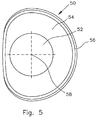
- the presentation of the Fig. 5 shows a top view of a spray nozzle according to the invention 50 according to another embodiment of the invention.
- the spray nozzle 50 is also formed as a swirl spray nozzle and has a housing with a swirl chamber 52 and an outlet channel 54, which extends from a transition between the swirl chamber 52 and the outlet channel 54 to an outlet opening 56.
- the viewer's gaze goes in Fig. 5 against the spray direction of the spray nozzle 50 in the outlet channel 54 and in the swirl chamber 52 into it.
- the outlet channel at the transition between the swirl chamber 52 and the outlet channel 54 has a circular cross-section.
- the outlet channel 54 assumes in the direction of the outlet opening 56 has a cross-sectional shape which corresponds approximately to a one-sided flattened circle.
- This shaping of the outlet channel 54 also forms a spray cone emitted by the spray nozzle 50 during operation.
- the spray nozzle 50 would create a spray of area approximately the shape of the exit orifice 56 or larger.
- Such a spray application is advantageous, for example, when the spray nozzle 50 is to be arranged close to the wall of a process chamber and it is not desirable for the wall of the process chamber to be sprayed with it.
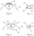
- the presentation of the Fig. 6 shows an arrangement with a conventional Doppeldrallsprühdüse 60, which has two juxtaposed outlet openings, each emitting a circular cross-section spray cone.
- the spray cones are not parallel to each other, but so far away from each other, that the central axes of the two swirl chambers diverge the spray nozzle 60 with increasing distance from the outlet openings seen in the direction of spray.
- the presentation of the Fig. 8 schematically shows the spray nozzle 10 of the invention Fig. 1 to 4 in the installed state, especially in a partially schematically illustrated gas scrubber 40 of which only a portion of its wall 66 is shown.
- the viewer's gaze goes in Fig. 4 from above into the circular cylindrical gas scrubber 40 inside.
- the spray nozzle 10 is arranged in the edge region of the scrubber 40, wherein fasteners are not shown.
- the spray nozzle 10 dispenses two spray cones, with only the resulting overlaid spray geometry 72 being shown. As has been stated, emerges from each of the outlet openings 18, 20, a spray cone with approximately elliptical shape. In the overlay then results in a spray geometry 72 with an oval cross-section.
- the cross-sectional shape of a dispensed spray geometry be it the cross-sectional shape of a single dispensed spray cone or the cross-sectional shape of two or more superimposed spray cone, can be set within wide limits. Depending on the given application and the desired in the specific application cross-sectional shape can be achieved by an optimal spray result.
- the illustrated embodiment shows a double-twist spray nozzle with two exit ports that emit sprays in the same direction.
- the invention can be seen but also be applied to other types of spray nozzles, especially to spin spray nozzles having only one outlet opening or to double-twist spray nozzles, which have two outlet openings from which spray jets emerge in opposite directions.
- the invention can also be applied to multiple spray nozzles, which have more than two outlet openings.
- the double-twist spray nozzle 10 according to the invention is according to Fig. 8 relative to the wall 66 of the process space at the same location as the spray nozzle 60 in FIG Fig. 6 arranged.
- a spray geometry 72 can be produced with the double-jet spray nozzle 10 according to the invention, which has an oval cross-sectional shape. This is achieved by the superimposition of the two spray cones generated by the double-jet spray nozzle 10. It is already in Fig. 8 to recognize that only a very small proportion 74 of the generated spray geometry 72 hits the wall 66 and thus lost.
- the spray geometry 72 with an oval cross-sectional shape has a significantly lower wall loss, since the spray geometry 72 strikes the wall 66 only in its outermost edge region.
- the spray geometry 72 strikes the wall 66 only in its outermost edge region.
- the arrangement with the conventional double-jet nozzle 60 of the 6 and 7 can be achieved by a significantly reduced wall loss and yet can be achieved with the Doppeldrallsprühdüse 10 according to the invention a large-scale coverage of the process space.
- the double-twist spray nozzle 10 according to the invention thus makes it possible to mold the spray geometry 72 output and thereby to use large spray angles without losing any of the medium sprayed on the wall 66.
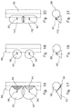
- the presentation of the Fig. 10 shows a plan view of an arrangement with two conventional double-jet spray nozzles 60.
- the double-twist spray nozzles 60 each produce two spray cones each having a circular cross-sectional shape.
- a spray geometry 76 which has approximately the shape of a twice constricted balloon in plan view. It can be seen that by the superposition of the four spray cones emitted by the double-jet spray nozzles 60 in conjunction with a large spray angle, a large area coverage by the spray geometry 76 can be achieved.
- a significant proportion 78 of the spray geometry 76 impinges on the wall 66 of the process space, which is indicated by the fraction 78 of the spray geometry 76 shown hatched.
- Fig. 11 clearly shows the dispensed spray geometry 76, which partially hits the wall 66, so that the portion 78 of the spray geometry 76 is lost and sprayed Medium from this proportion 78 can no longer be used in the process room, for example for gas purification.
- the presentation of the Fig. 12 shows an arrangement with two Doppeleldrallsprühdüsen 80 according to the invention according to another embodiment of the invention.
- the respective outlet channel and the respective outlet opening of the double-jet spray nozzles 80 according to the invention are shaped in such a way that a spray geometry 82 results in the overlay, which in the top view of FIGS Fig. 12 has the shape of a rectangle with rounded corners. It is good to see that as with the arrangement of the Fig. 10 a large coverage by the spray geometry 82 can be achieved, but that in Fig. 12 hatched portions 84 are significantly smaller than the portions 78 of the arrangement of Fig.
- Fig. 13 shows the arrangement of Fig. 12 in a side view. It can be seen that the spray geometry 82 impinges on the wall 66 of the process space only to a very small extent.
- the presentation of the Fig. 14 shows an arrangement with two Doppelsprühdüsen invention 81 according to another embodiment of the invention.
- the respective outlet channel and the respective outlet opening of the double-jet spray nozzles 81 according to the invention are shaped such that a spray geometry 83 results in the overlay.
- the spray geometry 83 is asymmetrical in that, starting from the spray nozzles 81, it extends farther to the interior of the circular wall 66 than towards the wall 66.
- Fig. 15 shows the arrangement of Fig. 14 in a side view. It can be seen that due to the non-symmetrical spray geometry 83, only a very small proportion of the drop sprays generated strike the wall 66 and that in the radial direction from the wall 66 inwards, in Fig. 15 so to the right, a large area of the process space can be covered.
- the presentation of the Fig. 16 shows an arrangement with two conventional swirl spray nozzles 86 in a plan view.
- the two swirl spray nozzles 86 each generate a spray cone with a circular cross-sectional shape.
- the vortex spray nozzles 86 are from a common manifold 88 supplied with medium to be sprayed.
- the swirl spray nozzles 86 are selected so that they have a large spray angle and thereby can apply as large a proportion of a process space as possible to the dispensed spray cone.
- Fig. 17 shows a side view of the arrangement of Fig. 16 , It will be appreciated that the portions 94 of the dispensed spray cones 92 strike the manifold conduit 88.
- Fig. 18 shows a plan view of another arrangement with two conventional Vortexsprühdüsen 96.
- the spray angle of the two Vortexsprühdüsen 96 has now been chosen smaller than in the Vorallsprühdüsen 86 of FIGS. 16 and 17 , This will, see also the side view of Fig. 19 Although avoided that the dispensed spray cone 98 hits the manifold 88. At the same time, however, it must also be accepted that the application of the spray cone 98 emitted is substantially smaller than in the case of the spray spray nozzles 86 FIGS. 16 and 17 ,
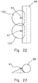
- Fig. 20 shows a plan view of an arrangement with two Sprallsprühdüsen invention 90.
- the two spin spray nozzles 90 each issue a cross-sectionally oval spray cone 102. It is based on the Fig. 20 to recognize that by the superposition of the two spray cone 102, a large-scale loading of the process space can be achieved. From the side view of Fig. 21 It can be seen that at the same time it is avoided that the dispensed spray cone 102 impinge on the manifold 88.
- the presentation of the Fig. 22 shows a plan view of an arrangement with two Sprallsprühdüsen 91 according to the invention.
- the two swirl spray nozzles 91 each issue an irregularly shaped cross-section spray cone 103.
- the spray cones 103 extend in the direction of the manifold 88 further away into the process space as in the direction of the manifold 88.
- a large-scale loading of the process space can be achieved and on the other hand is avoided, see the side view in Fig. 23 , the discharged spray cone 103 impinge on the manifold 88.
- FIG. 24 shows an arrangement of two conventional double-jet spray nozzles 104, wherein, see also the side view of Fig. 25 , each of the double-twist spray nozzles 104 outputs an upward spray cone 106 and a downward spray cone 108.
- the two double-twist spray nozzles 104 are fed from the common manifold 88.
- 108 large spray angles are selected.
- the spray cone 106 emerging upwards partly strikes the manifold 88.
- the presentation of the Fig. 26 shows a plan view of an arrangement with two conventional double-jet spray nozzles 110.
- the double-twist spray nozzles 110 respectively, see also the side view of Fig. 27 , Upwards a spray cone 112 with a small spray angle and down a spray cone 114 with a large spray angle.
- a spray cone 112 with a small spray angle and down a spray cone 114 with a large spray angle.
- the side view of the Fig. 27 Although it is prevented that the manifold 88 is sprayed through the upward spray cone 112.
- the pressurization of the process space by the spray cone 112 issued upward is comparatively small and unsatisfactory.
- the presentation of the Fig. 28 shows an arrangement with two Doppeleldrallsprühdüsen invention 100.
- the double-twist spray nozzles 100 give, see also the side view of Fig. 29 , Down each a spray cone 114 with a circular cross-section and upwards each a spray cone 116 with an oval cross-section.
- a large-area admission of the process space is achieved in the spraying direction upwards by the superposition of the two oval in cross-section spray cone 116, but at the same time it can also be ensured that the manifold 88 is not sprayed by the upward spray cone 116 issued.
- the presentation of the Fig. 30 shows an arrangement with two double-jet spray nozzles 101 according to the invention.
- Each of the double-jet spray nozzles 101 issues downwardly a spray cone 105 of circular cross section and upwards a spray cone 107 of irregularly shaped cross section.
- the irregularly shaped spray cone 107 that the process space is applied over a large area, the manifold is 88 but not hit by the upwardly discharged spray jet 107.
- the upwardly directed outlet openings of the double-jet spray nozzles 101 are for this purpose formed so that the spray jet 107 extends from the manifold 88 further away in the process chamber as in the direction of the manifold 88. This is, as explained, achieved in that the wall of the outlet opening on the, the manifold 88th facing side has a steeper angle than on the, the collecting duct 88 side facing away.
- the presentation of the Fig. 32 shows an arrangement with two conventional double-jet spray nozzles 118.
- Each of the double-twist spray nozzles 118 emits two spray cones each having a circular cross-section, wherein, as in the side view of Fig. 33 can be seen, the center axes of the swirl chambers each Doppeldrallsprühdüse 118 seen in spraying direction diverge slightly.
- the dispensed spray geometry 120 ensures a large-area coverage, but sprayed sections of the manifold 88, see also Fig. 33 ,
- Fig. 34 shows a further arrangement with two conventional double-jet spray nozzles 122, wherein compared to the double-twist spray nozzles 118 of the FIGS. 32 and 33 a smaller spray angle was chosen.
- Fig. 35 can be seen, now a spraying of the manifold 88 can be avoided, however, only a much smaller area of the process chamber with the sprayed medium is applied, as readily by comparing the FIGS. 32 and 34 or 33 and 35 can be determined.
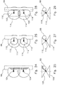
- the presentation of the Fig. 36 2 shows a plan view of an arrangement with two double-twist spray nozzles 130 according to the invention.
- Each of the double-twist spray nozzles 130 emits two spray cones, the first spray cone 132 having a circular cross section and the second spray cone 134 having an oval cross section.
- the two swirl chambers of the double-twist spray nozzles 130 are arranged at an angle to one another, so that a distance between the central axes of the two swirl chambers in the spraying direction increases.
- the resulting from the superposition of the spray jets 132, 134 resulting total spray now has an irregular shape. Due to the overlay but can be achieved, see also the side view of Fig. 37 in that a large-area loading of the process space is achieved and at the same time it is avoided that the collecting pipeline 88 is sprayed. It is in the representation of Fig. 37 to recognize that the spray cone 132, 134 penetrate and thereby the resulting, superimposed spray geometry spares the area of the manifold 88.
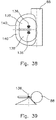
- the presentation of the Fig. 38 shows another arrangement with two Doppeleldrallsprühdüsen 136.
- Each of the double-twist spray nozzles are two spray cone in approximately the same direction down from a first spray cone 138 has a circular cross-section and a second spray cone 140 has an irregularly shaped cross-section.
- the irregularly shaped cross-section is designed such that the spray cone 140 extends from the double-twist spray nozzle 136 further into the process space, ie away from the collecting pipe, than towards the collecting pipe 88.
- the two spray jets 138 with the two spray jets 140 results in the side view of Fig. 39 illustrated spray geometry. It can be seen that the process space is covered over a large area, but the manifold 88 is not acted upon.
- An essential aspect of the invention is thus to produce a desired form of spray application by superposition of at least two spray cones, wherein at least one of the two spray cones has a non-circular cross-sectional shape.
Landscapes
- Nozzles (AREA)
Abstract
Die Erfindung betrifft eine Sprühdüse mit einem Düsengehäuse, wenigstens einer in dem Düsengehäuse angeordneten Drallkammer und wenigstens einer Austrittsöffnung, wobei die Austrittsöffnung am Ende eines Austrittskanals angeordnet ist, der von der Drallkammer ausgeht und sich in Richtung auf die Austrittsöffnung zu aufweitet, wobei am Übergang der Drallkammer in den Austrittskanal eine Engstelle angeordnet ist und wobei der Winkel der Wandung in Richtung auf die Austrittsöffnung zu stetig zunimmt oder abschnittsweise gleich bleibt, bei der ein Winkel der Wandung des Austrittskanals an der Austrittsöffnung in Umfangsrichtung der Austrittsöffnung gesehen nicht kontant ist.The invention relates to a spray nozzle with a nozzle housing, at least one arranged in the nozzle housing swirl chamber and at least one outlet opening, wherein the outlet opening is arranged at the end of an outlet channel, which starts from the swirl chamber and widening in the direction of the outlet opening, wherein at the transition of the Swirl chamber is arranged in the outlet channel a bottleneck and wherein the angle of the wall in the direction of the outlet opening to steady increases or sections remains the same, in which an angle of the wall of the outlet channel at the outlet opening in the circumferential direction of the outlet opening is not kontant.
Description
Die Erfindung betrifft eine Sprühdüse mit einem Düsengehäuse, wenigstens einer in dem Düsengehäuse angeordneten Drallkammer und wenigstens einer Austrittsöffnung, wobei die Austrittsöffnung am Ende eines Austrittskanals angeordnet ist, der von der Drallkammer ausgeht und sich in Richtung auf die Austrittsöffnung zu aufweitet, wobei eine Wandung am Übergang der Drallkammer in den Austrittskanal eine Engstelle vorgesehen ist und der Winkel der Wandung des Austrittskanals von der Engstelle aus in Richtung auf die Austrittsöffnung zu stetig zunimmt oder abschnittsweise gleich bleibt. Die Erfindung betrifft auch ein Verfahren zum Erzeugen eines Sprühkegels mit nicht runden, also von der Kreisform abweichenden Querschnitt.The invention relates to a spray nozzle having a nozzle housing, at least one arranged in the nozzle housing swirl chamber and at least one outlet opening, wherein the outlet opening is arranged at the end of an outlet channel, which starts from the swirl chamber and widens in the direction of the outlet opening, wherein a wall on Transition of the swirl chamber in the outlet channel a constriction is provided and the angle of the wall of the outlet channel from the constriction in the direction of the outlet opening increases steadily or in sections remains the same. The invention also relates to a method for producing a spray cone with non-round cross section, that is to say deviating from the circular shape.
Aus der europäischen Patentschrift
In der deutschen Patentschrift
Mit der Erfindung soll eine Sprühdüse in Bezug auf die Flexibilität ihrer Anwendung verbessert werden.The invention aims to improve a spray nozzle in terms of the flexibility of its application.
Erfindungsgemäß ist hierzu eine Sprühdüse mit einem Düsengehäuse, wenigstens einer in dem Düsengehäuse angeordneten Drallkammer und wenigstens einer Austrittsöffnung vorgesehen, wobei die Austrittsöffnung am Ende eines Austrittskanals angeordnet ist, der von der Drallkammer ausgeht und sich in Richtung auf die Austrittsöffnung zu aufweitet, wobei eine Wandung am Übergang der Drallkammer in den Austrittskanal eine Engstelle angeordnet ist und wobei der Winkel der Wandung des Austrittskanals von der Engstelle aus in Richtung auf die Austrittsöffnung zu stetig zunimmt oder abschnittsweise gleich bleibt, bei der eine Form der Austrittsöffnung von einer Kreisform abweicht und bei der ein Winkel der Wandung des Austrittskanals an der Austrittsöffnung in Umfangsrichtung der Austrittsöffnung gesehen nicht konstant ist.According to the invention for this purpose, a spray nozzle is provided with a nozzle housing, at least one arranged in the nozzle housing swirl chamber and at least one outlet opening, wherein the outlet opening is arranged at the end of an outlet channel, which starts from the swirl chamber and widens in the direction of the outlet opening, wherein a wall at the transition of the swirl chamber in the outlet channel a bottleneck is arranged and wherein the angle of the wall of the outlet channel from the constriction in the direction of the outlet opening increases continuously or in sections remains the same, in which a shape of the outlet opening deviates from a circular shape and in which an angle of the wall of the outlet channel at the outlet opening in the circumferential direction of the outlet opening is not constant.
Indem eine Form der Austrittsöffnung von einer Kreisform abweicht und ein Winkel der Wandung des Austrittskanals an der Austrittsöffnung in Umfangsrichtung der Austrittsöffnung gesehen nicht konstant ist, kann eine Querschnittsform des ausgegebenen Sprühkegels von einer Kreisform abweichen. Dies ist speziell dann vorteilhaft, wenn die räumlichen Gegebenheiten einen nicht kreisförmigen Sprühkegel ideal erscheinen lassen, um eine möglichst gute Abdeckung mit dem Sprühkegel zu erzielen. Dies kann insbesondere beispielsweise in Gaswäschern der Fall sein, wenn Sprühdüsen im Bereich der Wandung eines kreiszylinderförmigen Gaswäschers angeordnet werden. Dabei soll in der Regel verhindert werden, dass in den Gaswäscher eingesprühte Flüssigkeit von der Sprühdüse direkt auf die Wandung des Gaswäschers trifft. Mit der erfindungsgemäßen Düse kann eine von der Kreisform abweichende Querschnittsform des Sprühkegels eingestellt werden, so dass der von der Sprühdüse ausgegebene Sprühkegel sich in den Innenraum des Gaswäschers hinein und nicht in Richtung auf die Wand zu ausbreitet. Eine Engstelle zwischen Drallkammer und Austrittskanal kann durch eine umlaufende Kante und/oder einen Anfangsabschnitt des Austrittskanals gebildet sein, wobei die Wandung des Austrittkanals in diesem Anfangsabschnitt im wesentlichen parallel zu einer Mittellängsachse des Austrittskanals verläuft. Die Erfindung kann auf alle Arten von Düsen mit einer Drallkammer angewendet werden, beispielsweise Tangentialdüsen, Axialdüsen und beispielsweise auch Rücklaufdüsen. Bei Axialdüsen und Rücklaufdüsen erfolgt eine Anströmung der Drallkammer in der Regel axial, so dass gegebenenfalls ein Dralleinsatz vorgesehen ist.Since a shape of the outlet opening deviates from a circular shape and an angle of the wall of the outlet channel at the outlet opening in the circumferential direction of the outlet opening is not constant, a cross-sectional shape of the dispensed spray cone may deviate from a circular shape. This is particularly advantageous when the spatial conditions make a non-circular spray cone appear ideal in order to achieve the best possible coverage with the spray cone. This may in particular be the case, for example, in scrubbers when spray nozzles are arranged in the region of the wall of a circular-cylindrical gas scrubber. It should be prevented in the rule that sprayed into the gas scrubber liquid from the spray nozzle meets directly on the wall of the scrubber. With the nozzle according to the invention, a cross-sectional shape deviating from the circular shape of the spray cone can be adjusted, so that the spray cone emitted by the spray nozzle propagates into the interior of the scrubber and not toward the wall. A constriction between the swirl chamber and the outlet channel can be formed by a peripheral edge and / or an initial section of the outlet channel, wherein the wall of the outlet channel extends in this initial section substantially parallel to a central longitudinal axis of the outlet channel. The invention can be applied to all types of nozzles with a swirl chamber, for example tangential nozzles, axial nozzles and, for example, return nozzles. In the case of axial nozzles and return nozzles, an inflow of the swirl chamber generally takes place axially, so that a swirl insert is optionally provided.
In Weiterbildung der Erfindung weist der Austrittskanal am Übergang von der Drallkammer in den Austrittskanal einen kreisförmigen Querschnitt auf.In a development of the invention, the outlet channel has a circular cross section at the transition from the swirl chamber into the outlet channel.
Ein solcher kreisförmiger Querschnitt des Austrittskanals am Übergang von der Drallkammer in den Austrittskanal ist für eine gute Verteilung der zu versprühenden Flüssigkeit in dem ausgegebenen Sprühkegel vorteilhaft. Beispielsweise wird ein Hohlkegelspray ausgegeben. Der kreisförmige Querschnitt des Austrittskanals am Übergang von der Drallkammer in den Austrittskanal sorgt dann für eine gleichmäßige Verteilung der Flüssigkeit in dem ausgegebenen Hohlkegelspray.Such a circular cross-section of the outlet channel at the transition from the swirl chamber into the outlet channel is advantageous for a good distribution of the liquid to be sprayed in the dispensed spray cone. For example, a hollow cone spray is dispensed. The circular cross section of the outlet channel at the transition from the swirl chamber into the outlet channel then ensures a uniform distribution of the liquid in the dispensed hollow cone spray.
In Weiterbildung der Erfindung liegt der Winkel der Wandung des Austrittskanals zur Mittellängsachse des Austrittskanals an der Austrittsöffnung in einem Bereich zwischen 0° und 90°.In a further development of the invention, the angle of the wall of the outlet channel to the central longitudinal axis of the outlet channel at the outlet opening in a range between 0 ° and 90 °.
Überraschenderweise hat sich herausgestellt, dass der Winkel der Wandung des Austrittskanals an der Austrittsöffnung in einem sehr großen Bereich, nämlich zwischen 0° und 90° zur Mittellängsachse des Austrittskanals, schwanken kann und dennoch das Sprühverhalten der Sprühdüse immer noch gut ist. Speziell kann trotz des großen Winkels, in dem der Winkel der Wandung des Austrittskanals zur Mittellängsachse liegen kann, immer noch eine gute und gleichmäßige Verteilung der Flüssigkeit in dem ausgegebenen Sprühkegel erzielt werden.Surprisingly, it has been found that the angle of the wall of the outlet channel at the outlet opening in a very large area, namely between 0 ° and 90 ° to the central longitudinal axis of the outlet channel, can fluctuate and yet the spray behavior of the spray nozzle is still good. In particular, despite the large angle at which the angle of the wall of the outlet channel to the central longitudinal axis can be, still a good and uniform distribution of the liquid in the dispensed spray cone can be achieved.
In Weiterbildung der Erfindung ändert sich ein Winkel der Wandung des Austrittskanals an der Austrittsöffnung über den Umfang der Austrittsöffnung gesehen zwischen 32,5° und 65° zur Mittellängsachse des Austrittskanals.In a further development of the invention, an angle of the wall of the outlet channel at the outlet opening over the circumference of the outlet opening changes between 32.5 ° and 65 ° to the central longitudinal axis of the outlet channel.
Eine solche Bemessung der Winkeländerung der Wandung führt zur Ausbildung eines ovalen Sprühstrahls mit sehr gleichmäßiger Flüssigkeitsverteilung innerhalb des Sprühstrahls. Wird der Winkel zwischen einander gegenüberliegenden Punkten der Wandung des Austrittskanals an der Austrittsöffnung gemessen, ändert sich der Winkel der Wandung zwischen 75° und 130°.Such a dimensioning of the angle change of the wall leads to the formation of an oval spray jet with a very uniform liquid distribution within the spray jet. If the angle between opposing points of the wall of the outlet channel at the outlet opening is measured, the angle of the wall changes between 75 ° and 130 °.
In Weiterbildung der Erfindung weist die Austrittsöffnung eine ovale oder elliptische Form auf.In a further development of the invention, the outlet opening has an oval or elliptical shape.
Auf diese Weise kann einem einzelnen Sprühkegel eine ovale oder elliptische Querschnittsform verliehen werden. Durch die erfindungsgemäße Ausgestaltung der Sprühdüse ist dies bei einer guten Flüssigkeitsverteilung innerhalb des Sprühkegels möglich.In this way, a single spray cone can be given an oval or elliptical cross-sectional shape. Due to the inventive design of the spray nozzle this is possible with a good liquid distribution within the spray cone.
In Weiterbildung der Erfindung sind zwei Drallkammern und zwei Austrittsöffnungen vorgesehen, wobei die Austrittsöffnungen so angeordnet sind, dass Sprühstrahlen durch beide Austrittsöffnungen zur gleichen Seite des Gehäuses hin austreten.In a further development of the invention, two swirl chambers and two outlet openings are provided, wherein the outlet openings are arranged so that spray jets exit through both outlet openings to the same side of the housing.
In Weiterbildung der Erfindung sind zwei Drallkammern und zwei Austrittsöffnungen vorgesehen, wobei die Austrittsöffnungen so angeordnet sind, dass Sprühstrahlen durch die beiden Austrittsöffnungen zu gegenüberliegenden Seiten des Gehäuses hin austreten.In development of the invention, two swirl chambers and two outlet openings are provided, wherein the outlet openings are arranged so that spray jets escape through the two outlet openings to opposite sides of the housing.
In Weiterbildung der Erfindung wird das Düsengehäuse gegossen oder gespritzt und nachfolgend gebrannt oder gesintert.In a further development of the invention, the nozzle housing is cast or injected and subsequently fired or sintered.
Auf diese Weise können die sich ändernden Winkel der Wandung des Austrittskanals und die von der Kreisform abweichende Form der Austrittsöffnung hochpräzise und gleichzeitig wirtschaftlich realisiert werden.In this way, the changing angles of the wall of the outlet channel and deviating from the circular shape of the outlet opening can be realized with high precision and at the same time economically.
Das der Erfindung zu Grunde liegende Problem wird auch durch ein Verfahren mit den Merkmalen von Anspruch 9 gelöst.The problem underlying the invention is also solved by a method having the features of claim 9.
Weitere Merkmale und Vorteile der Erfindung ergeben sich aus den Ansprüchen und der folgenden Beschreibung einer bevorzugten Ausführungsform der Erfindung im Zusammenhang mit den Zeichnungen. In den Zeichnungen zeigen:
- Fig. 1
- eine erfindungsgemäße Sprühdüse in einer Ansicht von schräg oben,
- Fig. 2
- die Sprühdüse der
Fig. 1 von unten, - Fig. 3
- eine abschnittsweise Schnittansicht auf die Schnittebene III-III in
Fig. 1 , - Fig. 4
- eine abschnittsweise Schnittansicht auf die Schnittebene IV-IV in
Fig. 1 , - Fig. 5
- eine Draufsicht auf eine erfindungsgemäße Sprühdüse gemäß einer weiteren Ausführungsform der Erfindung,
- Fig. 6
- eine Draufsicht auf eine Anordnung mit einer konventionellen Sprühdüse,
- Fig. 7
- eine Seitenansicht der Anordnung der
Fig. 6 , - Fig. 8
- eine Draufsicht auf eine Anordnung mit einer erfindungsgemäßen Sprühdüse gemäß einer weiteren Ausführungsform,
- Fig. 9
- die Anordnung der
Fig. 8 in einer Seitenansicht, - Fig. 10
- eine Draufsicht auf eine Anordnung mit zwei konventionellen Sprühdüsen,
- Fig. 11
- eine Seitenansicht der Anordnung der
Fig. 10 , - Fig. 12
- eine Draufsicht auf eine Anordnung mit zwei erfindungsgemäßen Sprühdüsen gemäß einer weiteren Ausführungsform,
- Fig. 13
- eine Seitenansicht der Anordnung der
Fig. 12 , - Fig. 14
- eine Draufsicht auf eine Anordnung mit zwei erfindungsgemäßen Sprühdüsen gemäß einer weiterer Ausführungsform,
- Fig. 15
- eine Seitenansicht der Anordnung der
Fig. 14 , - Fig. 16
- eine Draufsicht auf eine Anordnung mit zwei konventionellen Sprühdüsen,
- Fig. 17
- eine Seitenansicht der Anordnung der
Fig. 16 , - Fig. 18
- eine Draufsicht auf eine Anordnung mit zwei konventionellen Sprühdüsen,
- Fig. 19
- eine Seitenansicht der Anordnung der
Fig. 18 , - Fig. 20
- eine Draufsicht auf eine Anordnung mit zwei erfindungsgemäßen Sprühdüsen gemäß einer weiteren Ausführungsform,
- Fig. 21
- eine Seitenansicht der Anordnung der
Fig. 20 , - Fig. 22
- eine Draufsicht auf eine Anordnung mit zwei erfindungsgemäßen Sprühdüsen gemäß einer weiteren Ausführungsform,
- Fig. 23
- eine Seitenansicht der Anordnung der
Fig. 22 , - Fig. 24
- eine Draufsicht auf eine Anordnung mit zwei konventionellen Sprühdüsen,
- Fig. 25
- die Anordnung der
Fig. 24 in einer Seitenansicht, - Fig. 26
- eine Draufsicht auf eine Anordnung mit zwei konventionellen Sprühdüsen,
- Fig. 27
- eine Seitenansicht der Anordnung der
Fig. 26 , - Fig. 28
- eine Draufsicht auf eine Anordnung mit zwei erfindungsgemäßen Sprühdüsen gemäß einer weiteren Ausführungsform,
- Fig. 29
- eine Seitenansicht der Anordnung der
Fig. 28 , - Fig. 30
- eine Draufsicht auf eine Anordnung mit zwei erfindungsgemäßen Sprühdüsen gemäß einer weiteren Ausführungsform,
- Fig. 31
- eine Seitenansicht der Anordnung der
Fig. 30 , - Fig. 32
- eine Draufsicht auf eine Anordnung mit zwei konventionellen Sprühdüsen,
- Fig. 33
- eine Seitenansicht der Anordnung der
Fig. 32 , - Fig. 34
- eine Draufsicht auf eine Anordnung mit zwei konventionellen Sprühdüsen,
- Fig. 35
- eine Seitenansicht der Anordnung der
Fig. 34 , - Fig. 36
- eine Draufsicht auf eine Anordnung mit zwei erfindungsgemäßen Sprühdüsen gemäß einer weiteren Ausführungsform,
- Fig. 37
- eine Seitenansicht der Anordnung der
Fig. 36 , - Fig. 38
- eine Draufsicht auf eine Anordnung mit zwei erfindungsgemäßen Sprühdüsen gemäß einer weiteren Ausführungsform und
- Fig. 39
- eine Seitenansicht der Anordnung der
Fig. 38 .
- Fig. 1
- a spray nozzle according to the invention in a view obliquely from above,
- Fig. 2
- the spray nozzle of the
Fig. 1 from underneath, - Fig. 3
- a sectional sectional view of the sectional plane III-III in
Fig. 1 . - Fig. 4
- a sectional sectional view on the section plane IV-IV in
Fig. 1 . - Fig. 5
- a top view of a spray nozzle according to the invention according to another embodiment of the invention,
- Fig. 6
- a top view of an arrangement with a conventional spray nozzle,
- Fig. 7
- a side view of the arrangement of
Fig. 6 . - Fig. 8
- a top view of an arrangement with a spray nozzle according to the invention according to another embodiment,
- Fig. 9
- the arrangement of
Fig. 8 in a side view, - Fig. 10
- a top view of an arrangement with two conventional spray nozzles,
- Fig. 11
- a side view of the arrangement of
Fig. 10 . - Fig. 12
- a top view of an arrangement with two spray nozzles according to the invention according to a further embodiment,
- Fig. 13
- a side view of the arrangement of
Fig. 12 . - Fig. 14
- a top view of an arrangement with two spray nozzles according to the invention according to a further embodiment,
- Fig. 15
- a side view of the arrangement of
Fig. 14 . - Fig. 16
- a top view of an arrangement with two conventional spray nozzles,
- Fig. 17
- a side view of the arrangement of
Fig. 16 . - Fig. 18
- a top view of an arrangement with two conventional spray nozzles,
- Fig. 19
- a side view of the arrangement of
Fig. 18 . - Fig. 20
- a top view of an arrangement with two spray nozzles according to the invention according to a further embodiment,
- Fig. 21
- a side view of the arrangement of
Fig. 20 . - Fig. 22
- a top view of an arrangement with two spray nozzles according to the invention according to a further embodiment,
- Fig. 23
- a side view of the arrangement of
Fig. 22 . - Fig. 24
- a top view of an arrangement with two conventional spray nozzles,
- Fig. 25
- the arrangement of
Fig. 24 in a side view, - Fig. 26
- a top view of an arrangement with two conventional spray nozzles,
- Fig. 27
- a side view of the arrangement of
Fig. 26 . - Fig. 28
- a top view of an arrangement with two spray nozzles according to the invention according to a further embodiment,
- Fig. 29
- a side view of the arrangement of
Fig. 28 . - Fig. 30
- a top view of an arrangement with two spray nozzles according to the invention according to a further embodiment,
- Fig. 31
- a side view of the arrangement of
Fig. 30 . - Fig. 32
- a top view of an arrangement with two conventional spray nozzles,
- Fig. 33
- a side view of the arrangement of
Fig. 32 . - Fig. 34
- a top view of an arrangement with two conventional spray nozzles,
- Fig. 35
- a side view of the arrangement of
Fig. 34 . - Fig. 36
- a top view of an arrangement with two spray nozzles according to the invention according to a further embodiment,
- Fig. 37
- a side view of the arrangement of
Fig. 36 . - Fig. 38
- a plan view of an arrangement with two spray nozzles according to the invention according to a further embodiment and
- Fig. 39
- a side view of the arrangement of
Fig. 38 ,
Bereits anhand der Darstellung der
Trotz der durch die schräge Anordnung leicht verzerrten Darstellung der
Indem nun die Austrittsöffnungen 20 von der Kreisform abweichen, kann den beiden ausgegebenen Sprühkegeln jeweils eine von der Kreisform abweichende Querschnittsform gegeben werden. Bei der in
Die Darstellung der
Ein in Strömungsrichtung 36 austretendes Spray, das in Einzeltropfen zerfällt, wird sich beim Durchgang durch den Austrittskanal 24 aufweiten, sobald es die Engstelle 30 passiert hat, die im wesentlichen durch die umlaufende Kante 34 gebildet ist, soweit dies die Wandung des Austrittskanals 24 zulässt. In der Schnittebene III-III wird der Sprühkegel somit die Austrittsöffnung 20 mit einem Sprühwinkel von etwas weniger als 130° verlassen.A spray emerging in the
Die Darstellung der
Ein aus dem Austrittskanal 24 austretendes Tropfenspray wird sich, sobald es die durch die Kante 34 gebildete Engstelle passiert hat und soweit dies die Wandung des Austrittskanals 24 erlaubt, bis zur Austrittsöffnung 20 hin aufweiten, so dass es an der Austrittsöffnung in der Ebene IV-IV mit einem Sprühwinkel von etwas weniger als 75° austritt.A droplet spray emerging from the
Im Ergebnis hat ein aus dem Austrittskanal 24 austretender Sprühkegel somit eine Geometrie mit einem nicht runden und bei der dargestellten Ausführungsform elliptischen Querschnitt. In der SchnittebeneIII-III, siehe
Der erhebliche Vorteil der erfindungsgemäßen Düse ist dabei, dass ein solcher, allgemein von einer Kreisform abweichender Querschnitt eines austretenden Sprühkegels alleine durch die Gestaltung der Wandung und speziell des Winkels der Wandung des Austrittskanals 24 zur Mittellängsachse 32 erzielt wird. Die Konstruktion der Drallkammer 16 sowie des Gehäuses der Düse muss dahingegen nicht geändert werden. Je nach dem erforderlichen Anwendungsfall und der gewünschten Querschnittsform des austretenden Sprühkegels kann der Austrittskanal 24 angepasst werden. Zum Erzeugen des Sprühkegels mit nicht rundem bzw. von einer Kreisform abweichendem Querschnitt wird in der Drallkammer 14, 16 ein Drall erzeugt, um Fliehkräfte auf die durchströmende Flüssigkeit zu erzeugen und diese somit in Rotation zu versetzen. Mittels der Engstelle 28, 30, die im wesentlichen durch die umlaufende Kante 34 gebildet ist und die zwischen der Drallkammer 14, 16 und dem Austrittskanal 22, 24 liegt, wird der Volumenstrom durch die Düse gedrosselt und eingestellt. Die durch die Kante 34 und den nachfolgenden Beginn des Austrittskanals 22, 24 gebildete Verjüngung ist dabei so ausgebildet, dass die durchströmende Flüssigkeit gleichmäßig auf den Umfang dieser Engstelle verteilt ist. Hier spielt der in der Drallkammer erzeugte Drall und die somit in der Drallkammer rotierende Flüssigkeit eine wichtige Rolle. Im Austrittskanal 22, 24 wird dann der nicht runde Sprühkegel durch die nicht rotationssymmetrisch aufgebaute Wandung des Austrittskanals geformt. Durch unterschiedliche Steigungen bzw. unterschiedliche Winkel wird bis hin zur Austrittsöffnung 18, 20 der Abflugwinkel der Tropfen individuell vorgegeben. Je nach dem, in welchem Wandabschnitt sich Tropfen befinden und welchen Winkel zur Mittelachse dieser Wandabschnitt einnimmt, wird der Abflugwinkel der Tropfen vorgegeben und im Ergebnis wird dadurch ein Sprühkegel mit nicht rundem Querschnitt geformt.The considerable advantage of the nozzle according to the invention is that such, generally deviating from a circular cross-section of an exiting spray cone alone by the design of the wall and especially the angle of the wall of the
Bei Düsen aus Keramikwerkstoffen oder Sinterwerkstoffen ermöglicht dies ein sehr flexibles Herstellungsverfahren. Das Düsengehäuse 12 mit den beiden Drallkammern und dem Anschluss 26 kann immer mittels derselben Formen hergestellt werden. Lediglich die Düsenmündungen, also die Austrittskanäle 22, 24, werden je nach dem gewünschten Anwendungsfall geändert. Hierzu können dann abgeänderte Formen verwendet werden. Eine Keramikmasse wird somit in die gewünschte Form gebracht und anschließend gebrannt. Auf diese Weise lassen sich vergleichsweise einfach und kostengünstig Düsen mit unterschiedlichen Querschnittsformen der ausgegebenen Sprühstrahlen herstellen. In analoger Weise kann entsprechend bei Düsen vorgegangen werden, die aus Sinterwerkstoffen hergestellt werden. Hier wird beispielsweise ein Metallpulver mit einem Kunststoffbinder vermischt, in eine Form gespritzt und anschließend gesintert, um dann eine aus metallischem Sinterwerkstoff bestehende Düse zu erhalten. Die erfindungsgemäße Sprühdüse kann aber beispielsweise auch aus Kunststoff oder Metall gegossen, im Schichtaufbau hergestellt oder auch mechanisch mittels spanabhebender Verfahren gefertigt werden.For nozzles made of ceramic materials or sintered materials, this allows a very flexible manufacturing process. The
Ein erheblicher Vorteil der erfindungsgemäßen Düse ist, dass durch die Beibehaltung der Form der Drallkammern und auch der Kreisform des Austrittskanals am Beginn der Austrittskanäle 22, 24 eine gleichmäßige Verteilung der Flüssigkeit in den ausgegebenen Sprühstrahlen gewährleistet werden kann. Lediglich die Querschnittsform der Sprühstrahlen wird durch die Gestaltung der Austrittskanäle und die Form der Austrittsöffnungen 18, 20 verändert.A significant advantage of the nozzle according to the invention is that by maintaining the shape of the swirl chambers and also the circular shape of the outlet channel at the beginning of the
Die Darstellung der
Zu erkennen ist, dass der Austrittskanal am Übergang zwischen der Drallkammer 52 und dem Austrittskanal 54 einen kreisförmigen Querschnitt hat. Im weiteren Verlauf des Austrittskanals 54 zu der Austrittsöffnung 56 hin verändert sich der Querschnitt des Austrittskanals 54, der sich in dieser Richtung auch erweitert. Der Austrittskanal 54 nimmt in Richtung zur Austrittsöffnung 56 eine Querschnittsform an, die etwa einem einseitig abgeplatteten Kreis entspricht. Durch diese Formgebung des Austrittskanals 54 wird auch ein im Betrieb von der Sprühdüse 50 ausgegebener Sprühkegel geformt. Auf einer ebenen Fläche, die senkrecht zu einer Mittelachse 58 der Drallkammer 52 liegt, würde die Sprühdüse 50 eine Sprühbeaufschlagung mit einer Fläche erzeugen, die etwa die Form der Austrittsöffnung 56 hat oder größer ist. Eine solche Sprühbeaufschlagung ist beispielsweise dann vorteilhaft, wenn die Sprühdüse 50 nahe an der Wand eines Prozessraums angeordnet werden soll und es nicht erwünscht ist, dass die Wand des Prozessraums mitbesprüht wird.It can be seen that the outlet channel at the transition between the
Die Darstellung der
Dadurch ergibt sich in der Überlagerung der beiden Sprühkegel eine Sprühgeometrie 62, die eine in der Mitte eingeschnürte Form hat. Besonders nachteilig ist aber, dass ein in
Dies ist auch in der Seitenansicht der
Die Darstellung der
Mit der erfindungsgemäßen Sprühdüse kann die Querschnittsform einer ausgegebenen Sprühgeometrie, sei es die Querschnittsform eines einzelnen ausgegebenen Sprühkegels oder die Querschnittsform zweier oder mehrerer überlagerter Sprühkegel, in weiten Grenzen eingestellt werden. Je nach dem gegebenen Anwendungsfall und der in dem speziellen Anwendungsfall gewünschten Querschnittsform kann dadurch ein optimales Sprühergebnis erzielt werden.With the spray nozzle according to the invention, the cross-sectional shape of a dispensed spray geometry, be it the cross-sectional shape of a single dispensed spray cone or the cross-sectional shape of two or more superimposed spray cone, can be set within wide limits. Depending on the given application and the desired in the specific application cross-sectional shape can be achieved by an optimal spray result.
Die dargestellte Ausführungsform zeigt eine Doppeldrallsprühdüse mit zwei Austrittsöffnungen, die Sprühstrahlen in die gleiche Richtung ausgeben. Die Erfindung kann ersichtlich aber auch auf andere Arten von Sprühdüsen angewendet werden, speziell auf Drallsprühdüsen, die lediglich eine Austrittsöffnung aufweisen oder auf Doppeldrallsprühdüsen, die zwei Austrittsöffnungen haben, aus denen Sprühstrahlen in entgegengesetzten Richtungen austreten. Die Erfindung kann auch Mehrfachsprühdüsen angewendet werden, die mehr als zwei Austrittsöffnungen haben.The illustrated embodiment shows a double-twist spray nozzle with two exit ports that emit sprays in the same direction. The invention can be seen but also be applied to other types of spray nozzles, especially to spin spray nozzles having only one outlet opening or to double-twist spray nozzles, which have two outlet openings from which spray jets emerge in opposite directions. The invention can also be applied to multiple spray nozzles, which have more than two outlet openings.
Die erfindungsgemäße Doppeldrallsprühdüse 10 ist gemäß
Dies ist auch in der Seitenansicht der
Die erfindungsgemäße Doppeldrallsprühdüse 10 ermöglicht es also, die ausgegebene Sprühgeometrie 72 zu formen und dadurch große Sprühwinkel zu verwenden, ohne an der Wand 66 versprühtes Medium ungenutzt zu verlieren.The double-
Die Darstellung der
Die Seitenansicht der
Die Darstellung der
Die Seitenansicht der
Die Darstellung der
Die Ansicht der
Die Darstellung der
Dies hat aber zur Folge, dass ein in
Die Darstellung der
Die Darstellung der
Die Darstellung der
Die beiden Doppeldrallsprühdüsen 104 werden aus der gemeinsamen Sammelrohrleitung 88 gespeist. Um eine großflächige Beaufschlagung durch die Sprühkegel 106, 108 zu erzielen, werden große Sprühwinkel gewählt. In der Seitenansicht der
Die Darstellung der
Die Darstellung der
Die Darstellung der
Die Darstellung der
Die Darstellung der
Die beiden Drallkammern der Doppeldrallsprühdüsen 130 sind in einem Winkel zueinander angeordnet, so dass sich ein Abstand zwischen den Mittelachsen der beiden Drallkammern in Sprührichtung gesehen vergrößert.The two swirl chambers of the double-
Der sich aus der Überlagerung der Sprühstrahlen 132, 134 ergebende Gesamtsprühstrahl weist nun eine unregelmäßige Form auf. Durch die Überlagerung kann aber erreicht werden, siehe auch die Seitenansicht der
Die Darstellung der
Ein wesentlicher Aspekt der Erfindung liegt somit darin, eine gewünschte Form einer Sprühbeaufschlagung durch Überlagerung von mindestens zwei Sprühkegeln zu erzeugen, wobei wenigstens einer der beiden Sprühkegel eine nicht kreisrunde Querschnittsform aufweist.An essential aspect of the invention is thus to produce a desired form of spray application by superposition of at least two spray cones, wherein at least one of the two spray cones has a non-circular cross-sectional shape.
Claims (10)
wobei mittels der Engstelle die zu versprühende Flüssigkeit gleichmäßig auf den Umfang der Engstelle verteilt wird,
whereby by means of the constriction the liquid to be sprayed is evenly distributed over the circumference of the constriction,
Applications Claiming Priority (1)
| Application Number | Priority Date | Filing Date | Title |
|---|---|---|---|
| DE102015207741.1A DE102015207741A1 (en) | 2015-04-28 | 2015-04-28 | spray nozzle |
Publications (2)
| Publication Number | Publication Date |
|---|---|
| EP3088087A1 true EP3088087A1 (en) | 2016-11-02 |
| EP3088087B1 EP3088087B1 (en) | 2019-10-23 |
Family
ID=55808417
Family Applications (1)
| Application Number | Title | Priority Date | Filing Date |
|---|---|---|---|
| EP16166257.2A Active EP3088087B1 (en) | 2015-04-28 | 2016-04-20 | Spray nozzle and method for producing non-round spray cones |
Country Status (5)
| Country | Link |
|---|---|
| US (1) | US9925546B2 (en) |
| EP (1) | EP3088087B1 (en) |
| CN (1) | CN106076683B (en) |
| DE (1) | DE102015207741A1 (en) |
| HU (1) | HUE046880T2 (en) |
Families Citing this family (3)
| Publication number | Priority date | Publication date | Assignee | Title |
|---|---|---|---|---|
| EP3793653B1 (en) * | 2018-05-14 | 2023-10-25 | Covidien LP | Systems and methods for ventilation humidification |
| CN111804460B (en) * | 2020-07-22 | 2021-05-28 | 南通市广益机电有限责任公司 | Fog gun machine |
| CN113350932B (en) * | 2021-05-31 | 2022-11-04 | 周辰晓 | Constructional engineering is with spraying dust device |
Citations (7)
| Publication number | Priority date | Publication date | Assignee | Title |
|---|---|---|---|---|
| FR2372057A1 (en) * | 1976-11-30 | 1978-06-23 | Bosch Gmbh Robert | DEVICE FOR WASHING THE GLASSES OF AUTOMOBILE HEADLIGHTS |
| US5622489A (en) * | 1995-04-13 | 1997-04-22 | Monro; Richard J. | Fuel atomizer and apparatus and method for reducing NOx |
| US20010010341A1 (en) * | 2000-01-27 | 2001-08-02 | Aisan Kogyo Kabushiki Kaisha | Fuel injection valve |
| DE10033781C1 (en) | 2000-07-12 | 2001-12-06 | Lechler Gmbh & Co Kg | Dual rotation spray jet has common feed channel leading tangentially to opposing rotation chambers on either side of its center axis |
| EP1491260B1 (en) | 2003-06-21 | 2005-08-10 | Lechler GmbH | Double swirl nozzle |
| CN201172011Y (en) * | 2008-01-15 | 2008-12-31 | 陈美青 | Spray head of dust remover |
| WO2013028165A2 (en) * | 2011-08-22 | 2013-02-28 | Spraying Systems Co. | Multiple whirl spray nozzle |
Family Cites Families (28)
| Publication number | Priority date | Publication date | Assignee | Title |
|---|---|---|---|---|
| US545320A (en) * | 1895-08-27 | Lawn-sprinkler or irrigator | ||
| AT21837B (en) | 1904-07-09 | 1905-10-25 | Erich Neumann | Automatic photographic time and moment lock. |
| US1668271A (en) * | 1926-08-09 | 1928-05-01 | Charles R Fisk | Sprinkler |
| US1780233A (en) * | 1928-07-12 | 1930-11-04 | Jenkins Howard | Sprinkler |
| US1961408A (en) * | 1932-05-28 | 1934-06-05 | Binks Mfg Co | Spray head |
| US2484577A (en) * | 1945-03-29 | 1949-10-11 | Monarch Mfg Works Inc | Double orifice solid cone spray nozzle |
| US3326473A (en) * | 1964-08-07 | 1967-06-20 | Spraying Systems Co | Spray nozzle |
| FR1562357A (en) * | 1967-03-23 | 1969-04-04 | ||
| DE1655022A1 (en) * | 1967-03-23 | 1971-03-25 | Seifert Gerd W Dr Ing | Spray device for windshield washer systems, especially for windshields of motor vehicles |
| DE1655048A1 (en) * | 1967-06-05 | 1971-07-15 | Seifert Gerd W Dr Ing | Spray device for windscreen washer systems |
| US3771728A (en) * | 1971-03-17 | 1973-11-13 | F Polnauer | Spray nozzles with spiral flow of fluid and method of constructing the same |
| US3948444A (en) * | 1973-11-12 | 1976-04-06 | Delavan Manufacturing Co. | Low drift spray method |
| US3923253A (en) * | 1974-05-21 | 1975-12-02 | Grefco | Spraying nozzle |
| US4664314A (en) * | 1982-10-01 | 1987-05-12 | Spraying Systems Co. | Whirl spray nozzle |
| FR2546080B1 (en) | 1983-05-20 | 1987-02-13 | Fives Cail Babcock | ATOMIZATION NOZZLE |
| DE3407706C2 (en) * | 1984-03-02 | 1987-02-05 | Gottfried Bischoff Bau kompl. Gasreinigungs- und Wasserrückkühlanlagen GmbH & Co KG, 4300 Essen | Swirl nozzle, especially for flue gas scrubbing towers |
| DE4015412C1 (en) * | 1990-05-14 | 1991-06-20 | Lothar 3300 Braunschweig De Clavey | Metal work deburring tool - has sonde inserted into bore to discharge high pressure water |
| JP2579028Y2 (en) | 1992-09-09 | 1998-08-20 | 株式会社いけうち | nozzle |
| JPH0788531A (en) | 1993-09-22 | 1995-04-04 | Nkk Corp | Spray nozzle |
| JPH07163915A (en) | 1993-12-14 | 1995-06-27 | Ikeuchi:Kk | Spay nozzle |
| JP3494327B2 (en) | 1995-10-03 | 2004-02-09 | 株式会社共立合金製作所 | Descaler nozzle |
| DE19758526B4 (en) * | 1997-08-23 | 2004-07-15 | Lechler Gmbh + Co. Kg | Drallsprühdüse |
| DK1047504T3 (en) * | 1997-11-14 | 2002-02-18 | Concast Standard Ag | Slot nozzle for spraying a strand cast product with a coolant |
| DE19918257A1 (en) | 1999-04-22 | 2000-11-23 | Lechler Gmbh & Co Kg | High pressure spray nozzle |
| FI111870B (en) | 2002-01-15 | 2003-09-30 | Metso Paper Inc | Munstycksserie |
| FR2888762B1 (en) * | 2005-07-22 | 2008-05-02 | Rexam Dispensing Systems Sas | NOZZLE DRIVES DIVERGENT |
| DE102005047195B3 (en) * | 2005-09-23 | 2007-06-06 | Lechler Gmbh | Solid cone spray nozzle |
| DE102007024221B4 (en) * | 2007-05-15 | 2011-06-16 | Lechler Gmbh | Method for producing a high pressure spray nozzle and high pressure spray nozzle |
-
2015
- 2015-04-28 DE DE102015207741.1A patent/DE102015207741A1/en not_active Withdrawn
-
2016
- 2016-04-20 HU HUE16166257A patent/HUE046880T2/en unknown
- 2016-04-20 EP EP16166257.2A patent/EP3088087B1/en active Active
- 2016-04-27 US US15/139,912 patent/US9925546B2/en active Active
- 2016-04-28 CN CN201610271674.4A patent/CN106076683B/en active Active
Patent Citations (7)
| Publication number | Priority date | Publication date | Assignee | Title |
|---|---|---|---|---|
| FR2372057A1 (en) * | 1976-11-30 | 1978-06-23 | Bosch Gmbh Robert | DEVICE FOR WASHING THE GLASSES OF AUTOMOBILE HEADLIGHTS |
| US5622489A (en) * | 1995-04-13 | 1997-04-22 | Monro; Richard J. | Fuel atomizer and apparatus and method for reducing NOx |
| US20010010341A1 (en) * | 2000-01-27 | 2001-08-02 | Aisan Kogyo Kabushiki Kaisha | Fuel injection valve |
| DE10033781C1 (en) | 2000-07-12 | 2001-12-06 | Lechler Gmbh & Co Kg | Dual rotation spray jet has common feed channel leading tangentially to opposing rotation chambers on either side of its center axis |
| EP1491260B1 (en) | 2003-06-21 | 2005-08-10 | Lechler GmbH | Double swirl nozzle |
| CN201172011Y (en) * | 2008-01-15 | 2008-12-31 | 陈美青 | Spray head of dust remover |
| WO2013028165A2 (en) * | 2011-08-22 | 2013-02-28 | Spraying Systems Co. | Multiple whirl spray nozzle |
Also Published As
| Publication number | Publication date |
|---|---|
| US9925546B2 (en) | 2018-03-27 |
| DE102015207741A1 (en) | 2016-11-03 |
| CN106076683A (en) | 2016-11-09 |
| HUE046880T2 (en) | 2020-03-30 |
| US20160318047A1 (en) | 2016-11-03 |
| CN106076683B (en) | 2019-11-26 |
| EP3088087B1 (en) | 2019-10-23 |
Similar Documents
| Publication | Publication Date | Title |
|---|---|---|
| EP1767277B1 (en) | Solid cone spray nozzle | |
| DE102007024247B3 (en) | High pressure nozzle and method of making a high pressure nozzle | |
| EP2576079B1 (en) | Nozzle head for a spray gun | |
| EP1986788B1 (en) | Two-component nozzle with secondary air nozzles arranged in circular form | |
| EP2969234B1 (en) | Atomizer nozzle for a sanitary water outlet and sanitary outlet fitting with a water outlet | |
| EP3069794B1 (en) | Flat-jet nozzle and use of a flat-jet nozzle | |
| DE112012005017B4 (en) | Apparatus for controlling fluid flow in an emergency washing system, apparatus for controlling fluid flow and washing system for providing fluid flow | |
| EP3318336B1 (en) | Filter jet aligner unit and high pressure nozzle unit | |
| DE10303858A1 (en) | Fuel injector assembly with induced turbulence | |
| EP2403698B1 (en) | Apparatus for producing plastic parts interspersed with reinforcing fibres | |
| EP2879805B1 (en) | Nozzle arrangement | |
| DE3116660A1 (en) | "AIR SPRAYER SPRAY NOZZLE" | |
| EP3042724B1 (en) | Method for generating a spray jet and dual material nozzle | |
| EP3088087B1 (en) | Spray nozzle and method for producing non-round spray cones | |
| DE19623713B4 (en) | Injection valve, in particular for the direct injection of fuel into a combustion chamber of an internal combustion engine | |
| WO2016055116A1 (en) | Pneumatic atomizing nozzle | |
| DE19931890A1 (en) | Edge rounding method for combustion engine fuel injection nozzle injection orifice channel | |
| EP2931434B1 (en) | Fan nozzle | |
| DE3706694A1 (en) | TWO-MATERIAL SPRAYING NOZZLE FOR GENERATING A FULL-CONE JET | |
| DE69913442T2 (en) | Fluid atomizer | |
| DE102011102693B4 (en) | Extinguishing nozzle head with flow channel | |
| EP2186572A1 (en) | Ring split nozzle | |
| EP3935230B1 (en) | Aerator | |
| DE102013220917A1 (en) | injection | |
| DE102013002235B4 (en) | Air suction device for a sanitary shower |
Legal Events
| Date | Code | Title | Description |
|---|---|---|---|
| PUAI | Public reference made under article 153(3) epc to a published international application that has entered the european phase |
Free format text: ORIGINAL CODE: 0009012 |
|
| AK | Designated contracting states |
Kind code of ref document: A1 Designated state(s): AL AT BE BG CH CY CZ DE DK EE ES FI FR GB GR HR HU IE IS IT LI LT LU LV MC MK MT NL NO PL PT RO RS SE SI SK SM TR |
|
| AX | Request for extension of the european patent |
Extension state: BA ME |
|
| STAA | Information on the status of an ep patent application or granted ep patent |
Free format text: STATUS: REQUEST FOR EXAMINATION WAS MADE |
|
| 17P | Request for examination filed |
Effective date: 20170329 |
|
| RBV | Designated contracting states (corrected) |
Designated state(s): AL AT BE BG CH CY CZ DE DK EE ES FI FR GB GR HR HU IE IS IT LI LT LU LV MC MK MT NL NO PL PT RO RS SE SI SK SM TR |
|
| STAA | Information on the status of an ep patent application or granted ep patent |
Free format text: STATUS: EXAMINATION IS IN PROGRESS |
|
| 17Q | First examination report despatched |
Effective date: 20190102 |
|
| GRAP | Despatch of communication of intention to grant a patent |
Free format text: ORIGINAL CODE: EPIDOSNIGR1 |
|
| STAA | Information on the status of an ep patent application or granted ep patent |
Free format text: STATUS: GRANT OF PATENT IS INTENDED |
|
| RIC1 | Information provided on ipc code assigned before grant |
Ipc: B05B 1/34 20060101ALI20190528BHEP Ipc: B05B 1/06 20060101ALN20190528BHEP Ipc: B05B 1/02 20060101AFI20190528BHEP Ipc: B05B 1/14 20060101ALI20190528BHEP Ipc: B05B 12/16 20180101ALI20190528BHEP |
|
| INTG | Intention to grant announced |
Effective date: 20190702 |
|
| GRAS | Grant fee paid |
Free format text: ORIGINAL CODE: EPIDOSNIGR3 |
|
| GRAA | (expected) grant |
Free format text: ORIGINAL CODE: 0009210 |
|
| STAA | Information on the status of an ep patent application or granted ep patent |
Free format text: STATUS: THE PATENT HAS BEEN GRANTED |
|
| AK | Designated contracting states |
Kind code of ref document: B1 Designated state(s): AL AT BE BG CH CY CZ DE DK EE ES FI FR GB GR HR HU IE IS IT LI LT LU LV MC MK MT NL NO PL PT RO RS SE SI SK SM TR |
|
| REG | Reference to a national code |
Ref country code: GB Ref legal event code: FG4D Free format text: NOT ENGLISH |
|
| REG | Reference to a national code |
Ref country code: CH Ref legal event code: EP |
|
| REG | Reference to a national code |
Ref country code: IE Ref legal event code: FG4D Free format text: LANGUAGE OF EP DOCUMENT: GERMAN |
|
| REG | Reference to a national code |
Ref country code: DE Ref legal event code: R096 Ref document number: 502016007184 Country of ref document: DE |
|
| REG | Reference to a national code |
Ref country code: AT Ref legal event code: REF Ref document number: 1193088 Country of ref document: AT Kind code of ref document: T Effective date: 20191115 |
|
| REG | Reference to a national code |
Ref country code: NL Ref legal event code: MP Effective date: 20191023 |
|
| REG | Reference to a national code |
Ref country code: LT Ref legal event code: MG4D |
|
| REG | Reference to a national code |
Ref country code: HU Ref legal event code: AG4A Ref document number: E046880 Country of ref document: HU |
|
| PG25 | Lapsed in a contracting state [announced via postgrant information from national office to epo] |
Ref country code: PT Free format text: LAPSE BECAUSE OF FAILURE TO SUBMIT A TRANSLATION OF THE DESCRIPTION OR TO PAY THE FEE WITHIN THE PRESCRIBED TIME-LIMIT Effective date: 20200224 Ref country code: FI Free format text: LAPSE BECAUSE OF FAILURE TO SUBMIT A TRANSLATION OF THE DESCRIPTION OR TO PAY THE FEE WITHIN THE PRESCRIBED TIME-LIMIT Effective date: 20191023 Ref country code: BG Free format text: LAPSE BECAUSE OF FAILURE TO SUBMIT A TRANSLATION OF THE DESCRIPTION OR TO PAY THE FEE WITHIN THE PRESCRIBED TIME-LIMIT Effective date: 20200123 Ref country code: GR Free format text: LAPSE BECAUSE OF FAILURE TO SUBMIT A TRANSLATION OF THE DESCRIPTION OR TO PAY THE FEE WITHIN THE PRESCRIBED TIME-LIMIT Effective date: 20200124 Ref country code: SE Free format text: LAPSE BECAUSE OF FAILURE TO SUBMIT A TRANSLATION OF THE DESCRIPTION OR TO PAY THE FEE WITHIN THE PRESCRIBED TIME-LIMIT Effective date: 20191023 Ref country code: NO Free format text: LAPSE BECAUSE OF FAILURE TO SUBMIT A TRANSLATION OF THE DESCRIPTION OR TO PAY THE FEE WITHIN THE PRESCRIBED TIME-LIMIT Effective date: 20200123 Ref country code: LV Free format text: LAPSE BECAUSE OF FAILURE TO SUBMIT A TRANSLATION OF THE DESCRIPTION OR TO PAY THE FEE WITHIN THE PRESCRIBED TIME-LIMIT Effective date: 20191023 Ref country code: PL Free format text: LAPSE BECAUSE OF FAILURE TO SUBMIT A TRANSLATION OF THE DESCRIPTION OR TO PAY THE FEE WITHIN THE PRESCRIBED TIME-LIMIT Effective date: 20191023 Ref country code: NL Free format text: LAPSE BECAUSE OF FAILURE TO SUBMIT A TRANSLATION OF THE DESCRIPTION OR TO PAY THE FEE WITHIN THE PRESCRIBED TIME-LIMIT Effective date: 20191023 Ref country code: LT Free format text: LAPSE BECAUSE OF FAILURE TO SUBMIT A TRANSLATION OF THE DESCRIPTION OR TO PAY THE FEE WITHIN THE PRESCRIBED TIME-LIMIT Effective date: 20191023 |
|
| PG25 | Lapsed in a contracting state [announced via postgrant information from national office to epo] |
Ref country code: HR Free format text: LAPSE BECAUSE OF FAILURE TO SUBMIT A TRANSLATION OF THE DESCRIPTION OR TO PAY THE FEE WITHIN THE PRESCRIBED TIME-LIMIT Effective date: 20191023 Ref country code: RS Free format text: LAPSE BECAUSE OF FAILURE TO SUBMIT A TRANSLATION OF THE DESCRIPTION OR TO PAY THE FEE WITHIN THE PRESCRIBED TIME-LIMIT Effective date: 20191023 Ref country code: IS Free format text: LAPSE BECAUSE OF FAILURE TO SUBMIT A TRANSLATION OF THE DESCRIPTION OR TO PAY THE FEE WITHIN THE PRESCRIBED TIME-LIMIT Effective date: 20200224 |
|
| PG25 | Lapsed in a contracting state [announced via postgrant information from national office to epo] |
Ref country code: AL Free format text: LAPSE BECAUSE OF FAILURE TO SUBMIT A TRANSLATION OF THE DESCRIPTION OR TO PAY THE FEE WITHIN THE PRESCRIBED TIME-LIMIT Effective date: 20191023 |
|
| REG | Reference to a national code |
Ref country code: DE Ref legal event code: R097 Ref document number: 502016007184 Country of ref document: DE |
|
| PG2D | Information on lapse in contracting state deleted |
Ref country code: IS |
|
| PG25 | Lapsed in a contracting state [announced via postgrant information from national office to epo] |
Ref country code: EE Free format text: LAPSE BECAUSE OF FAILURE TO SUBMIT A TRANSLATION OF THE DESCRIPTION OR TO PAY THE FEE WITHIN THE PRESCRIBED TIME-LIMIT Effective date: 20191023 Ref country code: DK Free format text: LAPSE BECAUSE OF FAILURE TO SUBMIT A TRANSLATION OF THE DESCRIPTION OR TO PAY THE FEE WITHIN THE PRESCRIBED TIME-LIMIT Effective date: 20191023 Ref country code: RO Free format text: LAPSE BECAUSE OF FAILURE TO SUBMIT A TRANSLATION OF THE DESCRIPTION OR TO PAY THE FEE WITHIN THE PRESCRIBED TIME-LIMIT Effective date: 20191023 Ref country code: ES Free format text: LAPSE BECAUSE OF FAILURE TO SUBMIT A TRANSLATION OF THE DESCRIPTION OR TO PAY THE FEE WITHIN THE PRESCRIBED TIME-LIMIT Effective date: 20191023 Ref country code: IS Free format text: LAPSE BECAUSE OF FAILURE TO SUBMIT A TRANSLATION OF THE DESCRIPTION OR TO PAY THE FEE WITHIN THE PRESCRIBED TIME-LIMIT Effective date: 20200223 |
|
| PLBE | No opposition filed within time limit |
Free format text: ORIGINAL CODE: 0009261 |
|
| STAA | Information on the status of an ep patent application or granted ep patent |
Free format text: STATUS: NO OPPOSITION FILED WITHIN TIME LIMIT |
|
| PG25 | Lapsed in a contracting state [announced via postgrant information from national office to epo] |
Ref country code: IT Free format text: LAPSE BECAUSE OF FAILURE TO SUBMIT A TRANSLATION OF THE DESCRIPTION OR TO PAY THE FEE WITHIN THE PRESCRIBED TIME-LIMIT Effective date: 20191023 Ref country code: SM Free format text: LAPSE BECAUSE OF FAILURE TO SUBMIT A TRANSLATION OF THE DESCRIPTION OR TO PAY THE FEE WITHIN THE PRESCRIBED TIME-LIMIT Effective date: 20191023 Ref country code: SK Free format text: LAPSE BECAUSE OF FAILURE TO SUBMIT A TRANSLATION OF THE DESCRIPTION OR TO PAY THE FEE WITHIN THE PRESCRIBED TIME-LIMIT Effective date: 20191023 |
|
| 26N | No opposition filed |
Effective date: 20200724 |
|
| PG25 | Lapsed in a contracting state [announced via postgrant information from national office to epo] |
Ref country code: MC Free format text: LAPSE BECAUSE OF FAILURE TO SUBMIT A TRANSLATION OF THE DESCRIPTION OR TO PAY THE FEE WITHIN THE PRESCRIBED TIME-LIMIT Effective date: 20191023 Ref country code: SI Free format text: LAPSE BECAUSE OF FAILURE TO SUBMIT A TRANSLATION OF THE DESCRIPTION OR TO PAY THE FEE WITHIN THE PRESCRIBED TIME-LIMIT Effective date: 20191023 |
|
| REG | Reference to a national code |
Ref country code: CH Ref legal event code: PL |
|
| PG25 | Lapsed in a contracting state [announced via postgrant information from national office to epo] |
Ref country code: LI Free format text: LAPSE BECAUSE OF NON-PAYMENT OF DUE FEES Effective date: 20200430 Ref country code: CH Free format text: LAPSE BECAUSE OF NON-PAYMENT OF DUE FEES Effective date: 20200430 Ref country code: LU Free format text: LAPSE BECAUSE OF NON-PAYMENT OF DUE FEES Effective date: 20200420 Ref country code: FR Free format text: LAPSE BECAUSE OF NON-PAYMENT OF DUE FEES Effective date: 20200430 |
|
| REG | Reference to a national code |
Ref country code: BE Ref legal event code: MM Effective date: 20200430 |
|
| PG25 | Lapsed in a contracting state [announced via postgrant information from national office to epo] |
Ref country code: BE Free format text: LAPSE BECAUSE OF NON-PAYMENT OF DUE FEES Effective date: 20200430 |
|
| GBPC | Gb: european patent ceased through non-payment of renewal fee |
Effective date: 20200420 |
|
| PG25 | Lapsed in a contracting state [announced via postgrant information from national office to epo] |
Ref country code: IE Free format text: LAPSE BECAUSE OF NON-PAYMENT OF DUE FEES Effective date: 20200420 Ref country code: GB Free format text: LAPSE BECAUSE OF NON-PAYMENT OF DUE FEES Effective date: 20200420 |
|
| PG25 | Lapsed in a contracting state [announced via postgrant information from national office to epo] |
Ref country code: TR Free format text: LAPSE BECAUSE OF FAILURE TO SUBMIT A TRANSLATION OF THE DESCRIPTION OR TO PAY THE FEE WITHIN THE PRESCRIBED TIME-LIMIT Effective date: 20191023 Ref country code: MT Free format text: LAPSE BECAUSE OF FAILURE TO SUBMIT A TRANSLATION OF THE DESCRIPTION OR TO PAY THE FEE WITHIN THE PRESCRIBED TIME-LIMIT Effective date: 20191023 Ref country code: CY Free format text: LAPSE BECAUSE OF FAILURE TO SUBMIT A TRANSLATION OF THE DESCRIPTION OR TO PAY THE FEE WITHIN THE PRESCRIBED TIME-LIMIT Effective date: 20191023 |
|
| REG | Reference to a national code |
Ref country code: AT Ref legal event code: MM01 Ref document number: 1193088 Country of ref document: AT Kind code of ref document: T Effective date: 20210420 |
|
| PG25 | Lapsed in a contracting state [announced via postgrant information from national office to epo] |
Ref country code: MK Free format text: LAPSE BECAUSE OF FAILURE TO SUBMIT A TRANSLATION OF THE DESCRIPTION OR TO PAY THE FEE WITHIN THE PRESCRIBED TIME-LIMIT Effective date: 20191023 |
|
| PG25 | Lapsed in a contracting state [announced via postgrant information from national office to epo] |
Ref country code: AT Free format text: LAPSE BECAUSE OF NON-PAYMENT OF DUE FEES Effective date: 20210420 |
|
| PGFP | Annual fee paid to national office [announced via postgrant information from national office to epo] |
Ref country code: DE Payment date: 20230420 Year of fee payment: 8 |
|
| PGFP | Annual fee paid to national office [announced via postgrant information from national office to epo] |
Ref country code: CZ Payment date: 20240405 Year of fee payment: 9 |
|
| PGFP | Annual fee paid to national office [announced via postgrant information from national office to epo] |
Ref country code: HU Payment date: 20240419 Year of fee payment: 9 |