EP2969234B1 - Atomizer nozzle for a sanitary water outlet and sanitary outlet fitting with a water outlet - Google Patents
Atomizer nozzle for a sanitary water outlet and sanitary outlet fitting with a water outlet Download PDFInfo
- Publication number
- EP2969234B1 EP2969234B1 EP14700966.6A EP14700966A EP2969234B1 EP 2969234 B1 EP2969234 B1 EP 2969234B1 EP 14700966 A EP14700966 A EP 14700966A EP 2969234 B1 EP2969234 B1 EP 2969234B1
- Authority
- EP
- European Patent Office
- Prior art keywords
- nozzle
- atomiser
- channel
- water outlet
- outlet
- Prior art date
- Legal status (The legal status is an assumption and is not a legal conclusion. Google has not performed a legal analysis and makes no representation as to the accuracy of the status listed.)
- Active
Links
Images


Classifications
-
- B—PERFORMING OPERATIONS; TRANSPORTING
- B05—SPRAYING OR ATOMISING IN GENERAL; APPLYING FLUENT MATERIALS TO SURFACES, IN GENERAL
- B05B—SPRAYING APPARATUS; ATOMISING APPARATUS; NOZZLES
- B05B1/00—Nozzles, spray heads or other outlets, with or without auxiliary devices such as valves, heating means
- B05B1/34—Nozzles, spray heads or other outlets, with or without auxiliary devices such as valves, heating means designed to influence the nature of flow of the liquid or other fluent material, e.g. to produce swirl
- B05B1/3405—Nozzles, spray heads or other outlets, with or without auxiliary devices such as valves, heating means designed to influence the nature of flow of the liquid or other fluent material, e.g. to produce swirl to produce swirl
- B05B1/341—Nozzles, spray heads or other outlets, with or without auxiliary devices such as valves, heating means designed to influence the nature of flow of the liquid or other fluent material, e.g. to produce swirl to produce swirl before discharging the liquid or other fluent material, e.g. in a swirl chamber upstream the spray outlet
- B05B1/3421—Nozzles, spray heads or other outlets, with or without auxiliary devices such as valves, heating means designed to influence the nature of flow of the liquid or other fluent material, e.g. to produce swirl to produce swirl before discharging the liquid or other fluent material, e.g. in a swirl chamber upstream the spray outlet with channels emerging substantially tangentially in the swirl chamber
- B05B1/3431—Nozzles, spray heads or other outlets, with or without auxiliary devices such as valves, heating means designed to influence the nature of flow of the liquid or other fluent material, e.g. to produce swirl to produce swirl before discharging the liquid or other fluent material, e.g. in a swirl chamber upstream the spray outlet with channels emerging substantially tangentially in the swirl chamber the channels being formed at the interface of cooperating elements, e.g. by means of grooves
- B05B1/3436—Nozzles, spray heads or other outlets, with or without auxiliary devices such as valves, heating means designed to influence the nature of flow of the liquid or other fluent material, e.g. to produce swirl to produce swirl before discharging the liquid or other fluent material, e.g. in a swirl chamber upstream the spray outlet with channels emerging substantially tangentially in the swirl chamber the channels being formed at the interface of cooperating elements, e.g. by means of grooves the interface being a plane perpendicular to the outlet axis
-
- B—PERFORMING OPERATIONS; TRANSPORTING
- B05—SPRAYING OR ATOMISING IN GENERAL; APPLYING FLUENT MATERIALS TO SURFACES, IN GENERAL
- B05B—SPRAYING APPARATUS; ATOMISING APPARATUS; NOZZLES
- B05B1/00—Nozzles, spray heads or other outlets, with or without auxiliary devices such as valves, heating means
- B05B1/02—Nozzles, spray heads or other outlets, with or without auxiliary devices such as valves, heating means designed to produce a jet, spray, or other discharge of particular shape or nature, e.g. in single drops, or having an outlet of particular shape
- B05B1/06—Nozzles, spray heads or other outlets, with or without auxiliary devices such as valves, heating means designed to produce a jet, spray, or other discharge of particular shape or nature, e.g. in single drops, or having an outlet of particular shape in annular, tubular or hollow conical form
-
- B—PERFORMING OPERATIONS; TRANSPORTING
- B05—SPRAYING OR ATOMISING IN GENERAL; APPLYING FLUENT MATERIALS TO SURFACES, IN GENERAL
- B05B—SPRAYING APPARATUS; ATOMISING APPARATUS; NOZZLES
- B05B1/00—Nozzles, spray heads or other outlets, with or without auxiliary devices such as valves, heating means
- B05B1/14—Nozzles, spray heads or other outlets, with or without auxiliary devices such as valves, heating means with multiple outlet openings; with strainers in or outside the outlet opening
- B05B1/18—Roses; Shower heads
- B05B1/185—Roses; Shower heads characterised by their outlet element; Mounting arrangements therefor
-
- E—FIXED CONSTRUCTIONS
- E03—WATER SUPPLY; SEWERAGE
- E03C—DOMESTIC PLUMBING INSTALLATIONS FOR FRESH WATER OR WASTE WATER; SINKS
- E03C1/00—Domestic plumbing installations for fresh water or waste water; Sinks
- E03C1/02—Plumbing installations for fresh water
- E03C1/04—Water-basin installations specially adapted to wash-basins or baths
- E03C1/0408—Water installations especially for showers
- E03C1/0409—Shower handles
-
- E—FIXED CONSTRUCTIONS
- E03—WATER SUPPLY; SEWERAGE
- E03C—DOMESTIC PLUMBING INSTALLATIONS FOR FRESH WATER OR WASTE WATER; SINKS
- E03C1/00—Domestic plumbing installations for fresh water or waste water; Sinks
- E03C1/02—Plumbing installations for fresh water
- E03C1/08—Jet regulators or jet guides, e.g. anti-splash devices
Definitions
- the present invention relates to a spray nozzle for a sanitary water spout, for atomizing pressurized water, which atomizer nozzle has a swirl chamber in which at least one oriented transversely to the nozzle longitudinal axis and tangentially into the swirl chamber feed channel, each supply channel at least one inlet channel upstream in the flow direction and wherein the swirl chamber tapers in the outflow direction in the direction of a nozzle channel at the Kanalend Scheme the water jet exits into the atmosphere.
- the invention also relates to a sanitary outlet fitting with a water outlet, which has at least one atomizer nozzle of the type mentioned.
- a device for spraying a pressurized liquid which can serve as a mouthpiece of a sanitary outlet fitting or shower head.
- the prior art device has a central liquid supply passage extending along the device axis. At a distance around the device axis around a plurality of vortex chambers are provided, each having an inlet for supplying the liquid into the respective vortex chamber and an outlet nozzle for the exit of a liquid jet from the vortex chamber.
- the swirl chambers are connected to the supply channel via inlet channels, which are arranged substantially transversely to the device axis.
- Each of the outlet nozzles is arranged obliquely to the longitudinal axis of the device so that liquid jets emerging from the outlet nozzles in a predetermined Distance from the outlet nozzles meet.
- the previously known device can be used advantageously wherever a good cleaning performance is desired with a low volume flow.
- the previously known device has a comparatively complex structure, which can complicate the manufacture of the device.
- the spray pattern of the emerging from the prior art device water jet is still in need of improvement.
- a spray nozzle of the type mentioned for a sanitary water spout for atomizing pressurized water is known.
- the atomizer nozzle has a circular swirl chamber, into which a feed channel oriented transversely to the nozzle longitudinal axis and tangentially enters the swirl chamber, wherein each feed channel is preceded by at least one inlet channel in the flow direction and wherein the swirl chamber tapers in the outflow direction to a nozzle channel Kanalend Scheme the water jet in the atmosphere exits.
- the structure of this prior art atomizer nozzle is also relatively complex, which may for example make it difficult to manufacture the atomizer nozzle.
- the jet pattern of the exiting water jet is still in need of improvement.
- the atomizer nozzle according to the invention is intended for a sanitary water spout to atomize a pressurized water and thereby to form a homogeneous jet of water.
- the atomizer nozzle according to the invention has a swirl chamber in which at least one feed channel oriented transversely to the nozzle longitudinal axis and entering the swirl chamber tangentially opens, such that the water flowing in the swirl chamber experiences a swirl about the swirl chamber longitudinal axis.
- the swirl chamber tapers in the outflow direction toward a nozzle channel, so that in the swirl chamber in rotation about the swirl chamber longitudinal axis staggered water jet is merged into smaller and smaller circular paths through the nozzle channel, until the water jet at the Kanalend Scheme the nozzle channel into the atmosphere emerges where forms a fluid slat, which bursts at its free peripheral edge area in such fine individual droplets that a homogeneous and formed from fine water droplets water jet is formed.
- the atomizer nozzle has a nozzle body which has an inlet-side insertion opening, that at least one groove intended for forming an inlet channel is provided on the peripheral wall of the insertion opening, that a stopper into the insertion opening up to an annular shoulder encircling the inner circumference can be used, which annular shoulder has at least one provided for forming a feed channel groove, and that the plug forms the plug facing channel wall of the inlet and feed channels.
- the atomizer nozzle according to the invention has it a nozzle body having an inflow-side insertion opening. At least one groove, which is intended to form an inlet channel, is provided on the peripheral wall of the insertion opening.
- the plug can be used up to an inner circumferential circumferential annular shoulder, which annular shoulder is interrupted by at least one groove which is intended to form a feed channel. After insertion of the plug in the inflow-side insertion opening of the nozzle body, the plug is on the outside of the grooves so that this plug forms the plug facing the channel wall of the inlet and feed channels.
- This embodiment of the atomizer nozzle according to the invention the production thereof is substantially simplified.
- a preferred embodiment according to the invention provides that the swirl chamber has the shape of a funnel in the direction of the nozzle channel.
- a particularly advantageous embodiment according to the invention provides that the swirl chamber has the shape, in particular, of a conical or rotationally hyperbolic funnel.
- a preferred embodiment according to the invention provides that in the swirl chamber protrudes a central and oriented in the nozzle longitudinal direction projection.
- the projecting into the swirl chamber projection favors that along the swirl chamber wall in a rotational movement offset water jet can not escape into the chamber center of the swirl chamber.
- the incoming from several feed channels Water flows can not influence each other and can swirl uncontrollably, it is advantageous if the projection projects beyond a plane formed by the mouth openings of the feed channels in the direction of the nozzle channel.
- the projection is provided on the swirl chamber facing end side of the plug.
- the at least one inlet channel of each feed channel is oriented in the longitudinal direction of the nozzle.
- each inlet channel is preceded by an inlet channel oriented in the longitudinal direction of the nozzle in the flow direction.
- the jet pattern of the water jet emerging from the atomizer nozzle according to the invention is additionally improved if the atomizer nozzle has a plurality of feed channels distributed preferably at uniform intervals in the circumferential direction.
- a preferred embodiment according to the invention provides that the atomizer nozzle is designed as a hollow cone nozzle.
- the water flowing in from the line network flows tangentially into the swirl chamber of the atomizer nozzle designed as a hollow cone nozzle, whereby a fluid vortex arises there.
- the water flowing in circular paths through the nozzle channel forms a lamella at the outflow-side channel end region of the nozzle channel, which lumps at its end edge into individual droplets.
- the outflow-side channel end region of the nozzle channel has a cross-sectional widening that widens in the direction of the outflow end and preferably has a spherical configuration.
- the solution according to the invention is that its water outlet at least one atomizer nozzle according to claims 1 to 8.
- the water outlet is designed as a shower head or as a jet regulator.
- a preferred embodiment according to the invention provides that the outlet designed as a jet outlet water outlet is mounted on a sanitary outlet fitting.
- the water outlet has at least two atomizer nozzles, which are arranged distributed over the cross section of the water outlet.
- the preparation of the outlet fitting in the region of its water outlet is substantially simplified if the water outlet has a housing or a body, and if at least one insertion opening is provided in the housing or the body into which the nozzle body of a spray nozzle is preferably detachably insertable.
- the jet regulator is preceded by an attachment or filter screen and if the attachment or filter screen on the inflow side jet regulator end face preferably releasably attachable.
- the water outlet carries at least three atomizer nozzles and if the atomizer nozzles are arranged on a preferably concentric to the shower head longitudinal axis circular path or in a linear array.
- a linear arrangement of the atomizer nozzles is suitable, for example, if the atomizer nozzles are to be arranged star-shaped relative to one another or if the atomizer nozzles are to be arranged in a rectangular water outlet in at least one line-shaped arrangement relative to one another.
- the water emerging from the atomizer nozzles initially has the shape of a hollow cone, which is formed by a circular circumferential water wall.
- a hollow cone which is formed by a circular circumferential water wall.
- the nozzle longitudinal axes of the atomizer nozzles are inclined to each other such that emerging from the nozzle liquid jets in a predetermined Distance from the nozzles meet.
- a preferred embodiment according to the invention provides that the nozzle longitudinal axes of the atomizer nozzles are arranged at an angle of 1 degree to 10 degrees to the longitudinal axis of the water outlet and in particular to its housing longitudinal axis.
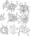
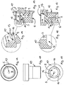
- a spray nozzle 1 is shown, which is intended for a sanitary water spout for atomizing pressurized water.
- the atomizing nozzle 1 should nevertheless form a voluminous homogeneous stream of water from a small volume flow.
- the atomizer nozzle 1 has a swirl chamber 2 which on the inflow side has a chamber section 3 which is essentially cylindrical or disk-shaped in the clear cross section.
- the swirl chamber 2 opens at least one transverse and preferably oriented at right angles to the longitudinal axis of the nozzle and tangentially in the swirl chamber 2 incoming feed 4.
- the swirl chamber 2 tapers in the outflow direction in a funnel shape in the direction of a nozzle channel 5, which nozzle channel 5 at its outflow-side channel end region has a cross-sectional widening 6 widening in the direction of the outflow end, which is designed to be spherical or rounded here.
- the funnel-shaped section 9 of the swirl chamber is designed in its clear cross section so that the swirl chamber in the direction of the nozzle channel 5 has the shape of a conical or rotationally hyperbolic funnel.
- the flowing out of the channel openings of the feed channels 4 water flows can not affect unfavorably, is in the swirl chamber 2 before a central and oriented in the nozzle longitudinal direction projection 8 before. As in FIG. 8 can be seen, this projection 8 projects beyond a through the mouth openings of the feed channels 4 imaginary plane in the direction of the nozzle channel 5.
- the atomizer nozzle 1 shown here has a nozzle body 10 which has an inflow-side insertion opening 11. On the peripheral wall of the insertion opening 11 is at least one intended to form an inlet channel groove 12 is provided. In this case, each feed channel 4 is preceded by an inlet channel 13 oriented in the longitudinal direction of the nozzle in the flow direction.
- a plug 14 can be used up to a circumferentially encircling annular shoulder 15.
- the annular shoulder 15 is interrupted by at least one groove 16, which is provided to form a feed channel 4.
- the outer periphery of the plug 14 closes the at least one groove 12 to an inlet channel 13, the end face of the plug 14 closes the at least one groove 16 to a feed channel 4.
- the projection 8 is provided at the swirl chamber 2 facing end face of the plug 14, the projection 8 is provided.
- the atomizer nozzle 1 has a plurality of feed channels and here three feed channels 4, which are distributed in the circumferential direction at regular intervals from each other.
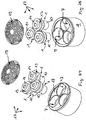
- FIGS. 17 to 25 is shown as a water outlet of a not shown here sanitary outlet fitting certain jet regulator 17, the more of the in FIGS. 1 to 16 having atomizer nozzles 1 shown.
- the in the FIGS. 17 to 25 shown jet regulator 17 has at least two, and preferably three atomizing nozzles 1, which are arranged distributed over the cross section of serving as a water outlet jet regulator 17.
- the jet regulator 17 has a housing 18, in which at least one insertion opening 7 is provided, into which the nozzle body 10 of a spray nozzle 1 is preferably detachably insertable.
- the jet regulator 17 is preceded by a header or filter screen 19.
- This attachment or filter screen 19 is here preferably releasably attachable to the inflow-side jet regulator end face.
- FIG. 23 It can be seen that the nozzle longitudinal axes of the atomizer nozzles 1 provided in the jet regulator 17 are inclined relative to one another such that liquid jets emerging from the nozzles meet at a predetermined distance from the nozzles.
- the atomizer nozzles 1 define a nozzle longitudinal axis extending at an angle of 1 to 10 degrees to the longitudinal axis of the jet regulator 17 and in particular to its housing longitudinal axis.
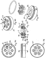
- FIGS. 26 and 27 is designed as a hand shower 20 trained sanitary outlet fitting whose water outlet is designed as a shower head 21.
- the in the FIGS. 28 to 32 shown shower head 21 has at least two atomizer nozzles 1, which are arranged distributed over the cross section of the shower head 21.
- the shower head 21 has a housing or body 22, in which at least one insertion opening 23 is provided into which the nozzle body 10 of a spray nozzle 1 is preferably detachably insertable.
- more than three and in particular six atomizing nozzles 1 are provided, which are arranged on a circular path which extends concentrically to the shower head longitudinal axis.
- the nozzle longitudinal axes of the atomizer nozzles 1 provided in the shower head 21 are also inclined relative to one another such that liquid jets emerging from the nozzles meet at a predetermined distance from the nozzles.
- the nozzle longitudinal axes of the atomizer nozzles 1 define a longitudinal axis of the nozzle designed as a shower head 21 at an angle of 1 degree to 10 degrees to the longitudinal axis and in particular to the longitudinal axis of its body 22 extending nozzle longitudinal axis.
- the water exits in a spray cone of 15 degrees to 40 degrees. This forms a fluid lamella, which bursts at its free outline or end edge in individual droplets.
- These fluid droplets of the effluent from the atomizer 1 water unite to one over the entire beam cross-section homogeneous overall jet, which, despite its comparatively low flow rate, gives the impression of a voluminous water jet with the usual cleaning power.
- atomizer nozzle 1 allows the modular design of the specific for a sanitary outlet fitting water outlet. Although the water passing through the atomizing nozzle 1 emerges as a hollow cone there, the oblique arrangement of a plurality of atomizing nozzles nevertheless forms a homogeneous water jet formed over the entire beam cross section of fine water droplets. From the FIGS. 2, 6, 7 and 8 It can be seen that the inflow-side edge region of the nozzle body has a nozzle body section 24 which widens against the inflow direction and which can form a solid sealing lip after the nozzle body has been inserted into the housing 18 or the body 22 of a water outlet.
- This formed by the portion 24 sealing lip combines a sealing function and a holding function in itself, which holds the nozzle body 10 practically barb-like manner in the housing 18 or in the body 22 of the water outlet.
- the nozzle channel 5 should have at its opening into the atmosphere channel opening a Düsenabrisskante 25, which has an angle equal to or less than 90 degrees in order to achieve the best possible atomization in the spray nozzle 1.
- At least one preferably circumferential sealing and / or holding claw 26 is provided on the stopper 14, which holds this stopper 14 in the insertion opening 11 of the nozzle body 10.
- preferably formed with a constant cross section portion 27 of the nozzle channel 5 is comparatively long and a length of at least 1/3 of the length of the nozzle body, preferably a length of 1/3 to 1/2 of the length of the nozzle body 10, having. Over the length of the nozzle channel 5 and its designed with constant cross-section 27, the length of the spray cone formed by the spray nozzle 1 can be determined and bundle the effluent water jet in addition. The individual components of the spray nozzle 1 can be produced inexpensively and reliably.
- the feed and inlet channels 4, 13 have a comparatively small cross-section, these components of the atomizer nozzle 1 can be manufactured with little effort and with sufficient precision.
- the atomizer nozzle 1 shown here allows the production of a water outlet, which facilitates a minimum water consumption and still allows a good and full-surface water wetting by means of the exiting water jet even at low pressures, for example 2 to 3 bar.
Description
Die vorliegende Erfindung betrifft eine Zerstäuberdüse für einen sanitären Wasserauslauf, zum Zerstäuben von unter Druck stehendem Wasser, welche Zerstäuberdüse eine Drallkammer hat, in der zumindest ein quer zur Düsen-Längsachse orientierter und tangential in die Drallkammer einlaufender Zuführkanal mündet, wobei jedem Zuführkanal wenigstens ein Einlaufkanal in Strömungsrichtung vorgeschaltet ist und wobei sich die Drallkammer in Abströmrichtung in Richtung zu einem Düsenkanal verjüngt, an dessen Kanalendbereich der Wasserstrahl in die Atmosphäre austritt.The present invention relates to a spray nozzle for a sanitary water spout, for atomizing pressurized water, which atomizer nozzle has a swirl chamber in which at least one oriented transversely to the nozzle longitudinal axis and tangentially into the swirl chamber feed channel, each supply channel at least one inlet channel upstream in the flow direction and wherein the swirl chamber tapers in the outflow direction in the direction of a nozzle channel at the Kanalendbereich the water jet exits into the atmosphere.
Die Erfindung befasst sich auch mit einer sanitären Auslaufarmaturmit einem Wasserauslauf, der zumindest eine Zerstäuberdüse der eingangs erwähnten Art aufweist hat.The invention also relates to a sanitary outlet fitting with a water outlet, which has at least one atomizer nozzle of the type mentioned.
Aus der
Aus der
Es besteht daher die Aufgabe, eine Zerstäuberdüse der eingangs erwähnten Art zu schaffen, die mit geringem Aufwand herstellbar ist und die sich durch ein homogenes Strahlbild des austretenden Wasserstrahls auszeichnet. Darüber hinaus besteht auch die Aufgabe, eine sanitäre Auslaufarmatur mit einem Wasserauslauf zu schaffen, die bezüglich ihres Wasserauslaufs mit geringem Aufwand herstellbar ist und die sich durch ein homogenes Strahlbild des austretenden Wasserstrahls auszeichnet.It is therefore an object to provide an atomizer nozzle of the type mentioned, which can be produced with little effort and which is characterized by a homogeneous jet pattern of the exiting water jet. In addition, there is also the task of creating a sanitary outlet fitting with a water outlet, which can be produced with little effort with respect to their water outlet and which is characterized by a homogeneous jet pattern of the exiting water jet.
Die erfindungsgemäße Lösung dieser Aufgabe besteht bei der Zerstäuberdüse der eingangs erwähnten Art in den Merkmalen des geltenden Anspruchs 1.The achievement of this object is in the atomizer nozzle of the type mentioned in the features of the current claim. 1
Die Merkmale des Oberbegriffs des Anspruchs 1 sind aus dem Dokument
Die erfindungsgemäße Zerstäuberdüse ist für einen sanitären Wasserauslauf bestimmt, um ein unter Druck stehendes Wasser zu zerstäuben und dadurch zu einem homogenen Wasserstrahl zu formen. Die erfindungsgemäße Zerstäuberdüse weist eine Drallkammer auf, in der zumindest ein quer zur Düsen-Längsachse orientierter und derart tangential in die Drallkammer einlaufender Zuführkanal mündet, dass das in der Drallkammer einströmende Wasser einen Drall um die Drallkammer-Längsachse erfährt. Die Drallkammer verjüngt sich in Abströmrichtung in Richtung zu einem Düsenkanal, so dass der in der Drallkammer in Rotation um die Drallkammer-Längsachse versetzte Wasserstrahl in immer kleineren Kreisbahnen zusammengeführt und durch den Düsenkanal geleitet wird, bis der Wasserstrahl an dem Kanalendbereich des Düsenkanals in die Atmosphäre austritt, wo sich eine Fluid-Lamelle ausbildet, die an ihrem freien Umfangsrandbereich in derart feine Einzeltröpfchen zerplatzt, dass ein homogener und aus feinen Wassertröpfchen gebildeter Wasserstrahl entsteht. Bei der erfindungsgemäßen Zerstäuberdüse ist vorgesehen, dass die Zerstäuberdüse einen Düsenkorpus hat, der eine zuströmseitige Einsetzöffnung aufweist, dass an der Umfangswand der Einsetzöffnung wenigstens eine, zur Bildung eines Einlaufkanals bestimmte Nut vorgesehen ist, dass in die Einsetzöffnung ein Stopfen bis zu einem innenumfangsseitig umlaufenden Ringabsatz einsetzbar ist, welcher Ringabsatz mindestens eine zur Bildung eines Zuführkanales vorgesehene Nut aufweist, und dass der Stopfen die dem Stopfen zugewandte Kanalwand der Einlauf- und Zuführkanäle bildet. Die erfindungsgemäße Zerstäuberdüse weist damit einen Düsenkorpus auf, der eine zuströmseitige Einsetzöffnung hat. An der Umfangswand der Einsetzöffnung ist wenigstens eine Nut vorgesehen, die zur Bildung eines Einlaufkanals bestimmt ist. Der Stopfen ist bis zu einem innenumfangsseitig umlaufenden Ringabsatz einsetzbar, welcher Ringabsatz durch mindestens eine Nut unterbrochen ist, die zur Bildung eines Zuführkanales bestimmt ist. Nach dem Einsetzen des Stopfens in die zuströmseitige Einsetzöffnung des Düsenkorpus liegt der Stopfen außenseitig derart an den Nuten an, dass dieser Stopfen die dem Stopfen zugewandte Kanalwand der Einlauf- und Zuführkanäle bildet. Durch diese Ausgestaltung der erfindungsgemäßen Zerstäuberdüse wird deren Herstellung wesentlich vereinfacht.The atomizer nozzle according to the invention is intended for a sanitary water spout to atomize a pressurized water and thereby to form a homogeneous jet of water. The atomizer nozzle according to the invention has a swirl chamber in which at least one feed channel oriented transversely to the nozzle longitudinal axis and entering the swirl chamber tangentially opens, such that the water flowing in the swirl chamber experiences a swirl about the swirl chamber longitudinal axis. The swirl chamber tapers in the outflow direction toward a nozzle channel, so that in the swirl chamber in rotation about the swirl chamber longitudinal axis staggered water jet is merged into smaller and smaller circular paths through the nozzle channel, until the water jet at the Kanalendbereich the nozzle channel into the atmosphere emerges where forms a fluid slat, which bursts at its free peripheral edge area in such fine individual droplets that a homogeneous and formed from fine water droplets water jet is formed. In the case of the atomizer nozzle according to the invention, it is provided that the atomizer nozzle has a nozzle body which has an inlet-side insertion opening, that at least one groove intended for forming an inlet channel is provided on the peripheral wall of the insertion opening, that a stopper into the insertion opening up to an annular shoulder encircling the inner circumference can be used, which annular shoulder has at least one provided for forming a feed channel groove, and that the plug forms the plug facing channel wall of the inlet and feed channels. The atomizer nozzle according to the invention has it a nozzle body having an inflow-side insertion opening. At least one groove, which is intended to form an inlet channel, is provided on the peripheral wall of the insertion opening. The plug can be used up to an inner circumferential circumferential annular shoulder, which annular shoulder is interrupted by at least one groove which is intended to form a feed channel. After insertion of the plug in the inflow-side insertion opening of the nozzle body, the plug is on the outside of the grooves so that this plug forms the plug facing the channel wall of the inlet and feed channels. This embodiment of the atomizer nozzle according to the invention, the production thereof is substantially simplified.
Damit der in der Drallkammer in eine Rotation um die Drallkammer-Längsachse versetzte Wasserstrom in Richtung zum Düsenkanal in immer kleiner werdenden Kreisbahnen zusammengeführt werden kann, sieht eine bevorzugte Ausführungsform gemäß der Erfindung vor, dass die Drallkammer in Richtung zum Düsenkanal die Form eines Trichters aufweist. Dabei sieht eine besonders vorteilhafte Ausführungsform gemäß der Erfindung vor, dass die Drallkammer die Form insbesondere eines kegeligen oder rotationshyperbolischen Trichters hat.So that the water flow staggered in the swirl chamber into a rotation about the swirl chamber longitudinal axis can be brought together in ever smaller circular paths in the direction of the nozzle channel, a preferred embodiment according to the invention provides that the swirl chamber has the shape of a funnel in the direction of the nozzle channel. In this case, a particularly advantageous embodiment according to the invention provides that the swirl chamber has the shape, in particular, of a conical or rotationally hyperbolic funnel.
Eine bevorzugte Ausführungsform gemäß der Erfindung sieht vor, dass in die Drallkammer ein zentraler und in Düsen-Längsrichtung orientierter Vorsprung vorsteht. Der in die Drallkammer vorstehende Vorsprung begünstigt, dass der entlang der Drallkammerwandung in eine Rotationsbewegung versetzte Wasserstrahl nicht in das Kammer-Zentrum der Drallkammer ausweichen kann.A preferred embodiment according to the invention provides that in the swirl chamber protrudes a central and oriented in the nozzle longitudinal direction projection. The projecting into the swirl chamber projection favors that along the swirl chamber wall in a rotational movement offset water jet can not escape into the chamber center of the swirl chamber.
Damit sich insbesondere die aus mehreren Zuführkanälen zuströmenden Wasserströme nicht gegenseitig beeinflussen und unkontrolliert verwirbeln können, ist es vorteilhaft, wenn der Vorsprung über eine durch die Mündungsöffnungen der Zuführkanäle gedachte Ebene in Richtung zum Düsenkanal vorsteht.Thus, in particular, the incoming from several feed channels Water flows can not influence each other and can swirl uncontrollably, it is advantageous if the projection projects beyond a plane formed by the mouth openings of the feed channels in the direction of the nozzle channel.
Dabei ist es besonders vorteilhaft, wenn an der der Drallkammer zugewandten Stirnseite des Stopfens der Vorsprung vorgesehen ist.It is particularly advantageous if the projection is provided on the swirl chamber facing end side of the plug.
Um die Herstellung und Konstruktion der erfindungsgemäßen Zerstäuberdüse noch zusätzlich zu vereinfachen, ist es vorteilhaft, wenn der wenigstens eine Einlaufkanal eines jeden Zuführkanals in Düsen-Längsrichtung orientiert ist.To further simplify the production and construction of the atomizer nozzle according to the invention, it is advantageous if the at least one inlet channel of each feed channel is oriented in the longitudinal direction of the nozzle.
Um das vom Wasserversorgungsnetz kommende Wasser auf einfache Weise an den wenigstens einen, quer zur Düsen-Längsachse orientierten Zuführkanal führen zu können, ist es vorteilhaft, wenn jedem Zuführkanal ein in Düsen-Längsrichtung orientierter Einlaufkanal in Strömungsrichtung vorgeschaltet ist.In order to be able to easily guide the water coming from the water supply network to the at least one feed channel oriented transversely to the longitudinal axis of the nozzle, it is advantageous if each inlet channel is preceded by an inlet channel oriented in the longitudinal direction of the nozzle in the flow direction.
Das Strahlbild des aus der erfindungsgemäßen Zerstäuberdüse austretenden Wasserstrahls wird noch zusätzlich verbessert, wenn die Zerstäuberdüse mehrere in Umfangsrichtung vorzugsweise in gleichmäßigen Abständen verteilte Zuführkanäle hat.The jet pattern of the water jet emerging from the atomizer nozzle according to the invention is additionally improved if the atomizer nozzle has a plurality of feed channels distributed preferably at uniform intervals in the circumferential direction.
Eine bevorzugte Ausführungsform gemäß der Erfindung sieht vor, dass die Zerstäuberdüse als Hohlkegeldüse ausgestaltet ist. Das vom Leitungsnetz her zuströmende Wasser strömt tangential in die Drallkammer der als Hohlkegeldüse ausgestalteten Zerstäuberdüse ein, wodurch dort ein Fluidwirbel entsteht. Das in Kreisbahnen durch den Düsenkanal durchströmende Wasser bildet am ausströmseitigen Kanalendbereich des Düsenkanals eine Lamelle aus, die an ihrer Endkante in Einzel-Tröpfchen zerplatzt.A preferred embodiment according to the invention provides that the atomizer nozzle is designed as a hollow cone nozzle. The water flowing in from the line network flows tangentially into the swirl chamber of the atomizer nozzle designed as a hollow cone nozzle, whereby a fluid vortex arises there. The water flowing in circular paths through the nozzle channel forms a lamella at the outflow-side channel end region of the nozzle channel, which lumps at its end edge into individual droplets.
Um das als Hohlkegel ausströmende Wasser gut formen zu können, ist es zweckmäßig, wenn der ausströmseitige Kanalendbereich des Düsenkanals eine in Richtung zum Ausströmende hin sich erweiternde und vorzugsweise kugelig ausgestaltete Querschnittserweiterung aufweist.In order to be able to shape the water flowing out as a hollow cone, it is expedient if the outflow-side channel end region of the nozzle channel has a cross-sectional widening that widens in the direction of the outflow end and preferably has a spherical configuration.
Bei der Auslaufarmatur der eingangs erwähnten Art besteht die erfindungsgemäße Lösung darin, dass ihr Wasserauslauf zumindest eine Zerstäuberdüse gemäß den Ansprüchen 1 bis 8 aufweist.In the outlet fitting of the type mentioned above, the solution according to the invention is that its water outlet at least one atomizer nozzle according to
Dabei sehen bevorzugte Anwendungsbeispiele gemäß der Erfindung vor, dass der Wasserauslauf als Brausekopf oder als Strahlregler ausgebildet ist.Here, preferred application examples according to the invention provide that the water outlet is designed as a shower head or as a jet regulator.
Eine bevorzugte Ausführungsform gemäß der Erfindung sieht vor, dass der als Strahlregler ausgebildete Wasserauslauf ausströmseitig an einer sanitären Auslaufarmatur montierbar ist.A preferred embodiment according to the invention provides that the outlet designed as a jet outlet water outlet is mounted on a sanitary outlet fitting.
Um aus der sanitären Auslaufarmatur einen Wasserstrahl auszuströmen zu lassen, der trotz des vergleichsweise geringen Volumenstroms einen ausreichend breiten Strahlquerschnitt hat, ist es vorteilhaft, wenn der Wasserauslauf zumindest zwei Zerstäuberdüsen aufweist, die über den Querschnitt des Wasserauslaufs verteilt angeordnet sind.In order to let flow out of the sanitary outlet fitting a water jet, which despite the comparatively low volume flow has a sufficiently wide beam cross-section, it is advantageous if the water outlet has at least two atomizer nozzles, which are arranged distributed over the cross section of the water outlet.
Die Herstellung der Auslaufarmatur im Bereich ihres Wasserauslaufs wird wesentlich vereinfacht, wenn der Wasserauslauf ein Gehäuse oder ein Korpus hat, und wenn in dem Gehäuse oder dem Korpus wenigstens eine Einsetzöffnung vorgesehen ist, in die der Düsenkorpus einer Zerstäuberdüse vorzugsweise lösbar einsetzbar ist.The preparation of the outlet fitting in the region of its water outlet is substantially simplified if the water outlet has a housing or a body, and if at least one insertion opening is provided in the housing or the body into which the nozzle body of a spray nozzle is preferably detachably insertable.
Um die im Wasser eventuell mitgeführten Schmutzpartikel ausfiltern zu können, bevor solche Schmutzpartikel die Funktion der im Wasserauslauf vorgesehen Zerstäuberdüsen beeinträchtigen, ist es vorteilhaft, wenn dem Strahlregler ein Vorsatz- oder Filtersieb vorgeschaltet ist und wenn das Vorsatz- oder Filtersieb an der zuströmseitigen Strahlregler-Stirnseite vorzugsweise lösbar befestigbar ist.To be able to filter out the dirt particles possibly entrained in the water before such dirt particles impair the function of the atomizer nozzles provided in the water outlet, it is advantageous if the jet regulator is preceded by an attachment or filter screen and if the attachment or filter screen on the inflow side jet regulator end face preferably releasably attachable.
Um das Wasser auch bei vergleichsweise kleinen Zerstäuberdüsen gut über den gesamten Leitungsquerschnitt verteilt ausströmen zu lassen, ist es vorteilhaft, wenn der Wasserauslauf zumindest drei Zerstäuberdüsen trägt und wenn die Zerstäuberdüsen auf einer vorzugsweise konzentrisch zur Brausekopf-Längsachse verlaufenden Kreisbahn oder in einer linearen Anordnung angeordnet sind. Eine lineare Anordnung der Zerstäuberdüsen bietet sich beispielsweise an, wenn die Zerstäuberdüsen sternförmig zueinander angeordnet sein sollen oder wenn die Zerstäuberdüsen insbesondere in einem rechteckigen Wasserauslauf in zumindest einer linienförmigen Anordnung zueinander angeordnet werden sollen.In order to distribute the water even with comparatively small atomizer nozzles well distributed over the entire line cross-section to let, it is advantageous if the water outlet carries at least three atomizer nozzles and if the atomizer nozzles are arranged on a preferably concentric to the shower head longitudinal axis circular path or in a linear array. A linear arrangement of the atomizer nozzles is suitable, for example, if the atomizer nozzles are to be arranged star-shaped relative to one another or if the atomizer nozzles are to be arranged in a rectangular water outlet in at least one line-shaped arrangement relative to one another.
Das aus den Zerstäuberdüsen austretende Wasser weist zunächst die Form eines Hohlkegels auf, der durch eine kreisförmig umlaufende Wasserwand gebildet wird. Um auch das Wasser im Kegelinneren eines jeden Hohlkegels vorzusehen, und um auch über den Strahlquerschnitt die Bildung eines homogenen Strahles zu begünstigen, ist es vorteilhaft, wenn die Düsen-Längsachsen der Zerstäuberdüsen derart zueinander geneigt sind, dass aus den Düsen austretende Flüssigkeitsstrahlen in einem vorbestimmten Abstand von den Düsen aufeinandertreffen.The water emerging from the atomizer nozzles initially has the shape of a hollow cone, which is formed by a circular circumferential water wall. In order to provide the water in the cone interior of each hollow cone, and to promote the formation of a homogeneous beam over the beam cross-section, it is advantageous if the nozzle longitudinal axes of the atomizer nozzles are inclined to each other such that emerging from the nozzle liquid jets in a predetermined Distance from the nozzles meet.
Dabei sieht eine bevorzugte Ausführungsform gemäß der Erfindung vor, dass die Düsen-Längsachsen der Zerstäuberdüsen in einem Winkel von 1 Grad bis 10 Grad zur Längsachse des Wasserauslaufs und insbesondere zu seiner Gehäuse-Längsachse angeordnet sind.In this case, a preferred embodiment according to the invention provides that the nozzle longitudinal axes of the atomizer nozzles are arranged at an angle of 1 degree to 10 degrees to the longitudinal axis of the water outlet and in particular to its housing longitudinal axis.
Weiterbildungen gemäß der Erfindung ergeben sich aus den Ansprüchen in Verbindung mit der Zeichnung sowie der Figurenbeschreibung. Nachstehend wird die Erfindung anhand der verschiedenen Ausführungsbeispiele in den Zeichnungen noch näher beschrieben:Further developments according to the invention will become apparent from the claims in conjunction with the drawings and the description of the figures. The invention will be described in more detail below with reference to the various embodiments in the drawings:
Es zeigt:
- Figur 1:
- eine, für einen sanitären Wasserauslauf bestimmte Zerstäuberdüse, die zum Formen bzw. Zerstäuben von unter Druck stehendem Wasser vorgesehen ist, wobei die Zerstäuberdüse hier in einer Draufsicht auf ihre Zuströmseite gezeigt ist,
- Figur 2:
- die Zerstäuberdüse aus
Figur 1 - Figur 3:
- die Zerstäuberdüse aus
Figur 1 und 2 - Figur 4:
- einen als Stopfen ausgebildeten Bestandteil der in den
Figuren 1 bis 3 - Figur 5:
- den als Stopfen ausgebildeten Bestandteil aus
Figur 4 - Figur 6:
- einen als Düsenkorpus vorgesehenen Bestandteil der in
den Figuren 1 gezeigten Zerstäuberdüse in einem perspektivischen Längsschnitt,bis 3 - Figur 7:
- den als Düsenkorpus vorgesehenen Bestandteil aus
Figur 6 in einem Längsschnitt, - Figur 8:
- die Zerstäuberdüse
gemäß den Figuren 1 in einem Längsschnitt durch ihre aus Stopfen und Düsenkorpus gebildeten Bestandteile,bis 3 - Figur 9:
- die längs geschnittene Zerstäuberdüse in einer Detail-Ansicht im Bereich des in den Düsenkorpus eingesetzten Stopfens,
- Figur 10:
- den als Düsenkorpus vorgesehen Bestandteil der Zerstäuberdüse gemäß
den Figuren 1 in einer Seitenansicht,bis 3 - Figur 11:
- den
Düsenkorpus aus Figur 10 in einer Draufsicht auf die Zuströmseite, - Figur 12:
- den
Düsenkorpus aus Figur 10 und 11 in einer Draufsicht auf die Abströmseite, - Figur 13:
- den Düsenkorpus
aus den Figuren 10 in einem perspektivischen Längsschnitt,bis 12 - Figur 14:
- den längsgeschnittenen Düsenkorpus in einer Detailansicht im Bereich eines zu einer Drallkammer führenden Zuführkanales,
- Figur 15:
- den
Düsenkorpus aus Figur 10 in einem Längsschnitt,bis 14 - Figur 16:
- den
Düsenkorpus aus Figur 15 in einem Detail-Längsschnitt im Bereich einer abströmseitigen Hohlkegeldüse, - Figur 17:
- einen, für eine sanitäre Auslaufarmatur bestimmten Wasserauslauf, der hier als Strahlregler ausgestaltet ist, in einer Seitenansicht,
- Figur 18:
- den
Strahlregler aus Figur 17 in einer Draufsicht auf die Zuströmseite, wobei hier ein dem Strahlregler vorgeschaltetes Filter- oder Vorssatzsieb erkennbar ist, - Figur 19:
- den
Strahlregler aus Figur 17 und 18 in einer perspektivischen Draufsicht auf dessen Zuströmseite, - Figur 20:
- den
Strahlregler aus Figur 17 in einer Draufsicht auf die Zuströmseite, wobei das Filter- und Vorsatzsieb entfernt wurde,bis 19 - Figur 21:
- den
Strahlregler aus Figur 17 in einer perspektivischen Draufsicht auf seine Abströmseite,bis 20 - Figur 22:
- den
Strahlregler aus Figur 17 in einer Draufsicht auf seine Abströmseite,bis 21 - Figur 23:
- den
Strahlregler aus Figur 17 in einem Längsschnitt,bis 22 - Figur 24:
- den
Strahlregler aus Figur 17 in einer auseinandergezogenen Perspektivdarstellung seiner Bestandteile,bis 23 - Figur 25:
- den
Strahlregler aus Figur 17 bis 24 in einer gegenüberFigur 24 gedrehten und auseinandergezogenen Perspektivdarstellung seiner Bestandteile, - Figur 26:
- eine als Handbrause ausgestaltete Auslaufarmatur, die einen als Brausekopf ausgebildeten Wasserauslauf hat, wobei die Handbrause hier in einer perspektivischen Draufsicht auf die Abströmseite des Brausekopfes dargestellt ist,
- Figur 27:
- die
Handbrause aus Figur 26 in einer Draufsicht auf die Abströmseite ihres Brausekopfes, - Figur 28:
- den Brausekopf der in
Figur 26 und 27 - Figur 29:
- den Brausekopf aus
Figur 28 in einer Draufsicht auf die Zuströmseite, - Figur 30:
- den Brausekopf aus
Figur 28 und 29 in einer perspektivischen Draufsicht auf die Zuströmseite, - Figur 31:
- den Brausekopf gemäß den
Figuren 28 bis 30 in einer auseinandergezogenen Perspektivdarstellung seiner Bestandteile, - Figur 32:
- den Brausekopf gemäß den
Figuren 28 bis 31 in eine Draufsicht auf seine Abströmseite, und - Figur 33:
- den Brausekopf aus
Figur 28 bis 32 in einem Längsschnitt.
- FIG. 1:
- a sanitary spout intended for atomizing pressurized water, said atomizer nozzle being shown here in plan view on its upstream side;
- FIG. 2:
- the atomizer nozzle off
FIG. 1 in a side view, - FIG. 3:
- the atomizer nozzle off
FIGS. 1 and 2 in a plan view of its downstream side, - FIG. 4:
- a trained as a stopper part of the in the
FIGS. 1 to 3 shown spray nozzle in a longitudinal section, - FIG. 5:
- the formed as a plug component
FIG. 4 in a longitudinal section, - FIG. 6:
- a provided as a nozzle body part of the in the
FIGS. 1 to 3 shown atomizer nozzle in a perspective longitudinal section, - FIG. 7:
- the intended as a nozzle body component
FIG. 6 in a longitudinal section, - FIG. 8:
- the atomizer nozzle according to the
FIGS. 1 to 3 in a longitudinal section through its components formed from stopper and nozzle body, - FIG. 9:
- the longitudinally cut atomizer nozzle in a detail view in the region of the plug inserted into the nozzle body,
- FIG. 10:
- provided as a nozzle body part of the spray nozzle according to the
FIGS. 1 to 3 in a side view, - FIG. 11:
- the nozzle body off
FIG. 10 in a plan view of the inflow side, - FIG. 12:
- the nozzle body off
FIGS. 10 and 11 in a plan view of the downstream side, - FIG. 13:
- the nozzle body from the
FIGS. 10 to 12 in a perspective longitudinal section, - FIG. 14:
- the longitudinally cut nozzle body in a detail view in the region of a feed channel leading to a swirl chamber,
- FIG. 15:
- the nozzle body off
FIGS. 10 to 14 in a longitudinal section, - FIG. 16:
- the nozzle body off
FIG. 15 in a detail longitudinal section in the region of a downstream hollow cone nozzle, - FIG. 17:
- a, intended for a sanitary outlet fitting water outlet, which is designed here as a jet regulator, in a side view,
- FIG. 18:
- off the jet regulator
FIG. 17 in a plan view of the inflow side, in which case a the jet regulator upstream filter or Vorsatzsieb is recognizable, - FIG. 19:
- off the jet regulator
FIGS. 17 and 18 in a perspective top view on the inflow side, - FIG. 20:
- off the jet regulator
FIGS. 17 to 19 in a plan view on the inflow side, wherein the filter and attachment screen has been removed, - FIG. 21:
- off the jet regulator
FIGS. 17 to 20 in a perspective plan view of its downstream side, - FIG. 22:
- off the jet regulator
FIGS. 17 to 21 in a plan view of its downstream side, - FIG. 23:
- off the jet regulator
FIGS. 17 to 22 in a longitudinal section, - FIG. 24:
- off the jet regulator
FIGS. 17 to 23 in an exploded perspective view of its components, - FIG. 25:
- off the jet regulator
FIGS. 17 to 24 in one oppositeFIG. 24 rotated and exploded perspective view of its components, - FIG. 26:
- a configured as a hand shower outlet fitting, which has a designed as a shower head water outlet, the hand shower is shown here in a perspective plan view of the downstream side of the shower head,
- FIG. 27:
- the hand shower off
FIG. 26 in a plan view of the downstream side of her shower head, - FIG. 28:
- the shower head of in
FIGS. 26 and 27 shown hand shower in a side view, - FIG. 29:
- the shower head off
FIG. 28 in a plan view of the inflow side, - FIG. 30:
- the shower head off
FIGS. 28 and 29 in a perspective plan view of the inflow side, - FIG. 31:
- the shower head according to
FIGS. 28 to 30 in an exploded perspective view of its components, - FIG. 32:
- the shower head according to
FIGS. 28 to 31 in a plan view of its downstream side, and - FIG. 33:
- the shower head off
FIGS. 28 to 32 in a longitudinal section.
In den
Die Zerstäuberdüse 1 weist eine Drallkammer 2 auf, die zuströmseitig einen im lichten Querschnitt im wesentlichen zylindrischen oder scheibenförmigen Kammerabschnitt 3 hat. In der Drallkammer 2 mündet zumindest ein quer und vorzugsweise rechtwinklig zur Düsen-Längsachse orientierter und tangential in die Drallkammer 2 einlaufender Zuführkanal 4.The
Wie in der Draufsicht in
Damit sich die aus den Kanalöffnungen der Zuführkanäle 4 ausfließenden Wasserströme nicht ungünstig beeinflussen können, steht in die Drallkammer 2 ein zentraler und in Düsen-Längsrichtung orientierter Vorsprung 8 vor. Wie in
Die hier dargestellte Zerstäuberdüse 1 weist einen Düsenkorpus 10 auf, der eine zuströmseitige Einsetzöffnung 11 hat. An der Umfangswand der Einsetzöffnung 11 ist wenigstens eine, zur Bildung eines Einlaufkanales bestimmte Nut 12 vorgesehen. Dabei ist jedem Zuführkanal 4 jeweils ein in Düsen-Längsrichtung orientierter Einlaufkanal 13 in Strömungsrichtung vorgeschaltet. In die Einsetzöffnung 11 ist ein Stopfen 14 bis zu einem umfangsseitig umlaufenden Ringabsatz 15 einsetzbar. Der Ringabsatz 15 ist durch wenigstens eine Nut 16 unterbrochen, die zur Bildung eines Zuführkanales 4 vorgesehen ist. Während der Außenumfang des Stopfens 14 die wenigstens eine Nut 12 zu einem Einlaufkanal 13 schließt, schließt die Stirnseite des Stopfens 14 die mindestens eine Nut 16 zu einem Zuführkanal 4. An der der Drallkammer 2 zugewandten Stirnseite des Stopfens 14 ist der Vorsprung 8 vorgesehen. Die Zerstäuberdüse 1 weist mehrere Zuführkanäle und hier drei Zuführkanäle 4 auf, die in Umfangsrichtung in gleichmäßigen Abständen voneinander verteilt sind.The
In den
Aus dem hier dargestellten Strahlregler 17 tritt ein aus feinen Wassertröpfchen gebildeter und aus einem geringen Volumenstrom erzeugter Wasserstrahl aus, der sich durch ein homogenes Strahlbild auszeichnet und der den Eindruck eines voluminösen Wasserstrahls vermittelt.From the
In den
Aus den Hohlkegeldüsen 6 der Zerstäuberdüsen 1 tritt das Wasser in einem Sprühkegel von 15 Grad bis 40 Grad aus. Dabei bildet sich eine Fluid-Lamelle aus, die an ihrem freien Umriss oder ihrer Endkante in Einzel-Tröpfchen zerplatzt. Diese Fluid-Tröpfchen des aus den Zerstäuberdüsen 1 ausströmenden Wassers vereinen sich zu einem über den gesamten Strahlquerschnitt homogenen Gesamtstrahl, der trotz seines vergleichsweise geringen Volumenstroms den Anschein eines voluminösen Wasserstrahls mit üblicher Reinigungskraft vermittelt.From the
Aus den Ausführungsbeispielen gemäß den
- 11
- Zerstäuberdüseatomizer
- 22
- Drallkammerswirl chamber
- 33
- (zylindrischer oder scheibenförmiger) Kammerabschnitt(cylindrical or disc-shaped) chamber section
- 44
- Zuführkanalfeed
- 55
- Düsenkanalnozzle channel
- 66
- Hohlkegeldüsehollow cone nozzle
- 77
- Einsetzöffnunginsertion
- 88th
- Vorsprunghead Start
- 99
- (trichterförmiger) Kammerabschnitt(funnel-shaped) chamber section
- 1010
- Düsenkorpusnozzle body
- 1111
- Einsetzöffnunginsertion
- 1212
- Nutgroove
- 1313
- Einlaufkanalinlet channel
- 1414
- StopfenPlug
- 1515
- Ringabsatzannular shoulder
- 1616
- Nutgroove
- 1717
- Strahlregleraerator
- 1818
- Gehäusecasing
- 1919
- Vorsatz- oder FiltersiebAttachment or filter screen
- 2020
- HandbrauseHandheld shower
- 2121
- Brausekopfshower head
- 2222
- Korpuscorpus
- 2323
- Einsetzöffnunginsertion
- 2424
- Abschnittsection
- 2525
- DüsenabrisskanteNozzle separation edge
- 2626
- HaltekralleRetaining claw
- 2727
- Abschnittsection
Claims (17)
- Atomiser nozzle (1) for a sanitary water outlet, for the purpose of atomising pressurised water, which atomiser nozzle (1) has a swirl chamber (2) in which issues at least one feed channel (4), which is oriented transversely to the nozzle longitudinal axis and runs tangentially into the swirl chamber (2), wherein at least one inlet channel (13) is connected upstream of each feed channel (4) in the flow direction, and wherein the swirl chamber (2) tapers in the outflow direction in the direction of a nozzle channel (5), at the channel end region of which the water jet exits into the atmosphere, wherein the atomiser nozzle (1) has a nozzle body (10) which has an insertion opening (11) on the inflow side, and a plug (14) can be inserted into the insertion opening (11), and wherein the plug (14) forms the channel wall, facing the plug (14), of the inlet and feed channels (13, 4), characterised in that on the circumferential wall of the insertion opening (11) at least one groove (12) intended for the formation of an inlet channel (13) is provided, and the plug (14) is inserted as far as an annular shoulder (15) which extends around the inner circumference, which annular shoulder (15) has at least one groove (16) which is provided in order to form a feed channel (4).
- Atomiser nozzle as claimed in claim 1, characterised in that the swirl chamber (2), in the direction of the nozzle channel (5), is in the form of a funnel, in particular a conical or rotationally hyperbolic funnel.
- Atomiser nozzle as claimed in claim 1 or 2, characterised in that a central protrusion (8), which is oriented in the nozzle longitudinal direction, projects into the swirl chamber (2).
- Atomiser nozzle as claimed in any one of claims 1 to 3, characterised in that the protrusion (8) is provided on the end face of the plug (14) which is faces the swirl chamber (2).
- Atomiser nozzle as claimed in any one of claims 1 to 4, characterised in that the at least one inlet channel (13) of each feed channel (4) is oriented in the nozzle longitudinal direction.
- Atomiser nozzle as claimed in any one of claims 1 to 5, characterised in that the atomiser nozzle (1) has a plurality of feed channels (4) which are distributed preferably at uniform intervals in the circumferential direction.
- Atomiser nozzle as claimed in any one of claims 1 to 6, characterised in that the atomiser nozzle (1) is designed as a hollow-cone nozzle.
- Atomiser nozzle as claimed in any one of claims 1 to 7, characterised in that the outflow-side channel end region of the nozzle channel (5) has a cross-sectional widening which widens in the direction towards the outflow end and is preferably rounded or spherical.
- Sanitary outlet fitting with a water outlet which has at least one atomiser nozzle (1) as claimed in claims 1 to 8.
- Outlet fitting as claimed in claim 9, characterised in that the water outlet is designed as a shower head (21) or as a jet regulator (17).
- Outlet fitting as claimed in claim 10, characterised in that the jet regulator (17) designed as a water outlet can be installed in a sanitary outlet fitting on the outflow side.
- Outlet fitting as claimed in any one of claims 9 to 11, characterised in that the water outlet (17, 21) has at least two atomiser nozzles (1) which are distributed over the cross-section of the water outlet.
- Outlet fitting as claimed in any one of claims 9 to 12, characterised in that the water outlet has a housing (18) or a body (22), and in that at least one insertion opening (7; 23) is provided in the housing (18) or the body (22), into which insertion opening the nozzle body (10) of an atomiser nozzle (1) can be inserted preferably in a releasable manner.
- Outlet fitting as claimed in any one of claims 9 to 13, characterised in that an attachment screen or filter screen (19) is connected upstream of the water outlet designed as a jet regulator (17), and in that the attachment screen or filter screen (19) can be fastened, preferably in a releasable manner, to the inflow-side end face of the jet regulator.
- Outlet fitting as claimed in any one of claims 9 to 14, characterised in that the water outlet bears at least three atomiser nozzles (1), and in that the atomiser nozzles (1) are arranged on a circular path, running preferably concentrically to the longitudinal axis of the shower head, or are arranged in a linear arrangement.
- Outlet fitting as claimed in any one of claims 9 to 15, characterised in that the nozzle longitudinal axes of the atomiser nozzles (1) are inclined in relation to one another such that liquid jets exiting from the atomiser nozzles (1) converge at a predetermined distance from the atomiser nozzles (1).
- Outlet fitting as claimed in any one of claims 9 to 16, characterised in that the nozzle longitudinal axes of the atomiser nozzles (1) define a nozzle longitudinal axis which runs at an angle of 1 degree to 10 degrees to the longitudinal axis of the water outlet and, in particular, to the longitudinal axis of the housing or body thereof.
Applications Claiming Priority (2)
| Application Number | Priority Date | Filing Date | Title |
|---|---|---|---|
| DE201320002283 DE202013002283U1 (en) | 2013-03-11 | 2013-03-11 | Sprayer nozzle for a sanitary water spout and sanitary outlet fitting with a water outlet |
| PCT/EP2014/000152 WO2014139615A1 (en) | 2013-03-11 | 2014-01-21 | Atomizer nozzle for a sanitary water outlet and sanitary outlet fitting with a water outlet |
Publications (2)
| Publication Number | Publication Date |
|---|---|
| EP2969234A1 EP2969234A1 (en) | 2016-01-20 |
| EP2969234B1 true EP2969234B1 (en) | 2017-03-15 |
Family
ID=49999889
Family Applications (1)
| Application Number | Title | Priority Date | Filing Date |
|---|---|---|---|
| EP14700966.6A Active EP2969234B1 (en) | 2013-03-11 | 2014-01-21 | Atomizer nozzle for a sanitary water outlet and sanitary outlet fitting with a water outlet |
Country Status (5)
| Country | Link |
|---|---|
| US (1) | US9623426B2 (en) |
| EP (1) | EP2969234B1 (en) |
| CN (1) | CN105008054B (en) |
| DE (1) | DE202013002283U1 (en) |
| WO (1) | WO2014139615A1 (en) |
Families Citing this family (16)
| Publication number | Priority date | Publication date | Assignee | Title |
|---|---|---|---|---|
| GB2525504B (en) * | 2015-04-02 | 2016-04-06 | Drenched Ltd | Atomiser nozzle |
| CN204994473U (en) * | 2015-08-03 | 2016-01-27 | 上海爱农机电设备有限公司 | Portable superfine atomizing machine |
| ES2931962T3 (en) | 2018-06-04 | 2023-01-05 | Gjosa Sa | cartridge, cartridge working method, insert and outlet of water nozzle |
| CN209174154U (en) * | 2018-11-29 | 2019-07-30 | 恺霖卫浴科技(厦门)有限公司 | Detachable clean water flowing out structure |
| US10933203B2 (en) * | 2018-12-19 | 2021-03-02 | L'oreal | Adjustable misting arrays |
| CN109692762B (en) * | 2019-01-25 | 2024-02-27 | 九牧厨卫股份有限公司 | Spraying core and particle spraying water device |
| DE202019101312U1 (en) | 2019-03-08 | 2020-06-09 | Neoperl Gmbh | Aerator |
| CN110076019A (en) * | 2019-05-28 | 2019-08-02 | 宁波杰敏卫浴科技有限公司 | Flow regulator |
| DE102019117381A1 (en) * | 2019-06-27 | 2020-12-31 | Franke Water Systems Ag | Aerator |
| USD904565S1 (en) * | 2019-07-19 | 2020-12-08 | Graco Minnesota Inc. | Component mixing chamber |
| USD920471S1 (en) * | 2019-07-19 | 2021-05-25 | Graco Minnesota Inc. | Component mixing chamber |
| USD926923S1 (en) * | 2019-07-19 | 2021-08-03 | Graco Minnesota Inc. | Fluid head retainer |
| USD904562S1 (en) * | 2019-07-19 | 2020-12-08 | Graco Minnesota Inc. | Component mixing chamber |
| USD922521S1 (en) * | 2019-07-19 | 2021-06-15 | Graco Minnesota Inc. | Component mixing chamber |
| USD933159S1 (en) | 2019-07-19 | 2021-10-12 | Graco Minnesota Inc. | Component mixing chamber |
| CN113134429A (en) * | 2020-01-16 | 2021-07-20 | 厦门松霖科技股份有限公司 | Go out water subassembly and go out water installation and kitchen tap |
Family Cites Families (14)
| Publication number | Priority date | Publication date | Assignee | Title |
|---|---|---|---|---|
| US5711488A (en) * | 1995-10-13 | 1998-01-27 | The Procter & Gamble Company | High pressure swirl atomizer |
| FR2772644B1 (en) * | 1997-12-24 | 2000-02-04 | D Investissement Ind Et Commer | SPRAY NOZZLE WITH STATIC MEANS OF FLOW INHIBITION |
| GB9814370D0 (en) * | 1998-07-02 | 1998-09-02 | Reckitt & Colmann Prod Ltd | Aerosol spraying |
| US20030042331A1 (en) * | 2001-06-19 | 2003-03-06 | Kuo-Chou Lu | Multiple function spray nozzle |
| AU2002950802A0 (en) * | 2002-08-15 | 2002-09-12 | Skala, Peter | Fluidic vortex amplifier |
| US8313045B2 (en) * | 2007-09-20 | 2012-11-20 | Netafim, Ltd. | Liquid atomizer for agricultural applications |
| US8640980B2 (en) * | 2008-04-17 | 2014-02-04 | Exell Technology Pty Limited | Showerhead |
| DE102009047907A1 (en) | 2009-09-23 | 2011-03-31 | Hansgrohe Ag | Shower head for a sanitary shower |
| CA2682588A1 (en) | 2009-10-08 | 2011-04-08 | Globe Union Industrial Corp. | Multi-function shower head |
| FR2952360B1 (en) * | 2009-11-06 | 2011-12-09 | Rexam Dispensing Sys | PUSH BUTTON FOR A SYSTEM FOR DISTRIBUTING A PRESSURIZED PRODUCT |
| CN102985188B (en) * | 2010-06-15 | 2015-12-16 | 株式会社大造 | Nozzle mechanism |
| CN103249492B (en) * | 2010-10-28 | 2016-01-27 | 纽珀股份公司 | For spraying the equipment of the liquid be under pressure |
| CN202741266U (en) * | 2012-06-13 | 2013-02-20 | 史俊慧 | Ultrasonic atomization water economizer |
| CN203635373U (en) * | 2013-03-11 | 2014-06-11 | 纽珀有限公司 | Atomizing nozzle for sanitary water outlet piece and sanitary tap with water outlet piece |
-
2013
- 2013-03-11 DE DE201320002283 patent/DE202013002283U1/en not_active Expired - Lifetime
-
2014
- 2014-01-21 US US14/768,939 patent/US9623426B2/en active Active
- 2014-01-21 EP EP14700966.6A patent/EP2969234B1/en active Active
- 2014-01-21 WO PCT/EP2014/000152 patent/WO2014139615A1/en active Application Filing
- 2014-01-21 CN CN201480013484.1A patent/CN105008054B/en active Active
Non-Patent Citations (1)
| Title |
|---|
| None * |
Also Published As
| Publication number | Publication date |
|---|---|
| US9623426B2 (en) | 2017-04-18 |
| WO2014139615A1 (en) | 2014-09-18 |
| EP2969234A1 (en) | 2016-01-20 |
| US20160001307A1 (en) | 2016-01-07 |
| CN105008054A (en) | 2015-10-28 |
| DE202013002283U1 (en) | 2014-06-12 |
| CN105008054B (en) | 2018-09-04 |
Similar Documents
| Publication | Publication Date | Title |
|---|---|---|
| EP2969234B1 (en) | Atomizer nozzle for a sanitary water outlet and sanitary outlet fitting with a water outlet | |
| EP2632603B1 (en) | Device for spraying a liquid under pressure | |
| DE112012005017B4 (en) | Apparatus for controlling fluid flow in an emergency washing system, apparatus for controlling fluid flow and washing system for providing fluid flow | |
| DE112006002295T5 (en) | Spray nozzle arrangement for atomization by means of external air mixture | |
| DE3116660A1 (en) | "AIR SPRAYER SPRAY NOZZLE" | |
| EP3394354B1 (en) | Sanitary outlet unit | |
| EP1870003A1 (en) | Device for whipping milk | |
| DE2309801A1 (en) | FOAM GENERATION NOZZLE | |
| CH655868A5 (en) | TWO-MATERIAL SPRAYING NOZZLE. | |
| DE19758526B4 (en) | Drallsprühdüse | |
| DE1400729A1 (en) | Spray device for liquids | |
| EP3540131A1 (en) | Sanitary insert unit | |
| EP3935229B1 (en) | Aerator | |
| DE3706694A1 (en) | TWO-MATERIAL SPRAYING NOZZLE FOR GENERATING A FULL-CONE JET | |
| EP3088087B1 (en) | Spray nozzle and method for producing non-round spray cones | |
| DE102015016796A1 (en) | Sanitary outlet unit | |
| DE69913442T2 (en) | Fluid atomizer | |
| EP2195492B1 (en) | Jet regulator | |
| DE4312994C2 (en) | Device for spraying suspensions, in particular mortars | |
| DE102013002235B4 (en) | Air suction device for a sanitary shower | |
| DE102016015807A1 (en) | Sanitary insert unit | |
| DE102016010842B4 (en) | Sanitary insert unit | |
| EP1738832A1 (en) | Shower head | |
| DE2820335A1 (en) | SPRAY CAN FOR A SHOWER BATHROOM DEVICE | |
| DE102004001222B4 (en) | Nozzle unit for cooking appliance has openings perpendicular to and parallel to axis of symmetry and each connected to chamber into which pipe opens eccentrically |
Legal Events
| Date | Code | Title | Description |
|---|---|---|---|
| PUAI | Public reference made under article 153(3) epc to a published international application that has entered the european phase |
Free format text: ORIGINAL CODE: 0009012 |
|
| 17P | Request for examination filed |
Effective date: 20151012 |
|
| AK | Designated contracting states |
Kind code of ref document: A1 Designated state(s): AL AT BE BG CH CY CZ DE DK EE ES FI FR GB GR HR HU IE IS IT LI LT LU LV MC MK MT NL NO PL PT RO RS SE SI SK SM TR |
|
| AX | Request for extension of the european patent |
Extension state: BA ME |
|
| DAX | Request for extension of the european patent (deleted) | ||
| RIC1 | Information provided on ipc code assigned before grant |
Ipc: E03C 1/08 20060101ALI20161027BHEP Ipc: B05B 1/18 20060101ALI20161027BHEP Ipc: E03C 1/086 20060101ALI20161027BHEP Ipc: B05B 1/34 20060101AFI20161027BHEP Ipc: E03C 1/04 20060101ALI20161027BHEP |
|
| GRAP | Despatch of communication of intention to grant a patent |
Free format text: ORIGINAL CODE: EPIDOSNIGR1 |
|
| INTG | Intention to grant announced |
Effective date: 20161213 |
|
| GRAS | Grant fee paid |
Free format text: ORIGINAL CODE: EPIDOSNIGR3 |
|
| GRAA | (expected) grant |
Free format text: ORIGINAL CODE: 0009210 |
|
| AK | Designated contracting states |
Kind code of ref document: B1 Designated state(s): AL AT BE BG CH CY CZ DE DK EE ES FI FR GB GR HR HU IE IS IT LI LT LU LV MC MK MT NL NO PL PT RO RS SE SI SK SM TR |
|
| REG | Reference to a national code |
Ref country code: CH Ref legal event code: EP Ref country code: GB Ref legal event code: FG4D Free format text: NOT ENGLISH |
|
| REG | Reference to a national code |
Ref country code: IE Ref legal event code: FG4D Free format text: LANGUAGE OF EP DOCUMENT: GERMAN |
|
| REG | Reference to a national code |
Ref country code: AT Ref legal event code: REF Ref document number: 874993 Country of ref document: AT Kind code of ref document: T Effective date: 20170415 |
|
| REG | Reference to a national code |
Ref country code: DE Ref legal event code: R096 Ref document number: 502014003014 Country of ref document: DE |
|
| REG | Reference to a national code |
Ref country code: SE Ref legal event code: TRGR |
|
| REG | Reference to a national code |
Ref country code: NL Ref legal event code: MP Effective date: 20170315 |
|
| REG | Reference to a national code |
Ref country code: LT Ref legal event code: MG4D |
|
| PG25 | Lapsed in a contracting state [announced via postgrant information from national office to epo] |
Ref country code: FI Free format text: LAPSE BECAUSE OF FAILURE TO SUBMIT A TRANSLATION OF THE DESCRIPTION OR TO PAY THE FEE WITHIN THE PRESCRIBED TIME-LIMIT Effective date: 20170315 Ref country code: LT Free format text: LAPSE BECAUSE OF FAILURE TO SUBMIT A TRANSLATION OF THE DESCRIPTION OR TO PAY THE FEE WITHIN THE PRESCRIBED TIME-LIMIT Effective date: 20170315 Ref country code: GR Free format text: LAPSE BECAUSE OF FAILURE TO SUBMIT A TRANSLATION OF THE DESCRIPTION OR TO PAY THE FEE WITHIN THE PRESCRIBED TIME-LIMIT Effective date: 20170616 Ref country code: NO Free format text: LAPSE BECAUSE OF FAILURE TO SUBMIT A TRANSLATION OF THE DESCRIPTION OR TO PAY THE FEE WITHIN THE PRESCRIBED TIME-LIMIT Effective date: 20170615 Ref country code: HR Free format text: LAPSE BECAUSE OF FAILURE TO SUBMIT A TRANSLATION OF THE DESCRIPTION OR TO PAY THE FEE WITHIN THE PRESCRIBED TIME-LIMIT Effective date: 20170315 |
|
| PG25 | Lapsed in a contracting state [announced via postgrant information from national office to epo] |
Ref country code: LV Free format text: LAPSE BECAUSE OF FAILURE TO SUBMIT A TRANSLATION OF THE DESCRIPTION OR TO PAY THE FEE WITHIN THE PRESCRIBED TIME-LIMIT Effective date: 20170315 Ref country code: RS Free format text: LAPSE BECAUSE OF FAILURE TO SUBMIT A TRANSLATION OF THE DESCRIPTION OR TO PAY THE FEE WITHIN THE PRESCRIBED TIME-LIMIT Effective date: 20170315 Ref country code: BG Free format text: LAPSE BECAUSE OF FAILURE TO SUBMIT A TRANSLATION OF THE DESCRIPTION OR TO PAY THE FEE WITHIN THE PRESCRIBED TIME-LIMIT Effective date: 20170615 |
|
| PG25 | Lapsed in a contracting state [announced via postgrant information from national office to epo] |
Ref country code: NL Free format text: LAPSE BECAUSE OF FAILURE TO SUBMIT A TRANSLATION OF THE DESCRIPTION OR TO PAY THE FEE WITHIN THE PRESCRIBED TIME-LIMIT Effective date: 20170315 |
|
| PG25 | Lapsed in a contracting state [announced via postgrant information from national office to epo] |
Ref country code: SK Free format text: LAPSE BECAUSE OF FAILURE TO SUBMIT A TRANSLATION OF THE DESCRIPTION OR TO PAY THE FEE WITHIN THE PRESCRIBED TIME-LIMIT Effective date: 20170315 Ref country code: RO Free format text: LAPSE BECAUSE OF FAILURE TO SUBMIT A TRANSLATION OF THE DESCRIPTION OR TO PAY THE FEE WITHIN THE PRESCRIBED TIME-LIMIT Effective date: 20170315 Ref country code: ES Free format text: LAPSE BECAUSE OF FAILURE TO SUBMIT A TRANSLATION OF THE DESCRIPTION OR TO PAY THE FEE WITHIN THE PRESCRIBED TIME-LIMIT Effective date: 20170315 Ref country code: EE Free format text: LAPSE BECAUSE OF FAILURE TO SUBMIT A TRANSLATION OF THE DESCRIPTION OR TO PAY THE FEE WITHIN THE PRESCRIBED TIME-LIMIT Effective date: 20170315 Ref country code: CZ Free format text: LAPSE BECAUSE OF FAILURE TO SUBMIT A TRANSLATION OF THE DESCRIPTION OR TO PAY THE FEE WITHIN THE PRESCRIBED TIME-LIMIT Effective date: 20170315 |
|
| PG25 | Lapsed in a contracting state [announced via postgrant information from national office to epo] |
Ref country code: SM Free format text: LAPSE BECAUSE OF FAILURE TO SUBMIT A TRANSLATION OF THE DESCRIPTION OR TO PAY THE FEE WITHIN THE PRESCRIBED TIME-LIMIT Effective date: 20170315 Ref country code: PT Free format text: LAPSE BECAUSE OF FAILURE TO SUBMIT A TRANSLATION OF THE DESCRIPTION OR TO PAY THE FEE WITHIN THE PRESCRIBED TIME-LIMIT Effective date: 20170717 Ref country code: IS Free format text: LAPSE BECAUSE OF FAILURE TO SUBMIT A TRANSLATION OF THE DESCRIPTION OR TO PAY THE FEE WITHIN THE PRESCRIBED TIME-LIMIT Effective date: 20170715 Ref country code: PL Free format text: LAPSE BECAUSE OF FAILURE TO SUBMIT A TRANSLATION OF THE DESCRIPTION OR TO PAY THE FEE WITHIN THE PRESCRIBED TIME-LIMIT Effective date: 20170315 |
|
| REG | Reference to a national code |
Ref country code: DE Ref legal event code: R097 Ref document number: 502014003014 Country of ref document: DE |
|
| PLBE | No opposition filed within time limit |
Free format text: ORIGINAL CODE: 0009261 |
|
| STAA | Information on the status of an ep patent application or granted ep patent |
Free format text: STATUS: NO OPPOSITION FILED WITHIN TIME LIMIT |
|
| PG25 | Lapsed in a contracting state [announced via postgrant information from national office to epo] |
Ref country code: DK Free format text: LAPSE BECAUSE OF FAILURE TO SUBMIT A TRANSLATION OF THE DESCRIPTION OR TO PAY THE FEE WITHIN THE PRESCRIBED TIME-LIMIT Effective date: 20170315 |
|
| 26N | No opposition filed |
Effective date: 20171218 |
|
| PG25 | Lapsed in a contracting state [announced via postgrant information from national office to epo] |
Ref country code: SI Free format text: LAPSE BECAUSE OF FAILURE TO SUBMIT A TRANSLATION OF THE DESCRIPTION OR TO PAY THE FEE WITHIN THE PRESCRIBED TIME-LIMIT Effective date: 20170315 |
|
| REG | Reference to a national code |
Ref country code: CH Ref legal event code: PL |
|
| PG25 | Lapsed in a contracting state [announced via postgrant information from national office to epo] |
Ref country code: MT Free format text: LAPSE BECAUSE OF FAILURE TO SUBMIT A TRANSLATION OF THE DESCRIPTION OR TO PAY THE FEE WITHIN THE PRESCRIBED TIME-LIMIT Effective date: 20170315 |
|
| PG25 | Lapsed in a contracting state [announced via postgrant information from national office to epo] |
Ref country code: LU Free format text: LAPSE BECAUSE OF NON-PAYMENT OF DUE FEES Effective date: 20180121 Ref country code: FR Free format text: LAPSE BECAUSE OF NON-PAYMENT OF DUE FEES Effective date: 20180131 |
|
| REG | Reference to a national code |
Ref country code: IE Ref legal event code: MM4A |
|
| REG | Reference to a national code |
Ref country code: FR Ref legal event code: ST Effective date: 20180928 |
|
| REG | Reference to a national code |
Ref country code: BE Ref legal event code: MM Effective date: 20180131 |
|
| PG25 | Lapsed in a contracting state [announced via postgrant information from national office to epo] |
Ref country code: CH Free format text: LAPSE BECAUSE OF NON-PAYMENT OF DUE FEES Effective date: 20180131 Ref country code: LI Free format text: LAPSE BECAUSE OF NON-PAYMENT OF DUE FEES Effective date: 20180131 Ref country code: BE Free format text: LAPSE BECAUSE OF NON-PAYMENT OF DUE FEES Effective date: 20180131 |
|
| PG25 | Lapsed in a contracting state [announced via postgrant information from national office to epo] |
Ref country code: IE Free format text: LAPSE BECAUSE OF NON-PAYMENT OF DUE FEES Effective date: 20180121 |
|
| PG25 | Lapsed in a contracting state [announced via postgrant information from national office to epo] |
Ref country code: MC Free format text: LAPSE BECAUSE OF FAILURE TO SUBMIT A TRANSLATION OF THE DESCRIPTION OR TO PAY THE FEE WITHIN THE PRESCRIBED TIME-LIMIT Effective date: 20170315 |
|
| REG | Reference to a national code |
Ref country code: AT Ref legal event code: MM01 Ref document number: 874993 Country of ref document: AT Kind code of ref document: T Effective date: 20190121 |
|
| PG25 | Lapsed in a contracting state [announced via postgrant information from national office to epo] |
Ref country code: AT Free format text: LAPSE BECAUSE OF NON-PAYMENT OF DUE FEES Effective date: 20190121 |
|
| PG25 | Lapsed in a contracting state [announced via postgrant information from national office to epo] |
Ref country code: CY Free format text: LAPSE BECAUSE OF FAILURE TO SUBMIT A TRANSLATION OF THE DESCRIPTION OR TO PAY THE FEE WITHIN THE PRESCRIBED TIME-LIMIT Effective date: 20170315 Ref country code: HU Free format text: LAPSE BECAUSE OF FAILURE TO SUBMIT A TRANSLATION OF THE DESCRIPTION OR TO PAY THE FEE WITHIN THE PRESCRIBED TIME-LIMIT; INVALID AB INITIO Effective date: 20140121 Ref country code: MK Free format text: LAPSE BECAUSE OF NON-PAYMENT OF DUE FEES Effective date: 20170315 |
|
| PG25 | Lapsed in a contracting state [announced via postgrant information from national office to epo] |
Ref country code: AL Free format text: LAPSE BECAUSE OF FAILURE TO SUBMIT A TRANSLATION OF THE DESCRIPTION OR TO PAY THE FEE WITHIN THE PRESCRIBED TIME-LIMIT Effective date: 20170315 |
|
| PGFP | Annual fee paid to national office [announced via postgrant information from national office to epo] |
Ref country code: TR Payment date: 20230118 Year of fee payment: 10 Ref country code: SE Payment date: 20230123 Year of fee payment: 10 Ref country code: IT Payment date: 20230131 Year of fee payment: 10 Ref country code: GB Payment date: 20230124 Year of fee payment: 10 Ref country code: DE Payment date: 20230202 Year of fee payment: 10 |
|
| P01 | Opt-out of the competence of the unified patent court (upc) registered |
Effective date: 20230530 |